EP2831987B1 - Wide electrical conductor having high c-axis strength - Google Patents
Wide electrical conductor having high c-axis strength Download PDFInfo
- Publication number
- EP2831987B1 EP2831987B1 EP13714832.6A EP13714832A EP2831987B1 EP 2831987 B1 EP2831987 B1 EP 2831987B1 EP 13714832 A EP13714832 A EP 13714832A EP 2831987 B1 EP2831987 B1 EP 2831987B1
- Authority
- EP
- European Patent Office
- Prior art keywords
- axis
- conductor
- insert
- support lamina
- electrical conductor
- Prior art date
- Legal status (The legal status is an assumption and is not a legal conclusion. Google has not performed a legal analysis and makes no representation as to the accuracy of the status listed.)
- Active
Links
- 239000004020 conductor Substances 0.000 title claims description 214
- 238000004804 winding Methods 0.000 claims description 103
- 239000000463 material Substances 0.000 claims description 32
- 238000009864 tensile test Methods 0.000 claims description 31
- 239000000945 filler Substances 0.000 claims description 21
- 239000004593 Epoxy Substances 0.000 claims description 15
- 239000002887 superconductor Substances 0.000 claims description 12
- 239000010410 layer Substances 0.000 description 30
- 229910052751 metal Inorganic materials 0.000 description 17
- 239000002184 metal Substances 0.000 description 17
- 238000001816 cooling Methods 0.000 description 11
- 239000000758 substrate Substances 0.000 description 10
- 238000004519 manufacturing process Methods 0.000 description 9
- 239000002356 single layer Substances 0.000 description 7
- 229910000679 solder Inorganic materials 0.000 description 7
- 230000005540 biological transmission Effects 0.000 description 6
- 230000032798 delamination Effects 0.000 description 6
- 238000000034 method Methods 0.000 description 6
- 238000012546 transfer Methods 0.000 description 6
- 230000008878 coupling Effects 0.000 description 5
- 238000010168 coupling process Methods 0.000 description 5
- 238000005859 coupling reaction Methods 0.000 description 5
- 238000013461 design Methods 0.000 description 5
- 238000012856 packing Methods 0.000 description 5
- XEEYBQQBJWHFJM-UHFFFAOYSA-N Iron Chemical compound [Fe] XEEYBQQBJWHFJM-UHFFFAOYSA-N 0.000 description 4
- RYGMFSIKBFXOCR-UHFFFAOYSA-N Copper Chemical compound [Cu] RYGMFSIKBFXOCR-UHFFFAOYSA-N 0.000 description 3
- 230000004907 flux Effects 0.000 description 3
- 229910052734 helium Inorganic materials 0.000 description 3
- 239000001307 helium Substances 0.000 description 3
- SWQJXJOGLNCZEY-UHFFFAOYSA-N helium atom Chemical compound [He] SWQJXJOGLNCZEY-UHFFFAOYSA-N 0.000 description 3
- 230000008901 benefit Effects 0.000 description 2
- 239000002131 composite material Substances 0.000 description 2
- 239000002826 coolant Substances 0.000 description 2
- 229910052802 copper Inorganic materials 0.000 description 2
- 239000010949 copper Substances 0.000 description 2
- 239000013078 crystal Substances 0.000 description 2
- 230000006872 improvement Effects 0.000 description 2
- 238000009413 insulation Methods 0.000 description 2
- 229910052742 iron Inorganic materials 0.000 description 2
- 150000002739 metals Chemical class 0.000 description 2
- 230000006911 nucleation Effects 0.000 description 2
- 238000010899 nucleation Methods 0.000 description 2
- 235000012771 pancakes Nutrition 0.000 description 2
- 238000010248 power generation Methods 0.000 description 2
- -1 tantalate Chemical class 0.000 description 2
- 229910021521 yttrium barium copper oxide Inorganic materials 0.000 description 2
- 229910017083 AlN Inorganic materials 0.000 description 1
- 229910001369 Brass Inorganic materials 0.000 description 1
- 239000005751 Copper oxide Substances 0.000 description 1
- 229910000881 Cu alloy Inorganic materials 0.000 description 1
- 229910052688 Gadolinium Inorganic materials 0.000 description 1
- 229910002230 La2Zr2O7 Inorganic materials 0.000 description 1
- 229910020220 Pb—Sn Inorganic materials 0.000 description 1
- 229910052581 Si3N4 Inorganic materials 0.000 description 1
- RTAQQCXQSZGOHL-UHFFFAOYSA-N Titanium Chemical compound [Ti] RTAQQCXQSZGOHL-UHFFFAOYSA-N 0.000 description 1
- 230000004075 alteration Effects 0.000 description 1
- 150000004645 aluminates Chemical class 0.000 description 1
- PNEYBMLMFCGWSK-UHFFFAOYSA-N aluminium oxide Inorganic materials [O-2].[O-2].[O-2].[Al+3].[Al+3] PNEYBMLMFCGWSK-UHFFFAOYSA-N 0.000 description 1
- 230000000712 assembly Effects 0.000 description 1
- 238000000429 assembly Methods 0.000 description 1
- 239000010951 brass Substances 0.000 description 1
- 230000015556 catabolic process Effects 0.000 description 1
- 239000000919 ceramic Substances 0.000 description 1
- CETPSERCERDGAM-UHFFFAOYSA-N ceric oxide Chemical compound O=[Ce]=O CETPSERCERDGAM-UHFFFAOYSA-N 0.000 description 1
- 229910000422 cerium(IV) oxide Inorganic materials 0.000 description 1
- 230000008602 contraction Effects 0.000 description 1
- 229910000431 copper oxide Inorganic materials 0.000 description 1
- 229910052593 corundum Inorganic materials 0.000 description 1
- 230000002950 deficient Effects 0.000 description 1
- 238000006731 degradation reaction Methods 0.000 description 1
- 229910003460 diamond Inorganic materials 0.000 description 1
- 239000010432 diamond Substances 0.000 description 1
- 239000012777 electrically insulating material Substances 0.000 description 1
- 230000005611 electricity Effects 0.000 description 1
- 238000005516 engineering process Methods 0.000 description 1
- 229920006334 epoxy coating Polymers 0.000 description 1
- 230000005294 ferromagnetic effect Effects 0.000 description 1
- 239000003302 ferromagnetic material Substances 0.000 description 1
- UIWYJDYFSGRHKR-UHFFFAOYSA-N gadolinium atom Chemical compound [Gd] UIWYJDYFSGRHKR-UHFFFAOYSA-N 0.000 description 1
- CMIHHWBVHJVIGI-UHFFFAOYSA-N gadolinium(III) oxide Inorganic materials [O-2].[O-2].[O-2].[Gd+3].[Gd+3] CMIHHWBVHJVIGI-UHFFFAOYSA-N 0.000 description 1
- CPLXHLVBOLITMK-UHFFFAOYSA-N magnesium oxide Inorganic materials [Mg]=O CPLXHLVBOLITMK-UHFFFAOYSA-N 0.000 description 1
- 239000000696 magnetic material Substances 0.000 description 1
- LBSANEJBGMCTBH-UHFFFAOYSA-N manganate Chemical compound [O-][Mn]([O-])(=O)=O LBSANEJBGMCTBH-UHFFFAOYSA-N 0.000 description 1
- 230000005499 meniscus Effects 0.000 description 1
- 150000004767 nitrides Chemical class 0.000 description 1
- 229920000642 polymer Polymers 0.000 description 1
- 230000008569 process Effects 0.000 description 1
- 230000000750 progressive effect Effects 0.000 description 1
- 229910052761 rare earth metal Inorganic materials 0.000 description 1
- 238000007789 sealing Methods 0.000 description 1
- 239000010935 stainless steel Substances 0.000 description 1
- 229910001220 stainless steel Inorganic materials 0.000 description 1
- VEALVRVVWBQVSL-UHFFFAOYSA-N strontium titanate Chemical compound [Sr+2].[O-][Ti]([O-])=O VEALVRVVWBQVSL-UHFFFAOYSA-N 0.000 description 1
- 239000000126 substance Substances 0.000 description 1
- 230000001360 synchronised effect Effects 0.000 description 1
- 238000012360 testing method Methods 0.000 description 1
- 238000012800 visualization Methods 0.000 description 1
- 229910001845 yogo sapphire Inorganic materials 0.000 description 1
- 229910001233 yttria-stabilized zirconia Inorganic materials 0.000 description 1
- RUDFQVOCFDJEEF-UHFFFAOYSA-N yttrium(III) oxide Inorganic materials [O-2].[O-2].[O-2].[Y+3].[Y+3] RUDFQVOCFDJEEF-UHFFFAOYSA-N 0.000 description 1
Images


Classifications
-
- H—ELECTRICITY
- H02—GENERATION; CONVERSION OR DISTRIBUTION OF ELECTRIC POWER
- H02K—DYNAMO-ELECTRIC MACHINES
- H02K3/00—Details of windings
- H02K3/04—Windings characterised by the conductor shape, form or construction, e.g. with bar conductors
-
- F—MECHANICAL ENGINEERING; LIGHTING; HEATING; WEAPONS; BLASTING
- F16—ENGINEERING ELEMENTS AND UNITS; GENERAL MEASURES FOR PRODUCING AND MAINTAINING EFFECTIVE FUNCTIONING OF MACHINES OR INSTALLATIONS; THERMAL INSULATION IN GENERAL
- F16C—SHAFTS; FLEXIBLE SHAFTS; ELEMENTS OR CRANKSHAFT MECHANISMS; ROTARY BODIES OTHER THAN GEARING ELEMENTS; BEARINGS
- F16C32/00—Bearings not otherwise provided for
- F16C32/04—Bearings not otherwise provided for using magnetic or electric supporting means
- F16C32/0406—Magnetic bearings
- F16C32/0408—Passive magnetic bearings
- F16C32/0436—Passive magnetic bearings with a conductor on one part movable with respect to a magnetic field, e.g. a body of copper on one part and a permanent magnet on the other part
- F16C32/0438—Passive magnetic bearings with a conductor on one part movable with respect to a magnetic field, e.g. a body of copper on one part and a permanent magnet on the other part with a superconducting body, e.g. a body made of high temperature superconducting material such as YBaCuO
-
- H—ELECTRICITY
- H02—GENERATION; CONVERSION OR DISTRIBUTION OF ELECTRIC POWER
- H02K—DYNAMO-ELECTRIC MACHINES
- H02K3/00—Details of windings
- H02K3/04—Windings characterised by the conductor shape, form or construction, e.g. with bar conductors
- H02K3/24—Windings characterised by the conductor shape, form or construction, e.g. with bar conductors with channels or ducts for cooling medium between the conductors
-
- H—ELECTRICITY
- H02—GENERATION; CONVERSION OR DISTRIBUTION OF ELECTRIC POWER
- H02K—DYNAMO-ELECTRIC MACHINES
- H02K55/00—Dynamo-electric machines having windings operating at cryogenic temperatures
- H02K55/02—Dynamo-electric machines having windings operating at cryogenic temperatures of the synchronous type
- H02K55/04—Dynamo-electric machines having windings operating at cryogenic temperatures of the synchronous type with rotating field windings
-
- H—ELECTRICITY
- H02—GENERATION; CONVERSION OR DISTRIBUTION OF ELECTRIC POWER
- H02K—DYNAMO-ELECTRIC MACHINES
- H02K7/00—Arrangements for handling mechanical energy structurally associated with dynamo-electric machines, e.g. structural association with mechanical driving motors or auxiliary dynamo-electric machines
- H02K7/18—Structural association of electric generators with mechanical driving motors, e.g. with turbines
- H02K7/1892—Generators with parts oscillating or vibrating about an axis
-
- H—ELECTRICITY
- H10—SEMICONDUCTOR DEVICES; ELECTRIC SOLID-STATE DEVICES NOT OTHERWISE PROVIDED FOR
- H10N—ELECTRIC SOLID-STATE DEVICES NOT OTHERWISE PROVIDED FOR
- H10N60/00—Superconducting devices
- H10N60/20—Permanent superconducting devices
- H10N60/202—Permanent superconducting devices comprising metal borides, e.g. MgB2
-
- H—ELECTRICITY
- H10—SEMICONDUCTOR DEVICES; ELECTRIC SOLID-STATE DEVICES NOT OTHERWISE PROVIDED FOR
- H10N—ELECTRIC SOLID-STATE DEVICES NOT OTHERWISE PROVIDED FOR
- H10N60/00—Superconducting devices
- H10N60/20—Permanent superconducting devices
- H10N60/203—Permanent superconducting devices comprising high-Tc ceramic materials
-
- H—ELECTRICITY
- H02—GENERATION; CONVERSION OR DISTRIBUTION OF ELECTRIC POWER
- H02K—DYNAMO-ELECTRIC MACHINES
- H02K7/00—Arrangements for handling mechanical energy structurally associated with dynamo-electric machines, e.g. structural association with mechanical driving motors or auxiliary dynamo-electric machines
- H02K7/18—Structural association of electric generators with mechanical driving motors, e.g. with turbines
- H02K7/1807—Rotary generators
- H02K7/1823—Rotary generators structurally associated with turbines or similar engines
- H02K7/183—Rotary generators structurally associated with turbines or similar engines wherein the turbine is a wind turbine
- H02K7/1838—Generators mounted in a nacelle or similar structure of a horizontal axis wind turbine
-
- Y—GENERAL TAGGING OF NEW TECHNOLOGICAL DEVELOPMENTS; GENERAL TAGGING OF CROSS-SECTIONAL TECHNOLOGIES SPANNING OVER SEVERAL SECTIONS OF THE IPC; TECHNICAL SUBJECTS COVERED BY FORMER USPC CROSS-REFERENCE ART COLLECTIONS [XRACs] AND DIGESTS
- Y02—TECHNOLOGIES OR APPLICATIONS FOR MITIGATION OR ADAPTATION AGAINST CLIMATE CHANGE
- Y02E—REDUCTION OF GREENHOUSE GAS [GHG] EMISSIONS, RELATED TO ENERGY GENERATION, TRANSMISSION OR DISTRIBUTION
- Y02E10/00—Energy generation through renewable energy sources
- Y02E10/70—Wind energy
- Y02E10/72—Wind turbines with rotation axis in wind direction
-
- Y—GENERAL TAGGING OF NEW TECHNOLOGICAL DEVELOPMENTS; GENERAL TAGGING OF CROSS-SECTIONAL TECHNOLOGIES SPANNING OVER SEVERAL SECTIONS OF THE IPC; TECHNICAL SUBJECTS COVERED BY FORMER USPC CROSS-REFERENCE ART COLLECTIONS [XRACs] AND DIGESTS
- Y02—TECHNOLOGIES OR APPLICATIONS FOR MITIGATION OR ADAPTATION AGAINST CLIMATE CHANGE
- Y02E—REDUCTION OF GREENHOUSE GAS [GHG] EMISSIONS, RELATED TO ENERGY GENERATION, TRANSMISSION OR DISTRIBUTION
- Y02E40/00—Technologies for an efficient electrical power generation, transmission or distribution
- Y02E40/60—Superconducting electric elements or equipment; Power systems integrating superconducting elements or equipment
-
- Y—GENERAL TAGGING OF NEW TECHNOLOGICAL DEVELOPMENTS; GENERAL TAGGING OF CROSS-SECTIONAL TECHNOLOGIES SPANNING OVER SEVERAL SECTIONS OF THE IPC; TECHNICAL SUBJECTS COVERED BY FORMER USPC CROSS-REFERENCE ART COLLECTIONS [XRACs] AND DIGESTS
- Y10—TECHNICAL SUBJECTS COVERED BY FORMER USPC
- Y10S—TECHNICAL SUBJECTS COVERED BY FORMER USPC CROSS-REFERENCE ART COLLECTIONS [XRACs] AND DIGESTS
- Y10S336/00—Inductor devices
- Y10S336/01—Superconductive
Definitions
- Wind energy is one of the fastest growing sources of electricity around the world, and wind turbines employing rotating electrical machines are used to convert wind energy to usable power.
- Some conventional wind turbines include a turbine rotor having turbine blades and an output shaft which drive an electrical machine that can supply 3-5 Megawatts of power to the utility power network.
- increased power demand is leading to increased power requirements for each wind turbine.
- a mere scaling up of the size of the conventional geared power train becomes impractical, due at least in part to the size, weight, cost and potential unreliability of a gearbox which can accommodate these requirements.
- High temperature superconducting (HTS) coil windings are proposed for use in ultra low speed, direct drive generators for wind turbines that can produce power at levels of 10 megawatts (MW) or more.
- MW megawatts
- improved HTS electrical conductors used to form the coil winding may be required.
- HTS electrical conductors for use in power transmission cable applications has been focused on providing a cable having low loss, high current transmission over great distances, as well as providing a cable having some flexibility.
- the design and fabrication techniques for forming HTS electrical conductors are also used to form electrical conductors used in coil windings of generators used in power generation applications.
- HTS electrical conductors adapted for use in coil windings are required.
- Hasegawa et al "Fabrication and properties of Bi2Sr2CaCu2Oy multilayer superconducting tapes and coils", IEEE Transactions on applied superconductivity, vol. 7, no. 2, 1997 , discloses a method for fabricating a flexible superconducting tape.
- US 6 784 362 B1 relates to polymer encapsulated ceramic superconductors.
- WO 01/56128 A2 discloses methods of preparing superconducting composites for hermetic sealing.
- JP 2008 243588 describes an oxide superconductor wire material.
- US 2010/075857 A1 a superconducting tape that maintains both high allowable tension and low splice resistance is described.
- EP 2 050 104 A2 relates to high-current-carrying, flexible conductors containing high temperature superconducting materials.
- WO 2012/039444 A1 teaches an oxide superconductor wire material.
- WO 2007/016492 A2 discloses a laminated superconductor wire with a superconductor wire assembly.
- a laminated electrical conductor with the features of patent claim 1 is provided.
- a laminated electrical conductor has an A-axis extending in a direction corresponding to a conductor length, and a B-axis transverse to the A-axis.
- the B-axis extends in a direction corresponding to a conductor width.
- the conductor has a c axis transverse to both the A-axis and the B-axis, the C axis extending in a direction corresponding to a conductor thickness.
- the laminated electrical conductor includes a first support lamina having a width corresponding to the laminated electrical conductor width; a second support lamina arranged in a layered configuration along the C axis relative to the first support lamina; an insert including a high temperature superconductor disposed between the first support lamina and the second support lamina; and a filler material surrounding the insert that bonds the insert to each of the first support lamina and the second support lamina.
- the width dimension of the filler material on each side of the insert is at least 10 percent of a width of the laminated electrical conductor.
- the laminated electrical conductor may include one or more of the following features:
- the filler material is solder.
- At least one of the first support lamina and the second support lamina is formed of an electrically conductive material.
- the first support lamina is formed of a different material than the second support lamina.
- the laminated electrical conductor further includes a second insert including a high temperature superconductor disposed between the first support lamina and the second support lamina. At least one of the first support lamina and the second support lamina has a width of at least 12 mm and the insert has a width of at least 9 mm.
- At least one of the first support lamina and the second support lamina has a width of at least 16 mm, and the insert has a width of at least 11.8 mm.
- the C-axis tensile strength of the laminated electrical conductor is reliably at least 21 MPa, where the term "reliably at least 21 MPa" refers to a conductor having C-axis tensile test data in which 99.7 percent of the C-axis tensile test data lies within three standard deviations of a mean of the C-axis tensile test data, and the difference between the mean of the C-axis tensile test data and three standard deviations of the mean of the C-axis tensile test data is at least 21 MPa.
- a rotating machine in some aspects, includes a stator assembly including at least one stator winding, and a rotor assembly configured to rotate within the stator assembly about a longitudinal axis of the rotating machine.
- the rotor assembly includes at least one rotor winding, each rotor winding including a single laminated electrical conductor.
- the laminated electrical conductor includes a cross-section defined by a B-axis extending in a direction corresponding to a conductor width, and a C axis orthogonal to the B-axis, the C axis extending in a direction corresponding to a conductor thickness, a first support lamina, a second support lamina, an insert including a high temperature superconductor disposed between the first support lamina and the second support lamina, and a filler material surrounding the insert that bonds the insert to each of the first support lamina and the second support lamina.
- the width dimension of the filler material on each side of the insert is at least 10 percent of a width of the laminated electrical conductor.
- the rotating electrical machine may include one or more of the following features:
- the at least one rotor winding is supported within the rotor assembly such the conductor B-axis is parallel to a radius of the rotor assembly.
- the dimension of each rotor winding along the transverse axis is substantially the same as the B-axis dimension of the laminated electrical conductor.
- the laminated electrical conductor is configured to carry at least 600 Amperes per turn.
- the C-axis tensile strength of the laminated electrical conductor is reliably at least 21 MPa, where the term "reliably at least 21 MPa" refers to a conductor having C-axis tensile test data in which 99.7 percent of the C-axis tensile test data lies within three standard deviations of a mean of the C-axis tensile test data, and the difference between the mean of the C-axis tensile test data and three standard deviations of the mean of the C-axis tensile test data is at least 21 MPa.
- a coil winding includes a single laminated electrical conductor.
- the laminated electrical conductor has a cross-section defined by a B-axis extending in a direction corresponding to a conductor width, and a C-axis orthogonal to the B-axis, the C-axis extending in a direction corresponding to a conductor thickness.
- the laminated electrical conductor includes a first support lamina, a second support lamina, an insert including a high temperature superconductor disposed between the first support lamina and the second support lamina, and a filler material surrounding the insert that bonds the insert to each of the first support lamina and the second support lamina.
- the width dimension of the filler material on each side of the insert is at least 10 percent of a width of the laminated electrical conductor.
- the coil winding may include one or more of the following features:
- the laminated electrical conductor is wound about a winding axis that is substantially parallel to the B-axis.
- the dimension of each rotor winding along the winding axis is substantially the same as the B-axis dimension of the laminated electrical conductor.
- the laminated electrical conductor is configured to carry at least 600 Amperes per turn.
- the C-axis tensile strength of the laminated electrical conductor is reliably at least 21 MPa, where the term "reliably at least 21 MPa" refers to a conductor having C-axis tensile test data in which 99.7 percent of the C-axis tensile test data lies within three standard deviations of a mean of the C-axis tensile test data, and the difference between the mean of the C-axis tensile test data and three standard deviations of the mean of the C-axis tensile test data is at least 21 MPa.
- the coil winding further comprises plural turns of the laminated electrical conductor, each turn of the laminated electrical conductor fixed relative to the remaining turns using epoxy.
- the C-axis tensile strength of the laminated electrical conductor is reliably greater than the tensile strength of the epoxy, where the term "reliably reliably greater than the tensile strength of the epoxy" refers to a conductor having C-axis tensile test data in which 99.7 percent of the C-axis tensile test data lies within three standard deviations of a mean of the C-axis tensile test data, and the difference between the mean of the C-axis tensile test data and three standard deviations of the mean of the C-axis tensile test data is greater than the tensile strength of the epoxy.
- the coil winding is formed in the shape of a saddle coil winding.
- the winding is formed of a single conductor wound about an axis so as to be layered in the C-axis direction and to have a single thickness in the B-axis direction.
- the C-axis strength is an important design consideration. This is due to loading conditions found in generator coil winding applications. More specifically, in these applications, the laminate conductor is wound about a mandrel to form a multi-turn generator coil winding. In the winding, the individual conductors are stacked along the C-axis, with an epoxy layer between each turn. In use, the generator coil winding is cryogenically cooled to permit superconductivity. However, since the epoxy layer tends to contract much more than the metals which form the laminate, a high C-axis stress is applied to the laminate which tends to delaminate the conductor.
- a laminated HTS electrical conductor is provided that has a C-axis strength that is reliably greater than 21 MPa. This is achieved by providing the laminate with a fillet width on each side of the conductor that is at least 10 percent of the width of the conductor.
- the laminate structure prevents delamination of the conductor when formed into a winding and sufficiently cooled to permit superconductivity.
- a laminated HTS electrical conductor that has a high current carrying capacity relative to conventional laminated high-temperature superconducting electrical conductors. This is achieved by providing the laminate with an overall conductor width that is greater than 12 mm. In some cases, the wide laminate conductor is configured to provide at least 600 Amperes per turn as compared to 200 Amperes per turn for the conventional laminate conductor.
- the relatively high current carrying capacity is advantageous since it permits the winding to be formed of fewer turns, reducing labor and costs during manufacture.
- use of wide conductors in a superconducting coil winding permits efficient packing of turns and use of less insulation, whereby the current density (ampere-turns) is higher than for conventionally-formed windings.
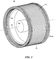
- a wind turbine 10 includes a turbine rotor 20 having blades 22 connected to a hub 24.
- the wind turbine 10 also includes an electrical generator 30 which is driven by a drive shaft 90 that extends between the generator 30 and the hub 24.
- the generator 30 is housed in a nacelle 26, shown partially cut away with the turbine rotor 20 protruding through an opening in an end of the nacelle 26.
- the generator 30 is configured for use in low frequency applications, and rotates at the same frequency as the turbine rotor 20.
- the generator 30 is configured to operate at around 11 rpm and generate 10 Megawatts of power or more.
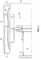
- the generator 30 is a direct-drive, synchronous, rotating superconducting machine that includes a rotor assembly 60 containing an HTS field winding and a stator assembly 40 containing a non-superconducting stator winding, for example, a copper stator winding.
- the rotor assembly 60 is supported within the stator assembly 40 so that the rotor and stator assemblies are coaxial about a drive shaft 90 and a longitudinal axis 15 of the generator 30.
- the stator assembly 40 includes a stator core 42 and stator windings 46 supported within the stator core 42.
- the stator core 42 is a hollow cylindrical body formed as an assembly of laminated arc sections that form annular ferromagnetic plates 44.
- the stator windings 46 are formed of transposed wire cables (not shown), in which the individual copper wire conductors (not shown) are twisted and/or woven to form a pattern which reduces conduction losses.
- the transposed cables may include Litz wire, Rutherford wire, Robel wire, or any other suitable transposed or series-wound wire.
- the transposed cables are wound around an axis transverse to the longitudinal axis 15 of the generator 30 to form an elongated multi-turn stator winding 46 having a conventional shape such as diamond or cranked, and the stator windings 46 are cooled by conventional means.
- the rotor assembly 60 includes a rotor winding assembly 62 and a torque transfer assembly 80 which are surrounded by an electromagnetic shield 50.
- the electromagnetic shield 50 includes a conductive, non-magnetic material that shields rotor windings 64 within the rotor winding assembly 62 by attenuating asynchronous fields produced by the stator currents.
- the electromagnetic shield 50 shields the rotor winding assembly 62 from heat generated in the stator assembly 40.
- the rotor winding assembly 62 includes multiple rotor windings 64, each formed of a high-temperature superconductor (HTS) conductor 102 wound around a mandrel 66.
- HTS high-temperature superconductor
- the rotor windings 64 of this embodiment are in the form of a saddle coil, as discussed further below.
- the rotor windings 64 and mandrel 66 are disposed on a cylindrical rotor winding support tube 68, and the rotor windings 64, mandrel 66 and rotor winding support tube 68 are all enclosed within a cryostat 70.
- the rotor windings 64 are conduction cooled through the rotor support tube 68.
- a cryogenic cooling system as described in co-pending US application 12/045,973 , the contents of which are incorporated by reference herein, is used to cool the rotor support tube 68.
- cryocoolers are distributed about the circumference of the support tube 68.
- Each cryocooler includes a cold head connected to the rotor support tube 68, and a circulator (not shown) that circulates a coolant to and from the thermal load connected to the cryocooler, whereby the cryocooler and circulator are configured to rotate along with the rotor support tube 68.
- the torque transfer assembly 80 is disposed radially inward relative to the rotor winding assembly 62, and rotatably and coaxially supports the rotor assembly 60 within the stator assembly 40. In addition, the torque transfer assembly 80 supports the rotor winding assembly 62 and transfers the rotational forces generated by the rotor winding assembly 62 to a drive shaft 90.
- the torque transfer assembly 80 includes a rotor body 82 which supports and positions the support tube 68 relative to the stator assembly 40, the drive shaft 90, and a torque limiting coupling 100 which connects the rotor body 82 to the drive shaft 90.
- One end 94 of the drive shaft 90 is connected to the rotor body 82 via the torque limiting coupling 100.
- the opposed end 92 of the drive shaft 90 is supported by the nacelle 26 through support bearings 28 (best seen in Fig. 2 ).
- the rotor body 82, torque limiting coupling 100 and drive shaft 90 reside outside the cold space defined by the cryostat 70, and thus operate at ambient temperature.
- the saddle-type rotor winding 64 is formed of a single electrical conductor 102.
- the electrical conductor 102 is a high temperature superconducting (HTS) tape having a generally rectangular cross sectional shape, and a length that is much greater in dimension than its width or thickness.
- the conductor 102 includes an A-axis that extends in a direction corresponding to a conductor length in the direction of current transmission.
- the conductor 102 also includes a B-axis transverse to the A-axis, the B-axis extending in a direction corresponding to the conductor width w c , and a C-axis transverse to both the A-axis and the B-axis, the C-axis extending in a direction corresponding to the conductor thickness t c .
- this reference frame is set with reference to the geometry of the conductor 102 as a whole, and is separate from the crystallographic coordinates of the superconducting material provided within the conductor 102.
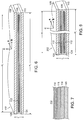
- the conductor 102 is a laminated assembly including a first support lamina 108, a second support lamina 110, at least one HTS insert 112 disposed between the first and second support lamina 108, 110 in a layered arrangement, and a solder filler 124 that encloses the HTS insert 112, connects the HTS insert 112 to each of the first and second support lamina 108, 110, and forms a fillet 126, as discussed further below.
- the conductor 102 is encased within an insulative epoxy coating (not shown).
- the laminated conductor assembly shown in Fig. 6 which includes a single HTS insert 112, is referred to as a "three-ply" conductor.
- the first and second support lamina 108, 110 are formed of an electrically conductive material such as metal, and are used to strengthen the conductor 102.
- the first and second support lamina 108, 110 may be formed of copper, copper alloy, stainless steel, brass, or composites thereof.
- the first support lamina 108 is formed of the same material as the second support lamina 110.
- the filler material 124 completely surrounds the insert 112. Although the filler material 124 generally fills the available space between the first support lamina 108 and the second support lamina 110, a fillet 126 is formed along the lateral edges of the filler material 124, where a shallow meniscus forms due to surface tension during manufacturing.
- the filler material 124 mechanically bonds all components together.
- solders can be used as the filler material 124, and the specific solder used is selected based on the requirements (thermal, electrical and mechanical) of the particular application.
- the filler material 124 may be selected from Pb-Sn solders, Sn solders, or other solders.
- the HTS insert 112 is also a laminate structure, and includes a metal substrate 120.
- the metal substrate 120 is formed of a ferromagnetic material.
- the metal substrate 120 may be formed of NiW.
- At least a surface of the metal substrate 120 is biaxially textured to provide a crystal template for one or more buffer layers 118 and the HTS layer 116.
- the buffer layers 118 overlie the metal substrate 120.
- the buffer layers 118 are made up of an electrically insulating material, though electrically conductive materials can be used.
- the buffer layers 118 are made up of, e.g., an inert metal, an oxide, zirconate, titanate, niobate, nitride, tantalate, aluminate, cuprate, manganate, or ruthenate of a metal or rare earth element (e.g. Al 2 O 3 , CeO 2 , Y 2 O 3 , MgO, Gd 2 O 3 , strontium titanate, gadolinium zirconate, yttria-stabilized zirconia, AlN, Si 3 N 4 , LaMnO 4 , La 2 Zr 2 O 7 , or La 2-x Ce x Zr 2 O 7 ).
- a metal or rare earth element e.g. Al 2 O 3 , CeO 2 , Y 2 O 3 , MgO, Gd 2 O 3 , strontium titanate, gadolinium zirconate, yttria-stabilized zirconia, AlN, Si 3 N
- the HTS layer 116 overlies the buffer layers 118 and may be any HTS material.
- the HTS layer includes a rare earth-alkaline earth-copper oxide, such as YBCO.
- a cap layer 114 overlies the HTS layer 116 and protects the HTS layer from chemical and mechanical degradation.
- the cap layer 114 may be sputtered Ag or other inert metal.
- the HTS insert 112 is fabricated using a wide-strip manufacturing process that permits multiple wires to be produced in desired widths from a single 4 - 10 cm wide web. Thus, relatively wide conductors can be formed, permitting higher currents in a single wire.
- the conductor 102 is wound around the mandrel 66 about a T-axis that is transverse to the longitudinal axis 15 of the generator 30. Since the mandrel 66 is generally in the form of an elongated oval, the rotor winding 64 includes straight portions 64a along the long sides of the mandrel 66, and curved portions 64b along the relatively shorter, rounded ends of the mandrel 66.
- the conductor 102 is wound about the mandrel 66 so that within the straight portions 64a, the conductor B-axis is parallel to a radius R of the rotor assembly 60, and is normal to the outer surface of the support tube 68. It is understood that the radius R and the T-axis are coaxial in the center of the mandrel 66, and that the radius R has a slight angular deviation relative to the T-axis at locations adjacent a periphery of the mandrel 66.
- the conductor 102 is wound at least 300-400 turns about the T-axis.
- the coil winding 64 is seen in cross-section as shown in Fig. 6 , multiple layers of the conductor 102 are arranged along the C-axis of the conductor.
- the cross-sections of conductor 102 are not drawn to scale in Figure 8 to permit visualization of the orientation of the conductor layers within the rotor winding 64.
- the conductor 102 is arranged in a single layer such that the dimension of the rotor winding 64 along the radius R is the same as the B-axis dimension of the conductor 102 (e.g., the conductor width w c ).
- the coil winding 64 is possible to form in a single layer due to its relatively large width (w c ).
- the single-layer saddle winding configuration is advantageous since it is relatively simple, more mechanically robust as compared to other configurations such as a multiple pancake stack forming an arc section, and permits very efficient packing of the conductor in the available space.
- a saddle winding on a large diameter is very nearly the same as a pancake winding.
- one advantage of the saddle winding is that it conforms to the surface of a tube.
- a C-axis strength of greater than 21 MPa is critical in order to prevent delamination of the conductor, for example due to the layered arrangement of the conductor 102 along the C-axis direction to form the turns of a coil winding, and the unequal thermal contraction properties of the epoxy that surrounds the conductor 102 and the metals which form the conductor 102.
- the required C-axis strength is achieved by forming the conductor 102 such that the width dimension of the filler material 124 on each side of the insert 112 is at least 10 percent of a width of the conductor 102, as measured in the width direction (e.g., along the B-axis) at a location between the first support lamina 108 and second support lamina 110 corresponding to the location of the insert 112. In the three-ply conductor 102, this location generally corresponds to the mid-thickness (e.g., midpoint in the C-axis direction) of the conductor 102.
- the insert 112 including the HTS layer 116 is formed having an insert width w; that is less than the conductor width w c .
- area within the conductor 102 that would conventionally be filled by superconductive material is instead filled with filler material 124, whereby current is traded in order to achieve the C-axis strength characteristics required in a rotor winding 64.
- the conductor 102 is formed having a conductor width w c , corresponding to a width of the support lamina 108, 110, of 12.0 mm, and a thickness of 0.050 mm.
- the insert 112 is provided in a width w; of 9.0 mm.
- the insert width w i is chosen to that the smallest fillet width on each side of the insert 112 is greater than 10 percent of the conductor width w c .
- the percentage of the conductor width of the total fillet width corresponds to ((w c - w i ) / w c .)* 100.
- the percentage of the conductor width of the fillet width on each side of the insert 112 corresponds to ((w c - w i ) / 2w c .)*100, and is required to be at least 10 percent.
- these percentages neglect the concavity of the fillet 126, they are acceptable since the overall thickness of the conductor 102 is small, whereby the concavity is very slight.
- the width dimension of the filler material 124 on each side of the insert 112 is 12.5 percent.
- the conductor dimensions are not limited to the 12-9 configuration described above.
- the conductor 102 can be formed having increased insert width.
- the conductor 102 may be formed having a conductor width w c , of 16.0 mm.
- the corresponding insert 112 is provided in a width w i of 11.8 mm.
- the width dimension of the filler material 124 on each side of the insert 112 is 13 percent.
- an alternative embodiment conductor 202 is identical to the three-ply conductor 102 except that it includes two HTS inserts 112, 112', and is referred to as a "four-ply" conductor.
- a conductor 202 having two inserts 112, 112' higher current carrying capacity is obtained relative to the conductor 102, which has a single insert 112.
- the HTS inserts 112, 112' are structurally identical, and are arranged between the lamina in such a way that the ordering of the layers of a first of the HTS inserts 112 mirrors the ordering of the layers of the second of the HTS inserts 112' as seen across an axis through the mid-thickness of the conductor and parallel to the B-axis.
- the HTS inserts 112, 112' are arranged so that the ordering of the layers is generally cap layer 114/HTS layer 116/buffer layer(s) 118/metal substrate 120/metal substrate 120'/buffer layer(s) 118'/HTS layer 116'/cap 114'.
- the HTS inserts 112, 112' are arranged so that the HTS layers 116, 116' are located outward relative to the respective metal substrates 120, 120'.
- the respective HTS layers 116, 116' electrically shield the metal substrate layers 120, 120', a configuration that lowers AC losses relative to a HTS tape configuration in which the ordering of inserts 112 is repeated, rather than mirrored, across the axis.
- a conductor configuration that includes a wide fillet width addresses the coil winding failure mode in which a high C-axis stress that tends to delaminate the conductor is applied to the laminate due to cooling of the epoxy.
- delamination can be avoided by forming a conductor in which the C-axis tensile strength of the conductor is higher than the strain relief point of the epoxy.
- the minimum conductor C-axis strength is 21 MPa.
- the required C-axis strength is achieved by forming the conductor 202 such that the width dimension of the filler material 124 on each side of the HTS inserts 112, 112' is at least 10 percent of a width of the conductor 202, as measured in the width direction (e.g., along the B-axis) at a location between the first support lamina 108 and second support lamina 110 corresponding to the locations of the HTS inserts 112, 112'. In the four-ply conductor 102, this location generally corresponds to the mid-thickness (e.g., midpoint in the C-axis direction) of the conductor 202.
- Figure 10 is a graph of measured C-axis failure stress for samples of the following three different configurations of a four-ply conductor: A first example conductor having a conductor width w c , of 16.0 mm and an insert width w i of 11.8 mm; a second example conductor having a conductor width w c , of 12.0 mm and an insert width w i of 9.0 mm; and a third example conductor having a conductor width w c , of 12 mm and an insert width w; of 10 mm.
- the first and second example conductors have fillet widths on each side of the insert that are 13.1 percent and 12.5 percent of the conductor width, respectively.
- the third example conductor results in a fillet width on each side of the insert that is only 8.3 percent of the conductor width. This graph illustrates that that increasing fillet width generally results in an increased C-axis tensile failure strength.
- the conductor edge is a crack nucleation site generated by a slitting process that occurs during manufacture of the conductor 102, 202.
- a wider fillet 126 provides more tensile strength right at the potential crack nucleation site.
- Each of the examples shown in Fig. 10 demonstrates a C-axis tensile strength that is in excess of 21 MPa. However, as discussed below, the third example conductor does not reliably demonstrate a C-axis tensile strength that is at least 21 MPa. Thus, the third example conductor of Fig. 10 , having a fillet width that is less than 10 percent, would not be suitable for use in the rotor winding 64.
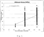
- Fig. 11 which illustrates the relationship between fillet width (expressed as a percentage of conductor width) and ultimate tensile stress as measured in the C-axis direction, it can be seen that higher ultimate tensile stress is obtained for conductors in which the percent fillet width to total conductor width is greater.
- this figure illustrates that those conductors 102, 202 having fillet widths on each side of the insert 112 that are greater than 10 percent of the conductor width have a mechanical strength that is reliably greater than 21 MPa.
- a conductor 102, 202 is considered to be reliable when 99.7 percent of the C-axis tensile test data lies within three standard deviations of the test data mean.
- the difference between the mean conductor C-axis tensile strength and three standard deviations of the mean conductor C-axis tensile strength must be 21 MPa for the conductor 102, 202.
- Conductors which meet this standard have a very high probability of being reliable, and reliability is a critical feature of a coil winding since it very difficult and costly to replace a defective coil winding 64 once assembled within generator 30.
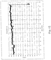
- Figure 12 is a graph of critical current Ic measured at intervals along 240 meters of a four-ply conductor 202 having a lamina width of 16 mm and insert width of 11.8.
- the conductor 202 demonstrates a high current carrying capacity (for example, a critical current Ic of about 600 Amperes), whereby a single-conductor winding 64 formed of the conductor 202 would also provide similar high current carrying capacity. As such, generator windings having multiple coils in parallel can be avoided.
- the critical current Ic has little variation along the length of the conductor.
- the coil winding 64 e.g. the ability to carry 600 Amperes per turn or more
- the coil winding is formed of a four-ply HTS conductor 202, and the conductor 202 is formed having a large width w c , for example 12 mm, 16 mm or more, as discussed further below.
- the large conductor width w c permits a single-layer arrangement of conductors 202 to be used within the arc section (see Fig.
- An HTS machine employing the single-layer winding 64 including the four-ply conductor 202 will have a smaller size and weight relative to some conventional machines, and still provide an operating current of 600 Amperes. This can be achieved, for example, when the air gap flux density is greater than 1.5 T, the effective air gap between rotor iron and stator back iron is approximately 200 mm, and the arc section of has a single layer winding turns count greater than 400 turns for an insulated turn thickness of 400 microns.
- the conductors 102, 202 are described herein as including two support lamina 108, 110, the conductors may be formed having more than two lamina.
- the first support lamina 108 is not necessarily formed of the same material as the second support lamina 110.
- the conductors 102, 202 may include lamina formed of dissimilar materials.
- the support lamina 108, 110 are described as having a thickness of 0.050 mm, the support lamina may be formed having thicknesses other than 0.050 mm.
- the conductors 102, 202 are described herein as having one or two inserts, the conductors are not limited to this number of inserts. In some embodiments, the conductors may be formed having more than two inserts. Moreover, normal metal may be disposed between respective inserts.
- the rotor windings 64 are conduction cooled through the rotor support tube 68 using a cryogenic cooling system, but conduction cooling of the rotor windings can be achieved using other techniques.
- cooling tubes are welded to the outer surface of the rotor support tube 68 intermediate the rotor windings 64.
- the cooling tubes may be disposed on the mandrel 66 and/or windings 64 themselves.
- other methods for cooling the rotor windings 4 may be substituted for the cooling tube arrangement.
- gaseous helium is circulated inside the cryostat 70 to cool the rotor windings 64.
- the coolant supply lines (not shown) that permit inward and outward flow of the gaseous helium to the rotor winding assembly 62 pass through a coaxial helium transfer coupling (not shown), which is a stationary-to-rotating union.
Landscapes
- Engineering & Computer Science (AREA)
- Power Engineering (AREA)
- General Engineering & Computer Science (AREA)
- Chemical & Material Sciences (AREA)
- Ceramic Engineering (AREA)
- Mechanical Engineering (AREA)
- Superconductive Dynamoelectric Machines (AREA)
- Windings For Motors And Generators (AREA)
Applications Claiming Priority (2)
| Application Number | Priority Date | Filing Date | Title |
|---|---|---|---|
| US13/435,156 US8791052B2 (en) | 2012-03-30 | 2012-03-30 | Wide electrical conductor having high C-axis strength |
| PCT/US2013/034059 WO2013148811A2 (en) | 2012-03-30 | 2013-03-27 | Wide electrical conductor having high c-axis strength |
Publications (2)
| Publication Number | Publication Date |
|---|---|
| EP2831987A2 EP2831987A2 (en) | 2015-02-04 |
| EP2831987B1 true EP2831987B1 (en) | 2018-01-31 |
Family
ID=48050338
Family Applications (1)
| Application Number | Title | Priority Date | Filing Date |
|---|---|---|---|
| EP13714832.6A Active EP2831987B1 (en) | 2012-03-30 | 2013-03-27 | Wide electrical conductor having high c-axis strength |
Country Status (6)
| Country | Link |
|---|---|
| US (1) | US8791052B2 (es) |
| EP (1) | EP2831987B1 (es) |
| JP (1) | JP6197026B2 (es) |
| KR (1) | KR101641013B1 (es) |
| ES (1) | ES2661036T3 (es) |
| WO (1) | WO2013148811A2 (es) |
Families Citing this family (5)
| Publication number | Priority date | Publication date | Assignee | Title |
|---|---|---|---|---|
| DK178999B1 (en) * | 2015-12-03 | 2017-07-31 | Envision Energy Denmark Aps | Synchronous superconductive rotary machine having a consecutive pole arrangement |
| US10804010B2 (en) | 2017-05-12 | 2020-10-13 | American Superconductor Corporation | High temperature superconducting wires having increased engineering current densities |
| US10601299B2 (en) * | 2017-09-07 | 2020-03-24 | American Superconductor Corporation | High temperature superconductor generator with increased rotational inertia |
| US10669001B2 (en) | 2017-12-11 | 2020-06-02 | American Superconductor Corporation | Hybrid electrical and mechanical propulsion and energy system for a ship |
| GB201814357D0 (en) * | 2018-09-04 | 2018-10-17 | Tokamak Energy Ltd | Alignment of HTS tapes |
Citations (1)
| Publication number | Priority date | Publication date | Assignee | Title |
|---|---|---|---|---|
| US6784362B1 (en) * | 1999-07-23 | 2004-08-31 | American Superconductor Corporation | Polymer encapsulated ceramic superconductors |
Family Cites Families (12)
| Publication number | Priority date | Publication date | Assignee | Title |
|---|---|---|---|---|
| EP0092228B1 (en) | 1982-04-19 | 1988-01-20 | Nissan Motor Co., Ltd. | Method and apparatus for controlling reduction ratio of continuously variable transmission |
| US5777420A (en) | 1996-07-16 | 1998-07-07 | American Superconductor Corporation | Superconducting synchronous motor construction |
| AU2001260972A1 (en) | 2000-01-20 | 2001-08-07 | American Superconductor Corporation | Pre-treatments for the encapsulation of superconducting composites |
| DE10303307B4 (de) * | 2003-01-28 | 2010-12-30 | Siemens Ag | Maschine mit einem Rotor und einer supraleltenden Rotorwicklung |
| US6759781B1 (en) | 2003-02-14 | 2004-07-06 | American Superconductor Corporation | Rotor assembly |
| US7816303B2 (en) * | 2004-10-01 | 2010-10-19 | American Superconductor Corporation | Architecture for high temperature superconductor wire |
| CA2658009C (en) * | 2006-07-21 | 2013-05-14 | American Superconductor Corporation | High-current, compact flexible conductors containing high temperature superconducting tapes |
| JP4864785B2 (ja) | 2007-03-27 | 2012-02-01 | 株式会社東芝 | 高温超電導線材、高温超電導コイルおよびその製造方法 |
| DE112008000039T5 (de) * | 2007-08-14 | 2010-03-04 | Sumitomo Electric Industries, Ltd. | Supraleitendes Band und Verfahren zu dessen Herstellung |
| JP5525876B2 (ja) * | 2010-03-17 | 2014-06-18 | 株式会社東芝 | 絶縁被覆酸化物超電導線材および樹脂含浸超電導コイル |
| US8886266B2 (en) * | 2010-06-21 | 2014-11-11 | Sumitomo Electric Industries, Ltd. | Superconducting coil, rotating device, and superconducting coil manufacturing method |
| JP2014002833A (ja) * | 2010-09-24 | 2014-01-09 | Fujikura Ltd | 酸化物超電導線材およびその製造方法 |
-
2012
- 2012-03-30 US US13/435,156 patent/US8791052B2/en active Active
-
2013
- 2013-03-27 JP JP2015503518A patent/JP6197026B2/ja active Active
- 2013-03-27 KR KR1020147030402A patent/KR101641013B1/ko active IP Right Grant
- 2013-03-27 EP EP13714832.6A patent/EP2831987B1/en active Active
- 2013-03-27 WO PCT/US2013/034059 patent/WO2013148811A2/en active Application Filing
- 2013-03-27 ES ES13714832.6T patent/ES2661036T3/es active Active
Patent Citations (1)
| Publication number | Priority date | Publication date | Assignee | Title |
|---|---|---|---|---|
| US6784362B1 (en) * | 1999-07-23 | 2004-08-31 | American Superconductor Corporation | Polymer encapsulated ceramic superconductors |
Non-Patent Citations (1)
| Title |
|---|
| HASEGAWA T ET AL: "Fabrication and properties of Bi2Sr2CaCu2Oy multilayer superconducting tapes and coils", IEEE TRANSACTIONS ON APPLIED SUPERCONDUCTIVITY, IEEE SERVICE CENTER, LOS ALAMITOS, CA, US, vol. 7, no. 2, 1 June 1997 (1997-06-01), pages 1703 - 1706, XP011501413, ISSN: 1051-8223, DOI: 10.1109/77.620907 * |
Also Published As
| Publication number | Publication date |
|---|---|
| JP2015515847A (ja) | 2015-05-28 |
| US8791052B2 (en) | 2014-07-29 |
| WO2013148811A3 (en) | 2014-10-16 |
| WO2013148811A2 (en) | 2013-10-03 |
| KR20150003227A (ko) | 2015-01-08 |
| JP6197026B2 (ja) | 2017-09-13 |
| US20130261000A1 (en) | 2013-10-03 |
| ES2661036T3 (es) | 2018-03-27 |
| EP2831987A2 (en) | 2015-02-04 |
| KR101641013B1 (ko) | 2016-07-19 |
Similar Documents
| Publication | Publication Date | Title |
|---|---|---|
| JP3953813B2 (ja) | 超伝導磁気コイルを備えるロータアセンブリ | |
| EP1639609B1 (en) | Novel superconducting articles | |
| EP1877246B2 (en) | Joined superconductive articles | |
| US20080161189A1 (en) | Superconducting Electrical Machines | |
| Abrahamsen et al. | Large superconducting wind turbine generators | |
| EP2831987B1 (en) | Wide electrical conductor having high c-axis strength | |
| US8436499B2 (en) | Electrical machine with superconducting armature coils and other components | |
| EP2131407A1 (en) | Superconducting wire with low AC losses | |
| JP5154953B2 (ja) | 低密度特徴を持つ超伝導性物品 | |
| US6711421B2 (en) | Structural reinforced superconducting ceramic tape and method of making | |
| WO2021262319A2 (en) | Cabling method of superconducting flat wires | |
| US7417192B2 (en) | Superconductor components | |
| Iwakuma et al. | Production and test of a REBCO superconducting synchronous motor | |
| US8260387B2 (en) | Superconducting articles and methods of fabrication thereof with reduced AC magnetic field losses | |
| Oberly et al. | The importance of interfilamentary barrier resistance in YBCO coated conductor to minimize ac losses | |
| JP2015035308A (ja) | 酸化物超電導線材の接続構造体、及びこれを備えた超電導機器 | |
| US20210375541A1 (en) | Electrical machine and method for fabrication of a coil of an electrical machine | |
| Rodenbush et al. | Performance of high temperature superconducting coils for implementation into megawatt class generators | |
| Masur et al. | Industrial HTS conductors: Status and applications | |
| Mumford | High temperature superconductors: impact on machine design-present state of the art from an industrial manufacturer's point of view |
Legal Events
| Date | Code | Title | Description |
|---|---|---|---|
| PUAI | Public reference made under article 153(3) epc to a published international application that has entered the european phase |
Free format text: ORIGINAL CODE: 0009012 |
|
| 17P | Request for examination filed |
Effective date: 20141024 |
|
| AK | Designated contracting states |
Kind code of ref document: A2 Designated state(s): AL AT BE BG CH CY CZ DE DK EE ES FI FR GB GR HR HU IE IS IT LI LT LU LV MC MK MT NL NO PL PT RO RS SE SI SK SM TR |
|
| AX | Request for extension of the european patent |
Extension state: BA ME |
|
| DAX | Request for extension of the european patent (deleted) | ||
| 17Q | First examination report despatched |
Effective date: 20151009 |
|
| STAA | Information on the status of an ep patent application or granted ep patent |
Free format text: STATUS: EXAMINATION IS IN PROGRESS |
|
| GRAP | Despatch of communication of intention to grant a patent |
Free format text: ORIGINAL CODE: EPIDOSNIGR1 |
|
| STAA | Information on the status of an ep patent application or granted ep patent |
Free format text: STATUS: GRANT OF PATENT IS INTENDED |
|
| INTG | Intention to grant announced |
Effective date: 20170919 |
|
| GRAS | Grant fee paid |
Free format text: ORIGINAL CODE: EPIDOSNIGR3 |
|
| GRAA | (expected) grant |
Free format text: ORIGINAL CODE: 0009210 |
|
| STAA | Information on the status of an ep patent application or granted ep patent |
Free format text: STATUS: THE PATENT HAS BEEN GRANTED |
|
| AK | Designated contracting states |
Kind code of ref document: B1 Designated state(s): AL AT BE BG CH CY CZ DE DK EE ES FI FR GB GR HR HU IE IS IT LI LT LU LV MC MK MT NL NO PL PT RO RS SE SI SK SM TR |
|
| REG | Reference to a national code |
Ref country code: GB Ref legal event code: FG4D Ref country code: CH Ref legal event code: EP |
|
| REG | Reference to a national code |
Ref country code: AT Ref legal event code: REF Ref document number: 968206 Country of ref document: AT Kind code of ref document: T Effective date: 20180215 |
|
| REG | Reference to a national code |
Ref country code: IE Ref legal event code: FG4D |
|
| REG | Reference to a national code |
Ref country code: DE Ref legal event code: R096 Ref document number: 602013032571 Country of ref document: DE |
|
| REG | Reference to a national code |
Ref country code: FR Ref legal event code: PLFP Year of fee payment: 6 |
|
| REG | Reference to a national code |
Ref country code: ES Ref legal event code: FG2A Ref document number: 2661036 Country of ref document: ES Kind code of ref document: T3 Effective date: 20180327 |
|
| REG | Reference to a national code |
Ref country code: NL Ref legal event code: MP Effective date: 20180131 |
|
| REG | Reference to a national code |
Ref country code: LT Ref legal event code: MG4D |
|
| PG25 | Lapsed in a contracting state [announced via postgrant information from national office to epo] |
Ref country code: LT Free format text: LAPSE BECAUSE OF FAILURE TO SUBMIT A TRANSLATION OF THE DESCRIPTION OR TO PAY THE FEE WITHIN THE PRESCRIBED TIME-LIMIT Effective date: 20180131 Ref country code: HR Free format text: LAPSE BECAUSE OF FAILURE TO SUBMIT A TRANSLATION OF THE DESCRIPTION OR TO PAY THE FEE WITHIN THE PRESCRIBED TIME-LIMIT Effective date: 20180131 Ref country code: NL Free format text: LAPSE BECAUSE OF FAILURE TO SUBMIT A TRANSLATION OF THE DESCRIPTION OR TO PAY THE FEE WITHIN THE PRESCRIBED TIME-LIMIT Effective date: 20180131 Ref country code: NO Free format text: LAPSE BECAUSE OF FAILURE TO SUBMIT A TRANSLATION OF THE DESCRIPTION OR TO PAY THE FEE WITHIN THE PRESCRIBED TIME-LIMIT Effective date: 20180430 Ref country code: FI Free format text: LAPSE BECAUSE OF FAILURE TO SUBMIT A TRANSLATION OF THE DESCRIPTION OR TO PAY THE FEE WITHIN THE PRESCRIBED TIME-LIMIT Effective date: 20180131 |
|
| PG25 | Lapsed in a contracting state [announced via postgrant information from national office to epo] |
Ref country code: RS Free format text: LAPSE BECAUSE OF FAILURE TO SUBMIT A TRANSLATION OF THE DESCRIPTION OR TO PAY THE FEE WITHIN THE PRESCRIBED TIME-LIMIT Effective date: 20180131 Ref country code: PL Free format text: LAPSE BECAUSE OF FAILURE TO SUBMIT A TRANSLATION OF THE DESCRIPTION OR TO PAY THE FEE WITHIN THE PRESCRIBED TIME-LIMIT Effective date: 20180131 Ref country code: GR Free format text: LAPSE BECAUSE OF FAILURE TO SUBMIT A TRANSLATION OF THE DESCRIPTION OR TO PAY THE FEE WITHIN THE PRESCRIBED TIME-LIMIT Effective date: 20180501 Ref country code: BG Free format text: LAPSE BECAUSE OF FAILURE TO SUBMIT A TRANSLATION OF THE DESCRIPTION OR TO PAY THE FEE WITHIN THE PRESCRIBED TIME-LIMIT Effective date: 20180430 Ref country code: IS Free format text: LAPSE BECAUSE OF FAILURE TO SUBMIT A TRANSLATION OF THE DESCRIPTION OR TO PAY THE FEE WITHIN THE PRESCRIBED TIME-LIMIT Effective date: 20180531 Ref country code: LV Free format text: LAPSE BECAUSE OF FAILURE TO SUBMIT A TRANSLATION OF THE DESCRIPTION OR TO PAY THE FEE WITHIN THE PRESCRIBED TIME-LIMIT Effective date: 20180131 Ref country code: SE Free format text: LAPSE BECAUSE OF FAILURE TO SUBMIT A TRANSLATION OF THE DESCRIPTION OR TO PAY THE FEE WITHIN THE PRESCRIBED TIME-LIMIT Effective date: 20180131 |
|
| PG25 | Lapsed in a contracting state [announced via postgrant information from national office to epo] |
Ref country code: AL Free format text: LAPSE BECAUSE OF FAILURE TO SUBMIT A TRANSLATION OF THE DESCRIPTION OR TO PAY THE FEE WITHIN THE PRESCRIBED TIME-LIMIT Effective date: 20180131 Ref country code: RO Free format text: LAPSE BECAUSE OF FAILURE TO SUBMIT A TRANSLATION OF THE DESCRIPTION OR TO PAY THE FEE WITHIN THE PRESCRIBED TIME-LIMIT Effective date: 20180131 Ref country code: IT Free format text: LAPSE BECAUSE OF FAILURE TO SUBMIT A TRANSLATION OF THE DESCRIPTION OR TO PAY THE FEE WITHIN THE PRESCRIBED TIME-LIMIT Effective date: 20180131 Ref country code: EE Free format text: LAPSE BECAUSE OF FAILURE TO SUBMIT A TRANSLATION OF THE DESCRIPTION OR TO PAY THE FEE WITHIN THE PRESCRIBED TIME-LIMIT Effective date: 20180131 |
|
| REG | Reference to a national code |
Ref country code: CH Ref legal event code: PL |
|
| REG | Reference to a national code |
Ref country code: DE Ref legal event code: R097 Ref document number: 602013032571 Country of ref document: DE |
|
| PG25 | Lapsed in a contracting state [announced via postgrant information from national office to epo] |
Ref country code: SK Free format text: LAPSE BECAUSE OF FAILURE TO SUBMIT A TRANSLATION OF THE DESCRIPTION OR TO PAY THE FEE WITHIN THE PRESCRIBED TIME-LIMIT Effective date: 20180131 Ref country code: CZ Free format text: LAPSE BECAUSE OF FAILURE TO SUBMIT A TRANSLATION OF THE DESCRIPTION OR TO PAY THE FEE WITHIN THE PRESCRIBED TIME-LIMIT Effective date: 20180131 Ref country code: SM Free format text: LAPSE BECAUSE OF FAILURE TO SUBMIT A TRANSLATION OF THE DESCRIPTION OR TO PAY THE FEE WITHIN THE PRESCRIBED TIME-LIMIT Effective date: 20180131 Ref country code: DK Free format text: LAPSE BECAUSE OF FAILURE TO SUBMIT A TRANSLATION OF THE DESCRIPTION OR TO PAY THE FEE WITHIN THE PRESCRIBED TIME-LIMIT Effective date: 20180131 Ref country code: MC Free format text: LAPSE BECAUSE OF FAILURE TO SUBMIT A TRANSLATION OF THE DESCRIPTION OR TO PAY THE FEE WITHIN THE PRESCRIBED TIME-LIMIT Effective date: 20180131 |
|
| PLBE | No opposition filed within time limit |
Free format text: ORIGINAL CODE: 0009261 |
|
| STAA | Information on the status of an ep patent application or granted ep patent |
Free format text: STATUS: NO OPPOSITION FILED WITHIN TIME LIMIT |
|
| REG | Reference to a national code |
Ref country code: BE Ref legal event code: MM Effective date: 20180331 |
|
| REG | Reference to a national code |
Ref country code: IE Ref legal event code: MM4A |
|
| PG25 | Lapsed in a contracting state [announced via postgrant information from national office to epo] |
Ref country code: LU Free format text: LAPSE BECAUSE OF NON-PAYMENT OF DUE FEES Effective date: 20180327 |
|
| 26N | No opposition filed |
Effective date: 20181102 |
|
| PG25 | Lapsed in a contracting state [announced via postgrant information from national office to epo] |
Ref country code: IE Free format text: LAPSE BECAUSE OF NON-PAYMENT OF DUE FEES Effective date: 20180327 |
|
| PG25 | Lapsed in a contracting state [announced via postgrant information from national office to epo] |
Ref country code: SI Free format text: LAPSE BECAUSE OF FAILURE TO SUBMIT A TRANSLATION OF THE DESCRIPTION OR TO PAY THE FEE WITHIN THE PRESCRIBED TIME-LIMIT Effective date: 20180131 Ref country code: LI Free format text: LAPSE BECAUSE OF NON-PAYMENT OF DUE FEES Effective date: 20180331 Ref country code: CH Free format text: LAPSE BECAUSE OF NON-PAYMENT OF DUE FEES Effective date: 20180331 Ref country code: BE Free format text: LAPSE BECAUSE OF NON-PAYMENT OF DUE FEES Effective date: 20180331 |
|
| PG25 | Lapsed in a contracting state [announced via postgrant information from national office to epo] |
Ref country code: MT Free format text: LAPSE BECAUSE OF NON-PAYMENT OF DUE FEES Effective date: 20180327 |
|
| PG25 | Lapsed in a contracting state [announced via postgrant information from national office to epo] |
Ref country code: TR Free format text: LAPSE BECAUSE OF FAILURE TO SUBMIT A TRANSLATION OF THE DESCRIPTION OR TO PAY THE FEE WITHIN THE PRESCRIBED TIME-LIMIT Effective date: 20180131 |
|
| PG25 | Lapsed in a contracting state [announced via postgrant information from national office to epo] |
Ref country code: PT Free format text: LAPSE BECAUSE OF FAILURE TO SUBMIT A TRANSLATION OF THE DESCRIPTION OR TO PAY THE FEE WITHIN THE PRESCRIBED TIME-LIMIT Effective date: 20180131 |
|
| PG25 | Lapsed in a contracting state [announced via postgrant information from national office to epo] |
Ref country code: MK Free format text: LAPSE BECAUSE OF NON-PAYMENT OF DUE FEES Effective date: 20180131 Ref country code: CY Free format text: LAPSE BECAUSE OF FAILURE TO SUBMIT A TRANSLATION OF THE DESCRIPTION OR TO PAY THE FEE WITHIN THE PRESCRIBED TIME-LIMIT Effective date: 20180131 Ref country code: HU Free format text: LAPSE BECAUSE OF FAILURE TO SUBMIT A TRANSLATION OF THE DESCRIPTION OR TO PAY THE FEE WITHIN THE PRESCRIBED TIME-LIMIT; INVALID AB INITIO Effective date: 20130327 |
|
| REG | Reference to a national code |
Ref country code: AT Ref legal event code: UEP Ref document number: 968206 Country of ref document: AT Kind code of ref document: T Effective date: 20180131 |
|
| PGFP | Annual fee paid to national office [announced via postgrant information from national office to epo] |
Ref country code: FR Payment date: 20230327 Year of fee payment: 11 |
|
| PGFP | Annual fee paid to national office [announced via postgrant information from national office to epo] |
Ref country code: ES Payment date: 20230403 Year of fee payment: 11 |
|
| P01 | Opt-out of the competence of the unified patent court (upc) registered |
Effective date: 20230810 |
|
| PGFP | Annual fee paid to national office [announced via postgrant information from national office to epo] |
Ref country code: AT Payment date: 20240304 Year of fee payment: 12 |
|
| PGFP | Annual fee paid to national office [announced via postgrant information from national office to epo] |
Ref country code: DE Payment date: 20240327 Year of fee payment: 12 Ref country code: GB Payment date: 20240327 Year of fee payment: 12 |