EP2831897B1 - Verbessertes kontaktsystem mit doppelunterbrechung für gekapselte leistungsschalter - Google Patents
Verbessertes kontaktsystem mit doppelunterbrechung für gekapselte leistungsschalter Download PDFInfo
- Publication number
- EP2831897B1 EP2831897B1 EP12778426.2A EP12778426A EP2831897B1 EP 2831897 B1 EP2831897 B1 EP 2831897B1 EP 12778426 A EP12778426 A EP 12778426A EP 2831897 B1 EP2831897 B1 EP 2831897B1
- Authority
- EP
- European Patent Office
- Prior art keywords
- shaft
- contact
- spring
- contact system
- holder
- Prior art date
- Legal status (The legal status is an assumption and is not a legal conclusion. Google has not performed a legal analysis and makes no representation as to the accuracy of the status listed.)
- Active
Links
- 230000006835 compression Effects 0.000 claims description 9
- 238000007906 compression Methods 0.000 claims description 9
- 230000033001 locomotion Effects 0.000 claims description 4
- RNFJDJUURJAICM-UHFFFAOYSA-N 2,2,4,4,6,6-hexaphenoxy-1,3,5-triaza-2$l^{5},4$l^{5},6$l^{5}-triphosphacyclohexa-1,3,5-triene Chemical compound N=1P(OC=2C=CC=CC=2)(OC=2C=CC=CC=2)=NP(OC=2C=CC=CC=2)(OC=2C=CC=CC=2)=NP=1(OC=1C=CC=CC=1)OC1=CC=CC=C1 RNFJDJUURJAICM-UHFFFAOYSA-N 0.000 claims description 2
- 239000003063 flame retardant Substances 0.000 claims description 2
- 239000012815 thermoplastic material Substances 0.000 claims description 2
- 238000010276 construction Methods 0.000 description 14
- 230000003628 erosive effect Effects 0.000 description 8
- 238000009413 insulation Methods 0.000 description 4
- 230000007246 mechanism Effects 0.000 description 4
- 230000009471 action Effects 0.000 description 3
- 238000000034 method Methods 0.000 description 3
- 230000004888 barrier function Effects 0.000 description 2
- 230000005520 electrodynamics Effects 0.000 description 2
- 239000007789 gas Substances 0.000 description 2
- 238000012986 modification Methods 0.000 description 2
- 230000004048 modification Effects 0.000 description 2
- 101000581533 Homo sapiens Methylcrotonoyl-CoA carboxylase beta chain, mitochondrial Proteins 0.000 description 1
- 102100027320 Methylcrotonoyl-CoA carboxylase beta chain, mitochondrial Human genes 0.000 description 1
- 230000005540 biological transmission Effects 0.000 description 1
- 230000015556 catabolic process Effects 0.000 description 1
- 239000004020 conductor Substances 0.000 description 1
- 230000000694 effects Effects 0.000 description 1
- 238000010891 electric arc Methods 0.000 description 1
- 238000005516 engineering process Methods 0.000 description 1
- 238000003780 insertion Methods 0.000 description 1
- 230000037431 insertion Effects 0.000 description 1
- 239000000463 material Substances 0.000 description 1
- 238000010791 quenching Methods 0.000 description 1
- 230000000171 quenching effect Effects 0.000 description 1
- 230000001846 repelling effect Effects 0.000 description 1
Images


Classifications
-
- H—ELECTRICITY
- H01—ELECTRIC ELEMENTS
- H01H—ELECTRIC SWITCHES; RELAYS; SELECTORS; EMERGENCY PROTECTIVE DEVICES
- H01H1/00—Contacts
- H01H1/12—Contacts characterised by the manner in which co-operating contacts engage
- H01H1/14—Contacts characterised by the manner in which co-operating contacts engage by abutting
- H01H1/20—Bridging contacts
- H01H1/2041—Rotating bridge
- H01H1/205—Details concerning the elastic mounting of the rotating bridge in the rotor
-
- H—ELECTRICITY
- H01—ELECTRIC ELEMENTS
- H01H—ELECTRIC SWITCHES; RELAYS; SELECTORS; EMERGENCY PROTECTIVE DEVICES
- H01H1/00—Contacts
- H01H1/02—Contacts characterised by the material thereof
- H01H1/021—Composite material
- H01H1/025—Composite material having copper as the basic material
-
- H—ELECTRICITY
- H01—ELECTRIC ELEMENTS
- H01H—ELECTRIC SWITCHES; RELAYS; SELECTORS; EMERGENCY PROTECTIVE DEVICES
- H01H1/00—Contacts
- H01H1/12—Contacts characterised by the manner in which co-operating contacts engage
- H01H1/14—Contacts characterised by the manner in which co-operating contacts engage by abutting
- H01H1/20—Bridging contacts
- H01H1/2041—Rotating bridge
- H01H1/2058—Rotating bridge being assembled in a cassette, which can be placed as a complete unit into a circuit breaker
-
- H—ELECTRICITY
- H01—ELECTRIC ELEMENTS
- H01H—ELECTRIC SWITCHES; RELAYS; SELECTORS; EMERGENCY PROTECTIVE DEVICES
- H01H71/00—Details of the protective switches or relays covered by groups H01H73/00 - H01H83/00
- H01H71/02—Housings; Casings; Bases; Mountings
- H01H71/025—Constructional details of housings or casings not concerning the mounting or assembly of the different internal parts
-
- H—ELECTRICITY
- H01—ELECTRIC ELEMENTS
- H01H—ELECTRIC SWITCHES; RELAYS; SELECTORS; EMERGENCY PROTECTIVE DEVICES
- H01H77/00—Protective overload circuit-breaking switches operated by excess current and requiring separate action for resetting
- H01H77/02—Protective overload circuit-breaking switches operated by excess current and requiring separate action for resetting in which the excess current itself provides the energy for opening the contacts, and having a separate reset mechanism
- H01H77/10—Protective overload circuit-breaking switches operated by excess current and requiring separate action for resetting in which the excess current itself provides the energy for opening the contacts, and having a separate reset mechanism with electrodynamic opening
- H01H77/102—Protective overload circuit-breaking switches operated by excess current and requiring separate action for resetting in which the excess current itself provides the energy for opening the contacts, and having a separate reset mechanism with electrodynamic opening characterised by special mounting of contact arm, allowing blow-off movement
- H01H77/104—Protective overload circuit-breaking switches operated by excess current and requiring separate action for resetting in which the excess current itself provides the energy for opening the contacts, and having a separate reset mechanism with electrodynamic opening characterised by special mounting of contact arm, allowing blow-off movement with a stable blow-off position
Definitions
- the present invention generally relates to contact system for circuit breakers, mainly moulded case circuit breakers (MCCBs). More particularly, the invention is concerned about a contact system comprising a spring arrangement where the moving contact flips open during short circuit condition.
- MCCBs moulded case circuit breakers
- Circuit breakers are used for switching and protection of electrical equipments. It consists mainly of current sensing means, mechanism and contact system.
- the contact system consists of a set of fixed contacts and a moving contact. During any fault (short-circuit) in the line, the moving contact is opens up and clears the fault.
- a set of springs provide contact force to maintain the moving contact in ON condition. Different arrangements of springs are followed currently for maintaining contact pressure.
- the contact system is made in such a way that the moving contact repels open during any fault in line due to electromagnetic forces. During this movement the electromagnetic force has to fully act against the springs providing contact pressure.
- US5534832 discloses a switch having at least one power switching pole includes a contact bridge cooperating with fixed contacts and adapted to be maneuvered either by mobile parts of a solenoid or by a tripping mechanism.
- the contact bridge is rotatable and the mobile parts of the solenoid operate the contact bridge through the intermediary of a transmission mechanism. Referring figure 1a it would be found that the contact system is compression spring based non flappable type.
- US5310971 discloses a molded case low voltage circuit breaker comprising a rotary contact bridge, a pair of stationary contacts cooperating with the contact bridge, current input conductors to the stationary contacts arranged to generate electrodynamic forces repelling the contact bridge to a repelled open position when a short-circuit occurs, a rotary bar having a transverse orifice housing with clearance the contact bridge which protrudes out from both sides of the bar, at least one pair of tension springs fitted between the bar and the contact bridge to provide a contact pressure of the contact bridge on the stationary contacts in closed position of the circuit breaker, while allowing rotation of the contact bridge to the repelled open position due to the electrodynamic forces.
- the system of the prior art is extension spring based. Reference is drawn to figure 1b .
- US6870112 discloses a low-voltage circuit breaker that allows optimum execution of the electrical switching operations, allowing in particular to eliminate or at least minimize the possibility that in short-circuit conditions the moving contact bounces toward the fixed one, with consequent restriking of the electric arc, with a constructive structure that is simple and functionally effective and does not require additional latching elements during opening.
- the contact system described in this prior art document is extension spring and profile based as shown in figure 1c .
- US7394032 discloses an electrodynamically tilting contact system for power circuit breakers, especially for current-limiting circuit breakers, in which a breaker shaft segment, a rotary contact bridge pivotably mounted therein and contact force springs constitute components of a tilting snap-action mechanism that holds the rotary contact bridge in a repulsed position after the fixed contacts have been electrodynamically repulsed.
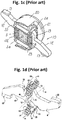
- the prior system is a compression spring based profile type contact system as shown in figure 1d .
- Fig 1a and 1d shows compression spring based shaft construction, where as Fig 1b and 1c shows extension spring based shaft construction.
- the arrangement shown in Fig 1a is a non flappable type of contact system. This causes the spring to continuously oppose the moving contact, thus reducing the efficiency of short circuit breaking.
- the arrangement shown in Fig 1b and 1c are profile based systems in which the springs apply contact pressure through cam action. This causes increased friction on the contacts, thus reducing the efficiency of short circuit breaking.
- the arrangement shown in Fig 1d is a compression spring based system. But the force is transferred to contact through cam action. This can lead to non stability of moving contact and can also increase friction.
- Fig.2 shows the variation of contact pressure with erosion for a conventional system. This decrease in contact pressure causes increased resistance between contacts. This causes problems of higher temperature rise in the breaker. This also increases the burden on other components in the breaker.
- the conventional technology for shaft construction uses an open shaft construction or partially closed construction.
- For rotation of moving contact with respect to the shaft there has to be an opening in the shaft with slot length depending on degree of rotation of moving contact. This produces the following problems:
- a spring arrangement can be uniquely designed in such a way that, for initial opening of contact system the spring force opposes the electromagnetic force and then after that aids the electromagnetic force. This arrangement helps in an increased opening velocity, which in turn helps in better breaking.
- the inventors have also found that in the newly designed double break contact system the contact pressure is maintained even after wear out of the contacts. This would help the breaker in maintaining the same level of performance even after erosion of contacts. Further the construction of the present invention has been provided with a movable shaft cover which rotates along with the moving contacts during repulsion when there is a short circuit.
- a basic object of the present invention is to overcome the disadvantages/drawbacks of the known art.
- Another object of the present invention is to provide an improved double break contact system for moulded case circuit breakers.
- Another object of the present invention is to provide a holder arrangement such that the system attains maximum stability.
- Another object is to provide minimal friction effect.
- an improved double break contact system for use in moulded case circuit breakers according to claim 1.
- Fig 3 shows the new MCCB contact system in ON condition.
- the current conduction happens through the fixed contact (1) onto the moving contact (3) and again to the second fixed contact (2).
- the compression spring (4) arranged between the holders (5) provide the contact force required to maintain the pressure between moving contacts (3) and fixed contacts (1 and 2) to desired levels.
- the contacts are designed (as in most of present MCCBs) in such a way that during short circuit conditions, an electromagnetic force acts between the moving contact and the fixed contacts. This force rotates the moving contact and brings it to repelled position as shown in Fig.4 .
- the fixed contact has been designed such that it helps in increasing the contact opening as compared to a conventional contact system. As shown separately in Fig.
- the fixed contacts (1 and 2) have a substantially U-shaped profile in which the contact portion which comes in contact with the moving contacts (3) comprises an inward bent portion (6).
- the holders (5) rotate on pins (7) mounted on the shaft (8).
- This arrangement provides easy rotation of holders and helps in channelizing the spring force exactly in the required direction.
- the moving contact is supported only by the holder arrangement. This enables moving contact to face minimal friction during movement.
- the arrangement of moving contact is shown in Fig.5 .
- This type of spring arrangement also enables the system to have a high contact opening than conventional systems.
- the shaft construction is also much simplified in this arrangement as compared to conventional systems.
- the arrangement of springs on the holder is shown in detail in Fig.14 .
- the holder arrangement as illustrated in Fig. 14 comprises two substantially rectangular sockets (9) having pins (10) located inside said sockets (9).
- the springs (4) are mounted on the said pins (10) and secured in the said sockets (9).
- the sockets (9) further comprise holes (11) at the top for pin mounting the holders on the shaft in a manner that holders are free to rotate on the shaft surface. It is to be noted in this context that the sockets have been described as rectangular in the present embodiment of the invention which should not be considered to be limiting scope of the invention.
- the shape of the sockets can be anything fulfilling the ergonomics of the other components/parts of the contact system.
- FIG.15 A different method of contact arrangement which is possible in this configuration is also shown in Fig.15 .
- This is a simpler arrangement as compared to the above mentioned concept, but needs more space for implementation.
- the contact systems are provided with limited space and therefore, the industry demands arrangements which can be functionally fitted in a specified space.
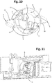
- Figure 8 shows enclosed shaft construction wherein the shaft cover (12) (also shown separately in Fig. 9 ) secures the shaft (8) and moving contact (3).
- the shaft cover (12) can be in the form of hollow cylinder with slots (13) for insertion of the moving contact (3).
- the shaft cover can be moulded out of flame retardant thermoplastic materials.
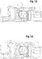
- the moving contact rotates with respect to the shaft. During this rotation, moving contact touches the shaft cover flaps (14) shown in Fig 9 , and thus rotates the shaft cover along with it.
- the shaft cover flaps (14) shown in Fig 9 When the moving contact opens fully during repulsion as show in Fig 12 , the shaft cover completely encloses the shaft. If shaft cover is not present as shown in Fig 13 , the shaft leaves an open slot after the moving contact has repelled.
Claims (6)
- Verbessertes Kontaktsystem mit Doppelunterbrechung zur Verwendung in gekapselten Leistungsschaltern, wobei das Kontaktsystem mit Doppelunterbrechung umfasst:ein Wellenmittel (8);feststehende Kontaktmittel (1, 2) und bewegliche Kontaktmittel (3), wobei die beweglichen Kontaktmittel (3) so an dem Wellenmittel (8) montiert sind, dass sich die beweglichen Kontaktmittel (3) bezüglich der Bewegung des Wellenmittels (8) drehen;Federmittel (4), die betriebsfähig an dem Wellenmittel (8) montiert sind;eine Halteranordnung (5, 7), umfassend Haltemittel (5) zum Sichern der Federmittel (4);wobei die Haltemittel (5) drehbar an dem Wellenmittel (8) auf eine solche Weise montiert sind, dass die Drehung des Wellenmittels (8) in Funktion die Haltemittel (5) dreht;wobei die Federmittel (4) dazu eingerichtet sind, eine Kraft bereitzustellen, die der elektromagnetischen Kraft entgegengesetzt ist, sowie eine Kraft, welche die elektromagnetische Kraft unterstützt; undwobei die feststehenden Kontaktmittel (1, 2) ein im Wesentlichen U-förmiges Profil mit einem Kontaktabschnitt aufweisen, der so ausgelegt ist, dass er mit den beweglichen Kontaktmitteln (3) in Kontakt kommen kann;dadurch gekennzeichnet, dassder Kontaktabschnitt des U-förmigen Profils der feststehenden Kontaktmittel (1, 2) einen nach innen gebogenen Abschnitt (6) umfasst,das Kontaktsystem des Weiteren Wellenabdeckungsmittel (12) zum Sichern des Wellenmittels (8) und der beweglichen Kontaktmittel (3) umfasst, wobei das Wellenabdeckungsmittel (12) die Form eines hohlen Zylinders mit einer umlaufenden Wand aufweist, wobei die umlaufende Wand Schlitzvorrichtungen (13) umfasst, durch welche die beweglichen Kontaktmittel (3) an die Außenseite des Wellenabdeckungsmittels (12) vorstehen, undwobei das Wellenabdeckungsmittel (12) des Weiteren eine Vielzahl von Wellenabdeckungsklappenmitteln (14) umfasst, die von der umlaufenden Wand nach außen vorstehen, so dass, wenn sich ein bewegliches Kontaktmittel (3) bezüglich des Wellenmittels (8) dreht, das bewegliche Kontaktmittel (3) ein entsprechendes Wellenabdeckungsklappenmittel (14) berührt und dadurch eine Drehung des Wellenabdeckungsmittels (12) bewirkt.
- Kontaktsystem nach Anspruch 1, wobei die Federmittel Druckfedern sind.
- Kontaktsystem nach Anspruch 2, wobei die Haltermittel (5) zwei Buchsenmittel (9) zum Aufnehmen von einer Druckfeder (4) dazwischen umfassen, wobei ein Stift (10) in jedem Buchsenmittel (9) angeordnet ist, an dem ein jeweiliges Ende der Druckfeder (4) montiert ist, um die Druckfeder (4) zwischen den Buchsenmitteln (9) zu sichern.
- Kontaktsystem nach Anspruch 1, wobei die Halteranordnung (5, 7) des Weiteren Stiftmittel (7) umfasst, die dazu eingerichtet sind, die Haltemittel (5) auf solche Weise an dem Wellenmittel (8) zu montieren, dass die Federmittel (4) mit der Drehung des Wellenmittels (8) drehbar sind, so dass die Federkraft exakt in der erwünschten Richtung kanalisiert werden kann.
- Kontaktsystem nach Anspruch 3 und 4, wobei jedes Buchsenmittel (9) des Weiteren eine Öffnung (11) an seinem oberen Ende umfasst, die sich in einer transversalen Richtung relativ zu dem Stift (10) erstreckt, um die Haltemittel (5) mittels den Stiftmitteln (7) auf solche Weise an dem Wellenmittel (8) zu montieren, dass sich die Haltemittel (5) auf der Oberfläche des Wellenmittels (8) frei drehen können.
- Kontaktsystem nach Anspruch 1, wobei das Wellenabdeckungsmittel (12) aus einem flammwidrigen thermoplastischen Material geformt ist.
Applications Claiming Priority (2)
| Application Number | Priority Date | Filing Date | Title |
|---|---|---|---|
| IN911MU2012 | 2012-03-28 | ||
| PCT/IB2012/054707 WO2013144686A1 (en) | 2012-03-28 | 2012-09-11 | An improved double break contact system for moulded case circuit breakers |
Publications (2)
| Publication Number | Publication Date |
|---|---|
| EP2831897A1 EP2831897A1 (de) | 2015-02-04 |
| EP2831897B1 true EP2831897B1 (de) | 2017-03-01 |
Family
ID=47076300
Family Applications (1)
| Application Number | Title | Priority Date | Filing Date |
|---|---|---|---|
| EP12778426.2A Active EP2831897B1 (de) | 2012-03-28 | 2012-09-11 | Verbessertes kontaktsystem mit doppelunterbrechung für gekapselte leistungsschalter |
Country Status (3)
| Country | Link |
|---|---|
| US (1) | US9508495B2 (de) |
| EP (1) | EP2831897B1 (de) |
| WO (1) | WO2013144686A1 (de) |
Families Citing this family (1)
| Publication number | Priority date | Publication date | Assignee | Title |
|---|---|---|---|---|
| EP3916745B1 (de) * | 2020-05-28 | 2024-03-13 | ABB Schweiz AG | Elektrischer schalter |
Citations (4)
| Publication number | Priority date | Publication date | Assignee | Title |
|---|---|---|---|---|
| US6184761B1 (en) * | 1999-12-20 | 2001-02-06 | General Electric Company | Circuit breaker rotary contact arrangement |
| US20020010243A1 (en) * | 1994-12-19 | 2002-01-24 | Shunichi Katsube | Organic and inorganic complex compound and switch using same |
| US20060077022A1 (en) * | 2004-10-07 | 2006-04-13 | Ls Industrial Systems Co., Ltd. | Contactor assembly for a circuit breaker |
| EP2081202A2 (de) * | 2008-01-16 | 2009-07-22 | Siemens Aktiengesellschaft | Schaltgerät, insbesondere Leistungsschaltgerät |
Family Cites Families (11)
| Publication number | Priority date | Publication date | Assignee | Title |
|---|---|---|---|---|
| FR2622347B1 (fr) * | 1987-10-26 | 1995-04-14 | Merlin Gerin | Dispositif de coupure pour un disjoncteur multipolaire a contact rotatif double |
| FR2688626B1 (fr) | 1992-03-13 | 1994-05-06 | Merlin Gerin | Disjoncteur a boitier moule a pont de contacts freine en fin de course de repulsion. |
| EP0617449B1 (de) | 1993-03-25 | 1997-10-22 | Schneider Electric Sa | Schaltgerät |
| IT1289482B1 (it) * | 1996-12-20 | 1998-10-15 | Sace Spa | Interruttore di corrente con contatti movibili |
| DE10144105C1 (de) * | 2001-09-03 | 2003-04-17 | Siemens Ag | Schaltkontaktanordnung mit einer in Schließrichtung und in Öffnungsrichtung wirkenden Federkraft |
| ITMI20012325A1 (it) | 2001-11-06 | 2003-05-06 | Abb Service Srl | Interruttore di bassa tensione |
| DE10358828A1 (de) | 2003-12-16 | 2005-07-14 | Moeller Gmbh | Elektrodynamisch kippendes Kontaktsystem für Leistungsschalter |
| US7189935B1 (en) | 2005-12-08 | 2007-03-13 | General Electric Company | Contact arm apparatus and method of assembly thereof |
| US7800007B2 (en) * | 2007-06-26 | 2010-09-21 | General Electric Company | Circuit breaker subassembly apparatus |
| DE102007040163A1 (de) * | 2007-08-21 | 2009-02-26 | Siemens Ag | Schaltgerät mit einer Schaltwelle zur Lagerung einer Drehkontaktbrücke sowie mehrpolige Schaltgeräteanordnung |
| CN102262983B (zh) * | 2010-05-28 | 2014-12-31 | 西门子公司 | 一种转动触头组件 |
-
2012
- 2012-09-11 WO PCT/IB2012/054707 patent/WO2013144686A1/en active Application Filing
- 2012-09-11 US US14/388,858 patent/US9508495B2/en active Active
- 2012-09-11 EP EP12778426.2A patent/EP2831897B1/de active Active
Patent Citations (4)
| Publication number | Priority date | Publication date | Assignee | Title |
|---|---|---|---|---|
| US20020010243A1 (en) * | 1994-12-19 | 2002-01-24 | Shunichi Katsube | Organic and inorganic complex compound and switch using same |
| US6184761B1 (en) * | 1999-12-20 | 2001-02-06 | General Electric Company | Circuit breaker rotary contact arrangement |
| US20060077022A1 (en) * | 2004-10-07 | 2006-04-13 | Ls Industrial Systems Co., Ltd. | Contactor assembly for a circuit breaker |
| EP2081202A2 (de) * | 2008-01-16 | 2009-07-22 | Siemens Aktiengesellschaft | Schaltgerät, insbesondere Leistungsschaltgerät |
Also Published As
| Publication number | Publication date |
|---|---|
| US9508495B2 (en) | 2016-11-29 |
| WO2013144686A1 (en) | 2013-10-03 |
| EP2831897A1 (de) | 2015-02-04 |
| US20150077199A1 (en) | 2015-03-19 |
Similar Documents
| Publication | Publication Date | Title |
|---|---|---|
| US8159319B2 (en) | Double-breaking contact system for a low voltage circuit breaker, a molded case circuit breaker comprising the double-breaking contact system, and a method for breaking a circuit | |
| KR200393296Y1 (ko) | 배선용 차단기의 소호장치 | |
| KR200477246Y1 (ko) | 배선용 차단기 | |
| CN100555507C (zh) | 小型断路器 | |
| CN101083187A (zh) | 电路断路器 | |
| KR100676968B1 (ko) | 한류형 배선용 차단기의 접촉자 어셈블리 | |
| KR101036485B1 (ko) | 한류형 배선용 차단기의 접촉자 어셈블리 | |
| KR20050101248A (ko) | 배선용 차단기의 가동 접촉자 어셈블리 | |
| KR100978270B1 (ko) | 배선용 차단기의 한류기구장치 | |
| PL198718B1 (pl) | Układ zestyku opalnego | |
| EP2831897B1 (de) | Verbessertes kontaktsystem mit doppelunterbrechung für gekapselte leistungsschalter | |
| JP4960072B2 (ja) | 回路遮断器 | |
| KR101232453B1 (ko) | 회로차단기 | |
| KR100990256B1 (ko) | 4극 배선용 차단기의 보조장치 및 이를 갖는 4극 배선용 차단기 | |
| EP2110827A2 (de) | Schutzschalter mit verbesserter Schließ- und Verriegelungsleistung | |
| JP5810835B2 (ja) | 回路遮断器 | |
| JP4776638B2 (ja) | 回路遮断器 | |
| CA2894939C (en) | Electrical switching apparatus and link assembly therefor | |
| CN113936977A (zh) | 一种双断点塑壳断路器的分断单元 | |
| CN220651928U (zh) | 一种万能式断路器断弧结构 | |
| CN101170031A (zh) | 快速分断低压电路断路器 | |
| EP3772078B1 (de) | Elektrode für einen schutzschalter und schutzschalter | |
| KR101704989B1 (ko) | 회로차단기의 가동접촉자 | |
| CN107808806B (zh) | 可翻转动触头组件和开关电器 | |
| KR100720791B1 (ko) | 접점을 구비하는 회전체를 이용한 순차 차단기 |
Legal Events
| Date | Code | Title | Description |
|---|---|---|---|
| PUAI | Public reference made under article 153(3) epc to a published international application that has entered the european phase |
Free format text: ORIGINAL CODE: 0009012 |
|
| 17P | Request for examination filed |
Effective date: 20141013 |
|
| AK | Designated contracting states |
Kind code of ref document: A1 Designated state(s): AL AT BE BG CH CY CZ DE DK EE ES FI FR GB GR HR HU IE IS IT LI LT LU LV MC MK MT NL NO PL PT RO RS SE SI SK SM TR |
|
| AX | Request for extension of the european patent |
Extension state: BA ME |
|
| DAX | Request for extension of the european patent (deleted) | ||
| 17Q | First examination report despatched |
Effective date: 20160421 |
|
| GRAP | Despatch of communication of intention to grant a patent |
Free format text: ORIGINAL CODE: EPIDOSNIGR1 |
|
| INTG | Intention to grant announced |
Effective date: 20160922 |
|
| RIN1 | Information on inventor provided before grant (corrected) |
Inventor name: GUPTA, MUKUL Inventor name: PHILIP, ANOOP |
|
| GRAS | Grant fee paid |
Free format text: ORIGINAL CODE: EPIDOSNIGR3 |
|
| GRAA | (expected) grant |
Free format text: ORIGINAL CODE: 0009210 |
|
| AK | Designated contracting states |
Kind code of ref document: B1 Designated state(s): AL AT BE BG CH CY CZ DE DK EE ES FI FR GB GR HR HU IE IS IT LI LT LU LV MC MK MT NL NO PL PT RO RS SE SI SK SM TR |
|
| REG | Reference to a national code |
Ref country code: GB Ref legal event code: FG4D |
|
| REG | Reference to a national code |
Ref country code: CH Ref legal event code: EP Ref country code: AT Ref legal event code: REF Ref document number: 872202 Country of ref document: AT Kind code of ref document: T Effective date: 20170315 |
|
| REG | Reference to a national code |
Ref country code: IE Ref legal event code: FG4D |
|
| REG | Reference to a national code |
Ref country code: DE Ref legal event code: R096 Ref document number: 602012029288 Country of ref document: DE |
|
| REG | Reference to a national code |
Ref country code: NL Ref legal event code: MP Effective date: 20170301 |
|
| REG | Reference to a national code |
Ref country code: LT Ref legal event code: MG4D |
|
| REG | Reference to a national code |
Ref country code: AT Ref legal event code: MK05 Ref document number: 872202 Country of ref document: AT Kind code of ref document: T Effective date: 20170301 |
|
| PG25 | Lapsed in a contracting state [announced via postgrant information from national office to epo] |
Ref country code: LT Free format text: LAPSE BECAUSE OF FAILURE TO SUBMIT A TRANSLATION OF THE DESCRIPTION OR TO PAY THE FEE WITHIN THE PRESCRIBED TIME-LIMIT Effective date: 20170301 Ref country code: GR Free format text: LAPSE BECAUSE OF FAILURE TO SUBMIT A TRANSLATION OF THE DESCRIPTION OR TO PAY THE FEE WITHIN THE PRESCRIBED TIME-LIMIT Effective date: 20170602 Ref country code: FI Free format text: LAPSE BECAUSE OF FAILURE TO SUBMIT A TRANSLATION OF THE DESCRIPTION OR TO PAY THE FEE WITHIN THE PRESCRIBED TIME-LIMIT Effective date: 20170301 Ref country code: NO Free format text: LAPSE BECAUSE OF FAILURE TO SUBMIT A TRANSLATION OF THE DESCRIPTION OR TO PAY THE FEE WITHIN THE PRESCRIBED TIME-LIMIT Effective date: 20170601 Ref country code: HR Free format text: LAPSE BECAUSE OF FAILURE TO SUBMIT A TRANSLATION OF THE DESCRIPTION OR TO PAY THE FEE WITHIN THE PRESCRIBED TIME-LIMIT Effective date: 20170301 |
|
| PG25 | Lapsed in a contracting state [announced via postgrant information from national office to epo] |
Ref country code: BG Free format text: LAPSE BECAUSE OF FAILURE TO SUBMIT A TRANSLATION OF THE DESCRIPTION OR TO PAY THE FEE WITHIN THE PRESCRIBED TIME-LIMIT Effective date: 20170601 Ref country code: RS Free format text: LAPSE BECAUSE OF FAILURE TO SUBMIT A TRANSLATION OF THE DESCRIPTION OR TO PAY THE FEE WITHIN THE PRESCRIBED TIME-LIMIT Effective date: 20170301 Ref country code: AT Free format text: LAPSE BECAUSE OF FAILURE TO SUBMIT A TRANSLATION OF THE DESCRIPTION OR TO PAY THE FEE WITHIN THE PRESCRIBED TIME-LIMIT Effective date: 20170301 Ref country code: ES Free format text: LAPSE BECAUSE OF FAILURE TO SUBMIT A TRANSLATION OF THE DESCRIPTION OR TO PAY THE FEE WITHIN THE PRESCRIBED TIME-LIMIT Effective date: 20170301 Ref country code: LV Free format text: LAPSE BECAUSE OF FAILURE TO SUBMIT A TRANSLATION OF THE DESCRIPTION OR TO PAY THE FEE WITHIN THE PRESCRIBED TIME-LIMIT Effective date: 20170301 Ref country code: SE Free format text: LAPSE BECAUSE OF FAILURE TO SUBMIT A TRANSLATION OF THE DESCRIPTION OR TO PAY THE FEE WITHIN THE PRESCRIBED TIME-LIMIT Effective date: 20170301 |
|
| PG25 | Lapsed in a contracting state [announced via postgrant information from national office to epo] |
Ref country code: NL Free format text: LAPSE BECAUSE OF FAILURE TO SUBMIT A TRANSLATION OF THE DESCRIPTION OR TO PAY THE FEE WITHIN THE PRESCRIBED TIME-LIMIT Effective date: 20170301 |
|
| PG25 | Lapsed in a contracting state [announced via postgrant information from national office to epo] |
Ref country code: EE Free format text: LAPSE BECAUSE OF FAILURE TO SUBMIT A TRANSLATION OF THE DESCRIPTION OR TO PAY THE FEE WITHIN THE PRESCRIBED TIME-LIMIT Effective date: 20170301 Ref country code: RO Free format text: LAPSE BECAUSE OF FAILURE TO SUBMIT A TRANSLATION OF THE DESCRIPTION OR TO PAY THE FEE WITHIN THE PRESCRIBED TIME-LIMIT Effective date: 20170301 Ref country code: IT Free format text: LAPSE BECAUSE OF FAILURE TO SUBMIT A TRANSLATION OF THE DESCRIPTION OR TO PAY THE FEE WITHIN THE PRESCRIBED TIME-LIMIT Effective date: 20170301 Ref country code: CZ Free format text: LAPSE BECAUSE OF FAILURE TO SUBMIT A TRANSLATION OF THE DESCRIPTION OR TO PAY THE FEE WITHIN THE PRESCRIBED TIME-LIMIT Effective date: 20170301 Ref country code: SK Free format text: LAPSE BECAUSE OF FAILURE TO SUBMIT A TRANSLATION OF THE DESCRIPTION OR TO PAY THE FEE WITHIN THE PRESCRIBED TIME-LIMIT Effective date: 20170301 |
|
| PG25 | Lapsed in a contracting state [announced via postgrant information from national office to epo] |
Ref country code: IS Free format text: LAPSE BECAUSE OF FAILURE TO SUBMIT A TRANSLATION OF THE DESCRIPTION OR TO PAY THE FEE WITHIN THE PRESCRIBED TIME-LIMIT Effective date: 20170701 Ref country code: SM Free format text: LAPSE BECAUSE OF FAILURE TO SUBMIT A TRANSLATION OF THE DESCRIPTION OR TO PAY THE FEE WITHIN THE PRESCRIBED TIME-LIMIT Effective date: 20170301 Ref country code: PT Free format text: LAPSE BECAUSE OF FAILURE TO SUBMIT A TRANSLATION OF THE DESCRIPTION OR TO PAY THE FEE WITHIN THE PRESCRIBED TIME-LIMIT Effective date: 20170703 Ref country code: PL Free format text: LAPSE BECAUSE OF FAILURE TO SUBMIT A TRANSLATION OF THE DESCRIPTION OR TO PAY THE FEE WITHIN THE PRESCRIBED TIME-LIMIT Effective date: 20170301 |
|
| REG | Reference to a national code |
Ref country code: DE Ref legal event code: R097 Ref document number: 602012029288 Country of ref document: DE |
|
| PLBE | No opposition filed within time limit |
Free format text: ORIGINAL CODE: 0009261 |
|
| STAA | Information on the status of an ep patent application or granted ep patent |
Free format text: STATUS: NO OPPOSITION FILED WITHIN TIME LIMIT |
|
| PG25 | Lapsed in a contracting state [announced via postgrant information from national office to epo] |
Ref country code: DK Free format text: LAPSE BECAUSE OF FAILURE TO SUBMIT A TRANSLATION OF THE DESCRIPTION OR TO PAY THE FEE WITHIN THE PRESCRIBED TIME-LIMIT Effective date: 20170301 |
|
| 26N | No opposition filed |
Effective date: 20171204 |
|
| PG25 | Lapsed in a contracting state [announced via postgrant information from national office to epo] |
Ref country code: SI Free format text: LAPSE BECAUSE OF FAILURE TO SUBMIT A TRANSLATION OF THE DESCRIPTION OR TO PAY THE FEE WITHIN THE PRESCRIBED TIME-LIMIT Effective date: 20170301 |
|
| REG | Reference to a national code |
Ref country code: CH Ref legal event code: PL |
|
| PG25 | Lapsed in a contracting state [announced via postgrant information from national office to epo] |
Ref country code: MC Free format text: LAPSE BECAUSE OF FAILURE TO SUBMIT A TRANSLATION OF THE DESCRIPTION OR TO PAY THE FEE WITHIN THE PRESCRIBED TIME-LIMIT Effective date: 20170301 |
|
| REG | Reference to a national code |
Ref country code: IE Ref legal event code: MM4A |
|
| REG | Reference to a national code |
Ref country code: BE Ref legal event code: MM Effective date: 20170930 |
|
| PG25 | Lapsed in a contracting state [announced via postgrant information from national office to epo] |
Ref country code: LU Free format text: LAPSE BECAUSE OF NON-PAYMENT OF DUE FEES Effective date: 20170911 |
|
| REG | Reference to a national code |
Ref country code: FR Ref legal event code: ST Effective date: 20180531 |
|
| PG25 | Lapsed in a contracting state [announced via postgrant information from national office to epo] |
Ref country code: IE Free format text: LAPSE BECAUSE OF NON-PAYMENT OF DUE FEES Effective date: 20170911 Ref country code: CH Free format text: LAPSE BECAUSE OF NON-PAYMENT OF DUE FEES Effective date: 20170930 Ref country code: LI Free format text: LAPSE BECAUSE OF NON-PAYMENT OF DUE FEES Effective date: 20170930 |
|
| PG25 | Lapsed in a contracting state [announced via postgrant information from national office to epo] |
Ref country code: BE Free format text: LAPSE BECAUSE OF NON-PAYMENT OF DUE FEES Effective date: 20170930 Ref country code: FR Free format text: LAPSE BECAUSE OF NON-PAYMENT OF DUE FEES Effective date: 20171002 |
|
| PG25 | Lapsed in a contracting state [announced via postgrant information from national office to epo] |
Ref country code: MT Free format text: LAPSE BECAUSE OF NON-PAYMENT OF DUE FEES Effective date: 20170911 |
|
| PG25 | Lapsed in a contracting state [announced via postgrant information from national office to epo] |
Ref country code: HU Free format text: LAPSE BECAUSE OF FAILURE TO SUBMIT A TRANSLATION OF THE DESCRIPTION OR TO PAY THE FEE WITHIN THE PRESCRIBED TIME-LIMIT; INVALID AB INITIO Effective date: 20120911 |
|
| PG25 | Lapsed in a contracting state [announced via postgrant information from national office to epo] |
Ref country code: CY Free format text: LAPSE BECAUSE OF FAILURE TO SUBMIT A TRANSLATION OF THE DESCRIPTION OR TO PAY THE FEE WITHIN THE PRESCRIBED TIME-LIMIT Effective date: 20170301 |
|
| PG25 | Lapsed in a contracting state [announced via postgrant information from national office to epo] |
Ref country code: MK Free format text: LAPSE BECAUSE OF FAILURE TO SUBMIT A TRANSLATION OF THE DESCRIPTION OR TO PAY THE FEE WITHIN THE PRESCRIBED TIME-LIMIT Effective date: 20170301 |
|
| PG25 | Lapsed in a contracting state [announced via postgrant information from national office to epo] |
Ref country code: TR Free format text: LAPSE BECAUSE OF FAILURE TO SUBMIT A TRANSLATION OF THE DESCRIPTION OR TO PAY THE FEE WITHIN THE PRESCRIBED TIME-LIMIT Effective date: 20170301 |
|
| PG25 | Lapsed in a contracting state [announced via postgrant information from national office to epo] |
Ref country code: AL Free format text: LAPSE BECAUSE OF FAILURE TO SUBMIT A TRANSLATION OF THE DESCRIPTION OR TO PAY THE FEE WITHIN THE PRESCRIBED TIME-LIMIT Effective date: 20170301 |
|
| REG | Reference to a national code |
Ref country code: DE Ref legal event code: R082 Ref document number: 602012029288 Country of ref document: DE Representative=s name: TER MEER STEINMEISTER & PARTNER PATENTANWAELTE, DE Ref country code: DE Ref legal event code: R081 Ref document number: 602012029288 Country of ref document: DE Owner name: SCHNEIDER ELECTRIC INDIA PRIVATE LIMITED, IN Free format text: FORMER OWNER: LARSEN & TOUBRO LTD., MUMBAI, IN |
|
| REG | Reference to a national code |
Ref country code: GB Ref legal event code: 732E Free format text: REGISTERED BETWEEN 20210701 AND 20210707 |
|
| PGFP | Annual fee paid to national office [announced via postgrant information from national office to epo] |
Ref country code: GB Payment date: 20230728 Year of fee payment: 12 |
|
| PGFP | Annual fee paid to national office [announced via postgrant information from national office to epo] |
Ref country code: DE Payment date: 20230803 Year of fee payment: 12 |