EP2831897B1 - An improved double break contact system for moulded case circuit breakers - Google Patents
An improved double break contact system for moulded case circuit breakers Download PDFInfo
- Publication number
- EP2831897B1 EP2831897B1 EP12778426.2A EP12778426A EP2831897B1 EP 2831897 B1 EP2831897 B1 EP 2831897B1 EP 12778426 A EP12778426 A EP 12778426A EP 2831897 B1 EP2831897 B1 EP 2831897B1
- Authority
- EP
- European Patent Office
- Prior art keywords
- shaft
- contact
- spring
- contact system
- holder
- Prior art date
- Legal status (The legal status is an assumption and is not a legal conclusion. Google has not performed a legal analysis and makes no representation as to the accuracy of the status listed.)
- Active
Links
- 230000006835 compression Effects 0.000 claims description 9
- 238000007906 compression Methods 0.000 claims description 9
- 230000033001 locomotion Effects 0.000 claims description 4
- RNFJDJUURJAICM-UHFFFAOYSA-N 2,2,4,4,6,6-hexaphenoxy-1,3,5-triaza-2$l^{5},4$l^{5},6$l^{5}-triphosphacyclohexa-1,3,5-triene Chemical compound N=1P(OC=2C=CC=CC=2)(OC=2C=CC=CC=2)=NP(OC=2C=CC=CC=2)(OC=2C=CC=CC=2)=NP=1(OC=1C=CC=CC=1)OC1=CC=CC=C1 RNFJDJUURJAICM-UHFFFAOYSA-N 0.000 claims description 2
- 239000003063 flame retardant Substances 0.000 claims description 2
- 239000012815 thermoplastic material Substances 0.000 claims description 2
- 238000010276 construction Methods 0.000 description 14
- 230000003628 erosive effect Effects 0.000 description 8
- 238000009413 insulation Methods 0.000 description 4
- 230000007246 mechanism Effects 0.000 description 4
- 230000009471 action Effects 0.000 description 3
- 238000000034 method Methods 0.000 description 3
- 230000004888 barrier function Effects 0.000 description 2
- 230000005520 electrodynamics Effects 0.000 description 2
- 239000007789 gas Substances 0.000 description 2
- 238000012986 modification Methods 0.000 description 2
- 230000004048 modification Effects 0.000 description 2
- 101000581533 Homo sapiens Methylcrotonoyl-CoA carboxylase beta chain, mitochondrial Proteins 0.000 description 1
- 102100027320 Methylcrotonoyl-CoA carboxylase beta chain, mitochondrial Human genes 0.000 description 1
- 230000005540 biological transmission Effects 0.000 description 1
- 230000015556 catabolic process Effects 0.000 description 1
- 239000004020 conductor Substances 0.000 description 1
- 230000000694 effects Effects 0.000 description 1
- 238000010891 electric arc Methods 0.000 description 1
- 238000005516 engineering process Methods 0.000 description 1
- 238000003780 insertion Methods 0.000 description 1
- 230000037431 insertion Effects 0.000 description 1
- 239000000463 material Substances 0.000 description 1
- 238000010791 quenching Methods 0.000 description 1
- 230000000171 quenching effect Effects 0.000 description 1
- 230000001846 repelling effect Effects 0.000 description 1
Images


Classifications
-
- H—ELECTRICITY
- H01—ELECTRIC ELEMENTS
- H01H—ELECTRIC SWITCHES; RELAYS; SELECTORS; EMERGENCY PROTECTIVE DEVICES
- H01H1/00—Contacts
- H01H1/12—Contacts characterised by the manner in which co-operating contacts engage
- H01H1/14—Contacts characterised by the manner in which co-operating contacts engage by abutting
- H01H1/20—Bridging contacts
- H01H1/2041—Rotating bridge
- H01H1/205—Details concerning the elastic mounting of the rotating bridge in the rotor
-
- H—ELECTRICITY
- H01—ELECTRIC ELEMENTS
- H01H—ELECTRIC SWITCHES; RELAYS; SELECTORS; EMERGENCY PROTECTIVE DEVICES
- H01H1/00—Contacts
- H01H1/02—Contacts characterised by the material thereof
- H01H1/021—Composite material
- H01H1/025—Composite material having copper as the basic material
-
- H—ELECTRICITY
- H01—ELECTRIC ELEMENTS
- H01H—ELECTRIC SWITCHES; RELAYS; SELECTORS; EMERGENCY PROTECTIVE DEVICES
- H01H1/00—Contacts
- H01H1/12—Contacts characterised by the manner in which co-operating contacts engage
- H01H1/14—Contacts characterised by the manner in which co-operating contacts engage by abutting
- H01H1/20—Bridging contacts
- H01H1/2041—Rotating bridge
- H01H1/2058—Rotating bridge being assembled in a cassette, which can be placed as a complete unit into a circuit breaker
-
- H—ELECTRICITY
- H01—ELECTRIC ELEMENTS
- H01H—ELECTRIC SWITCHES; RELAYS; SELECTORS; EMERGENCY PROTECTIVE DEVICES
- H01H71/00—Details of the protective switches or relays covered by groups H01H73/00 - H01H83/00
- H01H71/02—Housings; Casings; Bases; Mountings
- H01H71/025—Constructional details of housings or casings not concerning the mounting or assembly of the different internal parts
-
- H—ELECTRICITY
- H01—ELECTRIC ELEMENTS
- H01H—ELECTRIC SWITCHES; RELAYS; SELECTORS; EMERGENCY PROTECTIVE DEVICES
- H01H77/00—Protective overload circuit-breaking switches operated by excess current and requiring separate action for resetting
- H01H77/02—Protective overload circuit-breaking switches operated by excess current and requiring separate action for resetting in which the excess current itself provides the energy for opening the contacts, and having a separate reset mechanism
- H01H77/10—Protective overload circuit-breaking switches operated by excess current and requiring separate action for resetting in which the excess current itself provides the energy for opening the contacts, and having a separate reset mechanism with electrodynamic opening
- H01H77/102—Protective overload circuit-breaking switches operated by excess current and requiring separate action for resetting in which the excess current itself provides the energy for opening the contacts, and having a separate reset mechanism with electrodynamic opening characterised by special mounting of contact arm, allowing blow-off movement
- H01H77/104—Protective overload circuit-breaking switches operated by excess current and requiring separate action for resetting in which the excess current itself provides the energy for opening the contacts, and having a separate reset mechanism with electrodynamic opening characterised by special mounting of contact arm, allowing blow-off movement with a stable blow-off position
Definitions
- the present invention generally relates to contact system for circuit breakers, mainly moulded case circuit breakers (MCCBs). More particularly, the invention is concerned about a contact system comprising a spring arrangement where the moving contact flips open during short circuit condition.
- MCCBs moulded case circuit breakers
- Circuit breakers are used for switching and protection of electrical equipments. It consists mainly of current sensing means, mechanism and contact system.
- the contact system consists of a set of fixed contacts and a moving contact. During any fault (short-circuit) in the line, the moving contact is opens up and clears the fault.
- a set of springs provide contact force to maintain the moving contact in ON condition. Different arrangements of springs are followed currently for maintaining contact pressure.
- the contact system is made in such a way that the moving contact repels open during any fault in line due to electromagnetic forces. During this movement the electromagnetic force has to fully act against the springs providing contact pressure.
- US5534832 discloses a switch having at least one power switching pole includes a contact bridge cooperating with fixed contacts and adapted to be maneuvered either by mobile parts of a solenoid or by a tripping mechanism.
- the contact bridge is rotatable and the mobile parts of the solenoid operate the contact bridge through the intermediary of a transmission mechanism. Referring figure 1a it would be found that the contact system is compression spring based non flappable type.
- US5310971 discloses a molded case low voltage circuit breaker comprising a rotary contact bridge, a pair of stationary contacts cooperating with the contact bridge, current input conductors to the stationary contacts arranged to generate electrodynamic forces repelling the contact bridge to a repelled open position when a short-circuit occurs, a rotary bar having a transverse orifice housing with clearance the contact bridge which protrudes out from both sides of the bar, at least one pair of tension springs fitted between the bar and the contact bridge to provide a contact pressure of the contact bridge on the stationary contacts in closed position of the circuit breaker, while allowing rotation of the contact bridge to the repelled open position due to the electrodynamic forces.
- the system of the prior art is extension spring based. Reference is drawn to figure 1b .
- US6870112 discloses a low-voltage circuit breaker that allows optimum execution of the electrical switching operations, allowing in particular to eliminate or at least minimize the possibility that in short-circuit conditions the moving contact bounces toward the fixed one, with consequent restriking of the electric arc, with a constructive structure that is simple and functionally effective and does not require additional latching elements during opening.
- the contact system described in this prior art document is extension spring and profile based as shown in figure 1c .
- US7394032 discloses an electrodynamically tilting contact system for power circuit breakers, especially for current-limiting circuit breakers, in which a breaker shaft segment, a rotary contact bridge pivotably mounted therein and contact force springs constitute components of a tilting snap-action mechanism that holds the rotary contact bridge in a repulsed position after the fixed contacts have been electrodynamically repulsed.
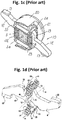
- the prior system is a compression spring based profile type contact system as shown in figure 1d .
- Fig 1a and 1d shows compression spring based shaft construction, where as Fig 1b and 1c shows extension spring based shaft construction.
- the arrangement shown in Fig 1a is a non flappable type of contact system. This causes the spring to continuously oppose the moving contact, thus reducing the efficiency of short circuit breaking.
- the arrangement shown in Fig 1b and 1c are profile based systems in which the springs apply contact pressure through cam action. This causes increased friction on the contacts, thus reducing the efficiency of short circuit breaking.
- the arrangement shown in Fig 1d is a compression spring based system. But the force is transferred to contact through cam action. This can lead to non stability of moving contact and can also increase friction.
- Fig.2 shows the variation of contact pressure with erosion for a conventional system. This decrease in contact pressure causes increased resistance between contacts. This causes problems of higher temperature rise in the breaker. This also increases the burden on other components in the breaker.
- the conventional technology for shaft construction uses an open shaft construction or partially closed construction.
- For rotation of moving contact with respect to the shaft there has to be an opening in the shaft with slot length depending on degree of rotation of moving contact. This produces the following problems:
- a spring arrangement can be uniquely designed in such a way that, for initial opening of contact system the spring force opposes the electromagnetic force and then after that aids the electromagnetic force. This arrangement helps in an increased opening velocity, which in turn helps in better breaking.
- the inventors have also found that in the newly designed double break contact system the contact pressure is maintained even after wear out of the contacts. This would help the breaker in maintaining the same level of performance even after erosion of contacts. Further the construction of the present invention has been provided with a movable shaft cover which rotates along with the moving contacts during repulsion when there is a short circuit.
- a basic object of the present invention is to overcome the disadvantages/drawbacks of the known art.
- Another object of the present invention is to provide an improved double break contact system for moulded case circuit breakers.
- Another object of the present invention is to provide a holder arrangement such that the system attains maximum stability.
- Another object is to provide minimal friction effect.
- an improved double break contact system for use in moulded case circuit breakers according to claim 1.
- Fig 3 shows the new MCCB contact system in ON condition.
- the current conduction happens through the fixed contact (1) onto the moving contact (3) and again to the second fixed contact (2).
- the compression spring (4) arranged between the holders (5) provide the contact force required to maintain the pressure between moving contacts (3) and fixed contacts (1 and 2) to desired levels.
- the contacts are designed (as in most of present MCCBs) in such a way that during short circuit conditions, an electromagnetic force acts between the moving contact and the fixed contacts. This force rotates the moving contact and brings it to repelled position as shown in Fig.4 .
- the fixed contact has been designed such that it helps in increasing the contact opening as compared to a conventional contact system. As shown separately in Fig.
- the fixed contacts (1 and 2) have a substantially U-shaped profile in which the contact portion which comes in contact with the moving contacts (3) comprises an inward bent portion (6).
- the holders (5) rotate on pins (7) mounted on the shaft (8).
- This arrangement provides easy rotation of holders and helps in channelizing the spring force exactly in the required direction.
- the moving contact is supported only by the holder arrangement. This enables moving contact to face minimal friction during movement.
- the arrangement of moving contact is shown in Fig.5 .
- This type of spring arrangement also enables the system to have a high contact opening than conventional systems.
- the shaft construction is also much simplified in this arrangement as compared to conventional systems.
- the arrangement of springs on the holder is shown in detail in Fig.14 .
- the holder arrangement as illustrated in Fig. 14 comprises two substantially rectangular sockets (9) having pins (10) located inside said sockets (9).
- the springs (4) are mounted on the said pins (10) and secured in the said sockets (9).
- the sockets (9) further comprise holes (11) at the top for pin mounting the holders on the shaft in a manner that holders are free to rotate on the shaft surface. It is to be noted in this context that the sockets have been described as rectangular in the present embodiment of the invention which should not be considered to be limiting scope of the invention.
- the shape of the sockets can be anything fulfilling the ergonomics of the other components/parts of the contact system.
- FIG.15 A different method of contact arrangement which is possible in this configuration is also shown in Fig.15 .
- This is a simpler arrangement as compared to the above mentioned concept, but needs more space for implementation.
- the contact systems are provided with limited space and therefore, the industry demands arrangements which can be functionally fitted in a specified space.
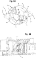
- Figure 8 shows enclosed shaft construction wherein the shaft cover (12) (also shown separately in Fig. 9 ) secures the shaft (8) and moving contact (3).
- the shaft cover (12) can be in the form of hollow cylinder with slots (13) for insertion of the moving contact (3).
- the shaft cover can be moulded out of flame retardant thermoplastic materials.
- the moving contact rotates with respect to the shaft. During this rotation, moving contact touches the shaft cover flaps (14) shown in Fig 9 , and thus rotates the shaft cover along with it.
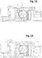
- the shaft cover flaps (14) shown in Fig 9 When the moving contact opens fully during repulsion as show in Fig 12 , the shaft cover completely encloses the shaft. If shaft cover is not present as shown in Fig 13 , the shaft leaves an open slot after the moving contact has repelled.
Landscapes
- Chemical & Material Sciences (AREA)
- Engineering & Computer Science (AREA)
- Composite Materials (AREA)
- Materials Engineering (AREA)
- Breakers (AREA)
- Physics & Mathematics (AREA)
- Electromagnetism (AREA)
Description
- The present invention generally relates to contact system for circuit breakers, mainly moulded case circuit breakers (MCCBs). More particularly, the invention is concerned about a contact system comprising a spring arrangement where the moving contact flips open during short circuit condition.
- Circuit breakers are used for switching and protection of electrical equipments. It consists mainly of current sensing means, mechanism and contact system. The contact system consists of a set of fixed contacts and a moving contact. During any fault (short-circuit) in the line, the moving contact is opens up and clears the fault. During ON condition, a set of springs provide contact force to maintain the moving contact in ON condition. Different arrangements of springs are followed currently for maintaining contact pressure.
- Nowadays the contact system is made in such a way that the moving contact repels open during any fault in line due to electromagnetic forces. During this movement the electromagnetic force has to fully act against the springs providing contact pressure.
- The different means of contact arrangement currently in use are shown in
Figs. 1(a) to 1(d) with reference to the prior patent documents. -
US5534832 discloses a switch having at least one power switching pole includes a contact bridge cooperating with fixed contacts and adapted to be maneuvered either by mobile parts of a solenoid or by a tripping mechanism. The contact bridge is rotatable and the mobile parts of the solenoid operate the contact bridge through the intermediary of a transmission mechanism. Referringfigure 1a it would be found that the contact system is compression spring based non flappable type. -
US5310971 discloses a molded case low voltage circuit breaker comprising a rotary contact bridge, a pair of stationary contacts cooperating with the contact bridge, current input conductors to the stationary contacts arranged to generate electrodynamic forces repelling the contact bridge to a repelled open position when a short-circuit occurs, a rotary bar having a transverse orifice housing with clearance the contact bridge which protrudes out from both sides of the bar, at least one pair of tension springs fitted between the bar and the contact bridge to provide a contact pressure of the contact bridge on the stationary contacts in closed position of the circuit breaker, while allowing rotation of the contact bridge to the repelled open position due to the electrodynamic forces. However, the system of the prior art is extension spring based. Reference is drawn tofigure 1b . -
US6870112 discloses a low-voltage circuit breaker that allows optimum execution of the electrical switching operations, allowing in particular to eliminate or at least minimize the possibility that in short-circuit conditions the moving contact bounces toward the fixed one, with consequent restriking of the electric arc, with a constructive structure that is simple and functionally effective and does not require additional latching elements during opening. The contact system described in this prior art document is extension spring and profile based as shown infigure 1c . -
US7394032 discloses an electrodynamically tilting contact system for power circuit breakers, especially for current-limiting circuit breakers, in which a breaker shaft segment, a rotary contact bridge pivotably mounted therein and contact force springs constitute components of a tilting snap-action mechanism that holds the rotary contact bridge in a repulsed position after the fixed contacts have been electrodynamically repulsed. The prior system is a compression spring based profile type contact system as shown infigure 1d . - The main limitations of the existing arrangements are:
- Most of the configurations have a continuously opposing spring force against the electromagnetic repulsion force giving less opening speed. (There is no flip locking)
- Contact pressure for most of the configurations is provided by extension springs which are comparatively complex in construction and less accurate. Also no flip locking is possible in simple construction using extension springs.
- The absence of flip locking in many of the configurations can result in contact not remaining in the final repelled condition after the fault has been cleared and current comes to zero.
- Even in cases where flip locking has been proposed the holding arrangement of springs are made in ways which could bring instability in contacts and increased friction occurs.
- All the above drawbacks of conventional arrangements also translate into lesser contact opening during a fault which makes clearing higher faults difficult. (If the contacts open more, more arc voltage is obtained which helps in easier fault clearance).
-
Fig 1a and1d shows compression spring based shaft construction, where asFig 1b and1c shows extension spring based shaft construction. The arrangement shown inFig 1a is a non flappable type of contact system. This causes the spring to continuously oppose the moving contact, thus reducing the efficiency of short circuit breaking. The arrangement shown inFig 1b and1c are profile based systems in which the springs apply contact pressure through cam action. This causes increased friction on the contacts, thus reducing the efficiency of short circuit breaking. The arrangement shown inFig 1d is a compression spring based system. But the force is transferred to contact through cam action. This can lead to non stability of moving contact and can also increase friction. - In a conventional system, when contact button wear out due to short circuit or normal switching, the contact springs adjust to push the contact further closing the contact. Due to this adjustment, a part of contact pressure is lost.
Fig.2 shows the variation of contact pressure with erosion for a conventional system. This decrease in contact pressure causes increased resistance between contacts. This causes problems of higher temperature rise in the breaker. This also increases the burden on other components in the breaker. - The conventional technology for shaft construction uses an open shaft construction or partially closed construction. For rotation of moving contact with respect to the shaft, there has to be an opening in the shaft with slot length depending on degree of rotation of moving contact. This produces the following problems:
- 1. During arcing hot gases and arc products are produced which can enter inside the shaft damaging the components like springs and pins inside the shaft.
- 2. An open construction leads to lesser differential pressure on arc, i.e. the pressure difference between the front and rear of arc will be lesser. Increased differential pressure is required for efficient driving of arc into the extinguishing zone.
- 3. An open shaft construction increases the chance of standing arc because of lesser insulation between the contacts.
- Therefore, there exists a need of a contact system comprising a spring arrangement where the moving contact flips open during short circuit condition. Further the contact system of the present invention would be able to address all the limitations of the prior art as discussed hereinabove.
-
US 7189935 B1 andDE 102011075655 A1 disclose break contact systems for use in moulded case circuit breakers having the characteristics of the preamble ofclaim 1. - The present inventors have found that a spring arrangement can be uniquely designed in such a way that, for initial opening of contact system the spring force opposes the electromagnetic force and then after that aids the electromagnetic force. This arrangement helps in an increased opening velocity, which in turn helps in better breaking. The inventors have also found that in the newly designed double break contact system the contact pressure is maintained even after wear out of the contacts. This would help the breaker in maintaining the same level of performance even after erosion of contacts. Further the construction of the present invention has been provided with a movable shaft cover which rotates along with the moving contacts during repulsion when there is a short circuit.
- A basic object of the present invention is to overcome the disadvantages/drawbacks of the known art.
- Another object of the present invention is to provide an improved double break contact system for moulded case circuit breakers.
- Another object of the present invention is to provide a holder arrangement such that the system attains maximum stability.
- Another object is to provide minimal friction effect.
- These and other advantages of the present invention will become readily apparent from the following detailed description read in conjunction with the accompanying drawings.
- The following presents a simplified summary of the invention in order to provide a basic understanding of some aspects of the invention. This summary is not an extensive overview of the present invention. It is not intended to identify the key/critical elements of the invention or to delineate the scope of the invention. Its sole purpose is to present some concept of the invention in a simplified form as a prelude to a more detailed description of the invention presented later.
- According to one aspect of the present invention there is provided an improved double break contact system for use in moulded case circuit breakers according to
claim 1. - So that those having ordinary skill in the art will more readily understand how to construct a contact system comprising a spring arrangement where the moving contact flips open during short circuit condition in accordance with the present disclosure, exemplary embodiments are described in details herein below with reference the accompanying drawings wherein:
-
Figs. 1a to 1d illustrate contact systems of the prior art. -
Fig 2 illustrates the variation of contact pressure with erosion for a conventional system. -
Fig 3 illustrates the double break contact system according to the present invention in ON condition for use in moulded case circuit breakers. -
Fig 4 illustrates the double break contact system according to the present invention in repelled condition. -
Fig 5 illustrates isometric view of the double break contact system of the present invention. -
Fig 6 illustrates the variation of contact pressure with erosion in the contact system of the present invention. -
Fig 7 illustrates the application of force on the spring arrangement of the contact system. -
Fig 8 illustrates enclosed shaft construction. -
Fig 9 illustrates shaft cover. -
Fig 10 illustrates one side open view of the enclosed shaft. -
Fig 11 illustrates a moulded circuit breaker with enclose shaft. -
Fig 12 illustrates a moulded circuit breaker with enclosed shaft with the moving contacts in repelled open position. -
Fig 13 illustrates a moulded circuit breaker without enclosed shaft with the moving contacts in repelled open position. -
Fig 14 illustrates the spring holder arrangement in the present invention. -
Fig 15 illustrates an optional spring holder arrangement which can be used in the contact system of the present invention. -
Fig 16 illustrates design of the fixed contact used in the contact system of the present invention. - The following drawings are illustrative of particular examples for enabling methods of the present invention, are descriptive of some of the methods, and are not intended to limit the scope of the invention. The drawings are not to scale (unless so stated) and are intended for use in conjunction with the explanations in the following detailed description.
-
Fig 3 shows the new MCCB contact system in ON condition. The current conduction happens through the fixed contact (1) onto the moving contact (3) and again to the second fixed contact (2). The compression spring (4) arranged between the holders (5) provide the contact force required to maintain the pressure between moving contacts (3) and fixed contacts (1 and 2) to desired levels. The contacts are designed (as in most of present MCCBs) in such a way that during short circuit conditions, an electromagnetic force acts between the moving contact and the fixed contacts. This force rotates the moving contact and brings it to repelled position as shown inFig.4 . In the present invention the fixed contact has been designed such that it helps in increasing the contact opening as compared to a conventional contact system. As shown separately inFig. 16 the fixed contacts (1 and 2) have a substantially U-shaped profile in which the contact portion which comes in contact with the moving contacts (3) comprises an inward bent portion (6). During the motion the holders (5) rotate on pins (7) mounted on the shaft (8). This arrangement provides easy rotation of holders and helps in channelizing the spring force exactly in the required direction. The moving contact is supported only by the holder arrangement. This enables moving contact to face minimal friction during movement. The arrangement of moving contact is shown inFig.5 . This type of spring arrangement also enables the system to have a high contact opening than conventional systems. The shaft construction is also much simplified in this arrangement as compared to conventional systems. - The arrangement of springs on the holder is shown in detail in
Fig.14 . The holder arrangement as illustrated inFig. 14 comprises two substantially rectangular sockets (9) having pins (10) located inside said sockets (9). The springs (4) are mounted on the said pins (10) and secured in the said sockets (9). The sockets (9) further comprise holes (11) at the top for pin mounting the holders on the shaft in a manner that holders are free to rotate on the shaft surface. It is to be noted in this context that the sockets have been described as rectangular in the present embodiment of the invention which should not be considered to be limiting scope of the invention. The shape of the sockets can be anything fulfilling the ergonomics of the other components/parts of the contact system. - A different method of contact arrangement which is possible in this configuration is also shown in
Fig.15 . This is a simpler arrangement as compared to the above mentioned concept, but needs more space for implementation. The contact systems are provided with limited space and therefore, the industry demands arrangements which can be functionally fitted in a specified space. - In ON condition torque due to spring by moving contact is transferred to contact pressure. As contacts wear, due to adjustment by springs, the spring force reduces. For keeping spring torque at the same value, the perpendicular distance form line of action of spring force to shaft centre should increase with erosion. This increase in length should produce a greater increment in torque than what is lost due to decrease in spring force. This is achieved by keeping the spring rate to the lowest possible value.
- As shown in
Fig.6 the contact pressure increases with erosion. - This gives the following advantages.
- 1. Improved thermal performance of the breaker due to improved contact pressure.
- 2. Higher electrical life of breaker due to the ability to perform after erosion.
- 3. Improved performance after short circuit due to the ability to perform even after erosion.
- 4. Chance to use less thick button giving option for material saving.
-
Figure 8 shows enclosed shaft construction wherein the shaft cover (12) (also shown separately inFig. 9 ) secures the shaft (8) and moving contact (3). The shaft cover (12) can be in the form of hollow cylinder with slots (13) for insertion of the moving contact (3). The shaft cover can be moulded out of flame retardant thermoplastic materials. - During repulsion, the moving contact rotates with respect to the shaft. During this rotation, moving contact touches the shaft cover flaps (14) shown in
Fig 9 , and thus rotates the shaft cover along with it. When the moving contact opens fully during repulsion as show inFig 12 , the shaft cover completely encloses the shaft. If shaft cover is not present as shown inFig 13 , the shaft leaves an open slot after the moving contact has repelled. - The closed construction provides the following advantages
- 1. It protects the inside components like springs and pins from hot gases and arc products during short circuit arcing.
- 2. It helps in developing higher pressure behind the arc due to closed region, thus driving the arc away from the shaft into the arc extinguishing region as shown in
Fig 12 . - 3. It acts as an insulation barrier between live parts during short circuit and prevents standing arc, thus helping the breaker in effective arc quenching. In
Fig 11 , there is a possibility of arcing between Points A and B during short circuit. The shaft cover stands as an insulation medium between the two points and hence nullifies the possibility of this arcing. - 4. When the moving repels open as shown in
Fig 12 , there is a chance of breakdown of air between Point C and Point D, which can lead to standing arc and hence short circuit failure. The shaft cover flap shown inFig 6 acts as an insulation barrier between these two points and hence prevents failure. - Although the embodiments herein are described with various specific embodiments, it will be obvious for a person skilled in the art to practice the embodiments herein with modifications. However, all such modifications are deemed to be within the scope of the claims.
- It is also to be understood that the following claims are intended to cover all of the generic and specific features of the embodiments described herein and all the statements of the scope of the embodiments which as a matter of language might be said to fall there between.
Claims (6)
- An improved double break contact system for use in moulded case circuit breakers, said double break contact system comprising :shaft means (8);fixed contact means (1, 2) and moving contact means (3), said moving contact means (3) being mounted on said shaft means (8) such that said moving contact means (3) rotate with respect to the movement of the shaft means (8);spring means (4) operatively mounted on the said shaft means (8);a holder arrangement (5, 7) comprising holder means (5) for securing said spring means (4);wherein said holder means (5) are rotatably mounted on said shaft means (8) in a manner that rotation of said shaft means (8) in operation rotates said holder means (5);wherein said spring means (4) are adapted to provide force opposing the electromagnetic force as well as force aiding the electromagnetic force; andwherein said fixed contacts means (1, 2) have a substantially U-shaped profile with a contact portion designed to be contacted by the moving contacts means (3);characterized in that- said contact portion of the U-shaped profile of the fixed contact means (1, 2) comprises an inward bent portion (6),- the contact system further comprises shaft cover means (12) for securing the shaft means (8) and the moving contact means (3), said shaft cover means (12) being in the form of a hollow cylinder having a circumferential wall, said circumferential wall comprising slot means (13) through which the moving contact means (3) protrude outside the shaft cover means (12), and- said shaft cover means (12) further comprise a plurality of shaft cover flap means (14) projecting outwardly from said circumferential wall, in such a way that, when a moving contact means (3) rotates with respect to the shaft means (8), the moving contact means (3) touches a respective shaft cover flap means (14), thereby causing rotation of the shaft cover means (12).
- Contact system as claimed in claim 1, wherein said spring means are compression springs (4).
- Contact system as claimed in claim 2, wherein said holder means (5) comprise two socket means (9) for accommodating one said compression spring (4) therebetween, a pin (10) being located inside each socket means (9), on which a respective end of said compression spring (4) is mounted, to secure the compression spring (4) between the two socket means (9).
- Contact system as claimed in claim 1, wherein the holder arrangement (5, 7) further comprises pin means (7) adapted for mounting said holder means (5) on the shaft means (8) in a manner that the said spring means (4) are rotatable with the rotation of said shaft means (8), thereby channelizing the spring force exactly in the required direction.
- Contact system as claimed in claims 3 and 4, wherein each socket means (9) further comprises a hole (11) at the top thereof and extending in a transverse direction relative to the pin (10), for mounting the holders means (5) on the shaft means (8) via said pin means (7) in a manner that the holders means (5) are free to rotate on the surface of the shaft means (8).
- Contact system as claimed in claim 1, wherein the shaft cover means (12) is moulded out of a flame retardant thermoplastic material.
Applications Claiming Priority (2)
| Application Number | Priority Date | Filing Date | Title |
|---|---|---|---|
| IN911MU2012 | 2012-03-28 | ||
| PCT/IB2012/054707 WO2013144686A1 (en) | 2012-03-28 | 2012-09-11 | An improved double break contact system for moulded case circuit breakers |
Publications (2)
| Publication Number | Publication Date |
|---|---|
| EP2831897A1 EP2831897A1 (en) | 2015-02-04 |
| EP2831897B1 true EP2831897B1 (en) | 2017-03-01 |
Family
ID=47076300
Family Applications (1)
| Application Number | Title | Priority Date | Filing Date |
|---|---|---|---|
| EP12778426.2A Active EP2831897B1 (en) | 2012-03-28 | 2012-09-11 | An improved double break contact system for moulded case circuit breakers |
Country Status (3)
| Country | Link |
|---|---|
| US (1) | US9508495B2 (en) |
| EP (1) | EP2831897B1 (en) |
| WO (1) | WO2013144686A1 (en) |
Families Citing this family (1)
| Publication number | Priority date | Publication date | Assignee | Title |
|---|---|---|---|---|
| EP3916745B1 (en) * | 2020-05-28 | 2024-03-13 | ABB Schweiz AG | Electrical switch |
Citations (4)
| Publication number | Priority date | Publication date | Assignee | Title |
|---|---|---|---|---|
| US6184761B1 (en) * | 1999-12-20 | 2001-02-06 | General Electric Company | Circuit breaker rotary contact arrangement |
| US20020010243A1 (en) * | 1994-12-19 | 2002-01-24 | Shunichi Katsube | Organic and inorganic complex compound and switch using same |
| US20060077022A1 (en) * | 2004-10-07 | 2006-04-13 | Ls Industrial Systems Co., Ltd. | Contactor assembly for a circuit breaker |
| EP2081202A2 (en) * | 2008-01-16 | 2009-07-22 | Siemens Aktiengesellschaft | Switching device, in particular circuit breaker |
Family Cites Families (11)
| Publication number | Priority date | Publication date | Assignee | Title |
|---|---|---|---|---|
| FR2622347B1 (en) * | 1987-10-26 | 1995-04-14 | Merlin Gerin | CUTTING DEVICE FOR A MULTIPOLAR CIRCUIT BREAKER WITH DOUBLE ROTARY CONTACT |
| FR2688626B1 (en) | 1992-03-13 | 1994-05-06 | Merlin Gerin | CIRCUIT BREAKER WITH MOLDED BOX WITH BRIDGE OF BRAKE CONTACTS AT THE END OF PULSE STROKE. |
| EP0617449B1 (en) | 1993-03-25 | 1997-10-22 | Schneider Electric Sa | Switching apparatus |
| IT1289482B1 (en) * | 1996-12-20 | 1998-10-15 | Sace Spa | CURRENT SWITCH WITH MOVABLE CONTACTS |
| DE10144105C1 (en) * | 2001-09-03 | 2003-04-17 | Siemens Ag | Switch contact arrangement with a spring force acting in the closing direction and in the opening direction |
| ITMI20012325A1 (en) | 2001-11-06 | 2003-05-06 | Abb Service Srl | LOW VOLTAGE SWITCH |
| DE10358828A1 (en) | 2003-12-16 | 2005-07-14 | Moeller Gmbh | Electrodynamically tilting contact system for circuit breakers |
| US7189935B1 (en) * | 2005-12-08 | 2007-03-13 | General Electric Company | Contact arm apparatus and method of assembly thereof |
| US7800007B2 (en) * | 2007-06-26 | 2010-09-21 | General Electric Company | Circuit breaker subassembly apparatus |
| DE102007040163A1 (en) * | 2007-08-21 | 2009-02-26 | Siemens Ag | Switching device with a switching shaft for mounting a rotary contact bridge and multi-pole switching device arrangement |
| CN102262983B (en) * | 2010-05-28 | 2014-12-31 | 西门子公司 | Rotating contact terminal component |
-
2012
- 2012-09-11 WO PCT/IB2012/054707 patent/WO2013144686A1/en active Application Filing
- 2012-09-11 US US14/388,858 patent/US9508495B2/en active Active
- 2012-09-11 EP EP12778426.2A patent/EP2831897B1/en active Active
Patent Citations (4)
| Publication number | Priority date | Publication date | Assignee | Title |
|---|---|---|---|---|
| US20020010243A1 (en) * | 1994-12-19 | 2002-01-24 | Shunichi Katsube | Organic and inorganic complex compound and switch using same |
| US6184761B1 (en) * | 1999-12-20 | 2001-02-06 | General Electric Company | Circuit breaker rotary contact arrangement |
| US20060077022A1 (en) * | 2004-10-07 | 2006-04-13 | Ls Industrial Systems Co., Ltd. | Contactor assembly for a circuit breaker |
| EP2081202A2 (en) * | 2008-01-16 | 2009-07-22 | Siemens Aktiengesellschaft | Switching device, in particular circuit breaker |
Also Published As
| Publication number | Publication date |
|---|---|
| US9508495B2 (en) | 2016-11-29 |
| EP2831897A1 (en) | 2015-02-04 |
| US20150077199A1 (en) | 2015-03-19 |
| WO2013144686A1 (en) | 2013-10-03 |
Similar Documents
| Publication | Publication Date | Title |
|---|---|---|
| US8159319B2 (en) | Double-breaking contact system for a low voltage circuit breaker, a molded case circuit breaker comprising the double-breaking contact system, and a method for breaking a circuit | |
| KR200393296Y1 (en) | Arc chamber for circuit breaker | |
| KR200477246Y1 (en) | A circuit braker | |
| CN100555507C (en) | Miniature circuit breaker | |
| CN101083187A (en) | Circuit breaker | |
| KR100978270B1 (en) | Current limiter of circuit breaker | |
| PL198718B1 (en) | Arcing contact arrangement | |
| EP2831897B1 (en) | An improved double break contact system for moulded case circuit breakers | |
| KR20050101248A (en) | A movable contactor assembly for a mould cased circuit breaker | |
| KR100676968B1 (en) | A contactor assembly for a current limitable circuit breaker | |
| US9412549B2 (en) | Electromagnetically enhanced contact separation in a circuit breaker | |
| JP4960072B2 (en) | Circuit breaker | |
| KR101232453B1 (en) | Circuit breaker | |
| KR101036485B1 (en) | Contactor assembly for current limitable circuit breaker | |
| KR100990256B1 (en) | Auxiliary device for four poles mold cased circuit breker and four poles mold cased circuit breaker having the same | |
| EP2110827A2 (en) | Circuit breaker with improved close and latch performance | |
| JP5810835B2 (en) | Circuit breaker | |
| JP4776638B2 (en) | Circuit breaker | |
| CA2894939C (en) | Electrical switching apparatus and link assembly therefor | |
| CN113936977A (en) | Breaking unit of double-breakpoint molded case circuit breaker | |
| CN220651928U (en) | Arc breaking structure of universal circuit breaker | |
| CN101170031A (en) | Quick break low voltage circuit breaker | |
| EP3772078B1 (en) | An electrode for a circuit breaker and the circuit breaker | |
| KR101704989B1 (en) | Movable contact of circuit breaker | |
| CN107808806B (en) | Turnable movable contact component and switching device |
Legal Events
| Date | Code | Title | Description |
|---|---|---|---|
| PUAI | Public reference made under article 153(3) epc to a published international application that has entered the european phase |
Free format text: ORIGINAL CODE: 0009012 |
|
| 17P | Request for examination filed |
Effective date: 20141013 |
|
| AK | Designated contracting states |
Kind code of ref document: A1 Designated state(s): AL AT BE BG CH CY CZ DE DK EE ES FI FR GB GR HR HU IE IS IT LI LT LU LV MC MK MT NL NO PL PT RO RS SE SI SK SM TR |
|
| AX | Request for extension of the european patent |
Extension state: BA ME |
|
| DAX | Request for extension of the european patent (deleted) | ||
| 17Q | First examination report despatched |
Effective date: 20160421 |
|
| GRAP | Despatch of communication of intention to grant a patent |
Free format text: ORIGINAL CODE: EPIDOSNIGR1 |
|
| INTG | Intention to grant announced |
Effective date: 20160922 |
|
| RIN1 | Information on inventor provided before grant (corrected) |
Inventor name: GUPTA, MUKUL Inventor name: PHILIP, ANOOP |
|
| GRAS | Grant fee paid |
Free format text: ORIGINAL CODE: EPIDOSNIGR3 |
|
| GRAA | (expected) grant |
Free format text: ORIGINAL CODE: 0009210 |
|
| AK | Designated contracting states |
Kind code of ref document: B1 Designated state(s): AL AT BE BG CH CY CZ DE DK EE ES FI FR GB GR HR HU IE IS IT LI LT LU LV MC MK MT NL NO PL PT RO RS SE SI SK SM TR |
|
| REG | Reference to a national code |
Ref country code: GB Ref legal event code: FG4D |
|
| REG | Reference to a national code |
Ref country code: CH Ref legal event code: EP Ref country code: AT Ref legal event code: REF Ref document number: 872202 Country of ref document: AT Kind code of ref document: T Effective date: 20170315 |
|
| REG | Reference to a national code |
Ref country code: IE Ref legal event code: FG4D |
|
| REG | Reference to a national code |
Ref country code: DE Ref legal event code: R096 Ref document number: 602012029288 Country of ref document: DE |
|
| REG | Reference to a national code |
Ref country code: NL Ref legal event code: MP Effective date: 20170301 |
|
| REG | Reference to a national code |
Ref country code: LT Ref legal event code: MG4D |
|
| REG | Reference to a national code |
Ref country code: AT Ref legal event code: MK05 Ref document number: 872202 Country of ref document: AT Kind code of ref document: T Effective date: 20170301 |
|
| PG25 | Lapsed in a contracting state [announced via postgrant information from national office to epo] |
Ref country code: LT Free format text: LAPSE BECAUSE OF FAILURE TO SUBMIT A TRANSLATION OF THE DESCRIPTION OR TO PAY THE FEE WITHIN THE PRESCRIBED TIME-LIMIT Effective date: 20170301 Ref country code: GR Free format text: LAPSE BECAUSE OF FAILURE TO SUBMIT A TRANSLATION OF THE DESCRIPTION OR TO PAY THE FEE WITHIN THE PRESCRIBED TIME-LIMIT Effective date: 20170602 Ref country code: FI Free format text: LAPSE BECAUSE OF FAILURE TO SUBMIT A TRANSLATION OF THE DESCRIPTION OR TO PAY THE FEE WITHIN THE PRESCRIBED TIME-LIMIT Effective date: 20170301 Ref country code: NO Free format text: LAPSE BECAUSE OF FAILURE TO SUBMIT A TRANSLATION OF THE DESCRIPTION OR TO PAY THE FEE WITHIN THE PRESCRIBED TIME-LIMIT Effective date: 20170601 Ref country code: HR Free format text: LAPSE BECAUSE OF FAILURE TO SUBMIT A TRANSLATION OF THE DESCRIPTION OR TO PAY THE FEE WITHIN THE PRESCRIBED TIME-LIMIT Effective date: 20170301 |
|
| PG25 | Lapsed in a contracting state [announced via postgrant information from national office to epo] |
Ref country code: BG Free format text: LAPSE BECAUSE OF FAILURE TO SUBMIT A TRANSLATION OF THE DESCRIPTION OR TO PAY THE FEE WITHIN THE PRESCRIBED TIME-LIMIT Effective date: 20170601 Ref country code: RS Free format text: LAPSE BECAUSE OF FAILURE TO SUBMIT A TRANSLATION OF THE DESCRIPTION OR TO PAY THE FEE WITHIN THE PRESCRIBED TIME-LIMIT Effective date: 20170301 Ref country code: AT Free format text: LAPSE BECAUSE OF FAILURE TO SUBMIT A TRANSLATION OF THE DESCRIPTION OR TO PAY THE FEE WITHIN THE PRESCRIBED TIME-LIMIT Effective date: 20170301 Ref country code: ES Free format text: LAPSE BECAUSE OF FAILURE TO SUBMIT A TRANSLATION OF THE DESCRIPTION OR TO PAY THE FEE WITHIN THE PRESCRIBED TIME-LIMIT Effective date: 20170301 Ref country code: LV Free format text: LAPSE BECAUSE OF FAILURE TO SUBMIT A TRANSLATION OF THE DESCRIPTION OR TO PAY THE FEE WITHIN THE PRESCRIBED TIME-LIMIT Effective date: 20170301 Ref country code: SE Free format text: LAPSE BECAUSE OF FAILURE TO SUBMIT A TRANSLATION OF THE DESCRIPTION OR TO PAY THE FEE WITHIN THE PRESCRIBED TIME-LIMIT Effective date: 20170301 |
|
| PG25 | Lapsed in a contracting state [announced via postgrant information from national office to epo] |
Ref country code: NL Free format text: LAPSE BECAUSE OF FAILURE TO SUBMIT A TRANSLATION OF THE DESCRIPTION OR TO PAY THE FEE WITHIN THE PRESCRIBED TIME-LIMIT Effective date: 20170301 |
|
| PG25 | Lapsed in a contracting state [announced via postgrant information from national office to epo] |
Ref country code: EE Free format text: LAPSE BECAUSE OF FAILURE TO SUBMIT A TRANSLATION OF THE DESCRIPTION OR TO PAY THE FEE WITHIN THE PRESCRIBED TIME-LIMIT Effective date: 20170301 Ref country code: RO Free format text: LAPSE BECAUSE OF FAILURE TO SUBMIT A TRANSLATION OF THE DESCRIPTION OR TO PAY THE FEE WITHIN THE PRESCRIBED TIME-LIMIT Effective date: 20170301 Ref country code: IT Free format text: LAPSE BECAUSE OF FAILURE TO SUBMIT A TRANSLATION OF THE DESCRIPTION OR TO PAY THE FEE WITHIN THE PRESCRIBED TIME-LIMIT Effective date: 20170301 Ref country code: CZ Free format text: LAPSE BECAUSE OF FAILURE TO SUBMIT A TRANSLATION OF THE DESCRIPTION OR TO PAY THE FEE WITHIN THE PRESCRIBED TIME-LIMIT Effective date: 20170301 Ref country code: SK Free format text: LAPSE BECAUSE OF FAILURE TO SUBMIT A TRANSLATION OF THE DESCRIPTION OR TO PAY THE FEE WITHIN THE PRESCRIBED TIME-LIMIT Effective date: 20170301 |
|
| PG25 | Lapsed in a contracting state [announced via postgrant information from national office to epo] |
Ref country code: IS Free format text: LAPSE BECAUSE OF FAILURE TO SUBMIT A TRANSLATION OF THE DESCRIPTION OR TO PAY THE FEE WITHIN THE PRESCRIBED TIME-LIMIT Effective date: 20170701 Ref country code: SM Free format text: LAPSE BECAUSE OF FAILURE TO SUBMIT A TRANSLATION OF THE DESCRIPTION OR TO PAY THE FEE WITHIN THE PRESCRIBED TIME-LIMIT Effective date: 20170301 Ref country code: PT Free format text: LAPSE BECAUSE OF FAILURE TO SUBMIT A TRANSLATION OF THE DESCRIPTION OR TO PAY THE FEE WITHIN THE PRESCRIBED TIME-LIMIT Effective date: 20170703 Ref country code: PL Free format text: LAPSE BECAUSE OF FAILURE TO SUBMIT A TRANSLATION OF THE DESCRIPTION OR TO PAY THE FEE WITHIN THE PRESCRIBED TIME-LIMIT Effective date: 20170301 |
|
| REG | Reference to a national code |
Ref country code: DE Ref legal event code: R097 Ref document number: 602012029288 Country of ref document: DE |
|
| PLBE | No opposition filed within time limit |
Free format text: ORIGINAL CODE: 0009261 |
|
| STAA | Information on the status of an ep patent application or granted ep patent |
Free format text: STATUS: NO OPPOSITION FILED WITHIN TIME LIMIT |
|
| PG25 | Lapsed in a contracting state [announced via postgrant information from national office to epo] |
Ref country code: DK Free format text: LAPSE BECAUSE OF FAILURE TO SUBMIT A TRANSLATION OF THE DESCRIPTION OR TO PAY THE FEE WITHIN THE PRESCRIBED TIME-LIMIT Effective date: 20170301 |
|
| 26N | No opposition filed |
Effective date: 20171204 |
|
| PG25 | Lapsed in a contracting state [announced via postgrant information from national office to epo] |
Ref country code: SI Free format text: LAPSE BECAUSE OF FAILURE TO SUBMIT A TRANSLATION OF THE DESCRIPTION OR TO PAY THE FEE WITHIN THE PRESCRIBED TIME-LIMIT Effective date: 20170301 |
|
| REG | Reference to a national code |
Ref country code: CH Ref legal event code: PL |
|
| PG25 | Lapsed in a contracting state [announced via postgrant information from national office to epo] |
Ref country code: MC Free format text: LAPSE BECAUSE OF FAILURE TO SUBMIT A TRANSLATION OF THE DESCRIPTION OR TO PAY THE FEE WITHIN THE PRESCRIBED TIME-LIMIT Effective date: 20170301 |
|
| REG | Reference to a national code |
Ref country code: IE Ref legal event code: MM4A |
|
| REG | Reference to a national code |
Ref country code: BE Ref legal event code: MM Effective date: 20170930 |
|
| PG25 | Lapsed in a contracting state [announced via postgrant information from national office to epo] |
Ref country code: LU Free format text: LAPSE BECAUSE OF NON-PAYMENT OF DUE FEES Effective date: 20170911 |
|
| REG | Reference to a national code |
Ref country code: FR Ref legal event code: ST Effective date: 20180531 |
|
| PG25 | Lapsed in a contracting state [announced via postgrant information from national office to epo] |
Ref country code: IE Free format text: LAPSE BECAUSE OF NON-PAYMENT OF DUE FEES Effective date: 20170911 Ref country code: CH Free format text: LAPSE BECAUSE OF NON-PAYMENT OF DUE FEES Effective date: 20170930 Ref country code: LI Free format text: LAPSE BECAUSE OF NON-PAYMENT OF DUE FEES Effective date: 20170930 |
|
| PG25 | Lapsed in a contracting state [announced via postgrant information from national office to epo] |
Ref country code: BE Free format text: LAPSE BECAUSE OF NON-PAYMENT OF DUE FEES Effective date: 20170930 Ref country code: FR Free format text: LAPSE BECAUSE OF NON-PAYMENT OF DUE FEES Effective date: 20171002 |
|
| PG25 | Lapsed in a contracting state [announced via postgrant information from national office to epo] |
Ref country code: MT Free format text: LAPSE BECAUSE OF NON-PAYMENT OF DUE FEES Effective date: 20170911 |
|
| PG25 | Lapsed in a contracting state [announced via postgrant information from national office to epo] |
Ref country code: HU Free format text: LAPSE BECAUSE OF FAILURE TO SUBMIT A TRANSLATION OF THE DESCRIPTION OR TO PAY THE FEE WITHIN THE PRESCRIBED TIME-LIMIT; INVALID AB INITIO Effective date: 20120911 |
|
| PG25 | Lapsed in a contracting state [announced via postgrant information from national office to epo] |
Ref country code: CY Free format text: LAPSE BECAUSE OF FAILURE TO SUBMIT A TRANSLATION OF THE DESCRIPTION OR TO PAY THE FEE WITHIN THE PRESCRIBED TIME-LIMIT Effective date: 20170301 |
|
| PG25 | Lapsed in a contracting state [announced via postgrant information from national office to epo] |
Ref country code: MK Free format text: LAPSE BECAUSE OF FAILURE TO SUBMIT A TRANSLATION OF THE DESCRIPTION OR TO PAY THE FEE WITHIN THE PRESCRIBED TIME-LIMIT Effective date: 20170301 |
|
| PG25 | Lapsed in a contracting state [announced via postgrant information from national office to epo] |
Ref country code: TR Free format text: LAPSE BECAUSE OF FAILURE TO SUBMIT A TRANSLATION OF THE DESCRIPTION OR TO PAY THE FEE WITHIN THE PRESCRIBED TIME-LIMIT Effective date: 20170301 |
|
| PG25 | Lapsed in a contracting state [announced via postgrant information from national office to epo] |
Ref country code: AL Free format text: LAPSE BECAUSE OF FAILURE TO SUBMIT A TRANSLATION OF THE DESCRIPTION OR TO PAY THE FEE WITHIN THE PRESCRIBED TIME-LIMIT Effective date: 20170301 |
|
| REG | Reference to a national code |
Ref country code: DE Ref legal event code: R082 Ref document number: 602012029288 Country of ref document: DE Representative=s name: TER MEER STEINMEISTER & PARTNER PATENTANWAELTE, DE Ref country code: DE Ref legal event code: R081 Ref document number: 602012029288 Country of ref document: DE Owner name: SCHNEIDER ELECTRIC INDIA PRIVATE LIMITED, IN Free format text: FORMER OWNER: LARSEN & TOUBRO LTD., MUMBAI, IN |
|
| REG | Reference to a national code |
Ref country code: GB Ref legal event code: 732E Free format text: REGISTERED BETWEEN 20210701 AND 20210707 |
|
| PGFP | Annual fee paid to national office [announced via postgrant information from national office to epo] |
Ref country code: GB Payment date: 20230728 Year of fee payment: 12 |
|
| PGFP | Annual fee paid to national office [announced via postgrant information from national office to epo] |
Ref country code: DE Payment date: 20230803 Year of fee payment: 12 |