EP2831220B1 - Améliorations de microplaques - Google Patents
Améliorations de microplaques Download PDFInfo
- Publication number
- EP2831220B1 EP2831220B1 EP13769204.2A EP13769204A EP2831220B1 EP 2831220 B1 EP2831220 B1 EP 2831220B1 EP 13769204 A EP13769204 A EP 13769204A EP 2831220 B1 EP2831220 B1 EP 2831220B1
- Authority
- EP
- European Patent Office
- Prior art keywords
- well
- liquid
- microplate
- ledge
- liquid retention
- Prior art date
- Legal status (The legal status is an assumption and is not a legal conclusion. Google has not performed a legal analysis and makes no representation as to the accuracy of the status listed.)
- Active
Links
- 239000007788 liquid Substances 0.000 claims description 181
- 238000004891 communication Methods 0.000 claims description 41
- 230000014759 maintenance of location Effects 0.000 claims description 35
- 238000011049 filling Methods 0.000 claims description 30
- 238000012546 transfer Methods 0.000 claims description 22
- 230000001133 acceleration Effects 0.000 claims description 20
- 230000004888 barrier function Effects 0.000 claims description 8
- 230000015572 biosynthetic process Effects 0.000 claims description 5
- 230000005764 inhibitory process Effects 0.000 claims description 2
- 230000000630 rising effect Effects 0.000 claims description 2
- 230000002265 prevention Effects 0.000 claims 4
- 238000000926 separation method Methods 0.000 claims 4
- 108090000623 proteins and genes Proteins 0.000 description 35
- 102000004169 proteins and genes Human genes 0.000 description 35
- 239000013078 crystal Substances 0.000 description 32
- 238000002425 crystallisation Methods 0.000 description 27
- 230000008025 crystallization Effects 0.000 description 27
- 238000007789 sealing Methods 0.000 description 22
- 239000010408 film Substances 0.000 description 21
- 239000000243 solution Substances 0.000 description 19
- 238000002474 experimental method Methods 0.000 description 17
- XLYOFNOQVPJJNP-UHFFFAOYSA-N water Chemical compound O XLYOFNOQVPJJNP-UHFFFAOYSA-N 0.000 description 17
- 239000012530 fluid Substances 0.000 description 13
- 238000011067 equilibration Methods 0.000 description 9
- 230000002829 reductive effect Effects 0.000 description 9
- 101001017516 Drosophila melanogaster Muscle segmentation homeobox Proteins 0.000 description 8
- 238000009792 diffusion process Methods 0.000 description 8
- 238000001704 evaporation Methods 0.000 description 8
- 238000007689 inspection Methods 0.000 description 8
- 230000007480 spreading Effects 0.000 description 8
- 230000008020 evaporation Effects 0.000 description 7
- 239000000463 material Substances 0.000 description 7
- 238000002156 mixing Methods 0.000 description 7
- 230000000694 effects Effects 0.000 description 6
- 239000004033 plastic Substances 0.000 description 6
- 229920003023 plastic Polymers 0.000 description 6
- 238000003860 storage Methods 0.000 description 6
- 239000007864 aqueous solution Substances 0.000 description 5
- 238000013461 design Methods 0.000 description 5
- 230000002706 hydrostatic effect Effects 0.000 description 5
- 238000000034 method Methods 0.000 description 5
- 230000006911 nucleation Effects 0.000 description 5
- 238000010899 nucleation Methods 0.000 description 5
- 239000012460 protein solution Substances 0.000 description 5
- 150000001298 alcohols Chemical class 0.000 description 4
- 238000002347 injection Methods 0.000 description 4
- 239000007924 injection Substances 0.000 description 4
- 230000005499 meniscus Effects 0.000 description 4
- 150000003839 salts Chemical class 0.000 description 4
- 238000012216 screening Methods 0.000 description 4
- PEDCQBHIVMGVHV-UHFFFAOYSA-N Glycerine Chemical compound OCC(O)CO PEDCQBHIVMGVHV-UHFFFAOYSA-N 0.000 description 3
- 229920006328 Styrofoam Polymers 0.000 description 3
- 238000002441 X-ray diffraction Methods 0.000 description 3
- 238000013459 approach Methods 0.000 description 3
- 239000006260 foam Substances 0.000 description 3
- 238000011065 in-situ storage Methods 0.000 description 3
- 230000002401 inhibitory effect Effects 0.000 description 3
- 238000001746 injection moulding Methods 0.000 description 3
- 229920006255 plastic film Polymers 0.000 description 3
- 239000002985 plastic film Substances 0.000 description 3
- 229920001223 polyethylene glycol Polymers 0.000 description 3
- 239000008261 styrofoam Substances 0.000 description 3
- 238000002424 x-ray crystallography Methods 0.000 description 3
- 229920000089 Cyclic olefin copolymer Polymers 0.000 description 2
- 239000004713 Cyclic olefin copolymer Substances 0.000 description 2
- KFZMGEQAYNKOFK-UHFFFAOYSA-N Isopropanol Chemical compound CC(C)O KFZMGEQAYNKOFK-UHFFFAOYSA-N 0.000 description 2
- 241000700605 Viruses Species 0.000 description 2
- 239000012062 aqueous buffer Substances 0.000 description 2
- 238000013480 data collection Methods 0.000 description 2
- 238000002050 diffraction method Methods 0.000 description 2
- 230000002349 favourable effect Effects 0.000 description 2
- 239000011521 glass Substances 0.000 description 2
- 230000000670 limiting effect Effects 0.000 description 2
- 238000011068 loading method Methods 0.000 description 2
- 239000000203 mixture Substances 0.000 description 2
- 238000000465 moulding Methods 0.000 description 2
- 238000001556 precipitation Methods 0.000 description 2
- 230000004044 response Effects 0.000 description 2
- 239000000523 sample Substances 0.000 description 2
- 239000013049 sediment Substances 0.000 description 2
- 239000007787 solid Substances 0.000 description 2
- 230000001052 transient effect Effects 0.000 description 2
- 238000009736 wetting Methods 0.000 description 2
- 241000579895 Chlorostilbon Species 0.000 description 1
- VGGSQFUCUMXWEO-UHFFFAOYSA-N Ethene Chemical compound C=C VGGSQFUCUMXWEO-UHFFFAOYSA-N 0.000 description 1
- 239000005977 Ethylene Substances 0.000 description 1
- 238000004566 IR spectroscopy Methods 0.000 description 1
- 239000004677 Nylon Substances 0.000 description 1
- 241000158500 Platanus racemosa Species 0.000 description 1
- 239000002202 Polyethylene glycol Substances 0.000 description 1
- 239000000654 additive Substances 0.000 description 1
- 238000000429 assembly Methods 0.000 description 1
- 230000000712 assembly Effects 0.000 description 1
- 238000005452 bending Methods 0.000 description 1
- 230000008901 benefit Effects 0.000 description 1
- 230000015556 catabolic process Effects 0.000 description 1
- 230000009194 climbing Effects 0.000 description 1
- 230000006835 compression Effects 0.000 description 1
- 238000007906 compression Methods 0.000 description 1
- 238000009833 condensation Methods 0.000 description 1
- 230000005494 condensation Effects 0.000 description 1
- 239000002577 cryoprotective agent Substances 0.000 description 1
- 230000001351 cycling effect Effects 0.000 description 1
- 238000006731 degradation reaction Methods 0.000 description 1
- 238000001514 detection method Methods 0.000 description 1
- 239000003599 detergent Substances 0.000 description 1
- 238000011161 development Methods 0.000 description 1
- 238000006073 displacement reaction Methods 0.000 description 1
- 239000003814 drug Substances 0.000 description 1
- 229940079593 drug Drugs 0.000 description 1
- 229910052876 emerald Inorganic materials 0.000 description 1
- 239000010976 emerald Substances 0.000 description 1
- 238000005516 engineering process Methods 0.000 description 1
- 238000007710 freezing Methods 0.000 description 1
- 230000008014 freezing Effects 0.000 description 1
- 230000005484 gravity Effects 0.000 description 1
- 238000003306 harvesting Methods 0.000 description 1
- 230000002209 hydrophobic effect Effects 0.000 description 1
- 238000005286 illumination Methods 0.000 description 1
- 230000002045 lasting effect Effects 0.000 description 1
- 229920002521 macromolecule Polymers 0.000 description 1
- 238000005259 measurement Methods 0.000 description 1
- 230000007246 mechanism Effects 0.000 description 1
- 239000002184 metal Substances 0.000 description 1
- 239000012229 microporous material Substances 0.000 description 1
- 238000012986 modification Methods 0.000 description 1
- 230000004048 modification Effects 0.000 description 1
- 108020004707 nucleic acids Proteins 0.000 description 1
- 102000039446 nucleic acids Human genes 0.000 description 1
- 150000007523 nucleic acids Chemical class 0.000 description 1
- 229920001778 nylon Polymers 0.000 description 1
- 150000002894 organic compounds Chemical class 0.000 description 1
- 230000001151 other effect Effects 0.000 description 1
- 230000003647 oxidation Effects 0.000 description 1
- 238000007254 oxidation reaction Methods 0.000 description 1
- 238000004806 packaging method and process Methods 0.000 description 1
- 230000035699 permeability Effects 0.000 description 1
- 229920006254 polymer film Polymers 0.000 description 1
- 239000002244 precipitate Substances 0.000 description 1
- 230000008569 process Effects 0.000 description 1
- 230000001737 promoting effect Effects 0.000 description 1
- 238000011160 research Methods 0.000 description 1
- -1 small molecule compounds Chemical class 0.000 description 1
- 230000003068 static effect Effects 0.000 description 1
- 238000012360 testing method Methods 0.000 description 1
- 239000010409 thin film Substances 0.000 description 1
- 238000000870 ultraviolet spectroscopy Methods 0.000 description 1
- 238000013022 venting Methods 0.000 description 1
Images


Classifications
-
- B—PERFORMING OPERATIONS; TRANSPORTING
- B01—PHYSICAL OR CHEMICAL PROCESSES OR APPARATUS IN GENERAL
- B01L—CHEMICAL OR PHYSICAL LABORATORY APPARATUS FOR GENERAL USE
- B01L3/00—Containers or dishes for laboratory use, e.g. laboratory glassware; Droppers
- B01L3/50—Containers for the purpose of retaining a material to be analysed, e.g. test tubes
- B01L3/508—Containers for the purpose of retaining a material to be analysed, e.g. test tubes rigid containers not provided for above
- B01L3/5085—Containers for the purpose of retaining a material to be analysed, e.g. test tubes rigid containers not provided for above for multiple samples, e.g. microtitration plates
-
- C—CHEMISTRY; METALLURGY
- C07—ORGANIC CHEMISTRY
- C07K—PEPTIDES
- C07K1/00—General methods for the preparation of peptides, i.e. processes for the organic chemical preparation of peptides or proteins of any length
- C07K1/14—Extraction; Separation; Purification
- C07K1/30—Extraction; Separation; Purification by precipitation
- C07K1/306—Extraction; Separation; Purification by precipitation by crystallization
-
- C—CHEMISTRY; METALLURGY
- C12—BIOCHEMISTRY; BEER; SPIRITS; WINE; VINEGAR; MICROBIOLOGY; ENZYMOLOGY; MUTATION OR GENETIC ENGINEERING
- C12M—APPARATUS FOR ENZYMOLOGY OR MICROBIOLOGY; APPARATUS FOR CULTURING MICROORGANISMS FOR PRODUCING BIOMASS, FOR GROWING CELLS OR FOR OBTAINING FERMENTATION OR METABOLIC PRODUCTS, i.e. BIOREACTORS OR FERMENTERS
- C12M23/00—Constructional details, e.g. recesses, hinges
- C12M23/02—Form or structure of the vessel
- C12M23/12—Well or multiwell plates
-
- C—CHEMISTRY; METALLURGY
- C30—CRYSTAL GROWTH
- C30B—SINGLE-CRYSTAL GROWTH; UNIDIRECTIONAL SOLIDIFICATION OF EUTECTIC MATERIAL OR UNIDIRECTIONAL DEMIXING OF EUTECTOID MATERIAL; REFINING BY ZONE-MELTING OF MATERIAL; PRODUCTION OF A HOMOGENEOUS POLYCRYSTALLINE MATERIAL WITH DEFINED STRUCTURE; SINGLE CRYSTALS OR HOMOGENEOUS POLYCRYSTALLINE MATERIAL WITH DEFINED STRUCTURE; AFTER-TREATMENT OF SINGLE CRYSTALS OR A HOMOGENEOUS POLYCRYSTALLINE MATERIAL WITH DEFINED STRUCTURE; APPARATUS THEREFOR
- C30B35/00—Apparatus not otherwise provided for, specially adapted for the growth, production or after-treatment of single crystals or of a homogeneous polycrystalline material with defined structure
- C30B35/002—Crucibles or containers
-
- B—PERFORMING OPERATIONS; TRANSPORTING
- B01—PHYSICAL OR CHEMICAL PROCESSES OR APPARATUS IN GENERAL
- B01L—CHEMICAL OR PHYSICAL LABORATORY APPARATUS FOR GENERAL USE
- B01L2200/00—Solutions for specific problems relating to chemical or physical laboratory apparatus
- B01L2200/06—Fluid handling related problems
- B01L2200/0678—Facilitating or initiating evaporation
-
- B—PERFORMING OPERATIONS; TRANSPORTING
- B01—PHYSICAL OR CHEMICAL PROCESSES OR APPARATUS IN GENERAL
- B01L—CHEMICAL OR PHYSICAL LABORATORY APPARATUS FOR GENERAL USE
- B01L2300/00—Additional constructional details
- B01L2300/08—Geometry, shape and general structure
- B01L2300/0809—Geometry, shape and general structure rectangular shaped
- B01L2300/0829—Multi-well plates; Microtitration plates
-
- B—PERFORMING OPERATIONS; TRANSPORTING
- B01—PHYSICAL OR CHEMICAL PROCESSES OR APPARATUS IN GENERAL
- B01L—CHEMICAL OR PHYSICAL LABORATORY APPARATUS FOR GENERAL USE
- B01L2300/00—Additional constructional details
- B01L2300/08—Geometry, shape and general structure
- B01L2300/0848—Specific forms of parts of containers
- B01L2300/0858—Side walls
-
- B—PERFORMING OPERATIONS; TRANSPORTING
- B01—PHYSICAL OR CHEMICAL PROCESSES OR APPARATUS IN GENERAL
- B01L—CHEMICAL OR PHYSICAL LABORATORY APPARATUS FOR GENERAL USE
- B01L2300/00—Additional constructional details
- B01L2300/08—Geometry, shape and general structure
- B01L2300/0893—Geometry, shape and general structure having a very large number of wells, microfabricated wells
Definitions
- the invention pertains to the field of biotechnology. More particularly, the invention pertains to improvements to microplates, including those used for protein crystal growth.
- Microplates generally consist of a large number (e.g., 24, 96, 386, 1536) of identical cells arranged in a regular (usually rectangular) array. Each cell contains one or more wells or reservoirs into which liquids or other samples of interest are dispensed.
- the microplates are generally made by injection molding plastic. After dispensing samples into the wells, the top of the microplate is often sealed to protect the experiment from the environment.
- Most microplate designs conform to ANSI standards established by the Society for Biomolecular Sciences (SBS).
- US 2003/150379 A1 relates to a crystal forming apparatus including a plate and a film.
- the plate has a site adapted to hold a screening solution.
- the film is adjacent to the plate.
- the film seals the site and is adapted to contain a precipitant solution inside the site with an air gap between the screening solution and the precipitant solution.
- microplates A specific application of microplates is in the fields of structural biology and X-ray crystallography, where they are used to grow crystals of proteins, nucleic acids, viruses, and other biomacromolecular complexes, and to explore the solubility of proteins in different solutions.
- Obtaining crystals of suitable size and quality for X-ray diffraction studies remains an important bottleneck in determining structures of biological macromolecules.
- Solution conditions pH, salt type and concentration, protein concentration, concentrations of cryoprotectants and other additives
- that yield crystal growth must be identified, and then optimized to yield crystals with adequate diffraction resolution for structure determination.
- Figure 1 shows a typical protein crystallization microplate
- Figure 1(c) shows a typical cell in such a microplate.
- Each cell in the microplate generally has one or more small wells for protein solution and a larger well for the "reservoir" solution.
- Vapor diffusion is the most common method for growing crystals of proteins, viruses and biomolecular assemblies, as well as of small molecule compounds that may be useful as drugs.
- each reservoir well is filled with a protein-free solution, and a drop of protein solution is deposited on the bottom of one of the smaller wells.
- the microplate (and thus each cell) is then sealed using a plastic film.
- Typical volumes of reservoir solution are 20-200 microliters, and typical volumes of protein solution are 0.2-2 microliters.
- the air spaces above the reservoir and protein wells, within any given cell, are open to each other, allowing vapor to flow between them.
- the reservoir solution initially has a lower water vapor pressure than the protein drop. Water evaporates from the protein drop and condenses in the reservoir until the vapor pressures reach equilibrium. Water evaporation from the protein drop gradually increases the protein concentration in the protein drop. In favorable circumstances, this leads to crystal nucleation and growth.
- Microplates are held in a horizontal orientation during liquid dispensing and routine use. If current protein crystallization microplates are rotated toward the vertical or if they are inverted, within each cell the contents of the wells will spill out and mix. Similarly, mixing can occur if the plates experience sharp accelerations. Mixing corrupts experiments. In the case of protein crystallization, early mixing of reservoir and protein solutions can lead to abrupt precipitation or to nucleation and growth of very large numbers of unsuitably small crystals. Consequently, most current microplates must be kept near the horizontal and handled very gently.
- X-ray crystallography and structure determination can be performed in situ, on a crystal residing in the plate.
- this in general requires that the crystal and thus the plate be rotated by typically 60 or 90 degrees about axes perpendicular to the X-ray beam. This is feasible with current plates only for crystals with certain orientations.
- Plate tilting and impulsive accelerations can also cause mixing of solutions in wells contained within a given cell, corrupting the experiment.
- a microplate comprises a plurality of cells, and a frame that defines the cells in the microplate.
- each cell there is at least one well open at top.
- Each well in a cell may be enclosed at bottom, or it may be open at bottom, in which case the well bottom may be sealed by a separate part, which may be, e.g., a separate film or plate (e.g., of plastic, glass or metal) or a molded part.
- Current microplates for protein crystallization typically contain between 2 and 4 wells per cell.
- the present invention provides means for allowing vapor communication between wells in the same cell while inhibiting liquid transfer between the wells. This means for vapor communication also allows some control over the rate of vapor transfer and equilibration between wells.
- the present invention provides means for encouraging liquid drop spreading and complete and more uniform filling of a well to a given height, for liquids with a variety of surface tensions and contact angles.
- the present invention thus provides means for maximizing liquid volume in a given well area, and thus for minimizing the well height required to hold a given volume in a given area. This allows the plate height to be minimized. Storage requirements for plates can then be reduced.
- the smaller plate height allowed by the present invention allows incident and transmitted X-ray diffraction angles over a larger angular range without X-rays intercepting microplate materials.
- the smaller well height also maximizes the range of harvest angles from which crystals or other samples can be retrieved from drops placed in a well whose bottom coincides with the bottom surface of the plate.
- the present invention also prevents liquid from climbing up the side wall of a well to the top of the well wall. This makes sealing the top surface of the plate more reliable and secure.
- the present invention provides means for inhibiting liquid motion and liquid contact of a top sealing surface when the plate is tilted, inverted or accelerated. This in turn allows the plate to be inverted for hanging drop crystallization, to be more roughly handled, and to be transported without mixing of solutions within the plate.
- the present invention allows these features to be achieved while providing easy filling of all wells using standard liquid handlers and pipetters, and with dispensing patterns similar those used to fill existing commercial plates.
- the wells within each cell are connected by communication channels on the top surface of the microplate.
- the cross-sectional areas of these channels are sufficiently small that, when at least one of the wells is filled with fluid, the hydrostatic fluid pressure created when the microplate is rotated to any orientation is insufficient to drive fluid flow through the channels from one well to the other.
- the communication channels are also sufficiently small that liquid splashing and fluid pressures generated within a well during routine handling or typical mishandling do not drive appreciable fluid flow through the channels.
- the channels may be straight. They may also be curved. They have they may have jogs or offsets that prevent ballistic liquid motion through them.
- the invention is further comprised of a liquid retention ledge or ridge or aperture that extends around the interior perimeter of one or more of the wells, and projects outward from the wall of the well toward the well center.
- the open area of the aperture has a diameter that is smaller than the well diameter but is of sufficient length and width to allow standard diameter/profile pipette tips and other liquid dispensing tips to be inserted into the well and to contact the bottom of the well.
- liquid wetting to the lower surface of the ledge and contact line pinning by the interior perimeter of the aperture formed by the ledge facilitates spreading of the liquid across the bottom of the well and uniform filling of the well.
- a liquid with a contact angle near 90 degrees (typical of alcohol-free aqueous solutions on plastics) will tend to form a hemispherical drop on the bottom of the well.
- This drop will fill only a fraction of the well volume - especially for wells that are rectangular or elliptical - and will project upward close to the top surface of the well, where it may contact the film used to seal it. Any such contact can prevent proper sealing of the film to the top surface of the plate, and must be eliminated.
- the ledge With the ledge, as liquid is dispensed the hemispherical liquid drop grows in height until it contacts the bottom surface of the ledge. Liquid then spreads laterally beneath the ledge, more uniformly filling the volume below the ledge, before eventually emerging through the aperture when the well is overfilled. For high surface tension liquids like water and salt-containing aqueous buffer solutions, the total liquid volume that can be dispensed in a well of a given height and base area can then be maximized.
- the height of the wells is an important parameter in microplate design.
- the well height limits the minimum plate height, and thus determines plate storage volume requirements.
- Small well heights make it easier to dispense liquid into the bottom of a well and to retrieve, e.g., crystals that may grow in drops dispensed on the bottom of a well. They also increase the range of possible incident and diffracted X-ray beam angles that do not intercept plate materials during in situ X-ray inspection of well contents. Ledges/apertures as described here allow the liquid volume that can be dispensed in a given well volume to be increased, and thus allow the well height for a given liquid volume to be reduced.
- the retaining ledge/aperture and the communication channels thus allow microplates to be produced that have additional functionality and allow new methods for using microplates.
- the present invention consists of modifications to microplates such as those used in protein crystallization and screening that strongly inhibit the transfer of liquid between wells within each cell of the microplate while allowing vapor communication between the wells. This allows the microplates to be used in any orientation and to be handled, transported and shipped without mixing of liquids in the connected wells. This also allows the reservoir well volume and height to be minimized, and also increases the consistency of reservoir fluid surface area.
- Fig. 1 in current crystallization microplates, within each cell the wells for reservoir solution 5 and for protein drops 10 are open to each other, allowing free exchange of vapor between the reservoir well and the protein well(s). This is accomplished by leaving a gap 12 between the top of the barrier or wall between wells and the top surface 7 of the microplate, as shown in Fig. 1(c) , the top surface being sealed after microplate loading using a plastic film. Typical dimensions of this gap are approximately 1 mm high by 8 mm wide. This large gap allows liquid to easily flow between wells when the microplate is tilted, inverted or bumped.
- a barrier of micro porous material e.g., filter material
- Our preferred embodiments involve extending the top of the barrier wall between protein drop well 20 and reservoir well 15 within a given cell to the top of the microplate, and forming small-cross-sectional area communication channels 17 in the top surface of the plate, which provides the sealing surface of the cell.
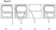
- Fig. 3 illustrates alternative embodiments of the channels. In Fig.
- FIG. 3(a) there is a single communication channel 25 disposed at one end of the reservoir well, so that any liquid transfer that does occur between wells occurs away from the drops which may be disposed near the center of the adjacent well.
- the communication channels can be jogged or redirected around barriers ( Fig. 3(d) ) to, for example, inhibit ballistic motion of fluid during impulsive accelerations.
- the average flow velocity is then ⁇ 4 cm/s and the flow rate is ⁇ 0.7 ⁇ l/s.
- the acceleration is transient (e.g., due to a bump)
- the total flow can be small even if a is large.
- the viscosity of air 1.78 ⁇ 10 -5 Pa s, is 50 times smaller than that of water, so flow rates for a given pressure difference are much larger.
- a second and, for reducing liquid transfer between wells, more important effect is the pinning of liquid contact lines by solid surfaces.
- the contact angle ⁇ formed by the air-liquid interface at a solid surface is determined by the properties of the liquid and surface. In a channel or tube, this leads to the formation of a curved liquid meniscus.
- ⁇ p 2 ⁇ cos( ⁇ ) / r, where ⁇ is the liquid surface tension and r is the radius of the channel or tube.
- the liquid contact line and the meniscus will remain pinned for some range of values ⁇ between ⁇ min and ⁇ max ; the difference between these extreme angles is the contact angle hysteresis, and is determined by the wall roughness, among other factors.
- ⁇ p min 1500 Pa.
- the pressure difference required to produce flow will be larger than the hydrostatic pressure difference generated when the microplate is tilted or inverted.
- the pressure difference required to produce flow will be larger than the hydrostatic pressure difference generated when the microplate is tilted or inverted.
- it will be roughly 30 times larger, suggesting that microplate accelerations up to ⁇ 30 g will not cause fluid motion.
- any liquid volume that is transferred between wells tends to be extremely small. This transfer can be inhibited to some extent by placing a small barrier or "splash guard" in front of the entrance and exit of the communication channels; and by extending the length of the channel by curving, bending or jogging it. Excess pressure developed during accelerations must first drive flow through the entire length of the channel. If the communication channel width is small enough and the path long enough, the liquid will not reach the other well during the duration of the acceleration and associated excess pressure. However, repeated large accelerations may eventually drive very small amounts of fluid out of the communication channel and into the adjacent well.
- appropriately arranged communication channels can also minimize the effects of small liquid transfers, especially those occurring due to rough handling and impulsive forces.
- the channels can be arranged so that any liquid that flows into them from the reservoir well and then out of them to the protein/adjacent well is unlikely to contact the protein drops on the bottom of the well. This can be accomplished by directing the communication channel outlets away from the drops.
- the channels can be disposed at either end and directed away from the protein drops. Guards placed at the outlet of the channel can be used to deflect liquid down the sides of the well wall.
- Vapor communication channels can also provide some control over the rate of vapor transfer and vapor equilibration between connected wells.
- the rate of transfer of volatile components of the liquids in the wells - including water and alcohols - depends upon the rate of evaporation per unit area from the liquid-air interface, the surface area of liquid-air interface, and the rate of vapor diffusion and convection.
- the communication channels affect vapor diffusion, by constricting the area through which diffusion occurs, and vapor convection, since convection within the channels is strongly suppressed in sufficiently small channels, e.g., those of the prototypes described above.
- the modulation of the net rate of transfer of volatile components between wells is determined by which process - evaporation from the liquid surface, convective and diffusive transport within each well, or diffusive transport through the channel - is slowest.
- the effects of the channels may be dominant, but for slowly evaporating solutions like aqueous buffer containing 30% polyethylene glycol, the evaporation rate may be limiting.
- reducing the channel cross-section dimensions and increasing their length should eventually make transport through the channel the limiting step.
- the channel dimensions and the total number of channels can then be used to control - specifically, to reduce relative to the large-area channel limit - the rate of vapor transport and equilibration between wells.
- the liquid retention ledge/aperture is formed by a ledge 55 that projects outward from the walls 45 of the well, at some position between the bottom and top of the well.
- the parameters of this ledge are its thickness, the ratio of this thickness to the well depth, the dimensions of its inner aperture 60 (or the amount by which the ledge projects outward from the well wall) and its height above the bottom of the well.
- the ledge can be tilted upward or downward. It may have a rectangular cross-section ( Fig. 4(a) and (b) ). It may instead have a bottom surface that, e.g., curves to meet with the wall ( Fig. 4(c) and (d) ).
- the well bottoms may be open - to be sealed by a separate part - as in Fig. 4(b) and (d) ; or one or all wells within a cell may have an enclosed bottom, as in Fig. 4 (e-g).
- the wells within a cell may have the same depth ( Fig. 4(b) and (d) ), or they may have different depths ( Fig. 4(e-g) ).
- the plastics used in conventional injection molded microplates tend to be somewhat hydrophobic. As illustrated in Fig. 5(a) , when aqueous solutions are dispensed into conventional flat or curved bottom wells, they tend to form hemispherical domes 90 on the bottom of the well 75 rather than wet and spread uniformly throughout the well.
- the liquid may reside only near the center of the typically rectangular or elongated wells, or it may be drawn to a corner. Consequently, for fixed volume the exposed surface area of the liquid will vary, changing the rate of equilibration of the liquids in each well. This also makes it more difficult to completely fill a well without it overflowing, or without having liquid touch the top sealing film 85 when the plate is sealed.
- Figure 6(a) shows a sequence of images acquired during filling of the reservoir well of a commercial protein crystallization microplate.
- the liquid often accumulates in one side of the well, and the liquid level rises to the top of the well on that side, before the liquid finally spreads across the entire bottom of the well.
- Fully filling the well is usually impossible without having liquid contact the top sealing surface, which can prevent plate sealing.
- the sealing film is not applied, when the plate is tilted to 90 degrees or inverted, most or all of the liquid will flow out of the well. With the top sealing film applied, tilting or inversion will typically result in substantial liquid transfer between wells.
- the minimum outward projection of the ledges from the well wall required to keep liquid from rising to the top surface of the plate (and contacting the sealing film) depends on the shape of the liquid drop formed on the bottom of the well during filling, on the ratio of the well depth to well width, on the vertical position of the ledge relative to the bottom of the well, and also on how the plate is filled.
- the drop shape depends on its volume, surface tension and contact angle at the well bottom. For a small depth to width ratio and/or for a ledge placement near the top of the well as in Fig. 5(b) , the ledge must be relatively wide, whereas for a large depth to width ratio or for ledge placement closer to the bottom of the well, the ledge can be relatively small.
- the ledge width can be reduced at the narrower ends of the wells relative to on the wider sides of the wells, as the ledges on the wider sides will largely determine liquid retention. If the liquid is not dispensed in the center of the well but is dispensed toward one side, the ledge projection can be reduced and still effectively contain the liquid.
- FIG. 6(a) shows a sequence of images as liquid is added to a conventional well on a commercial 96 cell plate. The liquid spreads and then rises to the top surface of the plate at the left end of the plate (so that it will contact the sealing film when the plate is sealed) before continuing to spread to the right end. When the plate is tilted, the liquid freely flows out of the well.
- Figure 6(b) shows a corresponding sequence of images in a prototype plate according to the present invention.
- the liquid quickly contacts the bottom surface of the ledge, and then spreads uniformly beneath the ledge until the entire volume below the ledge (with the possible exception of a small bubble) is filled.
- the plate can be tilted to any orientation or inverted without liquid flow out of the well through the aperture.
- experiments with ledges of varying widths / extensions from the well sidewall suggest that the utility of the ledges in promoting liquid spreading and more uniform well filling is largely insensitive to ledge width, for widths of at least 0.2 mm.
- the liquid retention ledge/aperture inhibits liquid flow out though the aperture by several mechanisms.
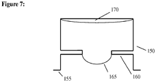
- This pressure (roughly 150 Pa for water in a 1 mm radius aperture), can exceed the hydrostatic pressure in the liquid in a shallow well, and prevent it from moving.
- the top sealing surface 155 of the microplate must be far enough away so that liquid bulging through the aperture does not contact the sealing film sealing this top surface when, e.g., the plate is inverted after filling.
- the liquid is incompressible.
- the gas volume in the unfilled space 170 on the "filled" side of the aperture must increase, producing a decrease in pressure in that space that opposes the motion. If the initial gas volume is very small, the pressure drop for even small displacements may be large. For example, if the unfilled volume below the aperture in a 40 microliter well is 4 microliters (10%), the formation of a 1 millimeter diameter hemispherical liquid bulge through the aperture produces a pressure drop of 6500 Pa, or roughly 130 times larger than hydrostatic pressure.
- the well can be made more nearly square or circular, as viewed from above.
- the corners 70 of the well can be rounded ( Fig. 4(c) and (d) ) to reduce trapping of air bubbles there, especially below the bottom surface of the ledge.
- Wider ledges tend to trap air beneath the ledge at either end of a rectangular well. This trapping can be reduced by reducing the width of the ledge. For rectangular or otherwise elongated wells, the width can be reduced only at the well ends ( Fig. 8(b) ), minimizing air trapping while minimizing the width of the aperture. Small diameter (e.g., 150 micrometer) "vent" apertures can be disposed in the ledge at either end of the well, allowing air to escape through them during filling from the center. The ledge can be then be extended to form a continuous sheet across the well, with holes for filling and venting ( Fig. 8(c) ).
- the filling aperture can be disposed at one end of the well and a single vent aperture at the other end ( Fig. 8(d) ).
- the filling aperture can be disposed in the middle, and thin slits extended from either side of it as in Fig. 8(e) to allow gas escape during filling but to minimize fluid motion out compared with, e.g., the apertures in Fig. 8(a) and (b) during handling and acceleration.
- any liquid motion and especially the bubble formation described above occur on a timescale that is determined by the liquid's viscosity. This viscosity thus inhibits bubble formation and liquid flow out of the aperture in response to impulsive and other short-duration perturbations.
- microplates between laboratories it is desirable to be able to ship microplates between laboratories by conventional mail or courier service.
- This shipping requires that (1) variations in average temperature be minimized to prevent freezing, precipitation and other effects that may damage the samples in the plate; (2) temperature gradients across the plate be minimized to prevent evaporation and condensation; and (3) peak accelerations be minimized to minimize liquid transfer between wells.
- (1) and (2) can be achieved using standard commercial shipping containers, such as those comprised of insulating Styrofoam boxes with high heat capacity gel packs inside to maintain temperature.
- a commercial microplate system for, e.g., protein crystallization, shipping and X-ray inspection may then comprise a microplate with liquid retention ledges/apertures and narrow vapor communication channels; a cardboard box lined with shock-absorbing foam; an interior thermally insulating Styrofoam container; high heat capacity gel packs; and additional foam or bubble packaging to further reduce accelerations of plates inside the Styrofoam container.
- microplates may also experience reduced ambient pressures.
- the plate bottom is sealed, either during injection molding or by attachment of a separate film or plate or injection molded part.
- Reservoir liquid is dispensed using a manual pipetter or automated liquid handler through the liquid retaining aperture and into the well below, filling the well below the liquid retention ledge as completely as possible Protein solution is then dispensed as drops on the bottom surface of the adjacent protein well.
- the top surface of the microplate is then sealed using a vapor-impermeable sealing film.
- the plate is then rotated to a desired orientation (usually either its original horizontal orientation or an inverted orientation) for crystal growth.
- the plate is then rotated to another orientation (usually vertical) to examine the contents of each cell using X-rays, UV or visible light, or other probes.
- the plate may also be rotated to a vertical orientation immediately after filling, allowing vertical storage and inspection during the experiment. This may be preferable to storage in a horizontal orientation if a plate to be inspected in a vertical orientation multiple times during an experiment.
Landscapes
- Chemical & Material Sciences (AREA)
- Health & Medical Sciences (AREA)
- Organic Chemistry (AREA)
- Engineering & Computer Science (AREA)
- Life Sciences & Earth Sciences (AREA)
- General Health & Medical Sciences (AREA)
- Wood Science & Technology (AREA)
- Bioinformatics & Cheminformatics (AREA)
- Zoology (AREA)
- Clinical Laboratory Science (AREA)
- Biochemistry (AREA)
- Genetics & Genomics (AREA)
- Crystallography & Structural Chemistry (AREA)
- Analytical Chemistry (AREA)
- Microbiology (AREA)
- Biomedical Technology (AREA)
- Sustainable Development (AREA)
- Biotechnology (AREA)
- General Engineering & Computer Science (AREA)
- Hematology (AREA)
- Metallurgy (AREA)
- Materials Engineering (AREA)
- Chemical Kinetics & Catalysis (AREA)
- Biophysics (AREA)
- Medicinal Chemistry (AREA)
- Molecular Biology (AREA)
- Proteomics, Peptides & Aminoacids (AREA)
- Sampling And Sample Adjustment (AREA)
- Apparatus Associated With Microorganisms And Enzymes (AREA)
Claims (14)
- Microplaque, comprenant :
un cadre présentant une surface supérieure sensiblement plane, une surface inférieure, et à l'intérieur duquel est contenue une pluralité de cellules, chaque cellule comprenant :un premier puits ;un deuxième puits ;où le premier puits et le deuxième puits sont séparés par une paroi de séparation s'étendant dans une première direction de la surface inférieure à la surface supérieure du cadre, et s'étendant dans une deuxième direction le long d'un axe longitudinal ; etoù le premier puits et le deuxième puits sont reliés par au moins un canal de communication de vapeur (17, 25, 30, 35, 40) ayant une dimension, une forme et un emplacement permettant une communication de vapeur entre le premier puits et le deuxième puits, et facilitant le blocage de transfert de liquide entre le premier puits et le deuxième puits si au moins une cellule contient un liquide et si le cadre est incliné à partir d'une position horizontale ou si le cadre est soumis à des accélérations subites,où ledit au moins un canal de communication de vapeur (17, 25, 30, 35, 40) est gravé dans la surface supérieure du cadre,où une surface supérieure de la paroi de séparation comprend un point central et deux points d'extrémité, eta) où ledit au moins un canal de communication de vapeur (40) est décalé ou redirigé autour de barrières ; et/oub) où ledit au moins un canal de communication de vapeur (30, 35) est positionné à un emplacement entre le point central et un des deux points d'extrémité de la surface supérieure de la paroi de séparation ; et/ouc) où ledit au moins un canal de communication de vapeur (35) forme un angle avec l'axe longitudinal. - Microplaque selon la revendication 1, où ledit au moins un canal de communication de vapeur (17, 25, 30, 35, 40) est adjacent à un des deux points d'extrémité de la surface supérieure de la paroi de séparation.
- Microplaque selon la revendication 1 ou la revendication 2, où ledit au moins un canal de communication de vapeur (40) est non linéaire.
- Microplaque selon la revendication 1, comprenant en outre un rebord de retenue de liquide (16, 55, 65) raccordé à au moins une partie d'un périmètre intérieur d'un puits entre le premier puits et le deuxième puits et s'étendant autour de celle-ci, à une distance définie en dessous de la surface supérieure du cadre, et en saillie vers l'extérieur depuis le périmètre intérieur en forment une ouverture ayant un diamètre inférieur au diamètre de l'intérieur du puits entre le premier puits et le deuxième puits.
- Microplaque selon la revendication 4, où le rebord de retenue de liquide (16, 55, 65) est structuré de manière à faciliter un remplissage uniforme du puits entre le premier puits et le deuxième puits par un liquide quand ledit liquide est ajouté, et pour faciliter l'inhibition de la formation de bulles d'air intérieures,
où le rebord de retenue de liquide (16, 55, 65) est préférentiellement structuré pour coller à la ligne de contact du liquide quand ledit liquide est ajouté au puits entre le premier puits et le deuxième puits, en facilitant ainsi l'inhibition d'un dépassement par le liquide du niveau du rebord de retenue de liquide (16, 55, 65) pendant l'ajout du liquide, et
où le rebord de retenue de liquide fait en outre préférentiellement saillie vers l'extérieur à une distance d'au moins 0,2 millimètres du périmètre intérieur du puits entre le premier puits et le deuxième puits. - Microplaque selon la revendication 4, où le rebord de retenue de liquide (16, 55, 65) est structuré de manière à faciliter l'inhibition d'une fuite de liquide hors du puits entre le premier puits et le deuxième puits quand le cadre est incliné à partir d'une position horizontale ou quand le cadre est soumis à des accélérations subites, et
où le rebord de retenue de liquide (16, 55, 65) a préférentiellement une section transversale rectangulaire. - Microplaque selon la revendication 6, où le rebord de retenue de liquide (16, 55, 65) comprend une partie de fond courbe, ladite partie de fond courbe du rebord de retenue de liquide (16, 55, 65) étant structurée de manière à faciliter l'inhibition du piégeage de bulles d'air pendant le remplissage par le liquide du puits entre le premier puits et le deuxième puits.
- Microplaque selon la revendication 7, où le rebord de retenue de liquide (16, 55, 65) est structuré de manière à former une pluralité d'ouvertures.
- Microplaque selon la revendication 8, où une première ouverture de la pluralité d'ouvertures est adjacente au périmètre intérieur du puits entre le premier puits et le deuxième puits.
- Microplaque selon la revendication 9, où une deuxième ouverture de la pluralité d'ouvertures est formée sensiblement centralement dans le puits entre le premier puits et le deuxième puits.
- Microplaque selon la revendication 10, où chaque ouverture entre la première et la deuxième ouverture de la pluralité d'ouvertures a une forme sensiblement circulaire.
- Microplaque selon la revendication 11, où le diamètre de la deuxième ouverture de la pluralité d'ouvertures est supérieur au diamètre de la première ouverture de la pluralité d'ouvertures.
- Microplaque selon la revendication 4, où le puits entre le premier puits et le deuxième puits présentant le rebord de retenue de liquide (65) comprend en outre une partie inférieure à coins arrondis.
- Microplaque selon l'une des revendications 1 à 13, où ledit au moins un canal de communication de vapeur (17, 25, 30, 35, 40) a une largeur comprise entre 0,075 millimètres et 0,25 millimètres.
Applications Claiming Priority (2)
| Application Number | Priority Date | Filing Date | Title |
|---|---|---|---|
| US201261617102P | 2012-03-29 | 2012-03-29 | |
| PCT/US2013/034251 WO2013148938A1 (fr) | 2012-03-29 | 2013-03-28 | Améliorations de microplaques et procédés de cristallisation et de biotechnologie protéiques |
Publications (3)
| Publication Number | Publication Date |
|---|---|
| EP2831220A1 EP2831220A1 (fr) | 2015-02-04 |
| EP2831220A4 EP2831220A4 (fr) | 2016-01-27 |
| EP2831220B1 true EP2831220B1 (fr) | 2020-10-21 |
Family
ID=49261231
Family Applications (1)
| Application Number | Title | Priority Date | Filing Date |
|---|---|---|---|
| EP13769204.2A Active EP2831220B1 (fr) | 2012-03-29 | 2013-03-28 | Améliorations de microplaques |
Country Status (4)
| Country | Link |
|---|---|
| US (1) | US9855557B2 (fr) |
| EP (1) | EP2831220B1 (fr) |
| CN (1) | CN104204187B (fr) |
| WO (1) | WO2013148938A1 (fr) |
Families Citing this family (25)
| Publication number | Priority date | Publication date | Assignee | Title |
|---|---|---|---|---|
| CN103998394B (zh) | 2011-08-01 | 2016-08-17 | 德诺弗科学公司 | 细胞捕获系统和使用方法 |
| US10466160B2 (en) | 2011-08-01 | 2019-11-05 | Celsee Diagnostics, Inc. | System and method for retrieving and analyzing particles |
| US9404864B2 (en) | 2013-03-13 | 2016-08-02 | Denovo Sciences, Inc. | System for imaging captured cells |
| EP2698624A1 (fr) * | 2012-08-16 | 2014-02-19 | Siemens Healthcare Diagnostics Products GmbH | Récipient réactionnel |
| US9752181B2 (en) | 2013-01-26 | 2017-09-05 | Denovo Sciences, Inc. | System and method for capturing and analyzing cells |
| US9707562B2 (en) | 2013-03-13 | 2017-07-18 | Denovo Sciences, Inc. | System for capturing and analyzing cells |
| US9856535B2 (en) * | 2013-05-31 | 2018-01-02 | Denovo Sciences, Inc. | System for isolating cells |
| US10391490B2 (en) | 2013-05-31 | 2019-08-27 | Celsee Diagnostics, Inc. | System and method for isolating and analyzing cells |
| WO2015051678A1 (fr) * | 2013-10-09 | 2015-04-16 | 上海交通大学 | Plaque microporeuse de détection à haut débit et son application |
| CN104569377B (zh) * | 2013-10-09 | 2018-12-25 | 上海交通大学 | 一种用于高通量检测的微孔板及其应用 |
| WO2016112239A1 (fr) * | 2015-01-08 | 2016-07-14 | Brookhaven Science Associates, Llc | Plaque flexible dotée d'insertions amovibles et couvercle |
| WO2018009870A1 (fr) | 2016-07-07 | 2018-01-11 | David Beebe | Plaque plaque de microtitration et utilisations associées |
| WO2018180357A1 (fr) * | 2017-03-31 | 2018-10-04 | 株式会社エンプラス | Appareil de manipulation de liquide |
| AU2018323449B2 (en) | 2017-08-29 | 2020-09-03 | Bio-Rad Laboratories, Inc. | System and method for isolating and analyzing cells |
| WO2019136376A1 (fr) | 2018-01-08 | 2019-07-11 | Illumina, Inc. | Séquençage à haut débit à détection à semi-conducteur |
| KR102588004B1 (ko) * | 2018-01-08 | 2023-10-11 | 일루미나, 인코포레이티드 | 반도체-기반 검출을 사용한 고-처리율 서열분석 |
| WO2019226738A1 (fr) * | 2018-05-22 | 2019-11-28 | Mitegen, Llc | Système de refroidissement et de réchauffement rapides de cellules et d'autres matériaux biologiques |
| EP3935372A4 (fr) | 2019-03-06 | 2022-11-09 | Mitegen, LLC | Système de maintien d'échantillon de cristallographie synchrotron en série |
| US10633693B1 (en) | 2019-04-16 | 2020-04-28 | Celsee Diagnostics, Inc. | System and method for leakage control in a particle capture system |
| CN114072490A (zh) | 2019-05-07 | 2022-02-18 | 伯乐实验室有限公司 | 用于自动化的单细胞加工的系统和方法 |
| US11273439B2 (en) | 2019-05-07 | 2022-03-15 | Bio-Rad Laboratories, Inc. | System and method for target material retrieval from microwells |
| SG11202112898WA (en) | 2019-06-14 | 2021-12-30 | Bio Rad Laboratories | System and method for automated single cell processing and analyses |
| CN110256527B (zh) * | 2019-07-23 | 2020-07-28 | 中国科学院生物物理研究所 | 一种用于原位x-射线衍射的蛋白质复合育晶盒 |
| US11504719B2 (en) | 2020-03-12 | 2022-11-22 | Bio-Rad Laboratories, Inc. | System and method for receiving and delivering a fluid for sample processing |
| CN117160547B (zh) * | 2023-10-25 | 2024-01-02 | 南京浦蓝大气环境研究院有限公司 | 一种可适应多种环境的大气环境模拟装置 |
Family Cites Families (8)
| Publication number | Priority date | Publication date | Assignee | Title |
|---|---|---|---|---|
| US6913732B2 (en) * | 2001-03-19 | 2005-07-05 | Corning Incorporated | Microplate for performing crystallography studies and methods for making and using such microplates |
| AU2002320507A1 (en) * | 2001-07-13 | 2003-01-29 | Caliper Technologies Corp. | Microfluidic devices and systems for separating components of a mixture |
| WO2003031952A1 (fr) * | 2001-09-28 | 2003-04-17 | Hitachi, Ltd. | Dispositif de detection de luminescence et plaque de jeux ordonnes de microechantillons |
| CA2473390C (fr) * | 2002-01-18 | 2009-11-24 | Neuro Probe Incorporated | Appareil de formation de cristaux et son procede d'utilisation |
| EP1699538B1 (fr) * | 2003-01-17 | 2008-01-30 | Nextal Biotechnologie Inc. | Plateaux de cristallisation preremplis et leurs procedes de realisation et d'utilisation |
| WO2007076023A2 (fr) * | 2005-12-21 | 2007-07-05 | Meso Scale Technologies, Llc | Modules d’essais a reactifs d’essais et leurs procedes de preparation et d’emploi |
| EP2222402A1 (fr) * | 2007-10-31 | 2010-09-01 | Janssen Pharmaceutica, N.V. | Dispositif et procédé de criblage à haut débit de conditions de cristallisation dans un environnement de diffusion de vapeur |
| US8641267B2 (en) * | 2008-04-14 | 2014-02-04 | Agilent Technologies, Inc. | Fluidic conduit with repeated disturbance of laminar flow |
-
2013
- 2013-03-28 CN CN201380017645.XA patent/CN104204187B/zh active Active
- 2013-03-28 WO PCT/US2013/034251 patent/WO2013148938A1/fr active Application Filing
- 2013-03-28 US US14/385,573 patent/US9855557B2/en active Active
- 2013-03-28 EP EP13769204.2A patent/EP2831220B1/fr active Active
Non-Patent Citations (1)
| Title |
|---|
| None * |
Also Published As
| Publication number | Publication date |
|---|---|
| WO2013148938A1 (fr) | 2013-10-03 |
| CN104204187A (zh) | 2014-12-10 |
| EP2831220A1 (fr) | 2015-02-04 |
| CN104204187B (zh) | 2017-06-13 |
| EP2831220A4 (fr) | 2016-01-27 |
| US20150093306A1 (en) | 2015-04-02 |
| US9855557B2 (en) | 2018-01-02 |
Similar Documents
| Publication | Publication Date | Title |
|---|---|---|
| EP2831220B1 (fr) | Améliorations de microplaques | |
| JP6739351B2 (ja) | 生物試料分析用の単一列マイクロプレートシステム及び搬送体 | |
| US5554536A (en) | Biological analysis device having improved contamination prevention | |
| US7232549B2 (en) | Apparatus for controlling the free surface of a liquid in a well plate | |
| US7244392B1 (en) | Slide-in cassette for a cup for testing of drugs of abuse | |
| US20130029412A1 (en) | Cell culture system | |
| US20170135336A1 (en) | Capillary assisted vitrification processes and devices | |
| WO1993024232A1 (fr) | Pipette a pointe cone etalonnee et son procede d'utilisation | |
| JP4680037B2 (ja) | 流体取扱装置およびそれに用いる流体取扱ユニット | |
| CN108603759B (zh) | 用于水平仪的具有改善的可见性的瓶 | |
| WO2005036138A1 (fr) | Systeme, kit et procede de mesure de la diffusion membranaire | |
| ES2370165T3 (es) | Bandeja con protuberancias. | |
| US9333503B2 (en) | Sample chamber with parting plate | |
| JP2019113472A (ja) | 秤取構造及びマイクロチップ | |
| JP5043822B2 (ja) | クロージャにリザーバを有する流体容器および使用法 | |
| US20220395833A1 (en) | Microfluidic cell culture system | |
| CN100448503C (zh) | 预填充的结晶板及其制备和应用方法 | |
| CN118201712A (zh) | 孔板设备及其填充方法 | |
| JP2021185891A (ja) | マイクロ流体デバイス | |
| CN110621770B (zh) | Pcr用容器、装试剂的pcr用容器及试剂盒 | |
| WO1990015333A1 (fr) | Appareil et procede d'auto-nivelage d'un liquide dans un recipient | |
| GB2396835A (en) | External meniscus fluid bubble, leak prevention vial |
Legal Events
| Date | Code | Title | Description |
|---|---|---|---|
| PUAI | Public reference made under article 153(3) epc to a published international application that has entered the european phase |
Free format text: ORIGINAL CODE: 0009012 |
|
| 17P | Request for examination filed |
Effective date: 20141028 |
|
| AK | Designated contracting states |
Kind code of ref document: A1 Designated state(s): AL AT BE BG CH CY CZ DE DK EE ES FI FR GB GR HR HU IE IS IT LI LT LU LV MC MK MT NL NO PL PT RO RS SE SI SK SM TR |
|
| AX | Request for extension of the european patent |
Extension state: BA ME |
|
| DAX | Request for extension of the european patent (deleted) | ||
| RA4 | Supplementary search report drawn up and despatched (corrected) |
Effective date: 20160105 |
|
| RIC1 | Information provided on ipc code assigned before grant |
Ipc: C12M 1/18 20060101AFI20151221BHEP |
|
| STAA | Information on the status of an ep patent application or granted ep patent |
Free format text: STATUS: EXAMINATION IS IN PROGRESS |
|
| 17Q | First examination report despatched |
Effective date: 20191106 |
|
| GRAP | Despatch of communication of intention to grant a patent |
Free format text: ORIGINAL CODE: EPIDOSNIGR1 |
|
| STAA | Information on the status of an ep patent application or granted ep patent |
Free format text: STATUS: GRANT OF PATENT IS INTENDED |
|
| INTG | Intention to grant announced |
Effective date: 20200520 |
|
| GRAS | Grant fee paid |
Free format text: ORIGINAL CODE: EPIDOSNIGR3 |
|
| GRAA | (expected) grant |
Free format text: ORIGINAL CODE: 0009210 |
|
| STAA | Information on the status of an ep patent application or granted ep patent |
Free format text: STATUS: THE PATENT HAS BEEN GRANTED |
|
| AK | Designated contracting states |
Kind code of ref document: B1 Designated state(s): AL AT BE BG CH CY CZ DE DK EE ES FI FR GB GR HR HU IE IS IT LI LT LU LV MC MK MT NL NO PL PT RO RS SE SI SK SM TR |
|
| REG | Reference to a national code |
Ref country code: GB Ref legal event code: FG4D |
|
| REG | Reference to a national code |
Ref country code: CH Ref legal event code: EP |
|
| REG | Reference to a national code |
Ref country code: DE Ref legal event code: R096 Ref document number: 602013073462 Country of ref document: DE |
|
| REG | Reference to a national code |
Ref country code: IE Ref legal event code: FG4D |
|
| REG | Reference to a national code |
Ref country code: AT Ref legal event code: REF Ref document number: 1325905 Country of ref document: AT Kind code of ref document: T Effective date: 20201115 |
|
| REG | Reference to a national code |
Ref country code: AT Ref legal event code: MK05 Ref document number: 1325905 Country of ref document: AT Kind code of ref document: T Effective date: 20201021 |
|
| REG | Reference to a national code |
Ref country code: NL Ref legal event code: MP Effective date: 20201021 |
|
| PG25 | Lapsed in a contracting state [announced via postgrant information from national office to epo] |
Ref country code: FI Free format text: LAPSE BECAUSE OF FAILURE TO SUBMIT A TRANSLATION OF THE DESCRIPTION OR TO PAY THE FEE WITHIN THE PRESCRIBED TIME-LIMIT Effective date: 20201021 Ref country code: RS Free format text: LAPSE BECAUSE OF FAILURE TO SUBMIT A TRANSLATION OF THE DESCRIPTION OR TO PAY THE FEE WITHIN THE PRESCRIBED TIME-LIMIT Effective date: 20201021 Ref country code: PT Free format text: LAPSE BECAUSE OF FAILURE TO SUBMIT A TRANSLATION OF THE DESCRIPTION OR TO PAY THE FEE WITHIN THE PRESCRIBED TIME-LIMIT Effective date: 20210222 Ref country code: NO Free format text: LAPSE BECAUSE OF FAILURE TO SUBMIT A TRANSLATION OF THE DESCRIPTION OR TO PAY THE FEE WITHIN THE PRESCRIBED TIME-LIMIT Effective date: 20210121 Ref country code: NL Free format text: LAPSE BECAUSE OF FAILURE TO SUBMIT A TRANSLATION OF THE DESCRIPTION OR TO PAY THE FEE WITHIN THE PRESCRIBED TIME-LIMIT Effective date: 20201021 Ref country code: GR Free format text: LAPSE BECAUSE OF FAILURE TO SUBMIT A TRANSLATION OF THE DESCRIPTION OR TO PAY THE FEE WITHIN THE PRESCRIBED TIME-LIMIT Effective date: 20210122 |
|
| REG | Reference to a national code |
Ref country code: LT Ref legal event code: MG4D |
|
| PG25 | Lapsed in a contracting state [announced via postgrant information from national office to epo] |
Ref country code: ES Free format text: LAPSE BECAUSE OF FAILURE TO SUBMIT A TRANSLATION OF THE DESCRIPTION OR TO PAY THE FEE WITHIN THE PRESCRIBED TIME-LIMIT Effective date: 20201021 Ref country code: AT Free format text: LAPSE BECAUSE OF FAILURE TO SUBMIT A TRANSLATION OF THE DESCRIPTION OR TO PAY THE FEE WITHIN THE PRESCRIBED TIME-LIMIT Effective date: 20201021 Ref country code: BG Free format text: LAPSE BECAUSE OF FAILURE TO SUBMIT A TRANSLATION OF THE DESCRIPTION OR TO PAY THE FEE WITHIN THE PRESCRIBED TIME-LIMIT Effective date: 20210121 Ref country code: SE Free format text: LAPSE BECAUSE OF FAILURE TO SUBMIT A TRANSLATION OF THE DESCRIPTION OR TO PAY THE FEE WITHIN THE PRESCRIBED TIME-LIMIT Effective date: 20201021 Ref country code: PL Free format text: LAPSE BECAUSE OF FAILURE TO SUBMIT A TRANSLATION OF THE DESCRIPTION OR TO PAY THE FEE WITHIN THE PRESCRIBED TIME-LIMIT Effective date: 20201021 Ref country code: IS Free format text: LAPSE BECAUSE OF FAILURE TO SUBMIT A TRANSLATION OF THE DESCRIPTION OR TO PAY THE FEE WITHIN THE PRESCRIBED TIME-LIMIT Effective date: 20210221 Ref country code: LV Free format text: LAPSE BECAUSE OF FAILURE TO SUBMIT A TRANSLATION OF THE DESCRIPTION OR TO PAY THE FEE WITHIN THE PRESCRIBED TIME-LIMIT Effective date: 20201021 |
|
| PG25 | Lapsed in a contracting state [announced via postgrant information from national office to epo] |
Ref country code: HR Free format text: LAPSE BECAUSE OF FAILURE TO SUBMIT A TRANSLATION OF THE DESCRIPTION OR TO PAY THE FEE WITHIN THE PRESCRIBED TIME-LIMIT Effective date: 20201021 |
|
| REG | Reference to a national code |
Ref country code: DE Ref legal event code: R097 Ref document number: 602013073462 Country of ref document: DE |
|
| PG25 | Lapsed in a contracting state [announced via postgrant information from national office to epo] |
Ref country code: SK Free format text: LAPSE BECAUSE OF FAILURE TO SUBMIT A TRANSLATION OF THE DESCRIPTION OR TO PAY THE FEE WITHIN THE PRESCRIBED TIME-LIMIT Effective date: 20201021 Ref country code: RO Free format text: LAPSE BECAUSE OF FAILURE TO SUBMIT A TRANSLATION OF THE DESCRIPTION OR TO PAY THE FEE WITHIN THE PRESCRIBED TIME-LIMIT Effective date: 20201021 Ref country code: LT Free format text: LAPSE BECAUSE OF FAILURE TO SUBMIT A TRANSLATION OF THE DESCRIPTION OR TO PAY THE FEE WITHIN THE PRESCRIBED TIME-LIMIT Effective date: 20201021 Ref country code: SM Free format text: LAPSE BECAUSE OF FAILURE TO SUBMIT A TRANSLATION OF THE DESCRIPTION OR TO PAY THE FEE WITHIN THE PRESCRIBED TIME-LIMIT Effective date: 20201021 Ref country code: EE Free format text: LAPSE BECAUSE OF FAILURE TO SUBMIT A TRANSLATION OF THE DESCRIPTION OR TO PAY THE FEE WITHIN THE PRESCRIBED TIME-LIMIT Effective date: 20201021 Ref country code: CZ Free format text: LAPSE BECAUSE OF FAILURE TO SUBMIT A TRANSLATION OF THE DESCRIPTION OR TO PAY THE FEE WITHIN THE PRESCRIBED TIME-LIMIT Effective date: 20201021 |
|
| PLBE | No opposition filed within time limit |
Free format text: ORIGINAL CODE: 0009261 |
|
| STAA | Information on the status of an ep patent application or granted ep patent |
Free format text: STATUS: NO OPPOSITION FILED WITHIN TIME LIMIT |
|
| PG25 | Lapsed in a contracting state [announced via postgrant information from national office to epo] |
Ref country code: DK Free format text: LAPSE BECAUSE OF FAILURE TO SUBMIT A TRANSLATION OF THE DESCRIPTION OR TO PAY THE FEE WITHIN THE PRESCRIBED TIME-LIMIT Effective date: 20201021 |
|
| 26N | No opposition filed |
Effective date: 20210722 |
|
| PG25 | Lapsed in a contracting state [announced via postgrant information from national office to epo] |
Ref country code: IT Free format text: LAPSE BECAUSE OF FAILURE TO SUBMIT A TRANSLATION OF THE DESCRIPTION OR TO PAY THE FEE WITHIN THE PRESCRIBED TIME-LIMIT Effective date: 20201021 Ref country code: MC Free format text: LAPSE BECAUSE OF FAILURE TO SUBMIT A TRANSLATION OF THE DESCRIPTION OR TO PAY THE FEE WITHIN THE PRESCRIBED TIME-LIMIT Effective date: 20201021 Ref country code: AL Free format text: LAPSE BECAUSE OF FAILURE TO SUBMIT A TRANSLATION OF THE DESCRIPTION OR TO PAY THE FEE WITHIN THE PRESCRIBED TIME-LIMIT Effective date: 20201021 |
|
| PG25 | Lapsed in a contracting state [announced via postgrant information from national office to epo] |
Ref country code: SI Free format text: LAPSE BECAUSE OF FAILURE TO SUBMIT A TRANSLATION OF THE DESCRIPTION OR TO PAY THE FEE WITHIN THE PRESCRIBED TIME-LIMIT Effective date: 20201021 |
|
| REG | Reference to a national code |
Ref country code: BE Ref legal event code: MM Effective date: 20210331 |
|
| PG25 | Lapsed in a contracting state [announced via postgrant information from national office to epo] |
Ref country code: IE Free format text: LAPSE BECAUSE OF NON-PAYMENT OF DUE FEES Effective date: 20210328 Ref country code: LU Free format text: LAPSE BECAUSE OF NON-PAYMENT OF DUE FEES Effective date: 20210328 |
|
| PG25 | Lapsed in a contracting state [announced via postgrant information from national office to epo] |
Ref country code: IS Free format text: LAPSE BECAUSE OF FAILURE TO SUBMIT A TRANSLATION OF THE DESCRIPTION OR TO PAY THE FEE WITHIN THE PRESCRIBED TIME-LIMIT Effective date: 20210221 |
|
| PG25 | Lapsed in a contracting state [announced via postgrant information from national office to epo] |
Ref country code: BE Free format text: LAPSE BECAUSE OF NON-PAYMENT OF DUE FEES Effective date: 20210331 |
|
| PG25 | Lapsed in a contracting state [announced via postgrant information from national office to epo] |
Ref country code: HU Free format text: LAPSE BECAUSE OF FAILURE TO SUBMIT A TRANSLATION OF THE DESCRIPTION OR TO PAY THE FEE WITHIN THE PRESCRIBED TIME-LIMIT; INVALID AB INITIO Effective date: 20130328 |
|
| P01 | Opt-out of the competence of the unified patent court (upc) registered |
Effective date: 20230524 |
|
| PG25 | Lapsed in a contracting state [announced via postgrant information from national office to epo] |
Ref country code: CY Free format text: LAPSE BECAUSE OF FAILURE TO SUBMIT A TRANSLATION OF THE DESCRIPTION OR TO PAY THE FEE WITHIN THE PRESCRIBED TIME-LIMIT Effective date: 20201021 |
|
| PG25 | Lapsed in a contracting state [announced via postgrant information from national office to epo] |
Ref country code: MK Free format text: LAPSE BECAUSE OF FAILURE TO SUBMIT A TRANSLATION OF THE DESCRIPTION OR TO PAY THE FEE WITHIN THE PRESCRIBED TIME-LIMIT Effective date: 20201021 |
|
| PGFP | Annual fee paid to national office [announced via postgrant information from national office to epo] |
Ref country code: DE Payment date: 20240325 Year of fee payment: 12 Ref country code: GB Payment date: 20240328 Year of fee payment: 12 |
|
| PGFP | Annual fee paid to national office [announced via postgrant information from national office to epo] |
Ref country code: FR Payment date: 20240307 Year of fee payment: 12 |
|
| PG25 | Lapsed in a contracting state [announced via postgrant information from national office to epo] |
Ref country code: TR Free format text: LAPSE BECAUSE OF FAILURE TO SUBMIT A TRANSLATION OF THE DESCRIPTION OR TO PAY THE FEE WITHIN THE PRESCRIBED TIME-LIMIT Effective date: 20201021 |
|
| PGFP | Annual fee paid to national office [announced via postgrant information from national office to epo] |
Ref country code: CH Payment date: 20240401 Year of fee payment: 12 |
|
| PG25 | Lapsed in a contracting state [announced via postgrant information from national office to epo] |
Ref country code: MT Free format text: LAPSE BECAUSE OF FAILURE TO SUBMIT A TRANSLATION OF THE DESCRIPTION OR TO PAY THE FEE WITHIN THE PRESCRIBED TIME-LIMIT Effective date: 20201021 |