EP2830957B1 - Slide device, transport and packaging assembly - Google Patents
Slide device, transport and packaging assembly Download PDFInfo
- Publication number
- EP2830957B1 EP2830957B1 EP13704604.1A EP13704604A EP2830957B1 EP 2830957 B1 EP2830957 B1 EP 2830957B1 EP 13704604 A EP13704604 A EP 13704604A EP 2830957 B1 EP2830957 B1 EP 2830957B1
- Authority
- EP
- European Patent Office
- Prior art keywords
- piece goods
- mobile unit
- conveying device
- track
- sliding
- Prior art date
- Legal status (The legal status is an assumption and is not a legal conclusion. Google has not performed a legal analysis and makes no representation as to the accuracy of the status listed.)
- Not-in-force
Links
Images

Classifications
-
- B—PERFORMING OPERATIONS; TRANSPORTING
- B65—CONVEYING; PACKING; STORING; HANDLING THIN OR FILAMENTARY MATERIAL
- B65B—MACHINES, APPARATUS OR DEVICES FOR, OR METHODS OF, PACKAGING ARTICLES OR MATERIALS; UNPACKING
- B65B35/00—Supplying, feeding, arranging or orientating articles to be packaged
- B65B35/10—Feeding, e.g. conveying, single articles
- B65B35/20—Feeding, e.g. conveying, single articles by reciprocating or oscillatory pushers
- B65B35/205—Feeding, e.g. conveying, single articles by reciprocating or oscillatory pushers linked to endless conveyors
-
- B—PERFORMING OPERATIONS; TRANSPORTING
- B65—CONVEYING; PACKING; STORING; HANDLING THIN OR FILAMENTARY MATERIAL
- B65B—MACHINES, APPARATUS OR DEVICES FOR, OR METHODS OF, PACKAGING ARTICLES OR MATERIALS; UNPACKING
- B65B5/00—Packaging individual articles in containers or receptacles, e.g. bags, sacks, boxes, cartons, cans, jars
- B65B5/04—Packaging single articles
-
- B—PERFORMING OPERATIONS; TRANSPORTING
- B65—CONVEYING; PACKING; STORING; HANDLING THIN OR FILAMENTARY MATERIAL
- B65B—MACHINES, APPARATUS OR DEVICES FOR, OR METHODS OF, PACKAGING ARTICLES OR MATERIALS; UNPACKING
- B65B5/00—Packaging individual articles in containers or receptacles, e.g. bags, sacks, boxes, cartons, cans, jars
- B65B5/08—Packaging groups of articles, the articles being individually gripped or guided for transfer to the containers or receptacles
-
- B—PERFORMING OPERATIONS; TRANSPORTING
- B65—CONVEYING; PACKING; STORING; HANDLING THIN OR FILAMENTARY MATERIAL
- B65G—TRANSPORT OR STORAGE DEVICES, e.g. CONVEYORS FOR LOADING OR TIPPING, SHOP CONVEYOR SYSTEMS OR PNEUMATIC TUBE CONVEYORS
- B65G37/00—Combinations of mechanical conveyors of the same kind, or of different kinds, of interest apart from their application in particular machines or use in particular manufacturing processes
-
- B—PERFORMING OPERATIONS; TRANSPORTING
- B65—CONVEYING; PACKING; STORING; HANDLING THIN OR FILAMENTARY MATERIAL
- B65G—TRANSPORT OR STORAGE DEVICES, e.g. CONVEYORS FOR LOADING OR TIPPING, SHOP CONVEYOR SYSTEMS OR PNEUMATIC TUBE CONVEYORS
- B65G47/00—Article or material-handling devices associated with conveyors; Methods employing such devices
- B65G47/74—Feeding, transfer, or discharging devices of particular kinds or types
- B65G47/76—Fixed or adjustable ploughs or transverse scrapers
- B65G47/766—Adjustable ploughs or transverse scrapers
-
- B—PERFORMING OPERATIONS; TRANSPORTING
- B65—CONVEYING; PACKING; STORING; HANDLING THIN OR FILAMENTARY MATERIAL
- B65G—TRANSPORT OR STORAGE DEVICES, e.g. CONVEYORS FOR LOADING OR TIPPING, SHOP CONVEYOR SYSTEMS OR PNEUMATIC TUBE CONVEYORS
- B65G47/00—Article or material-handling devices associated with conveyors; Methods employing such devices
- B65G47/74—Feeding, transfer, or discharging devices of particular kinds or types
- B65G47/82—Rotary or reciprocating members for direct action on articles or materials, e.g. pushers, rakes, shovels
Definitions
- the present invention relates to a sliding device for pushing piece goods from a conveyor and a transport arrangement with a conveyor for transporting piece goods and the sliding device. Furthermore, the invention relates to a packaging arrangement with the transport arrangement and a method for pushing out piece goods from a conveyor.
- the products are first taken in each case by a pair of cell angles on a transport system and supplied stepwise or continuously to the actual cartoning process.
- the sliding or leading cell angles are each connected to two roller chains and can be adjusted manually by relative displacement of the chains to the corresponding product width.
- the products are taken up by a pair of cell angles.
- conventional cartoning is provided as a carrier for the cartons and to support the Aufrichtvones a parallel to the product chain and synchronously running so-called Faltschachtelkette.
- Faltschachtelkette the following slide-in systems are used in cartoning machines for pushing the products into the opened folding carton:
- a drum insert with rotating insert elements is known synchronously with the packaged goods chain.
- the plug-in elements have a fixed pitch and are moved away depending on switches axially. Furthermore, a reversing linear movement of several insertion elements with alternating synchronous and counter running phases parallel to the product chain is known. In a third way will be servo-motor driven two or more traction systems with counter-drivable slide-in elements used parallel to the product chain.
- the previously known cartoning machines have the following disadvantages: There are always several meter long product chains needed, which represent a significant cost factor. Furthermore, a manual adjustment of the product cell angle to the package width is required. Furthermore, insertion problems are always possible when the packaged goods are pushed into the folding box, since a relatively large clearance between the cell angles of the product chain and the product is required for reliable product feeding into the product chain.
- the displacement elements are designed to be pivotable about a predetermined pivot axis. Different displacement elements are moved in their entirety relative to a transport path on mutually different transport paths.
- the sliding device according to the invention allows in contrast to the previously known devices, a cost-efficient and safe removal of cargo from a conveyor. An automated adjustment of the entire product chain to the width of the piece goods takes place. It is a backlash-free product recording possible, whereby a process-safe Abschub of the piece good or a process-safe Studentsub the piece good in a carton is possible.
- the sliding device according to the invention has much lower moving masses. There are higher clock frequencies in the cycle mode possible and there is a gentle product handling. All these advantages are achieved by a sliding device for pushing out piece goods from a conveyor, comprising a circumferential track and at least one driven, movable on the track driving unit.
- the driving unit is movable relative to the track and can be moved to any point of the track.
- the driving unit includes a paddle and a slider.
- the paddle and the slide are firmly mounted on a chassis of the driving unit and thus move with the entire drive unit.
- the paddle is designed to rest on the arriving on the conveyor piece goods.
- the slider is displaceable perpendicular to the direction of travel of the driving unit. As a result, the piece goods can be removed from the conveyor with the slider.
- the piece goods can be supplied intermittently or continuously with the conveyor.
- a linear conveyor such as a conveyor belt or a revolving chain or a rotating belt.
- the driving unit comprises at least one permanent magnet and along the track separately controllable magnetic coils for driving the driving unit are arranged.
- These separately controllable magnetic coils generate a so-called electromagnetic traveling field and represent part of the linear drive for the driving units.
- a corresponding electromagnetic field is generated and generates a magnetic coupling between the magnetic coil and driving unit.
- a position detection system is provided on the sliding device, which detects the current position of the driving unit on the running rail.
- the paddle is displaceable perpendicular to the direction of travel of the driving unit. This makes it possible to position the sliding device directly next to the conveyor. The paddles are thereby introduced between the cell angles on the conveyor. For this purpose, the paddles are first withdrawn perpendicular to the direction of travel of the driving unit and then inserted between the cell angle.
- each driving unit can be controlled separately, so that a position of the driving unit on the track and a distance between adjacent driving units can be changed. This is possible in particular by the electromagnetic traveling field and the position detection system.
- a detection unit is preferably provided for detecting a position of the arriving piece goods on the conveyor.
- this detection unit detects the sliding device, the position of the incoming cargo and can bring one of the driving units in position.
- the driving unit is brought into position such that the paddle rests against one side of the piece goods.
- the invention further comprises a transport arrangement with a conveyor for transporting piece goods and the shifter just described.
- the conveyor comprises at least one cell angle.
- the conveyor device comprises a plurality of spaced-apart cell angles, one of the pieces good being arranged in each case between two cell angles. According to the invention, however, the distance between the cell angles no longer has to be adapted to the width of the piece good.
- the arriving piece goods abuts with one side at one of the cell angles and the driving unit is controlled such that the paddle comes to rest on the side of the piece goods opposite the first side.
- a secured position of the piece goods is set and the slider can deport the cargo defined.
- the direction of travel of the drive unit and the direction of movement of the conveyor unit lie in mutually parallel planes.
- the track is configured in particular oval, wherein the two longer sides of the oval parallel to the conveyor, in particular parallel to a conveyor belt, are.
- the invention further comprises a packaging arrangement with one of the transport arrangements and a delivery device just described.
- the supply device is designed to provide a packaging, in particular a folding box, next to the conveyor.
- the slider is designed for pushing the piece goods from the conveyor and for simultaneous insertion of the piece goods in the package.
- the packaging arrangement is a cartoning machine for the packaging of pharmaceutical or cosmetic products or for foodstuffs.
- the one cell angle on the conveyor and the paddles of the drive unit define the exact position of the piece goods so that the piece goods can be exactly inserted into the packaging via the slider.
- the invention further comprises a method for pushing out piece goods from a conveyor.
- the method comprises the following steps: (i) detecting a position of the incoming piece goods on the conveyor, (ii) moving a driving unit on a revolving track, so that a paddle of the driving unit abuts the piece goods, and (iii) pushing the piece good with a Slider of the driving unit.
- the driving unit is moved after applying the paddle on the piece goods at the same speed as the conveyor.
- the driving unit moves synchronously with the piece goods transported on the conveyor.
- an open package is also moved at the same speed parallel to the conveyor, so that during the transportation of the piece goods, the piece goods can be packed.
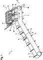
- FIG. 1 shows a transport arrangement 1 according to the embodiment.
- the transport arrangement 1 comprises a sliding device 2 and a conveying device 3 for transporting piece goods 4.
- the conveyor 3 is composed of a belt 6 and a plurality of vertically projecting from the belt 6 cell angles 5.
- the conveyor 3 is moved circumferentially in the indicated direction of movement.
- a cargo 4 In each case between two cell angles 5 is a cargo 4.
- the cargo 4 is located with one side to a cell angle 5 at. This is referred to as a sliding cell angle 5.
- the conveyor 3 In order to ensure a secure abutment of the piece goods 4 at the sliding cell angle 5, the conveyor 3 is partially employed at an angle greater than 0 degrees.
- a longitudinal oscillation with appropriately adapted acceleration ramps can preferably be impressed on the belt 6 via a servo drive.
- FIG. 1 furthermore shows a distance 9 between two adjacent cell angles 5 and a length 8 of the piece good 4.
- the distance 9 between the cell angles 5 no longer needs to be adjusted, since the sliding device 2 reacts flexibly to the length 8 of the piece goods 4.
- the distance 9 is greater than the length of the eighth
- the sliding device 2 comprises a plurality of driving units 10. Each of these driving units 10 has a paddle 11 and a slide 12. The sliding device 2 detects the position or size of the incoming piece goods 4. Then, a driving unit 10 is moved such that the Paddle 10 rests as a leading cell angle on piece goods 4. As a result, the position of the piece goods 4 is defined and via the slider 11, the cargo 4 can be deported from the conveyor 3. In particular, located next to the conveyor 3, a supply device on which a package, in particular a carton is located. As a result, the piece goods 4 are pushed directly from the conveyor 3 into the packaging with the slider 11.
- FIG. 2 shows the sliding device 1 in detail.
- the sliding device 2 comprises a base frame 13.
- This base frame 13 is formed oval.
- On the base frame 13 is a circumferential track 14, formed of frame-fixed guide rails.
- the track 14 represents an oval track for the driving units 10.
- the driving units 10 each have a plurality of rollers 15. About these rollers 15, the driving units 10 are guided on the track 14.
- the paddles 11 and slides 12 each move together with the respective driving unit 10.
- the driving units 10 along the marked direction of travel 17 can be arbitrarily positioned on the track 14 and moved.
- 13 several separately controllable magnetic coils are arranged in the base frame.
- a so-called electromagnetic traveling field is generated.
- the driving units 10 each include a permanent magnet, so that the driving units 10 can be positioned and moved via this electromagnetic traveling field.
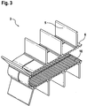
- FIG. 3 shows a section of the conveyor 3 in detail.
- the individual cell angles 5 are fixedly mounted on the belt 6.
- a toothing 16 for driving the conveyor 3 is formed on the inside of the belt 6.
- the belt 6 of the conveyor 3 in particular has mounting cams between which the cell angles 5 are inserted. This results in a highly resilient and in particular rigid coupling between the cell angles 5 and the band 6 both in the linear and in the deflection.
- the pushing device 2 is arranged as a "top runner" laterally next to the conveyor 3.
- the cell angle 5 act only sliding on the cargo 4.
- a trigger signal for the controller is generated.
- the synchronization of the driving units 10 takes place on the front edge of the cargo 4 and the application of the paddle to the cargo 4.
- the driving units can be synchronized via a drive 18 of the conveyor belt 6.
- the drive 18 is designed as a belt drive with integrated angle measuring system.
- the cargo 4 can be accommodated by a corresponding relative movement without play between the sliding cell angle 5 and the paddle 11.
- sliders 12 For sliding off or sliding over the slide 12 are provided.
- These sliders 12 may be passive drive elements, e.g. Guide switches, have, so as to be moved relative to the rest of the driving units 10 perpendicular to the direction of travel 17 can.
Description
Die vorliegende Erfindung betrifft eine Schiebeeinrichtung zum Abschieben von Stückgut von einer Fördereinrichtung und eine Transportanordnung mit einer Fördereinrichtung zum Transport von Stückgut und der Schiebeeinrichtung. Ferner betrifft die Erfindung eine Verpackungsanordnung mit der Transportanordnung und ein Verfahren zum Abschieben von Stückgut von einer Fördereinrichtung.The present invention relates to a sliding device for pushing piece goods from a conveyor and a transport arrangement with a conveyor for transporting piece goods and the sliding device. Furthermore, the invention relates to a packaging arrangement with the transport arrangement and a method for pushing out piece goods from a conveyor.
Bei Verpackungsanordnungen, insbesondere Kartoniermaschinen, werden die Produkte zunächst jeweils von einem Zellenwinkelpaar auf einem Transportsystem aufgenommen und schrittweise oder kontinuierlich dem eigentlichen Kartonierprozess zugeführt. Die schiebenden bzw. vorlaufenden Zellenwinkel sind jeweils mit zwei Rollenketten verbunden und können dadurch manuell durch Relativverschiebung der Ketten auf die entsprechende Produktbreite eingestellt werden. Dadurch werden die Produkte durch jeweils ein Zellenwinkelpaar aufgenommen. Bei konventionellen Kartoniermaschinen ist als Träger für die Faltschachteln und zur Unterstützung des Aufrichtprozesses eine zur Produktkette parallelgeschaltete und synchron laufende sogenannte Faltschachtelkette vorgesehen. Üblicherweise werden bei Kartoniermaschinen zum Überschub der Produkte in die geöffnete Faltschachtel folgende Einschubsysteme verwendet: Bekannt ist ein Trommeleinschub mit umlaufenden Einschubelementen synchron zur Packgutkette. Die Einschubelemente haben einen fixen Teilungsabstand und werden wegabhängig über Weichen axial verschoben. Des Weiteren ist eine reversierende Linearbewegung mehrerer Einschubelemente mit alternierenden Synchronlauf- und Gegenlaufphasen parallel zur Produktkette bekannt. In einer dritten Möglichkeit werden servomotorisch angetriebene Zwei- bzw. Mehrzugsysteme mit gegenläufig antreibbaren Einschubelementen parallel zur Produktkette verwendet. Die vorbekannten Kartoniermaschinen haben insbesondere folgende Nachteile: Es werden stets mehrere Meter lange Produktketten benötigt, die einen signifikanten Kostenfaktor darstellen. Des Weiteren bedarf es einer manuellen Einstellung der Produktzellenwinkel auf die Packgutbreite. Ferner sind stets Einschubprobleme beim Überschub des Packgutes in die Faltschachtel möglich, da für eine prozesssichere Produktzuführung in die Produktkette ein relativ großes Spiel zwischen den Zellenwinkeln der Produktkette und dem Produkt erforderlich ist.In packaging arrangements, in particular cartoning machines, the products are first taken in each case by a pair of cell angles on a transport system and supplied stepwise or continuously to the actual cartoning process. The sliding or leading cell angles are each connected to two roller chains and can be adjusted manually by relative displacement of the chains to the corresponding product width. As a result, the products are taken up by a pair of cell angles. In conventional cartoning is provided as a carrier for the cartons and to support the Aufrichtprozesses a parallel to the product chain and synchronously running so-called Faltschachtelkette. Usually, the following slide-in systems are used in cartoning machines for pushing the products into the opened folding carton: A drum insert with rotating insert elements is known synchronously with the packaged goods chain. The plug-in elements have a fixed pitch and are moved away depending on switches axially. Furthermore, a reversing linear movement of several insertion elements with alternating synchronous and counter running phases parallel to the product chain is known. In a third way will be servo-motor driven two or more traction systems with counter-drivable slide-in elements used parallel to the product chain. In particular, the previously known cartoning machines have the following disadvantages: There are always several meter long product chains needed, which represent a significant cost factor. Furthermore, a manual adjustment of the product cell angle to the package width is required. Furthermore, insertion problems are always possible when the packaged goods are pushed into the folding box, since a relatively large clearance between the cell angles of the product chain and the product is required for reliable product feeding into the product chain.
Aus der
Aus der
Die erfindungsgemäße Schiebeeinrichtung mit den Merkmalen des Anspruchs 1 ermöglicht im Gegensatz zu den vorbekannten Einrichtungen ein kosteneffizientes und sicheres Abschieben von Stückgut von einer Fördereinrichtung. Dabei erfolgt eine automatisierte Einstellung der gesamten Produktkette auf die Breite des Stückgutes. Es ist eine spielfreie Produktaufnahme möglich, wodurch ein prozesssicherer Abschub des Stückgutes bzw. ein prozesssicherer Überschub des Stückgutes in eine Faltschachtel möglich ist. Im Vergleich zu den herkömmlichen Einrichtungen weist die erfindungsgemäße Schiebeeinrichtung wesentlich geringere bewegte Massen auf. Es sind höhere Taktfrequenzen im Taktbetrieb möglich und es erfolgt ein schonungsvolles Produkthandling. All diese Vorteile werden erreicht durch eine Schiebeeinrichtung zum Abschieben von Stückgut von einer Fördereinrichtung, umfassend eine umlaufende Laufbahn und zumindest eine angetriebene, auf der Laufbahn verfahrbare Fahreinheit. Die Fahreinheit ist gegenüber der Laufbahn beweglich und kann an jede beliebige Stelle der Laufbahn verfahren werden. Die Fahreinheit umfasst ein Paddel und einen Schieber. Das Paddel und der Schieber sind fest auf einem Fahrgestell der Fahreinheit montiert und bewegen sich somit mit der gesamten Fahreinheit mit. Das Paddel ist zur Anlage an das auf der Fördereinrichtung ankommende Stückgut ausgebildet. Der Schieber ist senkrecht zur Fahrtrichtung der Fahreinheit verschiebbar. Dadurch kann mit dem Schieber das Stückgut von der Fördereinrichtung abgeschoben werden. Die Stückgüter können dabei intermittierend oder kontinuierlich mit der Fördereinrichtung zugeführt werden.The sliding device according to the invention with the features of claim 1 allows in contrast to the previously known devices, a cost-efficient and safe removal of cargo from a conveyor. An automated adjustment of the entire product chain to the width of the piece goods takes place. It is a backlash-free product recording possible, whereby a process-safe Abschub of the piece good or a process-safe Überub the piece good in a carton is possible. In comparison to the conventional devices, the sliding device according to the invention has much lower moving masses. There are higher clock frequencies in the cycle mode possible and there is a gentle product handling. All these advantages are achieved by a sliding device for pushing out piece goods from a conveyor, comprising a circumferential track and at least one driven, movable on the track driving unit. The driving unit is movable relative to the track and can be moved to any point of the track. The driving unit includes a paddle and a slider. The paddle and the slide are firmly mounted on a chassis of the driving unit and thus move with the entire drive unit. The paddle is designed to rest on the arriving on the conveyor piece goods. The slider is displaceable perpendicular to the direction of travel of the driving unit. As a result, the piece goods can be removed from the conveyor with the slider. The piece goods can be supplied intermittently or continuously with the conveyor.
Insbesondere handelt es sich um eine lineare Fördereinrichtung, beispielsweise ein Förderband oder eine umlaufende Kette oder ein umlaufender Riemen.In particular, it is a linear conveyor, such as a conveyor belt or a revolving chain or a rotating belt.
Die Unteransprüche zeigen bevorzugte Weiterbildungen der Erfindung.The dependent claims show preferred developments of the invention.
Es ist vorgesehen, dass die Fahreinheit mindestens einen Permanentmagneten umfasst und entlang der Laufbahn separat ansteuerbare Magnetspulen zum Antrieb der Fahreinheit angeordnet sind. Diese separat ansteuerbaren Magnetspulen erzeugen ein sogenanntes elektromagnetisches Wanderfeld und stellen einen Teil des Linearantriebs für die Fahreinheiten dar. Je nach Bestromung der Magnetspulen wird ein entsprechendes elektromagnetisches Feld erzeugt und eine magnetische Koppelung zwischen Magnetspule und Fahreinheit generiert. Dadurch kann die Fahreinheit an jeder beliebigen Stelle auf der Laufbahn positioniert werden. Insbesondere ist ein Positionserfassungssystem an der Schiebeeinrichtung vorgesehen, das die aktuelle Position der Fahreinheit auf der Laufschiene erfasst.It is provided that the driving unit comprises at least one permanent magnet and along the track separately controllable magnetic coils for driving the driving unit are arranged. These separately controllable magnetic coils generate a so-called electromagnetic traveling field and represent part of the linear drive for the driving units. Depending on the energization of the magnetic coils, a corresponding electromagnetic field is generated and generates a magnetic coupling between the magnetic coil and driving unit. This allows the driving unit to be positioned anywhere on the track. In particular, a position detection system is provided on the sliding device, which detects the current position of the driving unit on the running rail.
In besonders bevorzugter Ausführung ist das Paddel senkrecht zur Fahrtrichtung der Fahreinheit verschiebbar. Dadurch ist es möglich, die Schiebeeinrichtung direkt neben der Fördereinrichtung zu positionieren. Die Paddel werden dabei zwischen die Zellenwinkel auf der Fördereinrichtung eingeschleust. Hierzu werden die Paddel zunächst senkrecht zur Fahrtrichtung der Fahreinheit zurückgezogen und dann zwischen die Zellwinkel eingeschoben.In a particularly preferred embodiment, the paddle is displaceable perpendicular to the direction of travel of the driving unit. This makes it possible to position the sliding device directly next to the conveyor. The paddles are thereby introduced between the cell angles on the conveyor. For this purpose, the paddles are first withdrawn perpendicular to the direction of travel of the driving unit and then inserted between the cell angle.
Insbesondere ist vorgesehen, dass auf der Laufbahn vorzugsweise mindestens zwei Fahreinheiten angeordnet sind. Dabei ist jede Fahreinheit separat ansteuerbar, so dass eine Position der Fahreinheit auf der Laufbahn und ein Abstand zwischen benachbarten Fahreinheiten veränderbar ist. Dies ist insbesondere durch das elektromagnetische Wanderfeld und das Positionserfassungssystem möglich.In particular, it is provided that preferably at least two driving units are arranged on the track. In this case, each driving unit can be controlled separately, so that a position of the driving unit on the track and a distance between adjacent driving units can be changed. This is possible in particular by the electromagnetic traveling field and the position detection system.
Des Weiteren ist bevorzugt eine Erfassungseinheit zum Erfassen einer Position des ankommenden Stückgutes auf der Fördereinrichtung vorgesehen. Mittels dieser Erfassungseinheit erkennt die Schiebeeinrichtung die Position des ankommenden Stückgutes und kann eine der Fahreinheiten in Position bringen. Dabei wird die Fahreinheit derart in Position gebracht, dass das Paddel an einer Seite des Stückgutes anliegt.Furthermore, a detection unit is preferably provided for detecting a position of the arriving piece goods on the conveyor. By means of this detection unit detects the sliding device, the position of the incoming cargo and can bring one of the driving units in position. In this case, the driving unit is brought into position such that the paddle rests against one side of the piece goods.
Die Erfindung umfasst des Weiteren eine Transportanordnung mit einer Fördereinrichtung zum Transport von Stückgut und der soeben beschriebenen Schiebeeinrichtung. Die Fördereinrichtung umfasst zumindest einen Zellenwinkel. Insbesondere umfasst die Fördereinrichtung mehrere voneinander beabstandete Zellenwinkel, wobei jeweils zwischen zwei Zellenwinkeln eines der Stückgute angeordnet ist. Erfindungsgemäß muss jedoch der Abstand zwischen den Zellenwinkeln nicht mehr auf die Breite des Stückgutes angepasst werden. Das ankommende Stückgut liegt mit einer Seite an einem der Zellenwinkel an und die Fahreinheit wird derart gesteuert, dass das Paddel an der der ersten Seite gegenüberliegenden Seite des Stückgutes zur Anlage kommt. Dadurch ist eine gesicherte Position des Stückgutes festgelegt und der Schieber kann das Stückgut definiert abschieben.The invention further comprises a transport arrangement with a conveyor for transporting piece goods and the shifter just described. The conveyor comprises at least one cell angle. In particular, the conveyor device comprises a plurality of spaced-apart cell angles, one of the pieces good being arranged in each case between two cell angles. According to the invention, however, the distance between the cell angles no longer has to be adapted to the width of the piece good. The arriving piece goods abuts with one side at one of the cell angles and the driving unit is controlled such that the paddle comes to rest on the side of the piece goods opposite the first side. As a result, a secured position of the piece goods is set and the slider can deport the cargo defined.
Besonders bevorzugt ist vorgesehen, dass die Fahrtrichtung der Fahreinheit und die Bewegungsrichtung der Fördereinheit in zueinander parallelen Ebenen liegen. Die Laufbahn ist insbesondere oval ausgestaltet, wobei die beiden längeren Seiten des Ovals parallel zur Fördereinrichtung, insbesondere parallel zu einem Förderband, stehen.Particularly preferably, it is provided that the direction of travel of the drive unit and the direction of movement of the conveyor unit lie in mutually parallel planes. The track is configured in particular oval, wherein the two longer sides of the oval parallel to the conveyor, in particular parallel to a conveyor belt, are.
Die im Rahmen der erfindungsgemäßen Schiebeeinrichtung beschriebenen vorteilhaften Ausgestaltungen und Unteransprüche finden entsprechend vorteilhafte Anwendung auf die erfindungsgemäße Transportanordnung.The advantageous embodiments described in the context of the sliding device according to the invention and dependent claims find correspondingly advantageous application to the transport arrangement according to the invention.
Die Erfindung umfasst des Weiteren eine Verpackungsanordnung mit einer der soeben beschriebenen Transportanordnungen und einer Bereitstellungseinrichtung. Die Bereitstellungseinrichtung ist zum Bereitstellen einer Verpackung, insbesondere einer Faltschachtel, neben der Fördereinrichtung ausgebildet. Der Schieber ist zum Abschieben des Stückgutes von der Fördereinrichtung und zum gleichzeitigen Einschieben des Stückgutes in die Verpackung ausgebildet. Insbesondere handelt es sich bei der Verpackungsanordnung um eine Kartoniermaschine für die Verpackung von pharmazeutischen oder kosmetischen Erzeugnissen oder für Nahrungsmittel. Der eine Zellenwinkel auf der Fördereinrichtung und die Paddel der Fahreinheit definieren die genaue Position des Stückgutes, so dass über den Schieber das Stückgut exakt in die Verpackung eingeschoben werden kann.The invention further comprises a packaging arrangement with one of the transport arrangements and a delivery device just described. The supply device is designed to provide a packaging, in particular a folding box, next to the conveyor. The slider is designed for pushing the piece goods from the conveyor and for simultaneous insertion of the piece goods in the package. In particular, the packaging arrangement is a cartoning machine for the packaging of pharmaceutical or cosmetic products or for foodstuffs. The one cell angle on the conveyor and the paddles of the drive unit define the exact position of the piece goods so that the piece goods can be exactly inserted into the packaging via the slider.
Die im Rahmen der erfindungsgemäßen Schiebeeinrichtung und Transportanordnung beschriebenen vorteilhaften Ausgestaltungen und Unteransprüche finden entsprechend vorteilhafte Anwendung auf die erfindungsgemäße Verpackungsanordnung.The advantageous embodiments and subclaims described in the context of the sliding device and transport arrangement according to the invention accordingly find advantageous application to the packaging arrangement according to the invention.
Die Erfindung umfasst des Weiteren ein Verfahren zum Abschieben von Stückgut von einer Fördereinrichtung. Das Verfahren umfasst die folgenden Schritte: (i) Erfassen einer Position des ankommenden Stückgutes auf der Fördereinrichtung, (ii) Verfahren einer Fahreinheit auf einer umlaufenden Laufbahn, so dass ein Paddel der Fahreinheit am Stückgut anliegt, und (iii) Abschieben des Stückgutes mit einem Schieber der Fahreinheit. Insbesondere ist vorgesehen, dass die Fahreinheit nach dem Anlegen des Paddels am Stückgut mit derselben Geschwindigkeit wie die Fördereinrichtung verfahren wird. Dadurch fährt die Fahreinheit synchron mit dem auf der Fördereinrichtung beförderten Stückgut. Bei einem Verpacken des Stückgutes wird parallel zur Fördereinrichtung eine offene Verpackung ebenfalls mit derselben Geschwindigkeit bewegt, so dass während des Fortbewegens des Stückgutes das Stückgut verpackt werden kann.The invention further comprises a method for pushing out piece goods from a conveyor. The method comprises the following steps: (i) detecting a position of the incoming piece goods on the conveyor, (ii) moving a driving unit on a revolving track, so that a paddle of the driving unit abuts the piece goods, and (iii) pushing the piece good with a Slider of the driving unit. In particular, it is provided that the driving unit is moved after applying the paddle on the piece goods at the same speed as the conveyor. As a result, the driving unit moves synchronously with the piece goods transported on the conveyor. When packing the piece goods an open package is also moved at the same speed parallel to the conveyor, so that during the transportation of the piece goods, the piece goods can be packed.
Die im Rahmen der erfindungsgemäßen Schiebeeinrichtung, Transportanordnung oder Verpackungsanordnung beschriebenen vorteilhaften Ausgestaltungen und Unteransprüche finden in entsprechender Weise vorteilhafte Anwendung auf das erfindungsgemäße Verfahren.The advantageous embodiments and subclaims described in the context of the sliding device, transport arrangement or packaging arrangement according to the invention find correspondingly advantageous application to the method according to the invention.
Nachfolgend wird ein Ausführungsbeispiel der Erfindung unter Bezugnahme auf die begleitende Zeichnung im Detail beschrieben. Dabei zeigt:
- Figur 1
- eine erfindungsgemäße Transportanordnung gemäß einem Ausführungsbeispiel,
- Figur 2
- eine erfindungsgemäße Schiebeeinrichtung der erfindungsgemäßen Transportanordnung gemäß dem Ausführungsbeispiel, und
Figur 3- eine Fördereinrichtung der erfindungsgemäßen Transportanordnung gemäß dem Ausführungsbeispiel.
- FIG. 1
- a transport arrangement according to the invention according to an embodiment,
- FIG. 2
- a sliding device according to the invention of the transport arrangement according to the invention according to the embodiment, and
- FIG. 3
- a conveyor of the transport arrangement according to the invention according to the embodiment.
Die Fördereinrichtung 3 setzt sich zusammen aus einem Band 6 und mehreren von dem Band 6 senkrecht abstehenden Zellenwinkeln 5. Die Fördereinrichtung 3 wird in der eingezeichneten Bewegungsrichtung 7 umlaufend bewegt.The
Jeweils zwischen zwei Zellenwinkeln 5 befindet sich ein Stückgut 4. Das Stückgut 4 liegt mit einer Seite an einem Zellenwinkel 5 an. Man spricht hier von einem schiebenden Zellenwinkel 5. Um ein sicheres Anliegen des Stückgutes 4 am schiebenden Zellenwinkel 5 zu gewährleisten, ist die Fördereinrichtung 3 teilweise um einen Winkel größer 0 Grad angestellt. Zur Unterstützung des Anlageprozesses kann bevorzugt an dem Band 6 über einen Servoantrieb eine Longitudinalschwingung mit entsprechend angepassten Beschleunigungsrampen aufgeprägt werden.In each case between two
Die Schiebeeinrichtung 2 umfasst mehrere Fahreinheiten 10. Jede dieser Fahreinheiten 10 weist ein Paddel 11 und einen Schieber 12 auf. Die Schiebeeinrichtung 2 erkennt die Position bzw. Größe des ankommenden Stückgutes 4. Daraufhin wird eine Fahreinheit 10 derart verfahren, dass das Paddel 10 als vorlaufender Zellenwinkel am Stückgut 4 anliegt. Dadurch ist die Position des Stückgutes 4 definiert und über den Schieber 11 kann das Stückgut 4 von der Fördereinrichtung 3 abgeschoben werden. Insbesondere befindet sich neben der Fördereinrichtung 3 eine Bereitstellungseinrichtung, auf der sich eine Verpackung, insbesondere ein Karton, befindet. Dadurch wird mit dem Schieber 11 das Stückgut 4 direkt von der Fördereinrichtung 3 in die Verpackung geschoben.The sliding device 2 comprises a plurality of driving
Somit können die Fahreinheiten 10 entlang der eingezeichneten Fahrrichtung 17 beliebig auf der Laufbahn 14 positioniert und verfahren werden. Insbesondere sind im Grundgestell 13 mehrere separat ansteuerbare Magnetspulen angeordnet. Über diese Magnetspulen ist ein sogenanntes elektromagnetisches Wanderfeld erzeugbar. Die Fahreinheiten 10 umfassen jeweils einen Permanentmagneten, so dass die Fahreinheiten 10 über dieses elektromagnetische Wanderfeld positionierbar und verfahrbar sind.Thus, the driving
Gemäß diesem Ausführungsbeispiel ist die Schiebeeinrichtung 2 als "Oberläufer" seitlich neben der Fördereinrichtung 3 angeordnet. Die Zellenwinkel 5 wirken lediglich schiebend auf das Stückgut 4. Beim Einlauf des Stückgutes 4 in den Arbeitsbereich der Schiebeeinrichtung 2 wird, beispielsweise beim Durchfahren einer Lichtschranke, ein Triggersignal für die Steuerung generiert. Daran anschließend erfolgt die Synchronisierung der Fahreinheiten 10 auf die vordere Kante des Stückgutes 4 und das Anlegen des Paddels an das Stückgut 4. Alternativ können die Fahreinheiten auch über einen Antrieb 18 des Förderbandes 6 synchronisiert werden. Bevorzugt ist der Antrieb 18 als Bandantrieb mit integriertem Winkelmesssystem ausgebildet. Unmittelbar daran anschließend kann das Stückgut 4 durch eine entsprechende Relativbewegung spielfrei zwischen dem schiebenden Zellenwinkel 5 und dem Paddel 11 aufgenommen werden. Damit sind die Voraussetzungen für das Abschieben mit dem Schieber 11 bzw. das Einschieben in eine Verpackung erfüllt.According to this embodiment, the pushing device 2 is arranged as a "top runner" laterally next to the
Zum Ab- oder Überschieben sind die Schieber 12 vorgesehen. Diese Schieber 12 können passive Antriebselemente, z.B. Führungsweichen, aufweisen, um so relativ zum Rest der Fahreinheiten 10 senkrecht zur Fahrtrichtung 17 verschoben werden zu können. Allerdings ist es auch möglich, die Schieber 12 direkt mit Permanentmagneten auszustatten. Ferner benötigt es eines elektromagnetischen Wanderfeldes zur Bewegung dieser Permanentmagneten und der Schieber 12 senkrecht zur Fahrtrichtung 17.For sliding off or sliding over the
Claims (9)
- Slide device (2) for sliding piece goods (4) off a conveying device (3), comprising- a revolving track (14), and- at least one driven mobile unit (10) which is capable of travelling on the track (14),- wherein the mobile unit (10) comprises a paddle (11) for bearing on the piece goods (4) arriving on the conveying device (3), and- wherein the mobile unit (10) comprises a slider (12) which for sliding off the piece goods (4) from the conveying device (3) is displaceable in manner perpendicular to the travelling direction (17) of the mobile unit (10),characterized in that the mobile unit (10) comprises at least one permanent magnet, and that separately actuatable solenoids for driving the mobile unit (10) are disposed along the track (14).
- Slide device according to Claim 1, characterized in that the paddle (11) is displaceable in a manner perpendicular to the travelling direction (17) of the mobile unit (10).
- Slide device according to one of the preceding claims, characterized by a plurality of driven mobile units (10) which are capable of travelling on the track (14), wherein each mobile unit (10) is separately actuatable such that a position of the mobile unit (10) on the track and a spacing between adjacent mobile units (10) are variable.
- Slide device according to one of the preceding claims, characterized by a detection unit for detecting a position of the arriving piece goods (4) on the conveying device (3).
- Transport assembly (1) comprising a conveying device (3) for transporting piece goods (4) and a slide device (2) according to one of the preceding claims for sliding the piece goods (4) off the conveying device (3), wherein the conveying device (3) comprises at least one angular cell (5) for bearing on a first side of the piece goods (4), and the paddle (11) is configured so as to bear on a second side of the piece goods (4) that is opposite the first side.
- Transport assembly according to Claim 5, characterized in that the travelling direction (17) of the mobile unit and the moving direction (7) of the conveying device (3) are in mutually parallel planes.
- Packaging assembly comprising a transport assembly (1) according to one of Claims 5 or 6 and a provisioning device for providing a pack beside the conveying device (3), wherein the slide (12) is configured for sliding the piece goods (4) off the conveying device (3) and for simultaneously inserting the piece goods (4) into the pack.
- Method for sliding piece goods (4) off a conveying device (3), the method comprising the following steps:- detecting a position of the arriving piece goods (4) on the conveying device (3),- moving a mobile unit (10), which comprises at least one permanent magnet, on a revolving track (14) such that a paddle (11) of the mobile unit (10) bears on the piece goods (4) in that solenoids which are disposed along a track (14) are separately actuated for driving the mobile unit (10), and- sliding off the piece goods (4) by way of a slide of the mobile unit (10).
- Method according to Claim 8, characterized in that the mobile unit (10), once the paddle (11) bears on the piece goods (4), is moved at the same speed as the conveying device (3).
Applications Claiming Priority (2)
| Application Number | Priority Date | Filing Date | Title |
|---|---|---|---|
| DE102012205060A DE102012205060A1 (en) | 2012-03-29 | 2012-03-29 | Sliding device, transport arrangement and packaging arrangement |
| PCT/EP2013/052991 WO2013143772A1 (en) | 2012-03-29 | 2013-02-14 | Pushing device, transport arrangement and packaging arrangement |
Publications (2)
| Publication Number | Publication Date |
|---|---|
| EP2830957A1 EP2830957A1 (en) | 2015-02-04 |
| EP2830957B1 true EP2830957B1 (en) | 2016-04-20 |
Family
ID=47720514
Family Applications (1)
| Application Number | Title | Priority Date | Filing Date |
|---|---|---|---|
| EP13704604.1A Not-in-force EP2830957B1 (en) | 2012-03-29 | 2013-02-14 | Slide device, transport and packaging assembly |
Country Status (4)
| Country | Link |
|---|---|
| US (1) | US20150047295A1 (en) |
| EP (1) | EP2830957B1 (en) |
| DE (1) | DE102012205060A1 (en) |
| WO (1) | WO2013143772A1 (en) |
Families Citing this family (22)
| Publication number | Priority date | Publication date | Assignee | Title |
|---|---|---|---|---|
| CN103935553B (en) * | 2014-04-24 | 2016-01-20 | 泰兴市博越众科自动化设备有限公司 | A kind of automatic packaging machine medicine plate enters box device |
| EP3034415B1 (en) * | 2014-12-19 | 2017-03-22 | UHLMANN PAC-SYSTEME GmbH & Co. KG | Method for transferring articles to be packaged to containers and further transport of the filled containers |
| EP3034414B1 (en) * | 2014-12-19 | 2017-02-22 | UHLMANN PAC-SYSTEME GmbH & Co. KG | Method for transferring articles to be packaged to containers and further transport of the filled containers |
| WO2016107655A1 (en) | 2014-12-30 | 2016-07-07 | Gebo Packaging Solutions France | Device and method for delivering oriented elements |
| CN104627421B (en) * | 2015-02-10 | 2016-09-07 | 吴中经济技术开发区越溪斯特拉机械厂 | A kind of remote controller pusher of automatic remote controller baling press |
| US9688473B2 (en) | 2015-03-02 | 2017-06-27 | Lorin Reed | Conveying systems and methods of use |
| CN105668179B (en) * | 2016-03-02 | 2018-02-27 | 安徽省亮亮纺织有限公司 | One kind weaving roller Transporting equipment |
| CN206984426U (en) * | 2016-06-14 | 2018-02-09 | Jvm有限公司 | Drug packages equipment |
| CN105966667A (en) * | 2016-06-27 | 2016-09-28 | 昆山尚威包装科技有限公司 | Cubic material pushing device |
| DE102017109126A1 (en) * | 2017-04-27 | 2018-10-31 | Sig Technology Ag | Processing device and method for processing isolated packages |
| CN107512412B (en) * | 2017-07-19 | 2019-11-08 | 泉州台商投资区一创工业设计有限公司 | A kind of equipment for the automatic mounted box of LED light |
| IT201700089386A1 (en) | 2017-08-04 | 2019-02-04 | Azionaria Costruzioni Acma Spa | Equipment for packaging products inside cases |
| US10723492B2 (en) * | 2017-09-21 | 2020-07-28 | Yamato Corporation | Depositor apparatus |
| NZ765295A (en) | 2017-11-22 | 2023-02-24 | Lorin REED | Improved produce conveying and sizing equipment |
| DE102017129689A1 (en) | 2017-12-13 | 2019-06-13 | Krones Ag | cascade conveyor |
| DE102017129931A1 (en) | 2017-12-14 | 2019-06-19 | Krones Ag | cascade conveyor |
| EP3501878B1 (en) | 2017-12-22 | 2022-07-13 | B&R Industrial Automation GmbH | Transport device in the form of a linear motor with guideway stator |
| CN108688871A (en) * | 2018-04-24 | 2018-10-23 | 浙江迦南小蒋科技有限公司 | Fast-type rests the head on packet feeding device |
| CN110451012B (en) * | 2019-07-02 | 2021-10-15 | 广州市联柔机械设备有限公司 | Spring conveying device and bagged spring packaging device |
| CN110844173B (en) * | 2019-11-18 | 2021-04-30 | 杭州富阳新堰纸制品有限公司 | Conveying mechanism in packaging field |
| CN111573132A (en) * | 2020-05-25 | 2020-08-25 | 北京闼闼同创工贸有限公司 | Material supplying and discharging device |
| CN115092437A (en) * | 2022-07-25 | 2022-09-23 | 水羊化妆品制造有限公司 | Discharging and boxing device and boxing equipment |
Citations (1)
| Publication number | Priority date | Publication date | Assignee | Title |
|---|---|---|---|---|
| EP1992579A1 (en) * | 2007-05-14 | 2008-11-19 | Krones AG | Device for aligning containers with a conveyor track |
Family Cites Families (12)
| Publication number | Priority date | Publication date | Assignee | Title |
|---|---|---|---|---|
| SE403901B (en) * | 1976-12-07 | 1978-09-11 | Sundpacma Ab | METHOD AND DEVICE FOR PACKAGING GOODS UNITS IN SO-CALL WRAP-AROUND PACKAGING DURING CONTINUOUS MOVEMENT |
| DE3130308C2 (en) * | 1981-07-31 | 1984-11-29 | Stratec GmbH, 7534 Birkenfeld | Device for diverting defective products from a conveyor belt |
| US5079896A (en) * | 1989-05-25 | 1992-01-14 | H. J. Langen & Sons Inc. | Carton loading machine |
| GB9007853D0 (en) * | 1990-04-06 | 1990-06-06 | Emhart Ind | Push out device |
| DE9006297U1 (en) * | 1990-06-05 | 1990-09-06 | Rovema - Verpackungsmaschinen Gmbh, 6301 Fernwald, De | |
| IT1279730B1 (en) * | 1995-09-26 | 1997-12-16 | Azionaria Costruzioni Acma Spa | APPARATUS FOR PACKAGING PRODUCTS INSIDE CASES |
| DE20002411U1 (en) * | 2000-02-10 | 2001-06-13 | Horst Michael | Device for deflecting objects, in particular containers, from a movement path |
| DE10048007A1 (en) * | 2000-09-26 | 2002-04-11 | Iwk Verpackungstechnik Gmbh | Method and device for transferring a product in a packaging machine |
| IT1319594B1 (en) * | 2000-12-20 | 2003-10-20 | Cml Handling Technology S P A | EQUIPMENT AND METHOD FOR THE ACTIVATION AND CONTROL OF THE SORTING UNIT IN A SORTING MACHINE |
| DE102006049801A1 (en) * | 2006-10-23 | 2008-04-24 | Iwk Verpackungstechnik Gmbh | Product stack delivery controlling method for packaging machine, involves beginning delivery cycle in such manner that cell of conveyor adopts predetermined relative position relative to product stack at end of delivery cycle |
| US7631472B2 (en) * | 2007-03-01 | 2009-12-15 | Frederick Lidington | Integrated barrel loader and confiner apparatus for use in a cartoning system |
| DE102009029314A1 (en) * | 2009-01-29 | 2010-08-05 | Robert Bosch Gmbh | transport device |
-
2012
- 2012-03-29 DE DE102012205060A patent/DE102012205060A1/en not_active Withdrawn
-
2013
- 2013-02-14 WO PCT/EP2013/052991 patent/WO2013143772A1/en active Application Filing
- 2013-02-14 US US14/387,894 patent/US20150047295A1/en not_active Abandoned
- 2013-02-14 EP EP13704604.1A patent/EP2830957B1/en not_active Not-in-force
Patent Citations (1)
| Publication number | Priority date | Publication date | Assignee | Title |
|---|---|---|---|---|
| EP1992579A1 (en) * | 2007-05-14 | 2008-11-19 | Krones AG | Device for aligning containers with a conveyor track |
Also Published As
| Publication number | Publication date |
|---|---|
| EP2830957A1 (en) | 2015-02-04 |
| DE102012205060A1 (en) | 2013-10-02 |
| WO2013143772A1 (en) | 2013-10-03 |
| US20150047295A1 (en) | 2015-02-19 |
Similar Documents
| Publication | Publication Date | Title |
|---|---|---|
| EP2830957B1 (en) | Slide device, transport and packaging assembly | |
| EP3372538B1 (en) | Transport section, method for adjusting and/or configuring at least one transport line within a transport section and packaging plant | |
| EP2704967B1 (en) | Method for operating an electromagnetic transfer system, and transfer system | |
| DE102015103833B3 (en) | Improved transport system, in particular for a filling and closing device for pharmaceutical or cosmetic objects | |
| EP3521219B1 (en) | Transport device and method for adapting a transport device | |
| EP3260599B1 (en) | Device and method for switching passive points for transport systems with linear motors | |
| EP2634100B1 (en) | Tray sealer and method for transporting trays | |
| DE102005063193B4 (en) | Device and method for grouping piece goods | |
| EP3150521B1 (en) | Articles grouping device and method for changing the format of such a device | |
| DE102014214107A1 (en) | transport device | |
| EP3059190A1 (en) | Device and method for distributing and grouping containers | |
| EP1522508B2 (en) | Separating, synchronising and accumulating device | |
| EP0813494A1 (en) | Device for conveying products between different work stations | |
| EP3573910B1 (en) | Container-handling installation and method for conveying functional elements in a container-handling installation for the purpose of handling containers | |
| EP2865618B1 (en) | Apparatus for transferring stacks of blister packages | |
| EP2772445B1 (en) | Adjustment portal, shrinking device with adjustable shaft walls and method for adjusting shaft walls | |
| DE10123217A1 (en) | Assembly for packaging folded blister strips into cartons, has an insertion mechanism with push rods and an advance system with covering tongues moving across the material travel, and oscillation parallel to the movement | |
| EP3606850B1 (en) | Device for aligning products, more particularly for forming rows and/or groups of the products | |
| EP3375737B1 (en) | Transport section and method for adjusting and/or adjusting at least one transport line within a transport section | |
| DE202015104636U1 (en) | Handling device for general cargo | |
| DE19803297A1 (en) | Conveyer system for box-like packages with two facing parallel belts | |
| EP3390247B1 (en) | Transporting system for an installation, in particular a production, packaging, filling, assembly and/or processing installation | |
| EP3564136A1 (en) | Packaging machine with conveyor device | |
| DE60015143T2 (en) | Device for measuring a counted group of objects | |
| DE20315764U1 (en) | Goods packing machine, includes pair of drive parts for filling, synchronising and compacting goods |
Legal Events
| Date | Code | Title | Description |
|---|---|---|---|
| PUAI | Public reference made under article 153(3) epc to a published international application that has entered the european phase |
Free format text: ORIGINAL CODE: 0009012 |
|
| 17P | Request for examination filed |
Effective date: 20141029 |
|
| AK | Designated contracting states |
Kind code of ref document: A1 Designated state(s): AL AT BE BG CH CY CZ DE DK EE ES FI FR GB GR HR HU IE IS IT LI LT LU LV MC MK MT NL NO PL PT RO RS SE SI SK SM TR |
|
| AX | Request for extension of the european patent |
Extension state: BA ME |
|
| 17Q | First examination report despatched |
Effective date: 20150608 |
|
| DAX | Request for extension of the european patent (deleted) | ||
| GRAP | Despatch of communication of intention to grant a patent |
Free format text: ORIGINAL CODE: EPIDOSNIGR1 |
|
| INTG | Intention to grant announced |
Effective date: 20160108 |
|
| GRAS | Grant fee paid |
Free format text: ORIGINAL CODE: EPIDOSNIGR3 |
|
| GRAA | (expected) grant |
Free format text: ORIGINAL CODE: 0009210 |
|
| AK | Designated contracting states |
Kind code of ref document: B1 Designated state(s): AL AT BE BG CH CY CZ DE DK EE ES FI FR GB GR HR HU IE IS IT LI LT LU LV MC MK MT NL NO PL PT RO RS SE SI SK SM TR |
|
| REG | Reference to a national code |
Ref country code: GB Ref legal event code: FG4D Free format text: NOT ENGLISH |
|
| REG | Reference to a national code |
Ref country code: CH Ref legal event code: EP |
|
| REG | Reference to a national code |
Ref country code: AT Ref legal event code: REF Ref document number: 792151 Country of ref document: AT Kind code of ref document: T Effective date: 20160515 |
|
| REG | Reference to a national code |
Ref country code: IE Ref legal event code: FG4D Free format text: LANGUAGE OF EP DOCUMENT: GERMAN |
|
| REG | Reference to a national code |
Ref country code: DE Ref legal event code: R096 Ref document number: 502013002656 Country of ref document: DE |
|
| REG | Reference to a national code |
Ref country code: LT Ref legal event code: MG4D |
|
| REG | Reference to a national code |
Ref country code: NL Ref legal event code: MP Effective date: 20160420 |
|
| PG25 | Lapsed in a contracting state [announced via postgrant information from national office to epo] |
Ref country code: NO Free format text: LAPSE BECAUSE OF FAILURE TO SUBMIT A TRANSLATION OF THE DESCRIPTION OR TO PAY THE FEE WITHIN THE PRESCRIBED TIME-LIMIT Effective date: 20160720 Ref country code: LT Free format text: LAPSE BECAUSE OF FAILURE TO SUBMIT A TRANSLATION OF THE DESCRIPTION OR TO PAY THE FEE WITHIN THE PRESCRIBED TIME-LIMIT Effective date: 20160420 Ref country code: NL Free format text: LAPSE BECAUSE OF FAILURE TO SUBMIT A TRANSLATION OF THE DESCRIPTION OR TO PAY THE FEE WITHIN THE PRESCRIBED TIME-LIMIT Effective date: 20160420 Ref country code: PL Free format text: LAPSE BECAUSE OF FAILURE TO SUBMIT A TRANSLATION OF THE DESCRIPTION OR TO PAY THE FEE WITHIN THE PRESCRIBED TIME-LIMIT Effective date: 20160420 Ref country code: FI Free format text: LAPSE BECAUSE OF FAILURE TO SUBMIT A TRANSLATION OF THE DESCRIPTION OR TO PAY THE FEE WITHIN THE PRESCRIBED TIME-LIMIT Effective date: 20160420 |
|
| PG25 | Lapsed in a contracting state [announced via postgrant information from national office to epo] |
Ref country code: GR Free format text: LAPSE BECAUSE OF FAILURE TO SUBMIT A TRANSLATION OF THE DESCRIPTION OR TO PAY THE FEE WITHIN THE PRESCRIBED TIME-LIMIT Effective date: 20160721 Ref country code: PT Free format text: LAPSE BECAUSE OF FAILURE TO SUBMIT A TRANSLATION OF THE DESCRIPTION OR TO PAY THE FEE WITHIN THE PRESCRIBED TIME-LIMIT Effective date: 20160822 Ref country code: RS Free format text: LAPSE BECAUSE OF FAILURE TO SUBMIT A TRANSLATION OF THE DESCRIPTION OR TO PAY THE FEE WITHIN THE PRESCRIBED TIME-LIMIT Effective date: 20160420 Ref country code: LV Free format text: LAPSE BECAUSE OF FAILURE TO SUBMIT A TRANSLATION OF THE DESCRIPTION OR TO PAY THE FEE WITHIN THE PRESCRIBED TIME-LIMIT Effective date: 20160420 Ref country code: ES Free format text: LAPSE BECAUSE OF FAILURE TO SUBMIT A TRANSLATION OF THE DESCRIPTION OR TO PAY THE FEE WITHIN THE PRESCRIBED TIME-LIMIT Effective date: 20160420 Ref country code: SE Free format text: LAPSE BECAUSE OF FAILURE TO SUBMIT A TRANSLATION OF THE DESCRIPTION OR TO PAY THE FEE WITHIN THE PRESCRIBED TIME-LIMIT Effective date: 20160420 Ref country code: HR Free format text: LAPSE BECAUSE OF FAILURE TO SUBMIT A TRANSLATION OF THE DESCRIPTION OR TO PAY THE FEE WITHIN THE PRESCRIBED TIME-LIMIT Effective date: 20160420 |
|
| REG | Reference to a national code |
Ref country code: DE Ref legal event code: R097 Ref document number: 502013002656 Country of ref document: DE |
|
| PG25 | Lapsed in a contracting state [announced via postgrant information from national office to epo] |
Ref country code: DK Free format text: LAPSE BECAUSE OF FAILURE TO SUBMIT A TRANSLATION OF THE DESCRIPTION OR TO PAY THE FEE WITHIN THE PRESCRIBED TIME-LIMIT Effective date: 20160420 Ref country code: SK Free format text: LAPSE BECAUSE OF FAILURE TO SUBMIT A TRANSLATION OF THE DESCRIPTION OR TO PAY THE FEE WITHIN THE PRESCRIBED TIME-LIMIT Effective date: 20160420 Ref country code: EE Free format text: LAPSE BECAUSE OF FAILURE TO SUBMIT A TRANSLATION OF THE DESCRIPTION OR TO PAY THE FEE WITHIN THE PRESCRIBED TIME-LIMIT Effective date: 20160420 Ref country code: CZ Free format text: LAPSE BECAUSE OF FAILURE TO SUBMIT A TRANSLATION OF THE DESCRIPTION OR TO PAY THE FEE WITHIN THE PRESCRIBED TIME-LIMIT Effective date: 20160420 Ref country code: RO Free format text: LAPSE BECAUSE OF FAILURE TO SUBMIT A TRANSLATION OF THE DESCRIPTION OR TO PAY THE FEE WITHIN THE PRESCRIBED TIME-LIMIT Effective date: 20160420 |
|
| PLBE | No opposition filed within time limit |
Free format text: ORIGINAL CODE: 0009261 |
|
| STAA | Information on the status of an ep patent application or granted ep patent |
Free format text: STATUS: NO OPPOSITION FILED WITHIN TIME LIMIT |
|
| PG25 | Lapsed in a contracting state [announced via postgrant information from national office to epo] |
Ref country code: SM Free format text: LAPSE BECAUSE OF FAILURE TO SUBMIT A TRANSLATION OF THE DESCRIPTION OR TO PAY THE FEE WITHIN THE PRESCRIBED TIME-LIMIT Effective date: 20160420 |
|
| 26N | No opposition filed |
Effective date: 20170123 |
|
| PG25 | Lapsed in a contracting state [announced via postgrant information from national office to epo] |
Ref country code: SI Free format text: LAPSE BECAUSE OF FAILURE TO SUBMIT A TRANSLATION OF THE DESCRIPTION OR TO PAY THE FEE WITHIN THE PRESCRIBED TIME-LIMIT Effective date: 20160420 Ref country code: BE Free format text: LAPSE BECAUSE OF NON-PAYMENT OF DUE FEES Effective date: 20170228 |
|
| PG25 | Lapsed in a contracting state [announced via postgrant information from national office to epo] |
Ref country code: MC Free format text: LAPSE BECAUSE OF FAILURE TO SUBMIT A TRANSLATION OF THE DESCRIPTION OR TO PAY THE FEE WITHIN THE PRESCRIBED TIME-LIMIT Effective date: 20160420 |
|
| GBPC | Gb: european patent ceased through non-payment of renewal fee |
Effective date: 20170214 |
|
| REG | Reference to a national code |
Ref country code: IE Ref legal event code: MM4A |
|
| REG | Reference to a national code |
Ref country code: FR Ref legal event code: ST Effective date: 20171031 |
|
| PG25 | Lapsed in a contracting state [announced via postgrant information from national office to epo] |
Ref country code: LU Free format text: LAPSE BECAUSE OF NON-PAYMENT OF DUE FEES Effective date: 20170214 |
|
| PG25 | Lapsed in a contracting state [announced via postgrant information from national office to epo] |
Ref country code: FR Free format text: LAPSE BECAUSE OF NON-PAYMENT OF DUE FEES Effective date: 20170228 |
|
| REG | Reference to a national code |
Ref country code: BE Ref legal event code: MM Effective date: 20170228 |
|
| PG25 | Lapsed in a contracting state [announced via postgrant information from national office to epo] |
Ref country code: IE Free format text: LAPSE BECAUSE OF NON-PAYMENT OF DUE FEES Effective date: 20170214 Ref country code: GB Free format text: LAPSE BECAUSE OF NON-PAYMENT OF DUE FEES Effective date: 20170214 |
|
| PG25 | Lapsed in a contracting state [announced via postgrant information from national office to epo] |
Ref country code: MT Free format text: LAPSE BECAUSE OF FAILURE TO SUBMIT A TRANSLATION OF THE DESCRIPTION OR TO PAY THE FEE WITHIN THE PRESCRIBED TIME-LIMIT Effective date: 20160420 |
|
| PG25 | Lapsed in a contracting state [announced via postgrant information from national office to epo] |
Ref country code: AL Free format text: LAPSE BECAUSE OF FAILURE TO SUBMIT A TRANSLATION OF THE DESCRIPTION OR TO PAY THE FEE WITHIN THE PRESCRIBED TIME-LIMIT Effective date: 20160420 |
|
| REG | Reference to a national code |
Ref country code: AT Ref legal event code: MM01 Ref document number: 792151 Country of ref document: AT Kind code of ref document: T Effective date: 20180214 |
|
| PG25 | Lapsed in a contracting state [announced via postgrant information from national office to epo] |
Ref country code: AT Free format text: LAPSE BECAUSE OF NON-PAYMENT OF DUE FEES Effective date: 20180214 |
|
| PG25 | Lapsed in a contracting state [announced via postgrant information from national office to epo] |
Ref country code: HU Free format text: LAPSE BECAUSE OF FAILURE TO SUBMIT A TRANSLATION OF THE DESCRIPTION OR TO PAY THE FEE WITHIN THE PRESCRIBED TIME-LIMIT; INVALID AB INITIO Effective date: 20130214 |
|
| PG25 | Lapsed in a contracting state [announced via postgrant information from national office to epo] |
Ref country code: BG Free format text: LAPSE BECAUSE OF FAILURE TO SUBMIT A TRANSLATION OF THE DESCRIPTION OR TO PAY THE FEE WITHIN THE PRESCRIBED TIME-LIMIT Effective date: 20160420 |
|
| PG25 | Lapsed in a contracting state [announced via postgrant information from national office to epo] |
Ref country code: CY Free format text: LAPSE BECAUSE OF FAILURE TO SUBMIT A TRANSLATION OF THE DESCRIPTION OR TO PAY THE FEE WITHIN THE PRESCRIBED TIME-LIMIT Effective date: 20160420 |
|
| PG25 | Lapsed in a contracting state [announced via postgrant information from national office to epo] |
Ref country code: MK Free format text: LAPSE BECAUSE OF FAILURE TO SUBMIT A TRANSLATION OF THE DESCRIPTION OR TO PAY THE FEE WITHIN THE PRESCRIBED TIME-LIMIT Effective date: 20160420 |
|
| PG25 | Lapsed in a contracting state [announced via postgrant information from national office to epo] |
Ref country code: TR Free format text: LAPSE BECAUSE OF FAILURE TO SUBMIT A TRANSLATION OF THE DESCRIPTION OR TO PAY THE FEE WITHIN THE PRESCRIBED TIME-LIMIT Effective date: 20160420 |
|
| REG | Reference to a national code |
Ref country code: DE Ref legal event code: R082 Ref document number: 502013002656 Country of ref document: DE Representative=s name: DREISS PATENTANWAELTE PARTG MBB, DE Ref country code: DE Ref legal event code: R081 Ref document number: 502013002656 Country of ref document: DE Owner name: SYNTEGON TECHNOLOGY GMBH, DE Free format text: FORMER OWNER: ROBERT BOSCH PACKAGING TECHNOLOGY GMBH, 71332 WAIBLINGEN, DE Ref country code: DE Ref legal event code: R081 Ref document number: 502013002656 Country of ref document: DE Owner name: SYNTEGON TECHNOLOGY GMBH, DE Free format text: FORMER OWNER: ROBERT BOSCH GMBH, 70469 STUTTGART, DE |
|
| PG25 | Lapsed in a contracting state [announced via postgrant information from national office to epo] |
Ref country code: IS Free format text: LAPSE BECAUSE OF FAILURE TO SUBMIT A TRANSLATION OF THE DESCRIPTION OR TO PAY THE FEE WITHIN THE PRESCRIBED TIME-LIMIT Effective date: 20160820 |
|
| REG | Reference to a national code |
Ref country code: CH Ref legal event code: PUE Owner name: SYNTEGON TECHNOLOGY GMBH, DE Free format text: FORMER OWNER: ROBERT BOSCH GMBH, DE |
|
| PGFP | Annual fee paid to national office [announced via postgrant information from national office to epo] |
Ref country code: CH Payment date: 20210222 Year of fee payment: 9 Ref country code: IT Payment date: 20210226 Year of fee payment: 9 |
|
| PGFP | Annual fee paid to national office [announced via postgrant information from national office to epo] |
Ref country code: DE Payment date: 20210223 Year of fee payment: 9 |
|
| REG | Reference to a national code |
Ref country code: DE Ref legal event code: R119 Ref document number: 502013002656 Country of ref document: DE |
|
| REG | Reference to a national code |
Ref country code: CH Ref legal event code: PL |
|
| PG25 | Lapsed in a contracting state [announced via postgrant information from national office to epo] |
Ref country code: LI Free format text: LAPSE BECAUSE OF NON-PAYMENT OF DUE FEES Effective date: 20220228 Ref country code: DE Free format text: LAPSE BECAUSE OF NON-PAYMENT OF DUE FEES Effective date: 20220901 Ref country code: CH Free format text: LAPSE BECAUSE OF NON-PAYMENT OF DUE FEES Effective date: 20220228 |
|
| PG25 | Lapsed in a contracting state [announced via postgrant information from national office to epo] |
Ref country code: IT Free format text: LAPSE BECAUSE OF NON-PAYMENT OF DUE FEES Effective date: 20220214 |