EP2830474B1 - Saugschlauchspeichersystem - Google Patents
Saugschlauchspeichersystem Download PDFInfo
- Publication number
- EP2830474B1 EP2830474B1 EP13769460.0A EP13769460A EP2830474B1 EP 2830474 B1 EP2830474 B1 EP 2830474B1 EP 13769460 A EP13769460 A EP 13769460A EP 2830474 B1 EP2830474 B1 EP 2830474B1
- Authority
- EP
- European Patent Office
- Prior art keywords
- vacuum
- storage tube
- vacuum hose
- hose
- storage
- Prior art date
- Legal status (The legal status is an assumption and is not a legal conclusion. Google has not performed a legal analysis and makes no representation as to the accuracy of the status listed.)
- Active
Links
Images




Classifications
-
- A—HUMAN NECESSITIES
- A47—FURNITURE; DOMESTIC ARTICLES OR APPLIANCES; COFFEE MILLS; SPICE MILLS; SUCTION CLEANERS IN GENERAL
- A47L—DOMESTIC WASHING OR CLEANING; SUCTION CLEANERS IN GENERAL
- A47L9/00—Details or accessories of suction cleaners, e.g. mechanical means for controlling the suction or for effecting pulsating action; Storing devices specially adapted to suction cleaners or parts thereof; Carrying-vehicles specially adapted for suction cleaners
- A47L9/0009—Storing devices ; Supports, stands or holders
- A47L9/0063—External storing devices; Stands, casings or the like for the storage of suction cleaners
-
- A—HUMAN NECESSITIES
- A47—FURNITURE; DOMESTIC ARTICLES OR APPLIANCES; COFFEE MILLS; SPICE MILLS; SUCTION CLEANERS IN GENERAL
- A47L—DOMESTIC WASHING OR CLEANING; SUCTION CLEANERS IN GENERAL
- A47L5/00—Structural features of suction cleaners
- A47L5/12—Structural features of suction cleaners with power-driven air-pumps or air-compressors, e.g. driven by motor vehicle engine vacuum
- A47L5/22—Structural features of suction cleaners with power-driven air-pumps or air-compressors, e.g. driven by motor vehicle engine vacuum with rotary fans
- A47L5/38—Built-in suction cleaner installations, i.e. with fixed tube system to which, at different stations, hoses can be connected
-
- A—HUMAN NECESSITIES
- A47—FURNITURE; DOMESTIC ARTICLES OR APPLIANCES; COFFEE MILLS; SPICE MILLS; SUCTION CLEANERS IN GENERAL
- A47L—DOMESTIC WASHING OR CLEANING; SUCTION CLEANERS IN GENERAL
- A47L9/00—Details or accessories of suction cleaners, e.g. mechanical means for controlling the suction or for effecting pulsating action; Storing devices specially adapted to suction cleaners or parts thereof; Carrying-vehicles specially adapted for suction cleaners
- A47L9/24—Hoses or pipes; Hose or pipe couplings
- A47L9/248—Parts, details or accessories of hoses or pipes
-
- B—PERFORMING OPERATIONS; TRANSPORTING
- B65—CONVEYING; PACKING; STORING; HANDLING THIN OR FILAMENTARY MATERIAL
- B65H—HANDLING THIN OR FILAMENTARY MATERIAL, e.g. SHEETS, WEBS, CABLES
- B65H75/00—Storing webs, tapes, or filamentary material, e.g. on reels
- B65H75/02—Cores, formers, supports, or holders for coiled, wound, or folded material, e.g. reels, spindles, bobbins, cop tubes, cans, mandrels or chucks
- B65H75/34—Cores, formers, supports, or holders for coiled, wound, or folded material, e.g. reels, spindles, bobbins, cop tubes, cans, mandrels or chucks specially adapted or mounted for storing and repeatedly paying-out and re-storing lengths of material provided for particular purposes, e.g. anchored hoses, power cables
- B65H75/36—Cores, formers, supports, or holders for coiled, wound, or folded material, e.g. reels, spindles, bobbins, cop tubes, cans, mandrels or chucks specially adapted or mounted for storing and repeatedly paying-out and re-storing lengths of material provided for particular purposes, e.g. anchored hoses, power cables without essentially involving the use of a core or former internal to a stored package of material, e.g. with stored material housed within casing or container, or intermittently engaging a plurality of supports as in sinuous or serpentine fashion
- B65H75/362—Cores, formers, supports, or holders for coiled, wound, or folded material, e.g. reels, spindles, bobbins, cop tubes, cans, mandrels or chucks specially adapted or mounted for storing and repeatedly paying-out and re-storing lengths of material provided for particular purposes, e.g. anchored hoses, power cables without essentially involving the use of a core or former internal to a stored package of material, e.g. with stored material housed within casing or container, or intermittently engaging a plurality of supports as in sinuous or serpentine fashion with stored material housed within a casing or container
-
- B—PERFORMING OPERATIONS; TRANSPORTING
- B65—CONVEYING; PACKING; STORING; HANDLING THIN OR FILAMENTARY MATERIAL
- B65H—HANDLING THIN OR FILAMENTARY MATERIAL, e.g. SHEETS, WEBS, CABLES
- B65H2701/00—Handled material; Storage means
- B65H2701/30—Handled filamentary material
- B65H2701/33—Hollow or hose-like material
-
- Y—GENERAL TAGGING OF NEW TECHNOLOGICAL DEVELOPMENTS; GENERAL TAGGING OF CROSS-SECTIONAL TECHNOLOGIES SPANNING OVER SEVERAL SECTIONS OF THE IPC; TECHNICAL SUBJECTS COVERED BY FORMER USPC CROSS-REFERENCE ART COLLECTIONS [XRACs] AND DIGESTS
- Y10—TECHNICAL SUBJECTS COVERED BY FORMER USPC
- Y10T—TECHNICAL SUBJECTS COVERED BY FORMER US CLASSIFICATION
- Y10T29/00—Metal working
- Y10T29/49—Method of mechanical manufacture
- Y10T29/49716—Converting
Definitions
- the invention relates to vacuum hose storage systems.
- Central vacuum cleaners are commonly installed in homes, commercial establishments, and industrial facilities. Central vacuum cleaners typically comprise a vacuum unit configured to generate a partial vacuum and thereby induce a flow of air through a flexible vacuum hose.
- the vacuum unit is typically permanently mounted in a fixed location.
- the vacuum hose can either connect directly to the vacuum unit, or connect to one of one or more inlets which are connected to the vacuum unit by piping.
- the vacuum hose may be maneuvered to collect material via suction at an open end of the vacuum hose.
- This material may include dirt, dust, debris, liquid, etc.
- the collected material is sucked through the vacuum hose and into a filter or a receptacle.
- the vacuum hose should be long enough to reach from one or more vacuum inlets to all the areas that a user may wish to clean. In some situations, a very long vacuum hose will be required.
- a vacuum hose can be inconvenient to store.
- a user may have to manually coil a vacuum hose.
- a user may have to find an appropriate storage location for a vacuum hose. In many places, especially apartments, there may be insufficient space to conveniently store a vacuum hose.
- US 2011/0041282 A1 discloses an apparatus according to the preamble of claim 1.
- the vacuum unit is located within the upper section.
- the vacuum hose storage system comprises a vacpan.
- the vacpan comprises an opening in the kickboard; the opening is substantially at floor level; and the vacpan is fluidly connected to the vacuum unit such that the vacuum unit is operable to generate a pattial vacuum within the vacpan.
- the vacuum hose storage system comprises a cap, and the cap is attachable to one end of the vacuum hose to create a substantially airtight seal.
- the vacuum hose storage system comprises a pipe and an inlet, and the pipe is fluidly connected at one end to the vacuum unit and at the other end to the inlet.
- the vacuum hose is fluidly connectable to the inlet such that the vacuum unit is operable to generate a partial vacuum within the vacuum hose.
- the vacuum hose storage system comprises a storage tube opening located at the end of the storage tube.
- the storage tube opening is located within 5 feet (1.52 metres) of the inlet.
- the vacuum hose storage system comprises a plurality of pipes and inlets.
- the storage tube comprises two straight sides and two curved sides.
- the storage tube comprises PVC piping.
- the PVC piping is joined by male-female connections.
- Another non-limiting aspect of the invention provides a method for retrofitting a cabinet with a central vacuum cleaner according to claim 12.
- FIG. 1 illustrates a vacuum hose storage system 10 according to an example embodiment of the invention.
- a vacuum unit 11 is mounted within a cabinet 14, which may be a kitchen cabinet, a bathroom cabinet, or any other similar structure.
- cabinet 14 is box-like, with two sections, an upper section 50 and a lower section 52 forming the base of cabinet 14.
- Upper section 50 is generally accessible to a user.
- Lower section 52 is generally not accessible to a user.
- Lower section 52 is fronted by a kickboard 16.
- Vacuum unit 11 is mounted within upper section 50.
- Upper and lower sections 50, 52 are separated by a board 54.
- lower section 52 is empty. Vacuum hose storage system 10 makes use of this previously unused space.
- Figure 1 is an isometric view, taken from beneath the floor on which the cabinet sits. Neither the floor nor the cabinet doors are shown in order to more clearly illustrate the features of the invention within cabinet 14.
- vacuum hose storage system 10 may be mounted inside a wall, a specially designed enclosure, a basement, a garage, an attic or any other suitable location.
- a storage tube 19 is located within lower section 52 of cabinet 14 and behind kickboard 16. In the illustrated embodiment, storage tube 19 is fluidly connected to a vacpan pipe 21. Vacpan pipe 21 is fluidly connected to vacuum unit 11. The connection of vacpan pipe 21 to vacuum unit 11 is visible in Figures 2 and 3 . Operation of vacuum unit 11 is operable to generate a partial vacuum within vacpan pipe 21 and storage tube 19.
- Vacpan pipe 21 is fluidly connected to a vacpan 27.
- Vacpan 27 is mounted within kickboard 16 at floor level.
- Vacpan 27 comprises an opening with one edge that is substantially flush with the floor. The opening is normally covered, but when in operation it is uncovered and then dust, dirt, debris, liquid, etc. can be swept near vacpan 27 so that it may be sucked up through vacpan 27 and into vacpan pipe 21.
- Vacpan 27 may thereby operate as an alternative to a conventional dustpan.
- storage tube 19 may be fluidly connected to vacuum unit 11 directly. In other embodiments, storage tube 19 may be fluidly connected to vacuum unit 11 indirectly by other means, such as a pipe which is not vacpan pipe 21.
- storage tube 19 may be located within a wall, a specially designed enclosure, a basement, a garage, an attic, or any other suitable location. In some other examples not within the scope of the claims, storage tube 19 is located at a significant distance from vacuum unit 11. For example, vacuum unit 11 may be in the garage of a house and storage tube 19 may be within a cabinet of the kitchen of the house. In examples not within the scope of the claims where storage tube 19 is located a significant distance from vacuum unit 11, a long pipe may be used to fluidly connect storage tube 19 to vacuum unit 11.
- storage tube 19 forms the approximate shape of a running track (i.e. two relatively longer straight sides and two relatively shorter curved sides). In other embodiments, storage tube 19 may form other shapes, such as oval, circular, or spiral. It may be advantageous for storage tube 19 to have a shape with minimal curvature. Excessive curvature may inhibit the smooth insertion and withdrawal of a vacuum hose (not shown) from storage tube 19. It may also be advantageous for storage tube 19 to take up relatively little space. It may also be advantageous for storage tube 19 to take up relatively little vertical space so that it may fit within lower section 52 of cabinet 14.
- Storage tube 19 has a storage tube opening 22.
- storage tube opening 22 is mounted within the front of cabinet 14.
- a storage tube opening cover 24 is operable to cover storage tube opening 22.
- storage tube opening cover 24 forms a substantially airtight seal over storage tube opening 22.
- storage tube opening cover 24 is flexibly mounted adjacent to storage tube opening 22. In some embodiments, storage tube opening cover 24 can close automatically.
- Figure 2 is a perspective view of the vacuum hose storage system 10 in Figure 1 .
- Figure 3 is a cut away view of the vacuum hose storage system 10 in Figure 1 .
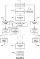
- FIG 4 is a schematic diagram of the vacuum hose storage system in Figure 1 .
- Lines with arrows indicate fluid connections. Dotted lines with arrows indicate possible fluid connections depending on how the vacuum hose is being used at a particular time.
- vacuum unit 11 is fluidly connected to vacpan pipe 21, which is fluidly connected to storage tube 19 and vacpan 27.
- Storage tube 19 has a storage tube opening 22.
- Vacuum pipes 31A and 31B are fluidly connected to vacuum unit 11. Vacuum unit 11 is operable to generate a partial vacuum within vacuum pipes 31A and 31B and storage tube opening 22. In other embodiments there may be other numbers of vacuum pipes, for example any number from 1 to 10.
- Vacuum pipes 31A and 31B arc fluidly connected to vacuum inlets 32A and 32B, respectively.
- Vacuum inlets 32A and 32B may be located a significant distance from vacuum unit 11.
- vacuum unit 11 may be located in the garage of a house
- vacuum inlet 32A may be located in the upstairs bedroom of the house
- vacuum inlet 32B may be located in the living room of the house.
- vacuum inlet 32A, or storage tube opening 22, or both are located very close to vacuum unit 11, for example within 10, 5, or 2 feet (3.048, 1.524, or 0.6096 metres). In some embodiments, vacuum inlet 32A is located very close to storage tube opening 22, for example within 10, 5, or 2 feet (3.048, 1.524, or 0.6096 metres).
- Vacuum inlets 32A and 32B may have vacuum inlet covers 33A and 33B, respectively.
- Vacuum inlet covers 33A and 33B may be operable to cover vacuum inlets 32A and 32B to form substantially airtight seals.
- these covers may be pivotally mounted adjacent to vacuum inlets 32A and 32B, respectively.
- these covers may be spring-loaded hinged covers which tend to cover the vacuum inlets if not urged open by a user.
- Vacuum hose 35 can be fluidly connected to vacuum inlet 32A or vacuum inlet 32B.
- vacuum unit 11 is operable to generate a partial vacuum within vacuum hose 35.
- Vacuum hose 35 can be used to suck up dust, dirt, debris, liquid, etc.
- Vacuum hose 35 has a smaller exterior diameter than the interior diameter of storage tube 19.
- vacuum hose 35 has an exterior diameter of 1.75 inches (4.445 centimetres) and storage tube 19 has an interior diameter of 2 inches (5.08 centimetres) or 1.875 inches (4.7625 centimetres).
- vacuum hose 35 has a length that is approximately equal to, or very slightly longer than (e.g. approximately 1.5 inches (3.81 centimetres) longer than), the length of storage tube 19. These relative dimensions allow vacuum hose 35 to fit inside storage tube 19, but not entirely.
- the vacuum hose 35 can also be fitted with a collar (not shown) to prevent the hose 35 from slipping irretrievably into storage tube 19.
- a stop can be provided within storage tube 19.
- storage tube 19 can have a radial restriction at some point near its inner end to prevent vacuum hose 35 from slipping irretrievably into storage tube 19.
- vacuum hose 35 To store vacuum hose 35, a user may place a portion of vacuum hose 35 through storage tube opening 22 and into storage tube 19. Operation of vacuum unit 11 generates a partial vacuum within storage tube 19, sucking vacuum hose 35 into storage tube 19. Vacuum hose 35 is flexible and bends to conform to the shape of storage tube 19.
- a vacuum hose cap 38 can be used to provide a substantially airtight seal over one end of vacuum hose 35. Vacuum hose cap 38 prevents air from flowing through vacuum hose 35, increasing the force of suction on vacuum hose 35 as it is sucked into storage tube 19. This may decrease the amount of time it takes for vacuum hose 35 to be sucked into storage tube 19. Vacuum hose cap 38 is removable, and is removed while vacuum hose 35 is being used for vacuuming.
- a user may place his or her hand over the free end of vacuum hose 35 in order to increase the force of suction on vacuum hose 35.
- Vacuum inlets 33A and 33B may be provided to seal vacuum inlets 32A and 32B, respectively . In some embodiments, it may be necessary to close vacuum inlet covers 33A and 33B in order for there to be sufficient suction at storage tube opening 22 to suck vacuum hose 35 into storage tube 19.
- the user may pull vacuum hose 35 out of storage tube 19 through storage tube opening 22. Then the user may connect an end of vacuum hose 35 to vacuum inlet 32A or 32B. Then the user may turn on vacuum unit 11 to generate a partial vacuum within vacuum hose 35.
- vacuum inlet cover 33A will be used to cover vacuum inlet 32A whenever vacuum hose 35 is not connected to vacuum inlet 32A.
- vacuum inlet cover 33B will be used to cover vacuum inlet 32B whenever vacuum hose 35 is not connected to vacuum inlet 32B.
- storage tube opening cover 24 will be used to cover storage tube opening 22 whenever vacuum hose 35 is connected to vacuum inlet 32A or 32B.
- FIG. 5 illustrates an example embodiment of storage tube opening 22.
- Recessed portion 25 may be recessed into or attached to cabinet wall 15.
- Storage tube opening 22 is mounted within the recessed portion 25 of cabinet wall 15.
- Vacuum hose 35 is shown fully inserted into storage tube 19.
- vacuum hose 35 is slightly longer than storage tube 19 so that a small portion of vacuum hose 35 (e.g. 1.5 inches (3.81 centimetres)) will protrude out of storage tube opening 22. This makes it easier for a user to grasp vacuum hose 35 and pull it out of storage tube 19.
- storage tube opening 22 does not have a storage tube opening cover 24 which covers the tube opening directly but rather, recessed portion 25 may itself have a openable cover 26.
- cover 26 can be a spring-loaded hinged cover which tends to cover recessed portion 25 if not urged open by a user.
- Figure 6 shows a portion of vacuum hose 35 within storage tube 19.
- vacuum hose 35 has a connector piece 58.
- Connector piece 58 is shaped such that it cannot tit through a relatively sharp bend 59 within storage tube 19.
- Relatively sharp bend 59 is located near the end of storage tube 19 furthest from storage tube opening 22.
- Connector piece 58 acts to prevent vacuum hose 35 from being sucked too far into storage tube 19.
- the distance from relatively sharp bend 59 to storage tube opening 22 is approximately equal to the length of vacuum hose 35.
- Connector piece 58 can be used to connect vacuum hose 35 to vacuum inlets 32A and 32B.
- Storage tube 19 may be comprised of sections of PVC piping or any other suitable material and structure.
- the interior of storage tube 19 should be relatively smooth so that it does not generate excessive friction with vacuum hose 35.
- the sections of PVC piping may be joined by standard male-female connections.
- storage tube 19 may be made of a flexible hose, or storage tube 19 may have portions which are rigid and portions which are flexible. For example, straight portions of tube 19 may be rigid, and the curving portions flexible. This permits the vacuum hose 35 to be more readily accommodated by storage tube 19, since storage tube 19 can change its shape slightly in its flexible sections to allow, for example, connector piece 58 on vacuum hose 35 to pass through those sections.
- Storage tube 19 may take on any suitable shape. In some embodiments, it may be desirable to ensure that no portion of storage tube 19 has a radius of curvature which is less than some threshold value. This threshold value may be related to the friction properties of vacuum hose 35 and/or of storage tube 19.
- Vacuum hose storage system 110 has many of the same features as vacuum hose storage system 10. Vacuum hose storage system 110 is mounted on a mobile cart 180.
- Cart 180 comprises a frame 181 supported by wheels 182. Wheels 182 permit a user to move cart 180 from one location to another. Cart 180 comprises a handle 183 which may be used by a user to control the movement of cart 180. In other examples not within the scope of the claims, other means may be used to provide mobility to cart 180, for example coasters or rollers. In some other examples not within the scope of the claims, cart 180 may be moved along tracks. In some other examples not within the scope of the claims, cart 180 may be suspended from rigging.
- a vacuum unit 111 is mounted within mobile cart 180. Vacuum unit 111 is fluidly connected to a storage tube 119, and is operable to generate a partial vacuum within storage tube 119.
- Storage tube 119 has a storage tube opening 122.
- a vacuum hose (not shown) may be inserted into storage tube opening 122 and drawn into storage tube 119 by the partial vacuum generated by vacuum unit 111. The vacuum hose may thereby be conveniently stored while it is not in use.
- Vacuum unit 111 is operable to generate a partial vacuum within vacuum inlet 132A.
- the vacuum hose is connectable to a vacuum inlet 132A so that a partial vacuum is generated within the vacuum hose.
- the vacuum hose may be used to vacuum collect material via suction at an open end of the vacuum hose.
- Vacuum unit 111 comprises a storage bin 170.
- Storage bin 170 is mounted within vacuum unit 111. Material that is sucked through the vacuum hose is deposited into storage bin 170.
- Storage bin 170 may be removed from vacuum unit 111 so that the contents of storage bin 170 may be emptied.
- Storage bin 170 has finger holes 171 which allow a user to grip storage bin 170 in order to remove it from vacuum unit 111.
Landscapes
- Engineering & Computer Science (AREA)
- Mechanical Engineering (AREA)
- Electric Vacuum Cleaner (AREA)
- Filling Or Discharging Of Gas Storage Vessels (AREA)
Claims (12)
- Vorrichtung, umfassend:einen Schrank, das eine Stoßleiste (16) umfasst und einen oberen Abschnitt (50) und einen unteren Abschnitt (52) definiert, wobei die Stoßleiste (16) dem unteren Abschnitt (52) vorgelagert ist; undein Saugschlauchspeichersystem (10), umfassend:eine Vakuumeinheit (11);ein Speicherrohr (19); undeinen Saugschlauch (35),wobei:die Vakuumeinheit (11) fluidisch mit dem Speicherrohr (19) verbunden ist;die Vakuumeinheit (11) betreibbar ist, um ein Teilvakuum innerhalb des Speicherrohrs (19) zu erzeugen; undder Saugschlauch (35) durch das Teilvakuum innerhalb des Speicherrohrs (19) in das Speicherrohr (19) hineingezogen werden kann,wobei das Saugschlauchspeichersystem (10) innerhalb des Schrankes installiert ist, dadurch gekennzeichnet, dass das Speicherrohr (19) innerhalb des unteren Abschnitts (52) des Schranks (14) und hinter der Stoßleiste (16) angeordnet ist.
- Vorrichtung nach Anspruch 1, worin sich die Vakuumeinheit (11) innerhalb des oberen Abschnitts (50) des Schrankes (14) befindet.
- Vorrichtung nach einem vorhergehenden Anspruch, wobei das Saugschlauchspeichersystem (10) ferner eine Vakuum-Kehrichtschaufel (27) umfasst, wobei:die Vakuum-Kehrichtschaufel (27) eine Öffnung in der Stoßleiste (16) umfasst;die Öffnung sich im Wesentlichen auf Bodenhöhe befindet; unddie Vakuum-Kehrichtschaufel (27) mit der Vakuumeinheit (11) derart fluidisch verbunden ist, dass die Vakuumeinheit (11) betreibbar ist, um ein Teilvakuum innerhalb der Vakuum-Kehrichtschaufel (27) zu erzeugen.
- Vorrichtung nach einem vorhergehenden Anspruch, wobei das Saugschlauchspeichersystem (10) ferner eine Kappe (38) umfasst, wobei die Kappe (38) an einem Ende des Saugschlauches (35) befestigbar ist, um eine im Wesentlichen luftdichte Dichtung zu erzeugen.
- Vorrichtung nach Anspruch 1, wobei das Saugschlauchspeichersystem (10) ferner Folgendes umfasst:ein Rohr; undeinen Einlass,wobei das Rohr an einem Ende der Vakuumeinheit (11) und am anderen Ende mit dem Einlass fluidisch verbunden ist.
- Vorrichtung nach Anspruch 5, wobei der Saugschlauch (35) mit dem Einlass fluidisch verbindbar ist, so dass die Vakuumeinheit (11) betreibbar ist, um ein Teilvakuum innerhalb des Saugschlauchs (35) zu erzeugen.
- Vorrichtung nach Anspruch 6, wobei das Saugschlauchspeichersystem (10) ferner eine Speicherrohröffnung (22) umfasst, die am Ende des Speicherrohrs (19) angeordnet ist, wobei die Speicherrohröffnung (22) innerhalb von 5 Fuß (1,52 m) des Einlasses angeordnet ist.
- Vorrichtung nach Anspruch 5, wobei das Saugschlauchspeichersystem (10) eine Vielzahl solcher Rohre und Einlässe umfasst.
- Vorrichtung nach einem vorhergehenden Anspruch, wobei das Speicherrohr (19) zwei gerade Seiten und zwei gebogene Seiten umfasst.
- Vorrichtung nach einem vorhergehenden Anspruch, wobei das Speicherrohr (19) PVC-Rohrleitungen umfasst.
- Vorrichtung nach einem vorhergehenden Anspruch, wobei die PVC-Rohrleitung durch Außen- und Innengewindeverbindungen verbunden ist.
- Verfahren zum Nachrüsten eines Schranks (14) mit einem zentralen Staubsauger, um die Vorrichtung nach Anspruch 1 bereitzustellen, wobei das Verfahren Folgendes umfasst:Anbringen eines Saugschlauchspeichersystems (10) in einem Schrank (14), wobei der Schrank (14) eine Stoßleiste (16) umfasst und einen oberen Abschnitt (50) und einen unteren Abschnitt (52) definiert, wobei die Stoßleiste (16) dem unteren Abschnitt (52) vorgelagert ist, wobei das Saugschlauchspeichersystem (10) Folgendes umfasst:eine Vakuumeinheit (11);ein Speicherrohr (19); undeinen Saugschlauch (35),wobei:die Vakuumeinheit (11) mit dem Speicherrohr (19) fluidisch verbunden ist;die Vakuumeinheit (11) betreibbar ist, um ein Teilvakuum innerhalb der Speicherröhre (19) zu erzeugen; undder Saugschlauch (35) durch das Teilvakuum innerhalb des Speicherrohrs (19) in das Speicherrohr (19) hineingezogen werden kann,dadurch gekennzeichnet, dass das Verfahren das Anbringen des Speicherrohrs (19) innerhalb des unteren Abschnitts (52) des Schranks (14) umfasst.
Applications Claiming Priority (2)
| Application Number | Priority Date | Filing Date | Title |
|---|---|---|---|
| US201261616367P | 2012-03-27 | 2012-03-27 | |
| PCT/CA2013/050245 WO2013142992A1 (en) | 2012-03-27 | 2013-03-25 | Vacuum hose storage system |
Publications (3)
| Publication Number | Publication Date |
|---|---|
| EP2830474A1 EP2830474A1 (de) | 2015-02-04 |
| EP2830474A4 EP2830474A4 (de) | 2015-11-25 |
| EP2830474B1 true EP2830474B1 (de) | 2019-03-13 |
Family
ID=49258013
Family Applications (1)
| Application Number | Title | Priority Date | Filing Date |
|---|---|---|---|
| EP13769460.0A Active EP2830474B1 (de) | 2012-03-27 | 2013-03-25 | Saugschlauchspeichersystem |
Country Status (6)
| Country | Link |
|---|---|
| US (2) | US9375121B2 (de) |
| EP (1) | EP2830474B1 (de) |
| BR (1) | BR112014024097B1 (de) |
| CA (1) | CA2868616C (de) |
| ES (1) | ES2716559T3 (de) |
| WO (1) | WO2013142992A1 (de) |
Families Citing this family (10)
| Publication number | Priority date | Publication date | Assignee | Title |
|---|---|---|---|---|
| ES2716559T3 (es) | 2012-03-27 | 2019-06-13 | Tiger tool int inc | Sistema de almacenamiento de manguera de aspiración |
| US9049971B2 (en) | 2013-03-15 | 2015-06-09 | Tiger Tool International Incorporated | Vacuum cleaning systems and methods with integral vacuum assisted hose storage system |
| US10052002B2 (en) | 2014-04-07 | 2018-08-21 | Tiger Tool International Incorporated | Power head for vacuum systems |
| US10292558B2 (en) | 2015-02-25 | 2019-05-21 | M.D. Manufacturing, Inc. | Vacuum hose retraction system |
| USD801501S1 (en) | 2016-01-04 | 2017-10-31 | Tiger Tool International Incorporated | Housing for an evaporator |
| USD801500S1 (en) | 2016-01-04 | 2017-10-31 | Tiger Tool International Incorporated | Housing for a condenser |
| US11993130B2 (en) | 2018-11-05 | 2024-05-28 | Tiger Tool International Incorporated | Cooling systems and methods for vehicle cabs |
| US11326331B1 (en) * | 2020-04-03 | 2022-05-10 | Eraina Shanel Coakley | Smart self-cleaning bathroom |
| US11751735B2 (en) | 2020-06-01 | 2023-09-12 | M.D. Manufacturing, Inc. | Vacuum and hose retraction system |
| US12030368B2 (en) | 2020-07-02 | 2024-07-09 | Tiger Tool International Incorporated | Compressor systems and methods for use by vehicle heating, ventilating, and air conditioning systems |
Family Cites Families (48)
| Publication number | Priority date | Publication date | Assignee | Title |
|---|---|---|---|---|
| CA675552A (en) * | 1963-12-10 | Bierstock Harry | Suction cleaner device | |
| US2718655A (en) * | 1954-01-14 | 1955-09-27 | Hermann K Cymara | Vacuum dust pan and reel |
| US2953806A (en) * | 1958-07-11 | 1960-09-27 | Robert T Walker | Storage of vacuum hose |
| US3027588A (en) * | 1960-08-08 | 1962-04-03 | Bierstock Harry | Vacuum cleaner floor sweepings pick-up baseboard apparatus |
| US3353996A (en) | 1965-05-24 | 1967-11-21 | Jet Line Products Inc | Suction cleaning system and method |
| US3422482A (en) | 1966-07-25 | 1969-01-21 | Jet Line Products Inc | Wall-mounted vacuum cleaner unit |
| US3464858A (en) * | 1966-08-19 | 1969-09-02 | J L Products Inc | Vacuum cleaning method |
| US3593363A (en) * | 1969-01-02 | 1971-07-20 | J L Products Inc | Vacuum cleaning system with hose plug-in and hose retracting outlets |
| GB1472384A (en) | 1975-01-24 | 1977-05-04 | Wright G | Vacuum cleaners |
| CA2093715A1 (en) | 1993-04-08 | 1994-10-09 | Garry Workhoven | Vacuum hose storage and access apparatus for a central vacuum cleaning system |
| US5455982A (en) | 1994-04-22 | 1995-10-10 | Advance Machine Company | Hard and soft floor surface cleaning apparatus |
| US5526842A (en) | 1995-04-25 | 1996-06-18 | Christensen; Layne G. | In-wall retractable vacuum cleaning hose access and storage device |
| US5740581A (en) | 1996-06-21 | 1998-04-21 | Vacs America, Inc. | Freestanding central vacuum system |
| US5740582A (en) | 1996-06-21 | 1998-04-21 | Vacs America, Inc. | Central vacuum hose storage system |
| US5794305A (en) | 1996-12-17 | 1998-08-18 | Weger; Kenneth J. | Articulation device for a vacuum cleaner |
| US5960514A (en) | 1997-11-10 | 1999-10-05 | The Hoover Company | Wheel driven suction nozzle |
| KR100384980B1 (ko) | 1998-04-03 | 2003-06-02 | 마츠시타 덴끼 산교 가부시키가이샤 | 회전 브러시 장치 및 이를 이용한 전기 기구 |
| JP2000342363A (ja) | 1999-06-03 | 2000-12-12 | Mitsubishi Electric Corp | 掃除機付き流し台 |
| JP2001161619A (ja) | 1999-12-07 | 2001-06-19 | Mitsubishi Electric Corp | 掃き込みブラシ及びこれを備えた電気吸塵装置 |
| JP2002000516A (ja) | 2000-06-23 | 2002-01-08 | Sanyo Electric Co Ltd | 掃除機 |
| US6427284B1 (en) | 2000-12-20 | 2002-08-06 | Vacs America, Inc. | Central vacuum hose storage |
| US6382241B1 (en) | 2001-04-05 | 2002-05-07 | Arthur Setrum | Vacuum hose assembly for a permanently installed building vacuum cleaner system |
| US6763549B1 (en) | 2001-09-07 | 2004-07-20 | Rudolph W. Peters | Edge cleaning vacuum cleaner apparatus |
| US6647578B2 (en) | 2001-09-18 | 2003-11-18 | The Hoover Company | Brush assembly removal device |
| US6948527B2 (en) | 2001-11-24 | 2005-09-27 | Gary Dean Ragner | Pressure-actuated linearly retractable and extendible hose |
| JP3767467B2 (ja) | 2001-11-30 | 2006-04-19 | 松下電器産業株式会社 | セントラルクリーナー |
| US7010829B2 (en) * | 2003-06-05 | 2006-03-14 | James Roger Harman | Retractable hose central vacuum cleaning system apparatus and method |
| US7343640B1 (en) | 2003-08-01 | 2008-03-18 | Robertson James B | Automatic festooned hose apparatus for public transit vacuuming systems and methods for using same |
| US20050160555A1 (en) | 2004-01-27 | 2005-07-28 | Panasonic Corporation Of North America | Vacuum cleaner with twin independently driven agitators |
| US7322070B2 (en) | 2005-07-22 | 2008-01-29 | Whirlpool Corporation | Anti jamming device for a vacuum hose |
| US7694383B2 (en) | 2006-01-06 | 2010-04-13 | The Scott Fetzer Company | Upright vacuum cleaner with removable power head |
| US8001650B2 (en) * | 2006-02-01 | 2011-08-23 | Jerry Trotter | Automatic debris collector for a central vacuum system |
| US20090188073A1 (en) | 2008-01-29 | 2009-07-30 | H-P Products, Inc. | Vacuum hose storage system |
| US8590098B2 (en) * | 2008-01-29 | 2013-11-26 | H-P Products, Inc. | Vacuum hose storage system |
| US20100050373A1 (en) | 2008-09-04 | 2010-03-04 | Dieter Kaffenberger | Suction nozzle for a vacuum cleaner |
| US20110119860A1 (en) | 2009-11-23 | 2011-05-26 | Christian Marcil | Auxiliary vacuum device for a central vacuum cleaning system |
| GB2478599B (en) | 2010-03-12 | 2014-07-16 | Dyson Technology Ltd | A vacuum cleaning arrangement |
| US20110303239A1 (en) | 2010-06-15 | 2011-12-15 | Harrison Gerald M | Agitator with internal twin motor drive system |
| AU2011203209B2 (en) | 2010-07-06 | 2014-02-13 | Bissell Inc. | Vacuum cleaner with modular clutch assembly |
| GB2484146B (en) | 2010-10-01 | 2013-02-13 | Dyson Technology Ltd | A vacuum cleaner |
| AU2011254078B2 (en) | 2010-12-29 | 2014-05-22 | Bissell Inc. | Suction nozzle with obstacle sensor |
| GB2495545B (en) | 2011-10-14 | 2014-11-05 | Dyson Technology Ltd | Stator for an electrical machine |
| GB2495544B (en) | 2011-10-14 | 2014-11-05 | Dyson Technology Ltd | Stator for an electrical machine |
| GB2499213B (en) | 2012-02-08 | 2016-10-19 | Dyson Technology Ltd | A cleaner-head for a vacuum cleaner |
| ES2716559T3 (es) | 2012-03-27 | 2019-06-13 | Tiger tool int inc | Sistema de almacenamiento de manguera de aspiración |
| US20130341149A1 (en) | 2012-06-25 | 2013-12-26 | Nss Enterprises, Inc. | Clutch for a vacuum sweeper |
| US9049971B2 (en) | 2013-03-15 | 2015-06-09 | Tiger Tool International Incorporated | Vacuum cleaning systems and methods with integral vacuum assisted hose storage system |
| US10052002B2 (en) | 2014-04-07 | 2018-08-21 | Tiger Tool International Incorporated | Power head for vacuum systems |
-
2013
- 2013-03-25 ES ES13769460T patent/ES2716559T3/es active Active
- 2013-03-25 CA CA2868616A patent/CA2868616C/en active Active
- 2013-03-25 BR BR112014024097-3A patent/BR112014024097B1/pt active IP Right Grant
- 2013-03-25 WO PCT/CA2013/050245 patent/WO2013142992A1/en not_active Ceased
- 2013-03-25 EP EP13769460.0A patent/EP2830474B1/de active Active
- 2013-03-25 US US14/388,716 patent/US9375121B2/en active Active
-
2016
- 2016-06-27 US US15/194,422 patent/US10105026B2/en active Active
Non-Patent Citations (1)
| Title |
|---|
| None * |
Also Published As
| Publication number | Publication date |
|---|---|
| CA2868616C (en) | 2020-03-31 |
| US9375121B2 (en) | 2016-06-28 |
| BR112014024097B1 (pt) | 2021-10-05 |
| CA2868616A1 (en) | 2013-10-03 |
| EP2830474A4 (de) | 2015-11-25 |
| US10105026B2 (en) | 2018-10-23 |
| US20150047144A1 (en) | 2015-02-19 |
| US20160302632A1 (en) | 2016-10-20 |
| BR112014024097A2 (pt) | 2018-05-08 |
| ES2716559T3 (es) | 2019-06-13 |
| WO2013142992A1 (en) | 2013-10-03 |
| EP2830474A1 (de) | 2015-02-04 |
Similar Documents
| Publication | Publication Date | Title |
|---|---|---|
| CA2868616C (en) | Vacuum hose storage system | |
| CN101583302B (zh) | 关于真空除尘器中的气流损耗的改良 | |
| CN101849801B (zh) | 清洁器具 | |
| US4463474A (en) | Vacuum cleaner | |
| US9737183B2 (en) | Vacuum cleaner | |
| CN105828683A (zh) | 表面清洁设备 | |
| AU2016222734A1 (en) | Vacuum hose retraction system | |
| EP1136026A1 (de) | Sauganlage | |
| WO2007132142A1 (en) | Attachment device for vacuum cleaner | |
| US1940609A (en) | Vacuum cleaner | |
| US7051398B2 (en) | Vacuum canister with auxiliary intake valve | |
| KR20130100551A (ko) | 신발장 배기기능을 갖는 빌트인 청소기 | |
| CN110192808A (zh) | 立式吸尘器 | |
| US11297988B2 (en) | Bagged vacuum cleaner | |
| US20240277198A1 (en) | Cleaner station and cleaner system comprising the same | |
| CN211674008U (zh) | 一种中央真空吸尘壁挂式吸风机 | |
| CN211673998U (zh) | 一种中央真空吸尘隐藏式软管 | |
| CN216933027U (zh) | 用于清洁设备的旋风抽吸式脏污清洁装置 | |
| CN216933029U (zh) | 一种脏污清洁装置 | |
| CN216135805U (zh) | 脏物收集容器及清洁设备 | |
| CN110833359A (zh) | 自走式清洁装置 | |
| CA2673645A1 (en) | Collapsible wet/dry vacuum | |
| AU2008203118B2 (en) | Vacuum cleaner having suction path switching valve | |
| CN205072785U (zh) | 地刷组件 | |
| JP2008136677A (ja) | 電気掃除機 |
Legal Events
| Date | Code | Title | Description |
|---|---|---|---|
| PUAI | Public reference made under article 153(3) epc to a published international application that has entered the european phase |
Free format text: ORIGINAL CODE: 0009012 |
|
| 17P | Request for examination filed |
Effective date: 20141023 |
|
| AK | Designated contracting states |
Kind code of ref document: A1 Designated state(s): AL AT BE BG CH CY CZ DE DK EE ES FI FR GB GR HR HU IE IS IT LI LT LU LV MC MK MT NL NO PL PT RO RS SE SI SK SM TR |
|
| AX | Request for extension of the european patent |
Extension state: BA ME |
|
| DAX | Request for extension of the european patent (deleted) | ||
| RA4 | Supplementary search report drawn up and despatched (corrected) |
Effective date: 20151026 |
|
| RIC1 | Information provided on ipc code assigned before grant |
Ipc: A47L 9/00 20060101ALI20151020BHEP Ipc: A47L 5/38 20060101ALI20151020BHEP Ipc: B65H 75/36 20060101ALI20151020BHEP Ipc: A47L 9/24 20060101AFI20151020BHEP |
|
| STAA | Information on the status of an ep patent application or granted ep patent |
Free format text: STATUS: EXAMINATION IS IN PROGRESS |
|
| 17Q | First examination report despatched |
Effective date: 20171219 |
|
| GRAP | Despatch of communication of intention to grant a patent |
Free format text: ORIGINAL CODE: EPIDOSNIGR1 |
|
| STAA | Information on the status of an ep patent application or granted ep patent |
Free format text: STATUS: GRANT OF PATENT IS INTENDED |
|
| INTG | Intention to grant announced |
Effective date: 20181005 |
|
| GRAS | Grant fee paid |
Free format text: ORIGINAL CODE: EPIDOSNIGR3 |
|
| GRAA | (expected) grant |
Free format text: ORIGINAL CODE: 0009210 |
|
| STAA | Information on the status of an ep patent application or granted ep patent |
Free format text: STATUS: THE PATENT HAS BEEN GRANTED |
|
| AK | Designated contracting states |
Kind code of ref document: B1 Designated state(s): AL AT BE BG CH CY CZ DE DK EE ES FI FR GB GR HR HU IE IS IT LI LT LU LV MC MK MT NL NO PL PT RO RS SE SI SK SM TR |
|
| REG | Reference to a national code |
Ref country code: GB Ref legal event code: FG4D |
|
| REG | Reference to a national code |
Ref country code: CH Ref legal event code: EP Ref country code: AT Ref legal event code: REF Ref document number: 1106539 Country of ref document: AT Kind code of ref document: T Effective date: 20190315 |
|
| REG | Reference to a national code |
Ref country code: IE Ref legal event code: FG4D |
|
| REG | Reference to a national code |
Ref country code: DE Ref legal event code: R096 Ref document number: 602013052323 Country of ref document: DE |
|
| REG | Reference to a national code |
Ref country code: ES Ref legal event code: FG2A Ref document number: 2716559 Country of ref document: ES Kind code of ref document: T3 Effective date: 20190613 |
|
| REG | Reference to a national code |
Ref country code: NL Ref legal event code: MP Effective date: 20190313 |
|
| REG | Reference to a national code |
Ref country code: LT Ref legal event code: MG4D |
|
| PG25 | Lapsed in a contracting state [announced via postgrant information from national office to epo] |
Ref country code: LT Free format text: LAPSE BECAUSE OF FAILURE TO SUBMIT A TRANSLATION OF THE DESCRIPTION OR TO PAY THE FEE WITHIN THE PRESCRIBED TIME-LIMIT Effective date: 20190313 Ref country code: FI Free format text: LAPSE BECAUSE OF FAILURE TO SUBMIT A TRANSLATION OF THE DESCRIPTION OR TO PAY THE FEE WITHIN THE PRESCRIBED TIME-LIMIT Effective date: 20190313 Ref country code: NO Free format text: LAPSE BECAUSE OF FAILURE TO SUBMIT A TRANSLATION OF THE DESCRIPTION OR TO PAY THE FEE WITHIN THE PRESCRIBED TIME-LIMIT Effective date: 20190613 Ref country code: SE Free format text: LAPSE BECAUSE OF FAILURE TO SUBMIT A TRANSLATION OF THE DESCRIPTION OR TO PAY THE FEE WITHIN THE PRESCRIBED TIME-LIMIT Effective date: 20190313 |
|
| PG25 | Lapsed in a contracting state [announced via postgrant information from national office to epo] |
Ref country code: LV Free format text: LAPSE BECAUSE OF FAILURE TO SUBMIT A TRANSLATION OF THE DESCRIPTION OR TO PAY THE FEE WITHIN THE PRESCRIBED TIME-LIMIT Effective date: 20190313 Ref country code: BG Free format text: LAPSE BECAUSE OF FAILURE TO SUBMIT A TRANSLATION OF THE DESCRIPTION OR TO PAY THE FEE WITHIN THE PRESCRIBED TIME-LIMIT Effective date: 20190613 Ref country code: RS Free format text: LAPSE BECAUSE OF FAILURE TO SUBMIT A TRANSLATION OF THE DESCRIPTION OR TO PAY THE FEE WITHIN THE PRESCRIBED TIME-LIMIT Effective date: 20190313 Ref country code: GR Free format text: LAPSE BECAUSE OF FAILURE TO SUBMIT A TRANSLATION OF THE DESCRIPTION OR TO PAY THE FEE WITHIN THE PRESCRIBED TIME-LIMIT Effective date: 20190614 Ref country code: HR Free format text: LAPSE BECAUSE OF FAILURE TO SUBMIT A TRANSLATION OF THE DESCRIPTION OR TO PAY THE FEE WITHIN THE PRESCRIBED TIME-LIMIT Effective date: 20190313 Ref country code: NL Free format text: LAPSE BECAUSE OF FAILURE TO SUBMIT A TRANSLATION OF THE DESCRIPTION OR TO PAY THE FEE WITHIN THE PRESCRIBED TIME-LIMIT Effective date: 20190313 |
|
| PG25 | Lapsed in a contracting state [announced via postgrant information from national office to epo] |
Ref country code: PT Free format text: LAPSE BECAUSE OF FAILURE TO SUBMIT A TRANSLATION OF THE DESCRIPTION OR TO PAY THE FEE WITHIN THE PRESCRIBED TIME-LIMIT Effective date: 20190713 Ref country code: AL Free format text: LAPSE BECAUSE OF FAILURE TO SUBMIT A TRANSLATION OF THE DESCRIPTION OR TO PAY THE FEE WITHIN THE PRESCRIBED TIME-LIMIT Effective date: 20190313 Ref country code: RO Free format text: LAPSE BECAUSE OF FAILURE TO SUBMIT A TRANSLATION OF THE DESCRIPTION OR TO PAY THE FEE WITHIN THE PRESCRIBED TIME-LIMIT Effective date: 20190313 Ref country code: SK Free format text: LAPSE BECAUSE OF FAILURE TO SUBMIT A TRANSLATION OF THE DESCRIPTION OR TO PAY THE FEE WITHIN THE PRESCRIBED TIME-LIMIT Effective date: 20190313 Ref country code: CZ Free format text: LAPSE BECAUSE OF FAILURE TO SUBMIT A TRANSLATION OF THE DESCRIPTION OR TO PAY THE FEE WITHIN THE PRESCRIBED TIME-LIMIT Effective date: 20190313 Ref country code: EE Free format text: LAPSE BECAUSE OF FAILURE TO SUBMIT A TRANSLATION OF THE DESCRIPTION OR TO PAY THE FEE WITHIN THE PRESCRIBED TIME-LIMIT Effective date: 20190313 |
|
| REG | Reference to a national code |
Ref country code: CH Ref legal event code: PL |
|
| PG25 | Lapsed in a contracting state [announced via postgrant information from national office to epo] |
Ref country code: PL Free format text: LAPSE BECAUSE OF FAILURE TO SUBMIT A TRANSLATION OF THE DESCRIPTION OR TO PAY THE FEE WITHIN THE PRESCRIBED TIME-LIMIT Effective date: 20190313 Ref country code: LU Free format text: LAPSE BECAUSE OF NON-PAYMENT OF DUE FEES Effective date: 20190325 Ref country code: SM Free format text: LAPSE BECAUSE OF FAILURE TO SUBMIT A TRANSLATION OF THE DESCRIPTION OR TO PAY THE FEE WITHIN THE PRESCRIBED TIME-LIMIT Effective date: 20190313 |
|
| REG | Reference to a national code |
Ref country code: BE Ref legal event code: MM Effective date: 20190331 |
|
| REG | Reference to a national code |
Ref country code: DE Ref legal event code: R097 Ref document number: 602013052323 Country of ref document: DE |
|
| PG25 | Lapsed in a contracting state [announced via postgrant information from national office to epo] |
Ref country code: IS Free format text: LAPSE BECAUSE OF FAILURE TO SUBMIT A TRANSLATION OF THE DESCRIPTION OR TO PAY THE FEE WITHIN THE PRESCRIBED TIME-LIMIT Effective date: 20190713 |
|
| PLBE | No opposition filed within time limit |
Free format text: ORIGINAL CODE: 0009261 |
|
| STAA | Information on the status of an ep patent application or granted ep patent |
Free format text: STATUS: NO OPPOSITION FILED WITHIN TIME LIMIT |
|
| PG25 | Lapsed in a contracting state [announced via postgrant information from national office to epo] |
Ref country code: DK Free format text: LAPSE BECAUSE OF FAILURE TO SUBMIT A TRANSLATION OF THE DESCRIPTION OR TO PAY THE FEE WITHIN THE PRESCRIBED TIME-LIMIT Effective date: 20190313 Ref country code: MC Free format text: LAPSE BECAUSE OF FAILURE TO SUBMIT A TRANSLATION OF THE DESCRIPTION OR TO PAY THE FEE WITHIN THE PRESCRIBED TIME-LIMIT Effective date: 20190313 Ref country code: LI Free format text: LAPSE BECAUSE OF NON-PAYMENT OF DUE FEES Effective date: 20190331 Ref country code: CH Free format text: LAPSE BECAUSE OF NON-PAYMENT OF DUE FEES Effective date: 20190331 Ref country code: IE Free format text: LAPSE BECAUSE OF NON-PAYMENT OF DUE FEES Effective date: 20190325 |
|
| 26N | No opposition filed |
Effective date: 20191216 |
|
| PG25 | Lapsed in a contracting state [announced via postgrant information from national office to epo] |
Ref country code: SI Free format text: LAPSE BECAUSE OF FAILURE TO SUBMIT A TRANSLATION OF THE DESCRIPTION OR TO PAY THE FEE WITHIN THE PRESCRIBED TIME-LIMIT Effective date: 20190313 Ref country code: BE Free format text: LAPSE BECAUSE OF NON-PAYMENT OF DUE FEES Effective date: 20190331 |
|
| PG25 | Lapsed in a contracting state [announced via postgrant information from national office to epo] |
Ref country code: TR Free format text: LAPSE BECAUSE OF FAILURE TO SUBMIT A TRANSLATION OF THE DESCRIPTION OR TO PAY THE FEE WITHIN THE PRESCRIBED TIME-LIMIT Effective date: 20190313 |
|
| REG | Reference to a national code |
Ref country code: AT Ref legal event code: UEP Ref document number: 1106539 Country of ref document: AT Kind code of ref document: T Effective date: 20190313 |
|
| PG25 | Lapsed in a contracting state [announced via postgrant information from national office to epo] |
Ref country code: MT Free format text: LAPSE BECAUSE OF NON-PAYMENT OF DUE FEES Effective date: 20190325 |
|
| PG25 | Lapsed in a contracting state [announced via postgrant information from national office to epo] |
Ref country code: CY Free format text: LAPSE BECAUSE OF FAILURE TO SUBMIT A TRANSLATION OF THE DESCRIPTION OR TO PAY THE FEE WITHIN THE PRESCRIBED TIME-LIMIT Effective date: 20190313 |
|
| PG25 | Lapsed in a contracting state [announced via postgrant information from national office to epo] |
Ref country code: HU Free format text: LAPSE BECAUSE OF FAILURE TO SUBMIT A TRANSLATION OF THE DESCRIPTION OR TO PAY THE FEE WITHIN THE PRESCRIBED TIME-LIMIT; INVALID AB INITIO Effective date: 20130325 |
|
| PG25 | Lapsed in a contracting state [announced via postgrant information from national office to epo] |
Ref country code: MK Free format text: LAPSE BECAUSE OF FAILURE TO SUBMIT A TRANSLATION OF THE DESCRIPTION OR TO PAY THE FEE WITHIN THE PRESCRIBED TIME-LIMIT Effective date: 20190313 |
|
| PGFP | Annual fee paid to national office [announced via postgrant information from national office to epo] |
Ref country code: DE Payment date: 20250319 Year of fee payment: 13 |
|
| PGFP | Annual fee paid to national office [announced via postgrant information from national office to epo] |
Ref country code: AT Payment date: 20250320 Year of fee payment: 13 |
|
| PGFP | Annual fee paid to national office [announced via postgrant information from national office to epo] |
Ref country code: FR Payment date: 20250325 Year of fee payment: 13 |
|
| PGFP | Annual fee paid to national office [announced via postgrant information from national office to epo] |
Ref country code: IT Payment date: 20250325 Year of fee payment: 13 Ref country code: GB Payment date: 20250321 Year of fee payment: 13 |
|
| PGFP | Annual fee paid to national office [announced via postgrant information from national office to epo] |
Ref country code: ES Payment date: 20250429 Year of fee payment: 13 |