EP2830333A1 - Décorrélateur multicanal, décodeur audio multicanal, codeur audio multicanal, procédés et programme informatique utilisant un prémélange de signaux d'entrée de décorrélateur - Google Patents
Décorrélateur multicanal, décodeur audio multicanal, codeur audio multicanal, procédés et programme informatique utilisant un prémélange de signaux d'entrée de décorrélateur Download PDFInfo
- Publication number
- EP2830333A1 EP2830333A1 EP20130189339 EP13189339A EP2830333A1 EP 2830333 A1 EP2830333 A1 EP 2830333A1 EP 20130189339 EP20130189339 EP 20130189339 EP 13189339 A EP13189339 A EP 13189339A EP 2830333 A1 EP2830333 A1 EP 2830333A1
- Authority
- EP
- European Patent Office
- Prior art keywords
- decorrelator
- signals
- channel
- audio
- input signals
- Prior art date
- Legal status (The legal status is an assumption and is not a legal conclusion. Google has not performed a legal analysis and makes no representation as to the accuracy of the status listed.)
- Withdrawn
Links
- 238000000034 method Methods 0.000 title claims description 166
- 238000004590 computer program Methods 0.000 title claims description 15
- 239000011159 matrix material Substances 0.000 claims description 250
- 230000005236 sound signal Effects 0.000 claims description 240
- 238000009877 rendering Methods 0.000 claims description 49
- 230000003247 decreasing effect Effects 0.000 claims description 6
- 229940050561 matrix product Drugs 0.000 claims description 3
- 238000010586 diagram Methods 0.000 description 26
- 239000013598 vector Substances 0.000 description 23
- 230000000875 corresponding effect Effects 0.000 description 16
- 230000006870 function Effects 0.000 description 14
- 238000000354 decomposition reaction Methods 0.000 description 13
- 238000012545 processing Methods 0.000 description 13
- 239000000203 mixture Substances 0.000 description 11
- 238000000926 separation method Methods 0.000 description 10
- 230000005540 biological transmission Effects 0.000 description 9
- 230000015556 catabolic process Effects 0.000 description 9
- 238000006731 degradation reaction Methods 0.000 description 9
- 230000008569 process Effects 0.000 description 9
- 230000009467 reduction Effects 0.000 description 9
- 238000004422 calculation algorithm Methods 0.000 description 7
- 238000005516 engineering process Methods 0.000 description 6
- 238000012937 correction Methods 0.000 description 5
- 238000009795 derivation Methods 0.000 description 5
- 230000008447 perception Effects 0.000 description 5
- 230000003993 interaction Effects 0.000 description 4
- 238000013459 approach Methods 0.000 description 3
- 238000004364 calculation method Methods 0.000 description 3
- 238000006243 chemical reaction Methods 0.000 description 3
- 230000000694 effects Effects 0.000 description 3
- 238000013507 mapping Methods 0.000 description 3
- 238000012986 modification Methods 0.000 description 3
- 230000004048 modification Effects 0.000 description 3
- 230000002596 correlated effect Effects 0.000 description 2
- 230000001419 dependent effect Effects 0.000 description 2
- 238000007429 general method Methods 0.000 description 2
- 230000004044 response Effects 0.000 description 2
- 101100126625 Caenorhabditis elegans itr-1 gene Proteins 0.000 description 1
- 101100018996 Caenorhabditis elegans lfe-2 gene Proteins 0.000 description 1
- 101100356268 Schizosaccharomyces pombe (strain 972 / ATCC 24843) red1 gene Proteins 0.000 description 1
- 239000008186 active pharmaceutical agent Substances 0.000 description 1
- 230000006978 adaptation Effects 0.000 description 1
- 239000000654 additive Substances 0.000 description 1
- 230000000996 additive effect Effects 0.000 description 1
- 230000009286 beneficial effect Effects 0.000 description 1
- 230000015572 biosynthetic process Effects 0.000 description 1
- 238000012512 characterization method Methods 0.000 description 1
- 229920006235 chlorinated polyethylene elastomer Polymers 0.000 description 1
- 238000000136 cloud-point extraction Methods 0.000 description 1
- 238000004891 communication Methods 0.000 description 1
- 238000010276 construction Methods 0.000 description 1
- 230000001276 controlling effect Effects 0.000 description 1
- 239000000284 extract Substances 0.000 description 1
- 239000000463 material Substances 0.000 description 1
- 238000012805 post-processing Methods 0.000 description 1
- 238000004321 preservation Methods 0.000 description 1
- 238000013139 quantization Methods 0.000 description 1
- 230000011664 signaling Effects 0.000 description 1
- 230000003595 spectral effect Effects 0.000 description 1
- 230000003068 static effect Effects 0.000 description 1
- 238000003786 synthesis reaction Methods 0.000 description 1
- 230000002123 temporal effect Effects 0.000 description 1
- 238000012546 transfer Methods 0.000 description 1
Images


Classifications
-
- H—ELECTRICITY
- H04—ELECTRIC COMMUNICATION TECHNIQUE
- H04S—STEREOPHONIC SYSTEMS
- H04S3/00—Systems employing more than two channels, e.g. quadraphonic
- H04S3/02—Systems employing more than two channels, e.g. quadraphonic of the matrix type, i.e. in which input signals are combined algebraically, e.g. after having been phase shifted with respect to each other
-
- G—PHYSICS
- G10—MUSICAL INSTRUMENTS; ACOUSTICS
- G10L—SPEECH ANALYSIS OR SYNTHESIS; SPEECH RECOGNITION; SPEECH OR VOICE PROCESSING; SPEECH OR AUDIO CODING OR DECODING
- G10L19/00—Speech or audio signals analysis-synthesis techniques for redundancy reduction, e.g. in vocoders; Coding or decoding of speech or audio signals, using source filter models or psychoacoustic analysis
- G10L19/008—Multichannel audio signal coding or decoding using interchannel correlation to reduce redundancy, e.g. joint-stereo, intensity-coding or matrixing
-
- G—PHYSICS
- G10—MUSICAL INSTRUMENTS; ACOUSTICS
- G10L—SPEECH ANALYSIS OR SYNTHESIS; SPEECH RECOGNITION; SPEECH OR VOICE PROCESSING; SPEECH OR AUDIO CODING OR DECODING
- G10L19/00—Speech or audio signals analysis-synthesis techniques for redundancy reduction, e.g. in vocoders; Coding or decoding of speech or audio signals, using source filter models or psychoacoustic analysis
- G10L19/02—Speech or audio signals analysis-synthesis techniques for redundancy reduction, e.g. in vocoders; Coding or decoding of speech or audio signals, using source filter models or psychoacoustic analysis using spectral analysis, e.g. transform vocoders or subband vocoders
- G10L19/032—Quantisation or dequantisation of spectral components
-
- G—PHYSICS
- G10—MUSICAL INSTRUMENTS; ACOUSTICS
- G10L—SPEECH ANALYSIS OR SYNTHESIS; SPEECH RECOGNITION; SPEECH OR VOICE PROCESSING; SPEECH OR AUDIO CODING OR DECODING
- G10L19/00—Speech or audio signals analysis-synthesis techniques for redundancy reduction, e.g. in vocoders; Coding or decoding of speech or audio signals, using source filter models or psychoacoustic analysis
- G10L19/04—Speech or audio signals analysis-synthesis techniques for redundancy reduction, e.g. in vocoders; Coding or decoding of speech or audio signals, using source filter models or psychoacoustic analysis using predictive techniques
- G10L19/16—Vocoder architecture
- G10L19/18—Vocoders using multiple modes
- G10L19/20—Vocoders using multiple modes using sound class specific coding, hybrid encoders or object based coding
-
- G—PHYSICS
- G10—MUSICAL INSTRUMENTS; ACOUSTICS
- G10L—SPEECH ANALYSIS OR SYNTHESIS; SPEECH RECOGNITION; SPEECH OR VOICE PROCESSING; SPEECH OR AUDIO CODING OR DECODING
- G10L19/00—Speech or audio signals analysis-synthesis techniques for redundancy reduction, e.g. in vocoders; Coding or decoding of speech or audio signals, using source filter models or psychoacoustic analysis
- G10L19/04—Speech or audio signals analysis-synthesis techniques for redundancy reduction, e.g. in vocoders; Coding or decoding of speech or audio signals, using source filter models or psychoacoustic analysis using predictive techniques
- G10L19/16—Vocoder architecture
- G10L19/18—Vocoders using multiple modes
- G10L19/22—Mode decision, i.e. based on audio signal content versus external parameters
-
- G—PHYSICS
- G10—MUSICAL INSTRUMENTS; ACOUSTICS
- G10L—SPEECH ANALYSIS OR SYNTHESIS; SPEECH RECOGNITION; SPEECH OR VOICE PROCESSING; SPEECH OR AUDIO CODING OR DECODING
- G10L19/00—Speech or audio signals analysis-synthesis techniques for redundancy reduction, e.g. in vocoders; Coding or decoding of speech or audio signals, using source filter models or psychoacoustic analysis
- G10L19/04—Speech or audio signals analysis-synthesis techniques for redundancy reduction, e.g. in vocoders; Coding or decoding of speech or audio signals, using source filter models or psychoacoustic analysis using predictive techniques
- G10L19/26—Pre-filtering or post-filtering
- G10L19/265—Pre-filtering, e.g. high frequency emphasis prior to encoding
-
- H—ELECTRICITY
- H04—ELECTRIC COMMUNICATION TECHNIQUE
- H04S—STEREOPHONIC SYSTEMS
- H04S3/00—Systems employing more than two channels, e.g. quadraphonic
-
- H—ELECTRICITY
- H04—ELECTRIC COMMUNICATION TECHNIQUE
- H04S—STEREOPHONIC SYSTEMS
- H04S3/00—Systems employing more than two channels, e.g. quadraphonic
- H04S3/008—Systems employing more than two channels, e.g. quadraphonic in which the audio signals are in digital form, i.e. employing more than two discrete digital channels
-
- H—ELECTRICITY
- H04—ELECTRIC COMMUNICATION TECHNIQUE
- H04S—STEREOPHONIC SYSTEMS
- H04S2400/00—Details of stereophonic systems covered by H04S but not provided for in its groups
- H04S2400/03—Aspects of down-mixing multi-channel audio to configurations with lower numbers of playback channels, e.g. 7.1 -> 5.1
-
- H—ELECTRICITY
- H04—ELECTRIC COMMUNICATION TECHNIQUE
- H04S—STEREOPHONIC SYSTEMS
- H04S2400/00—Details of stereophonic systems covered by H04S but not provided for in its groups
- H04S2400/11—Positioning of individual sound objects, e.g. moving airplane, within a sound field
-
- H—ELECTRICITY
- H04—ELECTRIC COMMUNICATION TECHNIQUE
- H04S—STEREOPHONIC SYSTEMS
- H04S2420/00—Techniques used stereophonic systems covered by H04S but not provided for in its groups
- H04S2420/03—Application of parametric coding in stereophonic audio systems
Definitions
- Embodiments according to the invention are related to a multi-channel decorrelator for providing a plurality of decorrelated signals on the basis of a plurality of decorrelator input signals.
- Some embodiments according to the invention are related to a method for providing at least two output audio signals on the basis of an encoded representation.
- Some embodiments according to the invention are related to a method for providing an encoded representation on the basis of at least two input audio signals.
- Some embodiments according to the invention are related to a computer program for performing one of said methods.
- Some embodiments according to the invention are related to an encoded audio representation.
- some embodiments according to the invention are related to a decorrelation concept for multi-channel downmix/upmix parametric audio object coding systems.
- AAC Advanced Audio Coding
- a switchable audio encoding/decoding concept which provides the possibility to encode both general audio signals and speech signals with good coding efficiency and to handle multi-channel audio signals is defined in the international standard ISO/IEC 23003-3:2012, which describes the so called "Unified Speech and Audio Coding" concept.
- An embodiment according to the invention creates a multi-channel decorrelator for providing a plurality of decorrelated signals on the basis of a plurality of decorrelator input signals.
- the multi-channel decorrelator is configured to premix a first set of N decorrelator input signals into a second set of K decorrelator input signals, wherein K ⁇ N.
- the multi-channel decorrelator is configured to provide a first set of K' decorrelator output signals on the basis of the second set of K decorrelator input signals.
- the multi-channel decorrelator is further configured to upmix the first set of K' decorrelator output signals into a second set of N' decorrelator output signals, wherein N'>K'.
- This embodiment according to the invention is based on the idea that a complexity of the decorrelation can be reduced by premixing the first set of N decorrelator input signals into a second set of K decorrelator input signals, wherein the second set of K decorrelator input signals comprises less signals than the first set of N decorrelator input signals. Accordingly, the fundamental decorrelator functionality is performed on only K signals (the K decorrelator input signals of the second set) such that, for example, only K (individual) decorrelators (or individual decorrelations) are required (and not N decorrelators).
- N' decorrelator output signals an upmix is performed, wherein the first set of K' decorrelator output signals is upmixed into the second set of N' decorrelator output signals.
- N' signals of the second set of decorrelator output signals a comparatively large number of decorrelator input signals
- a core decorrelation functionality is performed on the basis of only K signals (for example using only K individual decorrelators).
- the number K of signals of the second set of decorrelator input signals is equal to the number K' of signals of the first set of decorrelator output signals.
- simple individual decorrelators can be used, each of which provides one output signal on the basis of one input signal.
- number N of signals of the first set of decorrelator input signals may be equal to the number N' of signals of the second set of decorrelator output signals.
- the number of signals received by the multi-channel decorrelator is equal to the number of signals provided by the multi-channel decorrelator, such that the multi-channel decorrelator appears, from outside, like a bank of N independent decorrelators (wherein, however, the decorrelation result may comprise some imperfections due to the usage of only K input signals for the core decorrelator).
- the multi-channel decorrelator may be used as drop-in replacement for conventional decorrelators having an equal number of input signals and output signals.
- the upmixing may, for example, be derived from the premixing in such a configuration with moderate effort.
- the number N of signals of the first set of decorrelator input signals may be larger than or equal to 3, and the number N' of signals of the second set of decorrelator output signals may also be larger than or equal to 3.
- the multi-channel decorrelator may provide particular efficiency.
- the multi-channel decorrelator may be configured to premix the first set of N decorrelator input signals into a second set of K decorrelator input signals using a premixing matrix (i.e., using a linear premixing functionality).
- the multi-channel decorrelator may be configured to obtain the first set of K' decorrelator output signals on the basis of the second set of K decorrelator input signals (for example, using individual decorrelators).
- the multi-channel decorrelator may also be configured to upmix the first set of K' decorrelator output signals into the second set of N' decorrelator output signals using a postmixing matrix, i.e., using a linear postmixing function. Accordingly, distortions may be kept small.
- the premixing and post mixing (also designated as upmixing) may be performed in a computationally efficient manner.
- the multi-channel decorrelator may be configured to select the premixing matrix in dependence on spatial positions to which the channel signals of the first set of N decorrelator input signals are associated. Accordingly, spatial dependencies (or correlations) may be considered in the premixing process, which is helpful to avoid an excessive degradation due to the premixing process performed in the multi-channel decorrelator.
- the multi-channel decorrelator may be configured to select the premixing matrix in dependence on correlation characteristics or covariance characteristics of the channel signals of the first set of N decorrelator input signals.
- Such a functionality may also help to avoid excessive distortions due to the premixing performed by the multi-channel decorrelator.
- decorrelator input signals (of the first set of decorrelator input signals), which are closely related (i.e., comprise a high cross-correlation or a high cross-covariance) may, for example, be combined into a single decorrelator input signal of the second set of decorrelator input signals, and may consequently be processed, for example, by a common individual decorrelator (of the decorrelator core).
- the multi-channel decorrelator may decide, in an intelligent manner, which signals should be combined in the premixing (or downmixing) process to allow for a good compromise between decorrelation efficiency and audio quality.
- the multi-channel decorrelator is configured to determine the premixing matrix such that a matrix-product between the premixing matrix and a Hermitian thereof is well-conditioned with respect to an inversion operation. Accordingly, the premixing matrix can be chosen such that a postmixing matrix can be determined without numerical problems.
- the multi-channel decorrelator is configured to obtain the postmixing matrix on the basis of the premixing matrix using some matrix multiplication and matrix inversion operations. In this way, the postmixing matrix can be obtained efficiently, such that the postmixing matrix is well-adapted to the premixing process.
- the multi-channel decorrelator is configured to receive an information about a rendering configuration associated with the channel signals of the first set of N decorrelator input signals.
- the multi-channel decorrelator is configured to select a premixing matrix in dependence on the information about the rendering configuration. Accordingly, the premixing matrix may be selected in a manner which is well-adapted to the rendering configuration, such that a good audio quality can be obtained.
- the multi-channel decorrelator is configured to combine channel signals of the first set of N decorrelator input signals which are associated with spatially adjacent positions of an audio scene when performing the premixing.
- channel signals associated with spatially adjacent positions of an audio scene are typically similar is exploited when setting up the premixing. Consequently, similar audio signals may be combined in the premixing and processed using the same individual decorrelator in the decorrelator core. Accordingly, inacceptable degradations of the audio content can be avoided.
- the multi-channel decorrelator is configured to combine channel signals of the first set of N decorrelator input signals which are associated with vertically spatially adjacent positions of an audio scene when performing the premixing.
- This concept is based on the finding that audio signals from vertically spatially adjacent positions of the audio scene are typically similar.
- the human perception is not particularly sensitive with respect to differences between signals associated with vertically spatially adjacent positions of the audio scene. Accordingly, it has been found that combining audio signals associated with vertically spatially adjacent positions of the audio scene does not result in a substantial degradation of a hearing impression obtained on the basis of the decorrelated audio signals.
- the multi-channel decorrelator may be configured to combine channel signals of the first set of N decorrelator input signals which are associated with a horizontal pair of spatial positions comprising a left side position and a right side position. It has been found that channel signals which are associated with a horizontal pair of spatial positions comprising a left side position and a right side position are typically also somewhat related since channel signals associated with a horizontal pair of spatial positions are typically used to obtain a spatial impression.
- the multi-channel decorrelator is configured to combine at least four channel signals of the first set of N decorrelator input signals, wherein at least two of said at least four channel signals are associated with spatial positions on a left side of an audio scene, and wherein at least two of said at least four channel signals are associated with spatial positions on a right side of an audio scene. Accordingly, four or more channels signals are combined, such that an efficient decorrelation can be obtained without significantly comprising a hearing impression.
- the at least two left-sided channel signals (i.e., channel signals associated with spatial positions on the left side of the audio scene) to be combined are associated with spatial positions which are symmetrical, with respect to a center plane of the audio scene, to the spatial positions associated with the at least two right-sided channel signals to be combined (i.e., channel signals associated with spatial positions on the right side of the audio scene). It has been found that a combination of channel signals associated with "symmetrical" spatial positions typically brings along good results, since signals associated with such "symmetrical" spatial positions are typically somewhat related, which is advantageous for performing the common (combined) decorrelation.
- the multi-channel decorrelator is configured to receive a complexity information describing a number K of decorrelator input signals of the second set of decorrelator input signals.
- the multi-channel decorrelator may be configured to select a premixing matrix in dependence on the complexity information. Accordingly, the multi-channel decorrelator can be adapted flexibly to different complexity requirements. Thus, it is possible to vary a compromise between audio quality and complexity.
- the multi-channel decorrelator is configured to gradually (for example, step-wisely) increase a number of decorrelator input signals of the first set of decorrelator input signals which are combined together to obtain the decorrelator input signals of the second set of decorrelator input signals with a decreasing value of the complexity information. Accordingly, it is possible to combine more and more decorrelator input signals of the first set of decorrelator input signals (for example, into a single decorrelator input signal of the second set of decorrelator input signals) if it is desired to decrease the complexity, which allows to vary the complexity with little effort.
- the multi-channel decorrelator is configured to combine only channel signals of the first set of N decorrelator input signals which are associated with vertically spatially adjacent positions of an audio scene when performing the premixing for a first value of the complexity information.
- the multi-channel decorrelator may (also) be configured to combine at least two channel signals of the first set of N decorrelator input signals which are associated with vertically spatially adjacent positions on the left side of the audio scene and at least two channel signals of the first set of N decorrelator input signals which are associated with vertically spatially adjacent positions on the right side of the audio scene in order to obtain a given signal of the second set of decorrelator input signals when performing the premixing for a second value of the complexity information.
- the multi-channel decorrelator is configured to combine at least four channel signals of the first set of N decorrelator input signals, wherein at least two of said at least four channel signals are associated with spatial positions on a left side of an audio scene, and wherein at least two of said at least four channel signals are associated with spatial positions on a right side of the audio scene when performing the premixing for a second value of the complexity information.
- This concept is based on the finding that a comparatively low computational complexity can be obtained by combining at least two channel signals associated with spatial positions on a left side of the audio scene and at least two channel signals associated with spatial positions on a right side of the audio scene, even if said channel signals are not vertically adjacent (or at least not perfectly vertically adjacent).
- the multi-channel decorrelator is configured to combine at least two channel signals of the first set of N decorrelator input signals which are associated with vertically spatially adjacent positions on a left side of the audio scene, in order to obtain a first decorrelator input signal of the second set of decorrelator input signals, and to combine at least two channel signals of the first set of N decorrelator input signals which are associated with vertically spatially adjacent positions on a right side of the audio scene, in order to obtain a second decorrelator input signal of the second set of decorrelator input signals for a first value of the complexity information.
- the multi-channel decorrelator is preferably configured to combine the at least two channel signals of the first set of N decorrelator input signals which are associated with vertically spatially adjacent positions on the left side of the audio scene and the at least two channel signals of the first set of N decorrelator input signals which are associated with vertically spatially adjacent positions on the right side of the audio scene, in order to obtain a decorrelator input signal of the second set of decorrelator input signals for a second value of the complexity information.
- a number of decorrelator input signals of the second set of decorrelator input signals is larger for the first value of the complexity information than for the second value of the complexity information.
- four channel signals, which are used to obtain two decorrelator input signals of the second set of decorrelator input signals for the first value of the complexity information may be used to obtain a single decorrelator input signal of the second set of decorrelator input signals for the second value of the complexity information.
- signals which serve as input signals for two individual decorrelators for the first value of the complexity information are combined to serve as input signals for a single individual decorrelator for the second value of the complexity information.
- An embodiment according to the invention creates a multi-channel audio decoder for providing at least two output audio signals on the basis of an encoded representation.
- the multi-channel audio decoder comprises a multi-channel decorrelator, as discussed herein.
- This embodiment is based on the finding that the multi-channel audio decorrelator is well-suited for application in a multi-channel audio decoder.
- the multi-channel audio decoder is configured to render a plurality of decoded audio signals, which are obtained on the basis of the encoded representation, in dependence on one or more rendering parameters, to obtain a plurality of rendered audio signals.
- the multi-channel audio decoder is configured to derive one or more decorrelated audio signals from the rendered audio signals using the multi-channel decorrelator, wherein the rendered audio signals constitute the first set of decorrelator input signals, and wherein the second set of decorrelator output signals constitute the decorrelated audio signals.
- the multi-channel audio decoder is configured to combine the rendered audio signals, or a scaled version thereof, with the one or more decorrelated audio signals (of the second set of decorrelator output signals), to obtain the output audio signals.
- This embodiment according to the invention is based on the finding that the multi-channel decorrelator described herein is well-suited for a post-rendering processing, wherein a comparatively large number of rendered audio signals is input into the multi-channel decorrelator, and wherein a comparatively large number of decorrelated signals is then combined with the rendered audio signals. Moreover, it has been found that the imperfections caused by the usage of a comparatively small number of individual decorrelators (complexity reduction in the multi-channel decorrelator) typically does not result in a severe degradation of a quality of the output audio signals output by the multi-channel decoder.
- the multi-channel audio decoder is configured to select a premixing matrix for usage by the multi-channel decorrelator in dependence on a control information included in the encoded representation. Accordingly, it is even possible for an audio encoder to control the quality of the decorrelation, such that the quality of the decorrelation can be well-adapted to the specific audio content, which brings along a good tradeoff between audio quality and decorrelation complexity.
- the multi-channel audio decoder is configured to select a premixing matrix for usage by the multi-channel decorrelator in dependence on an output configuration describing an allocation of output audio signals with spatial positions of the audio scene. Accordingly, the multi-channel decorrelator can be adapted to the specific rendering scenario, which helps to avoid substantial degradation of the audio quality by the efficient decorrelation.
- the multi-channel audio decoder is configured to select between three or more different premixing matrices for usage by the multi-channel decorrelator in dependence on a control information included in the encoded representation for a given output representation.
- each of the three or more different premixing matrices is associated with a different number of signals of the second set of K decorrelator input signals.
- the multi-channel audio decoder is configured to select a premixing matrix ( M pre ) for usage by the multi-channel decorrelator in dependence on a mixing matrix (Dconv, Drender) which is used by an format converter or renderer which receives the at least two output audio signals.
- M pre a premixing matrix
- Drender a mixing matrix
- the multi-channel audio decoder is configured to select the premixing matrix ( M pre ) for usage by the multi-channel decorrelator to be equal to a mixing matrix (Dconv, Drender) which is used by a format converter or renderer which receives the at least two output audio signals.
- M pre premixing matrix
- Drender mixing matrix
- An embodiment according to the invention creates a multi-channel audio encoder for providing an encoded representation on the basis of at least two input audio signals.
- the multi-channel audio encoder is configured to provide one or more downmix signals on the basis of the at least two input audio signals.
- the multi-channel audio encoder is also configured to provide one or more parameters describing a relationship between the at least two input audio signals.
- the multi-channel audio encoder is configured to provide a decorrelation complexity parameter describing a complexity of a decorrelation to be used at the side of an audio decoder. Accordingly, the multi-channel audio encoder is able to control the multi-channel audio decoder described above, such that the complexity of the decorrelation can be adjusted to the requirements of the audio content which is encoded by the multi-channel audio encoder.
- Another embodiment according to the invention creates a method for providing a plurality of decorrelated signals on the basis of a plurality of decorrelator input signals.
- the method comprises premixing a first set of N decorrelator input signals into a second set of K decorrelator input signals, wherein K ⁇ N.
- the method also comprises providing a first set of K' decorrelator output signals on the basis of the second set of K decorrelator input signals.
- the method comprises upmixing the first set of K' decorrelator output signals into a second set of N' decorrelator output signals, wherein N'>K'.
- Another embodiment according to the invention creates a method for providing at least two output audio signals on the basis of an encoded representation.
- the method comprises providing a plurality of decorrelated signals on the basis of a plurality of decorrelator input signals, as described above. This method is based on the same findings as the multi-channel audio decoder mentioned above.
- Another embodiment creates a method for providing an encoded representation on the basis of at least two input audio signals.
- the method comprises providing one or more downmix signals on the basis of the at least two input audio signals.
- the method also comprises providing one or more parameters describing a relationship between the at least two input audio signals.
- the method comprises providing a decorrelation complexity parameter describing a complexity of a decorrelation to be used at the side of an audio decoder. This method is based on the same ideas as the above described audio encoder.
- embodiments according to the invention create a computer program for performing said methods.
- the encoded audio representation comprises an encoded representation of a downmix signal and an encoded representation of one or more parameters describing a relationship between the at least two input audio signals. Furthermore, the encoded audio representation comprises an encoded decorrelation method parameter describing which decorrelation mode out of a plurality of decorrelation modes should be used at the side of an audio decoder. Accordingly, the encoded audio representation allows to control the multi-channel decorrelator described above, as well as the multi-channel audio decoder described above.
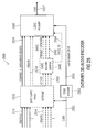
- Fig. 1 shows a block schematic diagram of a multi-channel audio decoder 100, according to an embodiment of the present invention.
- the multi-channel audio decoder 100 is configured to receive an encoded representation 110 and to provide, on the basis thereof, at least two output audio signals 112, 114.
- the multi-channel audio decoder 100 preferably comprises a decoder 120 which is configured to provide decoded audio signals 122 on the basis of the encoded representation 110.
- the multi-channel audio decoder 100 comprises a renderer 130, which is configured to render a plurality of decoded audio signals 122, which are obtained on the basis of the encoded representation 110 (for example, by the decoder 120) in dependence on one or more rendering parameters 132, to obtain a plurality of rendered audio signals 134, 136.
- the multi-channel audio decoder 100 comprises a decorrelator 140, which is configured to derive one or more decorrelated audio signals 142, 144 from the rendered audio signals 134, 136.
- the multi-channel audio decoder 100 comprises a combiner 150, which is configured to combine the rendered audio signals 134, 136, or a scaled version thereof, with the one or more decorrelated audio signals 142, 144 to obtain the output audio signals 112, 114.
- the decorrelated audio signals 142, 144 are derived from the rendered audio signals 134, 136, and that the decorrelated audio signals 142, 144 are combined with the rendered audio signals 134, 136 to obtain the output audio signals 112, 114.
- the decorrelated audio signals 142, 144 are derived from the rendered audio signals 134, 136, and that the decorrelated audio signals 142, 144 are combined with the rendered audio signals 134, 136 to obtain the output audio signals 112, 114.
- applying the decorrelation after the rendering avoids the introduction of artifacts, which could be caused by the renderer when combining multiple decorrelated signals in the case that the decorrelation is applied before the rendering.
- characteristics of the rendered audio signals can be considered in the decorrelation performed by the decorrelator 140, which typically results in output audio signals of good quality.
- multi-channel audio decoder 100 can be supplemented by any of the features and functionalities described herein.
- individual improvements as described herein may be introduced into the multi-channel audio decoder 100 in order to thereby even improve the efficiency of the processing and/or the quality of the output audio signals.
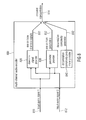
- Fig. 2 shows a block schematic diagram of a multi-channel audio encoder 200, according to an embodiment of the present invention.
- the multi-channel audio encoder 200 is configured to receive two or more input audio signals 210, 212, and to provide, on the basis thereof, an encoded representation 214.
- the multi-channel audio encoder comprises a downmix signal provider 220, which is configured to provide one or more downmix signals 222 on the basis of the at least two input audio signals 210, 212.
- the multi-channel audio encoder 200 comprises a parameter provider 230, which is configured to provide one or more parameters 232 describing a relationship (for example, a cross-correlation, a cross-covariance, a level difference or the like) between the at least two input audio signals 210, 212.
- a parameter provider 230 which is configured to provide one or more parameters 232 describing a relationship (for example, a cross-correlation, a cross-covariance, a level difference or the like) between the at least two input audio signals 210, 212.
- the multi-channel audio encoder 200 also comprises a decorrelation method parameter provider 240, which is configured to provide a decorrelation method parameter 242 describing which decorrelation mode out of a plurality of decorrelation modes should be used at the side of an audio decoder.
- the one or more downmix signals 222, the one or more parameters 232 and the decorrelation method parameter 242 are included, for example, in an encoded form, into the encoded representation 214.
- the hardware structure of the multi-channel audio encoder 200 may be different, as long as the functionalities as described above are fulfilled.
- the distribution of the functionalities of the multi-channel audio encoder 200 to individual blocks should only be considered as an example.
- the one or more downmix signals 222 and the one or more parameters 232 are provided in a conventional way, for example like in an SAOC multi-channel audio encoder or in a USAC multi-channel audio encoder.
- the decorrelation method parameter 242 which is also provided by the multi-channel audio encoder 200 and included into the encoded representation 214, can be used to adapt a decorrelation mode to the input audio signals 210, 212 or to a desired playback quality. Accordingly, the decorrelation mode can be adapted to different types of audio content.
- different decorrelation modes can be chosen for types of audio contents in which the input audio signals 210, 212 are strongly correlated and for types of audio content in which the input audio signals 210, 212 are independent.
- different decorrelation modes can, for example, be signaled by the decorrelation mode parameter 242 for types of audio contents in which a spatial perception is particularly important and for types of audio content in which a spatial impression is less important or even of subordinate importance (for example, when compared to a reproduction of individual channels).
- a multi-channel audio decoder which receives the encoded representation 214, can be controlled by the multi-channel audio encoder 200, and may be set to a decoding mode which brings along a best possible compromise between decoding complexity and reproduction quality.
- multi-channel audio encoder 200 may be supplemented by any of the features and functionalities described herein. It should be noted that the possible additional features and improvements described herein may be added to the multi-channel audio encoder 200 individually or in combination, to thereby improve (or enhance) the multi-channel audio encoder 200.
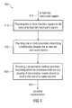
- Fig. 3 shows a flowchart of a method 300 for providing at least two output audio signals on the basis of an encoded representation.
- the method comprises rendering 310 a plurality of decoded audio signals, which are obtained on the basis of an encoded representation 312, in dependence on one or more rendering parameters, to obtain a plurality of rendered audio signals.
- the method 300 also comprises deriving 320 one or more decorrelated audio signals from the rendered audio signals.
- the method 300 also comprises combining 330 the rendered audio signals, or a scaled version thereof, with the one or more decorrelated audio signals, to obtain the output audio signals 332.
- the method 300 is based on the same considerations as the multi-channel audio decoder 100 according to Fig. 1 . Moreover, it should be noted that the method 300 may be supplemented by any of the features and functionalities described herein (either individually or in combination). For example, the method 300 may be supplemented by any of the features and functionalities described with respect to the multi-channel audio decoders described herein.
- Fig. 4 shows a flowchart of a method 400 for providing an encoded representation on the basis of at least two input audio signals.
- the method 400 comprises providing 410 one or more downmix signals on the basis of at least two input audio signals 412.
- the method 400 further comprises providing 420 one or more parameters describing a relationship between the at least two input audio signals 412 and providing 430 a decorrelation method parameter describing which decorrelation mode out of a plurality of decorrelation modes should be used at the side of an audio decoder.
- an encoded representation 432 is provided, which preferably includes an encoded representation of the one or more downmix signals, one or more parameters describing a relationship between the at least two input audio signals, and the decorrelation method parameter.
- the method 400 is based on the same considerations as the multi-channel audio encoder 200 according to Fig. 2 , such that the above explanations also apply.
- the order of the steps 410, 420, 430 can be varied flexibly, and that the steps 410, 420, 430 may also be performed in parallel as far as this is possible in an execution environment for the method 400.
- the method 400 can be supplemented by any of the features and functionalities described herein, either individually or in combination.
- the method 400 may be supplemented by any of the features and functionalities described herein with respect to the multi-channel audio encoders.
- Fig. 5 shows a schematic representation of an encoded audio representation 500 according to an embodiment of the present invention.
- the encoded audio representation 500 comprises an encoded representation 510 of a downmix signal, an encoded representation 520 of one or more parameters describing a relationship between at least two audio signals. Moreover, the encoded audio representation 500 also comprises an encoded decorrelation method parameter 530 describing which decorrelation mode out of a plurality of decorrelation modes should be used at the side of an audio decoder. Accordingly, the encoded audio representation allows to signal a decorrelation mode from an audio encoder to an audio decoder.
- the encoded audio representation 500 allows for a rendering of an audio content represented by the encoded audio representation 500 with a particularly good auditory spatial impression and/or a particularly good tradeoff between auditory spatial impression and decoding complexity.
- encoded representation 500 may be supplemented by any of the features and functionalities described with respect to the multi-channel audio encoders and the multi-channel audio decoders, either individually or in combination.
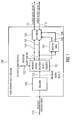
- Fig. 6 shows a block schematic diagram of a multi-channel decorrelator 600, according to an embodiment of the present invention.
- the multi-channel decorrelator 600 is configured to receive a first set of N decorrelator input signals 610a to 610n and provide, on the basis thereof, a second set of N' decorrelator output signals 612a to 612n'.
- the multi-channel decorrelator 600 is configured for providing a plurality of (at least approximately) decorrelated signals 612a to 612n' on the basis of the decorrelator input signals 610a to 610n.
- the multi-channel decorrelator 600 comprises a premixer 620, which is configured to premix the first set of N decorrelator input signals 610a to 610n into a second set of K decorrelator input signals 622a to 622k, wherein K is smaller than N (with K and N being integers).
- the multi-channel decorrelator 600 also comprises a decorrelation (or decorrelator core) 630, which is configured to provide a first set of K' decorrelator output signals 632a to 632k' on the basis of the second set of K decorrelator input signals 622a to 622k.
- the multi-channel decorrelator comprises an postmixer 640, which is configured to upmix the first set of K' decorrelator output signals 632a to 632k' into a second set of N' decorrelator output signals 612a to 612n', wherein N' is larger than K' (with N' and K' being integers).
- the given structure of the multi-channel decorrelator 600 should be considered as an example only, and that it is not necessary to subdivide the multi-channel decorrelator 600 into functional blocks (for example, into the premixer 620, the decorrelation or decorrelator core 630 and the postmixer 640) as long as the functionality described herein is provided.
- the concept of performing a premixing, to derive the second set of K decorrelator input signals from the first set of N decorrelator input signals, and of performing the decorrelation on the basis of the (premixed or "downmixed") second set of K decorrelator input signals brings along a reduction of a complexity when compared to a concept in which the actual decorrelation is applied, for example, directly to N decorrelator input signals.
- the second (upmixed) set of N' decorrelator output signals is obtained on the basis of the first (original) set of decorrelator output signals, which are the result of the actual decorrelation, on the basis of an postmixing, which may be performed by the upmixer 640.
- the multi-channel decorrelator 600 effectively (when seen from the outside) receives N decorrelator input signals and provides, on the basis thereof, N' decorrelator output signals, while the actual decorrelator core 630 only operates on a smaller number of signals (namely K downmixed decorrelator input signals 622a to 622k of the second set of K decorrelator input signals).
- the complexity of the multi-channel decorrelator 600 can be substantially reduced, when compared to conventional decorrelators, by performing a downmixing or "premixing" (which may preferably be a linear premixing without any decorrelation functionality) at an input side of the decorrelation (or decorrelator core) 630 and by performing the upmixing or "postmixing" (for example, a linear upmixing without any additional decorrelation functionality) on the basis of the (original) output signals 632a to 632k' of the decorrelation (decorrelator core) 630.
- a downmixing or "premixing” which may preferably be a linear premixing without any decorrelation functionality
- postmixing for example, a linear upmixing without any additional decorrelation functionality
- multi-channel decorrelator 600 can be supplemented by any of the features and functionalities described herein with respect to the multi-channel decorrelation and also with respect to the multi-channel audio decoders. It should be noted that the features described herein can be added to the multi-channel decorrelator 600 either individually or in combination, to thereby improve or enhance the multi-channel decorrelator 600.
- Fig. 7 shows a block schematic diagram of a multi-channel audio decoder 700, according to an embodiment of the invention.
- the multi-channel audio decoder 700 is configured to receive an encoded representation 710 and to provide, on the basis of thereof, at least two output signals 712, 714.
- the multi-channel audio decoder 700 comprises a multi-channel decorrelator 720, which may be substantially identical to the multi-channel decorrelator 600 according to Fig. 6 .
- the multi-channel audio decoder 700 may comprise any of the features and functionalities of a multi-channel audio decoder which are known to the man skilled in the art or which are described herein with respect to other multi-channel audio decoders.
- the multi-channel audio decoder 700 comprises a particularly high efficiency when compared to conventional multi-channel audio decoders, since the multi-channel audio decoder 700 uses the high-efficiency multi-channel decorrelator 720.
- Fig. 8 shows a block schematic diagram of a multi-channel audio encoder 800 according to an embodiment of the present invention.
- the multi-channel audio encoder 800 is configured to receive at least two input audio signals 810, 812 and to provide, on the basis thereof, an encoded representation 814 of an audio content represented by the input audio signals 810, 812.
- the multi-channel audio encoder 800 comprises a downmix signal provider 820, which is configured to provide one or more downmix signals 822 on the basis of the at least two input audio signals 810, 812.
- the multi-channel audio encoder 800 also comprises a parameter provider 830 which is configured to provide one or more parameters 832 (for example, cross-correlation parameters or cross-covariance parameters, or inter-object-correlation parameters and/or object level difference parameters) on the basis of the input audio signals 810,812.
- the multi-channel audio encoder 800 comprises a decorrelation complexity parameter provider 840 which is configured to provide a decorrelation complexity parameter 842 describing a complexity of a decorrelation to be used at the side of an audio decoder (which receives the encoded representation 814).
- the one or more downmix signals 822, the one or more parameters 832 and the decorrelation complexity parameter 842 are included into the encoded representation 814, preferably in an encoded form.
- the internal structure of the multi-channel audio encoder 800 should be considered as an example only. Different structures are possible as long as the functionality described herein is achieved.
- the multi-channel encoder provides an encoded representation 814, wherein the one or more downmix signals 822 and the one or more parameters 832 may be similar to, or equal to, downmix signals and parameters provided by conventional audio encoders (like, for example, conventional SAOC audio encoders or USAC audio encoders).
- the multi-channel audio encoder 800 is also configured to provide the decorrelation complexity parameter 842, which allows to determine a decorrelation complexity which is applied at the side of an audio decoder. Accordingly, the decorrelation complexity can be adapted to the audio content which is currently encoded.
- a desired decorrelation complexity which corresponds to an achievable audio quality, in dependence on an encoder-sided knowledge about the characteristics of the input audio signals. For example, if it is found that spatial characteristics are important for an audio signal, a higher decorrelation complexity can be signaled, using the decorrelation complexity parameter 842, when compared to a case in which spatial characteristics are not so important.
- the usage of a high decorrelation complexity can be signaled using the decorrelation complexity parameter 842, if it is found that a passage of the audio content or the entire audio content is such that a high complexity decorrelation is required at a side of an audio decoder for other reasons.
- the multi-channel audio encoder 800 provides for the possibility to control a multi-channel audio decoder, to use a decorrelation complexity which is adapted to signal characteristics or desired playback characteristics which can be set by the multi-channel audio encoder 800.
- the multi-channel audio encoder 800 may be supplemented by any of the features and functionalities described herein regarding a multi-channel audio encoder, either individually or in combination. For example, some or all of the features described herein with respect to multi-channel audio encoders can be added to the multi-channel audio encoder 800. Moreover, the multi-channel audio encoder 800 may be adapted for cooperation with the multi-channel audio decoders described herein.
- Fig. 9 shows a flowchart of a method 900 for providing a plurality of decorrelated signals on the basis of a plurality of decorrelator input signals.
- the method 900 comprises premixing 910 a first set of N decorrelator input signals into a second set of K decorrelator input signals, wherein K is smaller than N.
- the method 900 also comprises providing 920 a first set of K' decorrelator output signals on the basis of the second set of K decorrelator input signals.
- the first set of K' decorrelator output signals may be provided on the basis of the second set of K decorrelator input signals using a decorrelation, which may be performed, for example, using a decorrelator core or using a decorrelation algorithm.
- the method 900 further comprises postmixing 930 the first set of K' decorrelator output signals into a second set to N' decorrelator output signals, wherein N' is larger than K' (with N' and K' being integer numbers). Accordingly, the second set of N' decorrelator output signals, which are the output of the method 900, may be provided on the basis of the first set of N decorrelator input signals, which are the input to the method 900.
- the method 900 is based on the same considerations as the multi-channel decorrelator described above. Moreover, it should be noted that the method 900 may be supplemented by any of the features and functionalities described herein with respect to the multi-channel decorrelator (and also with respect to the multi-channel audio encoder, if applicable), either individually or taken in combination.
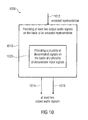
- Fig. 10 shows a flowchart of a method 1000 for providing at least two output audio signals on the basis of an encoded representation.
- the method 1000 comprises providing 1010 at least two output audio signals 1014, 1016 on the basis of an encoded representation 1012.
- the method 1000 comprises providing 1020 a plurality of decorrelated signals on the basis of a plurality of decorrelator input signals in accordance with the method 900 according to Fig. 9 .
- the method 1000 is based on the same considerations as the multi-channel audio decoder 700 according to Fig. 7 .
- the method 1000 can be supplemented by any of the features and functionalities described herein with respect to the multi-channel decoders, either individually or in combination.
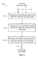
- Fig. 11 shows a flowchart of a method 1100 for providing an encoded representation on the basis of at least two input audio signals.
- the method 1100 comprises providing 1110 one or more downmix signals on the basis of the at least two input audio signals 1112, 1114.
- the method 1100 also comprises providing 1120 one or more parameters describing a relationship between the at least two input audio signals 1112, 1114.
- the method 1100 comprises providing 1130 a decorrelation complexity parameter describing a complexity of a decorrelation to be used at the side of an audio decoder.
- an encoded representation 1132 is provided on the basis of the at least two input audio signals 1112, 1114, wherein the encoded representation typically comprises the one or more downmix signals, the one or more parameters describing a relationship between the at least two input audio signals and the decorrelation complexity parameter in an encoded form.
- the steps 1110, 1120, 1130 may be performed in parallel or in a different order in some embodiments according to the invention.
- the method 1100 is based on the same considerations as the multi-channel audio encoder 800 according to Fig. 8 , and that the method 1100 can be supplemented by any of the features and functionalities described herein with respect to the multi-channel audio encoder, either in combination or individually.
- the method 1100 can be adapted to match the multi-channel audio decoder and the method for providing at least two output audio signals described herein.
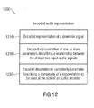
- Fig. 12 shows a schematic representation of an encoded audio representation, according to an embodiment of the present invention.
- the encoded audio representation 1200 comprises an encoded representation 1210 of a downmix signal, an encoded representation 1220 of one or more parameters describing a relationship between the at least two input audio signals, and an encoded decorrelation complexity parameter 1230 describing a complexity of a decorrelation to be used at the side of an audio decoder. Accordingly, the encoded audio representation 1200 allows to adjust the decorrelation complexity used by a multi-channel audio decoder, which brings along an improved decoding efficiency, and possible an improved audio quality, or an improved tradeoff between coding efficiency and audio quality.
- the encoded audio representation 1200 may be provided by the multi-channel audio encoder as described herein, and may be used by the multi-channel audio decoder as described herein. Accordingly, the encoded audio representation 1200 can be supplemented by any of the features described with respect to the multi-channel audio encoders and with respect to the multi-channel audio decoders.
- General parametric separation systems aim to estimate a number of audio sources from a signal mixture (downmix) using auxiliary parameter information (like, for example, inter-channel correlation values, inter-channel level difference values, inter-object correlation values and/or object level difference information).
- auxiliary parameter information like, for example, inter-channel correlation values, inter-channel level difference values, inter-object correlation values and/or object level difference information.
- MMSE minimum mean squared error
- Fig. 13 shows the general principle of the SAOC encoder/decoder architecture.
- Fig. 13 shows, in the form of a block schematic diagram, an overview of the MMSE based parametric downmix/upmix concept.
- An encoder 1310 receives a plurality of object signals 1312a, 1312b to 1312n. Moreover, the encoder 1310 also receives mixing parameters D, 1314, which may, for example, be downmix parameters. The encoder 1310 provides, on the basis thereof, one or more downmix signals 1316a, 1316b, and so on. Moreover, the encoder provides a side information 1318 The one or more downmix signals and the side information may, for example, be provided in an encoded form.
- the encoder 1310 comprises a mixer 1320, which is typically configured to receive the object signals 1312a to 1312n and to combine (for example downmix) the object signals 1312a to 1312n into the one or more downmix signals 1316a, 1316b in dependence on the mixing parameters 1314.
- the encoder comprises a side information estimator 1330, which is configured to derive the side information 1318 from the object signals 1312a to 1312n.
- the side information estimator 1330 may be configured to derive the side information 1318 such that the side information describes a relationship between object signals, for example, a cross-correlation between object signals (which may be designated as "inter-object-correlation” IOC) and/or an information describing level differences between object signals (which may be designated as a "object level difference information" OLD).
- IOC cross-correlation between object signals
- OLD information describing level differences between object signals
- the one or more downmix signals 1316a, 1316b and the side information 1318 may be stored and/or transmitted to a decoder 1350, which is indicated at reference numeral 1340.
- the decoder 1350 receives the one or more downmix signals 1316a, 1316b and the side information 1318 (for example, in an encoded form) and provides, on the basis thereof, a plurality of output audio signals 1352a to 1352n.
- the decoder 1350 may also receive a user interaction information 1354, which may comprise one or more rendering parameters R (which may define a rendering matrix).
- the decoder 1350 comprises a parametric object separator 1360, a side information processor 1370 and a renderer 1380.
- the side information processor 1370 receives the side information 1318 and provides, on the basis thereof, a control information 1372 for the parametric object separator 1360.
- the parametric object separator 1360 provides a plurality of object signals 1362a to 1362n on the basis of the downmix signals 1360a, 1360b and the control information 1372, which is derived from the side information 1318 by the side information processor 1370.
- the object separator may perform a decoding of the encoded downmix signals and an object separation.
- the renderer 1380 renders the reconstructed object signals 1362a to 1362n, to thereby obtain the output audio signals 1352a to 1352n.
- the general parametric downmix/upmix processing is carried out in a time/frequency selective way and can be described as a sequence of the following steps:
- Fig. 14 shows a geometric representation for orthogonality principle in 3-dimensional space.
- a vector space is spanned by vectors y 1 , y 2 .
- a vector x is equal to a sum of a vector x ⁇ and a difference vector (or error vector) e.
- the error vector e is orthogonal to the vector space (or plane) V spanned by vectors y 1 and y 2 . Accordingly, vector x ⁇ can be considered as a best approximation of x within the vector space V .
- a matrix comprising N signals: X and denoting the estimation error with X Error .
- the MMSE-based algorithms introduce reconstruction inaccuracy X Error ⁇ X Error H .
- the cross-covariance (coherence/correlation) is closely related to the perception of envelopment, of being surrounded by the sound, and to the perceived width of a sound source.
- IOC Inter-Object Correlation
- the output signal may exhibit a lower energy compared to the original objects.
- the error in the diagonal elements of the covariance matrix may result in audible level differences and error in the off-diagonal elements in a distorted spatial sound image (compared with the ideal reference output).
- the proposed method has the purpose to solve this problem.
- MPS MPEG Surround
- this issue is treated only for some specific channel-based processing scenarios, namely, for mono/stereo downmix and limited static output configurations (e.g., mono, stereo, 5.1, 7.1, etc).
- object-oriented technologies like SAOC, which also uses mono/stereo downmix this problem is treated by applying the MPS post-processing rendering for 5.1 output configuration only.
- Embodiments according to the invention extend the MMSE parametric reconstruction methods used in parametric audio separation schemes with a decorrelation solution for an arbitrary number of downmix/upmix channels.
- Embodiments according to the invention may compensate for the energy loss during a parametric reconstruction and restore the correlation properties of estimated objects.
- Fig. 15 provides an overview of the parametric downmix/upmix concept with an integrated decorrelation path.
- Fig. 15 shows, in the form of a block schematic diagram, a parametric reconstruction system with decorrelation applied on rendered output.
- the system according to Fig. 15 comprises an encoder 1510, which is substantially identical to the encoder 1310 according to Fig. 13 .
- the encoder 1510 receives a plurality of object signals 1512a to 1512n, and provides on the basis thereof, one or more downmix signals 1516a, 1516b, as well as a side information 1518.
- Downmix signals 1516a, 1515b may be substantially identical to the downmix signals 1316a, 1316b and may designated with Y.
- the side information 1518 may be substantially identical to the side information 1318. However, the side information may, for example, comprise a decorrelation mode parameter or a decorrelation method parameter, or a decorrelation complexity parameter.
- the encoder 1510 may receive mixing parameters 1514.
- the parametric reconstruction system also comprises a transmission and/or storage of the one or more downmix signals 1516a, 1516b and of the side information 1518, wherein the transmission and/or storage is designated with 1540, and wherein the one or more downmix signals 1516a, 1516b and the side information 1518 (which may include parametric side information) may be encoded.
- the parametric reconstruction system comprises a decoder 1550, which is configured to receive the transmitted or stored one or more (possibly encoded) downmix signals 1516a, 1516b and the transmitted or stored (possibly encoded) side information 1518 and to provide, on the basis thereof, output audio signals 1552a to 1552n.
- the decoder 1550 (which may be considered as a multi-channel audio decoder) comprises a parametric object separator 1560 and a side information processor 1570.
- the decoder 1550 comprises a renderer 1580, a decorrelator 1590 and a mixer 1598.
- the parametric object separator 1560 is configured to receive the one or more downmix signals 1516a, 1516b and a control information 1572, which is provided by the side information processor 1570 on the basis of the side information 1518, and to provide, on the basis thereof, object signals 1562a to 1562n, which are also designated with X ⁇ , and which may be considered as decoded audio signals.
- the control information 1572 may, for example, comprise un-mixing coefficients to be applied to downmix signals (for example, to decoded downmix signals derived from the encoded downmix signals 1516a, 1516b) within the parametric object separator to obtain reconstructed object signals (for example, the decoded audio signals 1562a to 1562n).
- the renderer 1580 renders the decoded audio signals 1562a to 1562n (which may be reconstructed object signals, and which may, for example, correspond to the input object signals 1512a to 1512n), to thereby obtain a plurality of rendered audio signals 1582a to 1582n.
- the renderer 1580 may consider rendering parameters R , which may for example be provided by user interaction and which may, for example, define a rendering matrix.
- the rendering parameters may be taken from the encoded representation (which may include the encoded downmix signals 1516a, 1516b and the encoded side information 1518).
- the decorrelator 1590 is configured to receive the rendered audio signals 1582a to 1582n and to provide, on the basis thereof, decorrelated audio signals 1592a to 1592n, which are also designated with W .
- the mixer 1598 receives the rendered audio signals 1582a to 1582n and the decorrelated audio signals 1592a to 1592n, and combines the rendered audio signals 1582a to 1582n and the decorrelated audio signals 1592a to 1592n, to thereby obtain the output audio signals 1552a to 1552n.
- the mixer 1598 may also use control information 1574 which is derived by the side information processor 1570 from the encoded side information 1518, as will be described below.
- the output signal w has equal (to the input signal ⁇ ) spectral and temporal envelope properties (or at least similar properties).
- signal w is perceived similarly and has the same (or similar) subjective quality as the input signal ⁇ (see, for example, [SAOC2]).
- the decorrelator output W can be used to compensate for prediction inaccuracy in an MMSE estimator (remembering that the prediction error is orthogonal to the predicted signals) by using the predicted signals as the inputs.
- one aim of the inventive concept is to create a mixture of the "dry” (i.e., decorrelator input) signal (e.g., rendered audio signals 1582a to 1582n) and "wet” (i.e., decorrelator output) signal (e.g., decorrelated audio signals 1592a to 1592n), such that the covariance matrix of the resulting mixture (e.g. output audio signals 1552a to 1552n) becomes similar to the covariance matrix of the desired output.
- dry i.e., decorrelator input
- wet i.e., decorrelator output signal
- the proposed method for the output covariance error correction composes the output signal Z ⁇ (e.g. the output audio signals 1552a to 1552n) as a weighted sum of parametrically reconstructed signal ⁇ (e.g., the rendered audio signals 1582a to 1582n) and its decorrelated part W .
- E Z ⁇ FE S ⁇ F H .
- the mixing matrix F is computed such that the covariance matrix E Z ⁇ of the final output approximates, or equals, the target covariance C as E Z ⁇ ⁇ C .
- S Singular Value Decomposition
- the prototype matrix H can be chosen according to the desired weightings for the direct and decorrelated signal paths.
- Singular Value Decomposition Singular Value Decomposition
- C FE S ⁇ F H
- UTU H FVQV H ⁇ F H
- U ⁇ T ⁇ U H ⁇ U ⁇ T ⁇ U ⁇ H F V ⁇ Q ⁇ V H ⁇ V ⁇ Q ⁇ V H ⁇ F H
- U ⁇ T ⁇ U H ⁇ U ⁇ T ⁇ U H FV ⁇ Q ⁇ V H ⁇ V ⁇ Q ⁇ V H ⁇ F H
- U ⁇ T ⁇ U H ⁇ U ⁇ T ⁇ U H FV ⁇ Q ⁇ V H ⁇ V ⁇ Q ⁇ V H ⁇ F H
- U ⁇ T ⁇ U H ⁇ U ⁇ T ⁇ U H H FV ⁇ Q ⁇ V H ⁇ FV ⁇ Q ⁇ V H H H .
- mixing matrix F U ⁇ T ⁇ U H ⁇ H ⁇ V ⁇ Q - 1 ⁇ V H .
- the last equation may need to include some regularization, but otherwise it should be numerically stable.
- a concept has been described to derive the output audio signals (represented by matrix Z ⁇ , or equivalently, by vector z ⁇ ) on the basis of the rendered audio signals (represented by matrix ⁇ , or equivalently, vector ⁇ ) and the decorrelated audio signals (represented by matrix W , or equivalently, vector w ).
- two mixing matrices P and M of general matrix structure are commonly determined.
- a combined matrix F as defined above, may be determined, such that a covariance matrix E ⁇ of the output audio signals 1552a to 1562n approximates, or equals, a desired covariance (also designated as target covariance) C.
- the desired covariance matrix C may, for example, be derived on the basis of the knowledge of the rendering matrix R (which may be provided by user interaction, for example) and on the basis of a knowledge of the object covariance matrix E X , which may for example be derived on the basis of the encoded side information 1518.
- the object covariance matrix E X may be derived using the inter-object correlation values IOC, which are described above, and which may be included in the encoded side information 1518.
- the target covariance matrix C may, for example, be provided by the side information processor 1570 as the information 1574, or as part of the information 1574.
- the side information processor 1570 may also directly provide the mixing matrix F as the information 1574 to the mixer 1598.
- the entries a i , i and b i , i of the prototype matrix H may be chosen.
- the entries of the prototype matrix H are chosen to be somewhere between 0 and 1. If values a i,i are chosen to be closer to one, there will be a significant mixing of rendered output audio signals, while the impact of the decorrelated audio signals is comparatively small, which may be desirable in some situations. However, in some other situations it may be more desirable to have a comparatively large impact of the decorrelated audio signals, while there is only a weak mixing between rendered audio signals. In this case, values b i , i are typically chosen to be larger than a i , i .
- the decoder 1550 can be adapted to the requirements by appropriately choosing the entries of the prototype matrix H .
- the signal ⁇ e.g., the rendered audio signals 1582a to 1582n
- the parametric reconstructions ⁇ e.g., the output audio signals 1552a to 1552n
- the mixing matrix P can be reduced to an identity matrix (or a multiple thereof).
- ⁇ E C - E Z ⁇ .
- mixing matrix M is determined such that ⁇ E ⁇ ME W ⁇ M H .
- Singular Value Decomposition Singular Value Decomposition
- This approach ensures good cross-correlation reconstruction maximizing use of the dry output (e.g., of the rendered audio signals 1582a to 1582n) and utilizes freedom of mixing of decorrelated signals only.
- the dry output e.g., of the rendered audio signals 1582a to 1582n
- a given decorrelated signal is combined, with a same or different scaling, with a plurality of rendered audio signals, or a scaled version thereof, in order to adjust cross-correlation characteristics or cross-covariance characteristics of the output audio signals.
- the combination is defined, for example, by the matrix M as defined here.
- Singular Value Decomposition SVD
- mixing matrix M U ⁇ T ⁇ U H ⁇ V ⁇ Q - 1 ⁇ V H .
- the last equation may need to include some regularization, but otherwise it should be numerically stable.
- the main goal of this approach is to use decorrelated signals to compensate for the loss of energy in the parametric reconstruction (e.g., rendered audio signal), while the off-diagonal modification of the covariance matrix of the output signal is ignored, i.e., there is no direct handling of the cross-correlations. Therefore, no cross-leakage between the output objects/channels (e.g., between the rendered audio signals) is introduced in the application of the decorrelated signals.
- the parametric reconstruction e.g., rendered audio signal
- the energies can be reconstructed parametrically (for example, using OLDs, IOCs and rendering coefficients) or may be actually computed by the decoder (which is typically more computationally expensive).
- This method maximizes the use of the dry rendered outputs explicitly.
- the method is equivalent with the simplification "A" when the covariance matrices have no off-diagonal entries.
- This method has a reduced computational complexity.
- the energy compensation method doesn't necessarily imply that the cross-correlation terms are not modified. This holds only if we use ideal decorrelators and no complexity reduction for the decorrelation unit.
- the idea of the method is to recover the energy and ignore the modifications in the cross terms (the changes in the cross-terms will not modify substantially the correlation properties and will not affect the overall spatial impression).
- any method for compensating for the parametric reconstruction errors should produce a result with the following property: if the rendering matrix equals the downmix matrix then the output channels should equal (or at least approximate) the downmix channels.
- E S E Z ⁇ E Z ⁇ ⁇ W H E Z ⁇ ⁇ W E W , where the matrix E ⁇ W is cross-covariance between the direct ⁇ and decorrelated W signals.
- E W M post matdiag M pre ⁇ E Z ⁇ ⁇ M pre H ⁇ M post H .
- decorrelator function implementation is often computationally complex. In some applications (e.g., portable decoder solutions) limitations on the number of decorrelators may need to be introduced due to the restricted computational resources.
- This section provides a description of means for reduction of decorrelator unit complexity by controlling the number of applied decorrelators (or decorrelations).
- the decorrelation unit interface is depicted in Figs. 16 and 17 .
- Fig. 16 shows a block schematic diagram of a simple (conventional) decorrelation unit.
- the decorrelation unit 1600 according to Fig. 6 is configured to receive N decorrelator input signals 1610a to 1610n, like for example rendered audio signals ⁇ .
- the decorrelation unit 1600 provides N decorrelator output signals 1612a to 1612n.
- the decorrelation unit 1600 may, for example, comprise N individual decorrelators (or decorrelation functions) 1620a to 1620n.
- each of the individual decorrelators 1620a to 1620n may provide one of the decorrelator output signals 1612a to 1612n on the basis of an associated one of the decorrelator input signals 1610a to 1610n.
- N individual decorrelators, or decorrelation functions, 1620a to 1620n may be required to provide the N decorrelated signals 1612a to 1612n on the basis of the N decorrelator input signals 1610a to 1610n.
- Fig. 17 shows a block schematic diagram of a reduced complexity decorrelation unit 1700.
- the reduced complexity decorrelation unit 1700 is configured to receive N decorrelator input signals 1710a to 1710n and to provide, on the basis thereof, N decorrelator output signals 1712a to 1712n.
- the decorrelator input signals 1710a to 1710n may be rendered audio signals ⁇
- the decorrelator output signals 1712a to 1712n may be decorrelated audio signals W .
- the decorrelator 1700 comprises a premixer (or equivalently, a premixing functionality) 1720 which is configured to receive the first set of N decorrelator input signals 1710a to 1710n and to provide, on the basis thereof, a second set of K decorrelator input signals 1722a to 1722k.
- the premixer 1720 may perform a so-called "premixing” or "downmixing" to derive the second set of K decorrelator input signals 1722a to 1722k on the basis of the first set of N decorrelator input signals 1710a to 1710n.
- the K signals of the second set of K decorrelator input signals 1722a to 1722k may be represented using a matrix ⁇ mix .
- the decorrelation unit (or, equivalently, multi-channel decorrelator) 1700 also comprises a decorrelator core 1730, which is configured to receive the K signals of the second set of decorrelator input signals 1722a to 1722k, and to provide, on the basis thereof, K decorrelator output signals which constitute a first set of decorrelator output signals 1732a to 1732k.
- the decorrelator core 1730 may comprise K individual decorrelators (or decorrelation functions), wherein each of the individual decorrelators (or decorrelation functions) provides one of the decorrelator output signals of the first set of K decorrelator output signals 1732a to 1732k on the basis of a corresponding decorrelator input signal of the second set of K decorrelator input signals 1722a to 1722k.
- a given decorrelator, or decorrelation function may be applied K times, such that each of the decorrelator output signals of the first set of K decorrelator output signals 1732a to 1732k is based on a single one of the decorrelator input signals of the second set of K decorrelator input signals 1722a to 1722k.
- the decorrelation unit 1700 also comprises a postmixer 1740, which is configured to receive the K decorrelator output signals 1732a to 1732k of the first set of decorrelator output signals and to provide, on the basis thereof, the N signals 1712a to 1712n of the second set of decorrelator output signals (which constitute the "external" decorrelator output signals).
- the premixer 1720 may preferably perform a linear mixing operation, which may be described by a premixing matrix M pre .
- the postmixer 1740 preferably performs a linear mixing (or upmixing) operation, which may be represented by a postmixing matrix M post , to derive the N decorrelator output signals 1712a to 1712n of the second set of decorrelator output signals from the first set of K decorrelator output signals 1732a to 1732k (i.e., from the output signals of the decorrelator core 1730).
- the main idea of the proposed method and apparatus is to reduce the number of input signals to the decorrelators (or to the decorrelator core) from N to K by:
- the premixing matrix M pre can be constructed based on the downmix/rendering/correlation/etc information such that the matrix product M pre ⁇ M pre H becomes well-conditioned (with respect to inversion operation).
- the postmixing matrix can be computed as M post ⁇ M pre H ⁇ M pre ⁇ M pre H - 1 .
- K The number of used decorrelators (or individual decorrelations), K , is not specified and is dependent on the desired computational complexity and available decorrelators. Its value can be varied from N (highest computational complexity) down to 1 (lowest computational complexity).
- the number of input signals to the decorrelator unit, N is arbitrary and the proposed method supports any number of input signals, independent on the rendering configuration of the system.
- premixing matrix M pre For example in applications using 3D audio content, with high number of output channels, depending on the output configuration one possible expression for the premixing matrix M pre is described below.
- the premixing which is performed by the premixer 1720 (and, consequently, the postmixing, which is performed by the postmixer 1740) is adjusted if the decorrelation unit 1700 is used in a multi-channel audio decoder, wherein the decorrelator input signals 1710a to 1710n of the first set of decorrelator input signals are associated with different spatial positions of an audio scene.
- Fig. 18 shows a table representation of loudspeaker positions, which are used for different output formats.
- a first column 1810 describes a loudspeaker index number.
- a second column 1820 describes a loudspeaker label.
- a third column 1830 describes an azimuth position of the respective loudspeaker, and a fourth column 1832 describes an azimuth tolerance of the position of the loudspeaker.
- a fifth column 1840 describes an elevation of a position of the respective loudspeaker, and a sixth column 1842 describes a corresponding elevation tolerance.
- a seventh column 1850 indicates which loudspeakers are used for the output format O-2.0.
- An eighth column 1860 shows which loudspeakers are used for the output format O-5.1.
- a ninth column 1864 shows which loudspeakers are used for the output format O-7.1.
- a tenth column 1870 shows which loudspeakers are used for the output format O-8.1
- an eleventh column 1880 shows which loudspeakers are used for the output format O-10.1
- a twelfth column 1890 shows which loudspeakers are used for the output formal O-22.2.
- two loudspeakers are used for output format O-2.0
- six loudspeakers are used for output format O-5.1
- eight loudspeakers are used for output format O-7.1
- nine loudspeakers are used for output format O-8.1
- 11 loudspeakers are used for output format O-10.1
- 24 loudspeaker are used for output format O-22.2.
- one low frequency effect loudspeaker is used for output formats O-5.1, O-7.1, O-8.1 and O-10.1, and that two low frequency effect loudspeakers (LFE1, LFE2) are used for output format O-22.2.
- LFE1, LFE2 two low frequency effect loudspeakers
- one rendered audio signal is associated with each of the loudspeakers, except for the one or more low frequency effect loudspeakers.
- two rendered audio signals are associated with the two loudspeakers used according to the O-2.0 format
- five rendered audio signals are associated with the five non-low-frequency-effect loudspeakers if the O-5.1 format is used
- seven rendered audio signals are associated with seven non-low-frequency-effect loudspeakers if the O-7.1 format is used
- eight rendered audio signals are associated with the eight non-low-frequency-effect loudspeakers if the O-8.1 format is used
- ten rendered audio signals are associated with the ten non-low-frequency-effect loudspeakers if the O-10.1 format is used
- 22 rendered audio signals are associated with the 22 non-low-frequency-effect loudspeakers if the O-22.2 format is used.
- Fig. 19a shows a table representation of entries of a premixing matrix M pre .
- the rows, labeled with 1 to 11 in Fig. 19a represent the rows of the premixing matrix M pre
- the columns, labeled with 1 to 22 are associated with columns of the premixing matrix M pre .
- each row of the premixing matrix M pre is associated with one of the K decorrelator input signals 1722a to 1722k of the second set of decorrelator input signals (i.e., with the input signals of the decorrelator core).
- each column of the premixing matrix M pre is associated with one of the N decorrelator input signals 1710a to 1710n of the first set of decorrelator input signals, and consequently with one of the rendered audio signals 1582a to 1582n (since the decorrelator input signals 1710a to 1710n of the first set of decorrelator input signals are typically identical to the rendered audio signals 1582 to 1582n in an embodiment).
- each column of the premixing matrix M pre is associated with a specific loudspeaker and, consequently, since loudspeakers are associate with spatial positions, with a specific spatial position.
- a row 1910 indicates to which loudspeaker (and, consequently, to which spatial position) the columns of the premixing matrix M pre are associated (wherein the loudspeaker labels are defined in the column 1820 of the table 1800).
- a second downmixed decorrelator input signal i.e., a second decorrelator input signal of the second set of decorrelator input signals.
- the premixing matrix M pre of Fig. 19a defines eleven combinations of two rendered audio signals each, such that eleven downmixed decorrelator input signals are derived from 22 rendered audio signals. It can also be seen that four center signals are combined, to obtain two downmixed decorrelator input signals (confer columns 1 to 4 and rows 1 and 2 of the premixing matrix).
- the other downmixed decorrelator input signals are each obtained by combining two audio signals associated with the same side of the audio scene.
- a third downmixed decorrelator input signal represented by the third row of the premixing matrix, is obtained by combining rendered audio signals associated with an azimuth position of +135° ("CH_M_L135"; "CH_U_L135").
- a fourth decorrelator input signal (represented by a fourth row of the premix matrix) is obtained by combining rendered audio signals associated with an azimuth position of - 135° ("CH_M_R135"; "CH_U_R135").
- each of the downmixed decorrelator input signals is obtained by combining two rendered audio signals associated with same (or similar) azimuth position (or, equivalently, horizontal position), wherein there is typically a combination of signals associated with different elevation (or, equivalently, vertical position).
- the structure of the table of Fig. 19b is identical to the structure of the table of Fig. 19a .
- the premixing matrix M pre according to Fig. 19b differs from the premixing matrix M pre of Fig. 19a in that the first row describes the combination of four rendered audio signals having channel IDs (or positions) "CH_M-000", “CH_L_000”, “CH_U_000” and "CH_T_000".
- four rendered audio signals associated with vertically adjacent positions are combined in the premixing in order to reduce the number of required decorrelators (ten decorrelators instead of eleven decorrelators for the matrix according to Fig. 19a ).
- rendered audio signals having channel IDs "CH_M_L135" and “CH_U_L135" are associated with identical horizontal positions (or azimuth positions) on the same side of the audio scene and spatially adjacent vertical positions (or elevations), and that the rendered audio signals having channel IDs "CH_M_R135" and “CH_U_R135" are associated with identical horizontal positions (or azimuth positions) on a second side of the audio scene and spatially adjacent vertical positions (or elevations).
- the rendered audio signals having channel IDs "CH_M_L135", "CH_U_L135", “CH_M_R135" and “CH_U_R135" are associated with a horizontal pair (or even a horizontal quadruple) of spatial positions comprising a left side position and a right side position.
- a horizontal pair or even a horizontal quadruple of spatial positions comprising a left side position and a right side position.
- Figs. 19d , 19e , 19f and 19g it can be seen that more and more rendered audio signals are combined with decreasing number of (individual) decorrelators (i.e. with decreasing K).
- Figs. 19a to 19g typically rendered audio signals which are downmixed into two separate downmixed decorrelator input signals are combined when decreasing the number of decorrelators by 1.
- rendered audio signals are combined, which are associated with a "symmetrical quadruple" of spatial positions, wherein, for a comparatively high number of decorrelators, only rendered audio signals associated with equal or at least similar horizontal positions (or azimuth positions) are combined, while for comparatively lower number of decorrelators, rendered audio signals associated with spatial positions on opposite sides of the audio scene are also combined.
- the premixing matrices according to Figs. 19 to 23 can be used, for example, in a switchable manner, in a multi-channel decorrelator which is part of a multi-channel audio decoder.
- the switching between the premixing matrices can be performed, for example, in dependence on a desired output configuration (which typically determines a number N of rendered audio signals) and also in dependence on a desired complexity of the decorrelation (which determines the parameter K, and which may be adjusted, for example, in dependence on a complexity information included in an encoded representation of an audio content).
- Fig. 24 shows, in the form of a table, a grouping of loudspeaker positions, which may be associated with rendered audio signals.
- a first row 2410 describes a first group of loudspeaker positions, which are in a center of an audio scene.
- a second row 2412 represents a second group of loudspeaker positions, which are spatially related.
- Loudspeaker positions "CH_M_L135" and “CH_U_L135" are associated with identical azimuth positions (or equivalently horizontal positions) and adjacent elevation positions (or equivalently, vertically adjacent positions).
- positions "CH_M_R135" and “CH_U_R135" comprise identical azimuth (or, equivalently, identical horizontal position) and similar elevation (or, equivalently, vertically adjacent position).
- positions "CH_M_L135", “CH_U_L135", “CH_M_R135" and “CH_U_R135" form a quadruple of positions, wherein positions “CH_M_L135" and “CH_U_L135" are symmetrical to positions “CH_M_R135" and "CH_U_R135" with respect to a center plane of the audio scene.
- positions “CH_M_180” and “CH_U_180” also comprise identical azimuth position (or, equivalently, identical horizontal position) and similar elevation (or, equivalently, adjacent vertical position).
- a third row 2414 represents a third group of positions. It should be noted that positions “CH_M_L030” and “CH_L_L045" are spatially adjacent positions and comprise similar azimuth (or, equivalently, similar horizontal position) and similar elevation (or, equivalently, similar vertical position). The same holds for positions “CH_M_R030” and “CH_L_R045". Moreover, the positions of the third group of positions form a quadruple of positions, wherein positions “CH_M_L030” and “CH_L_L045" are spatially adjacent, and symmetrical with respect to a center plane of the audio scene, to positions “CH_M_R030" and "CH_L_R045".
- a fourth row 2416 represents four additional positions, which have similar characteristics when compared to the first four positions of the second row, and which form a symmetrical quadruple of positions.
- a fifth row 2418 represents another quadruple of symmetrical positions "CH_M_L060", “CH_U_L045", “CH_M_R060” and “CH_U_R045".
- rendered audio signals associated with the positions of the different groups of positions may be combined more and more with decreasing number of decorrelators.
- rendered audio signals associated with positions in the first and second column may be combined for each group.
- rendered audio signals associated with the positions represented in a third and a fourth column may be combined for each group.
- rendered audio signals associated with the positions shown in the fifth and sixth column may be combined for the second group. Accordingly, eleven downmix decorrelator input signals (which are input into the individual decorrelators) may be obtained.
- rendered audio signals associated with the positions shown in columns 1 to 4 may be combined for one or more of the groups. Also, rendered audio signals associated with all positions of the second group may be combined, if it is desired to further reduce a number of individual decorrelators.
- the signals fed to the output layout have horizontal and vertical dependencies, that should be preserved during the decorrelation process. Therefore, the mixing coefficients are computed such that the channels corresponding to different loudspeaker groups are not mixed together.
- each group first are mixed together the vertical pairs (between the middle layer and the upper layer or between the middle layer and the lower layer). Second, the horizontal pairs (between left and right) or remaining vertical pairs are mixed together. For example, in group three, first the channels in the left vertical pair ("CH_M_L030" and "CH_L_L045"), and in the right vertical pair (“CH_M_R030" and "CH_L_R045"), are mixed together, reducing in this way the number of required decorrelators for this group from four to two. If it is desired to reduce even more the number of decorrelators, the obtained horizontal pair is downmixed to only one channel, and the number of required decorrelators for this group is reduced from four to one.
- the tables mentioned above are derived for different levels of desired decorrelation (or for different levels of desired decorrelation complexity).
- the SAOC internal renderer will pre-render to an intermediate configuration (e.g., the configuration with the highest number of loudspeakers).
- an information about which of the output audio signals are mixed together in an external renderer or format converter are used to determine the premixing matrix M pre , such that the premixing matrix defines a combination of such decorrelator input signals (of the first set of decorrelator input signals) which are actually combined in the external renderer.
- information received from the external renderer/format converter (which receives the output audio signals of the multi-channel decoder) is used to select or adjust the premixing matrix (for example, when the internal rendering matrix of the multi-channel audio decoder is set to identity, or initialized with the mixing coefficients derived from an intermediate rendering configuration), and the external renderer/format converter is connected to receive the output audio signals as mentioned above with respect to the multi-channel audio decoder.
- the decorrelation method may be signaled into the bitstream for ensuring a desired quality level.
- the user or an audio encoder
- the MPEG SAOC bitstream syntax can be, for example, extended with two bits for specifying the used decorrelation method and/or two bits for specifying the configuration (or complexity).
- Fig. 25 shows a syntax representation of bitstream elements "bsDecorrelationMethod” and "bsDecorrelationLevel", which may be added, for example, to a bitstream portion "SAOCSpecifigConfig()" or "SAOC3DSpecificConfig()".
- bitstream element "bsDecorrelationMethod” two bits may be used for the bitstream element "bsDecorrelationLevel"
- Fig. 26 shows, in the form of a table, an association between values of the bitstream variable "bsDecorrelationMethod" and the different decorrelation methods.
- three different decorrelation methods may be signaled by different values of said bitstream variable.
- an output covariance correction using decorrelated signals as described, for example, in section 14.3, may be signaled as one of the options.
- a covariance adjustment method for example, as described in section 14.4.1 may be signaled.
- an energy compensation method for example, as described in section 14.4.2 may be signaled. Accordingly, three different methods for the reconstruction of signal characteristics of the output audio signals on the basis of the rendered audio signals and the decorrelated audio signals can be selected in dependence on a bitstream variable.
- Energy compensation mode uses the method described in section 14.4.2
- limited covariance adjustment mode uses the method described in section 14.4.1
- general covariance adjustment mode uses the method described in section 14.3.
- Fig. 27 which shows, in the form of a table representation, how different decorrelation levels can be signaled by the bitstream variable "bsDecorrelationLevel", a method for selecting the decorrelation complexity will be described.
- said variable can be evaluated by a multi-channel audio decoder comprising the multi-channel decorrelator described above to decide which decorrelation complexity is used.
- said bitstream parameter may signal different decorrelation "levels" which may be designated with the values: 0, 1, 2 and 3.
- An example of decorrelation configurations (which may, for example, be designated as decorrelation levels”) is given in the table of Fig. 27.
- FIG. 27 shows a table representation of a number of decorrelators for different "levels” (e.g., decorrelation levels) and output configurations.
- Fig. 27 shows the number K of decorrelator input signals (of the second set of decorrelator input signals), which is used by the multi-channel decorrelator.
- a number of (individual) decorrelators used in the multi-channel decorrelator is switched between 11, 9, 7 and 5 for a 22.2 output configuration, in dependence on which "decorrelation level" is signaled by the bitstream parameter "bsDecorrelationLevel".
- a selection is made between 10, 5, 3 and 2 individual decorrelators, for an 8.1 configuration, a selection is made between 8, 4, 3 or 2 individual decorrelators, and for a 7.1 output configuration, a selection is made between 7, 4, 3 and 2 decorrelators in dependence on the "decorrelation level" signaled by said bitstream parameter.
- the 5.1 output configuration there are only three valid options for the numbers of individual decorrelators, namely 5, 3, or 2.
- the 2.1 output configuration there is only a choice between two individual decorrelators (decorrelation level 0) and one individual decorrelator (decorrelation level 1).
- the decorrelation method can be determined at the decoder side based on the computational power and an available number of decorrelators.
- selection of the number of decorrelators may be made at the encoder side and signaled using a bitstream parameter.
- both the method how the decorrelated audio signals are applied, to obtain the output audio signals, and the complexity for the provision of the decorrelated signals can be controlled from the side of an audio encoder using the bitstream parameters shown in Fig. 25 and defined in more detail in Figs. 26 and 27 .
- Embodiments according to the invention improve a reconstruction accuracy of energy and correlation properties and therefore increase perceptual audio quality of the final output signal
- Embodiments according to the invention can be applied for an arbitrary number of downmix/upmix channels.
- the methods and apparatuses described herein can be combined with existing parametric source separation algorithms.
- Embodiments according to the invention allow to control computational complexity of the system by setting restrictions on the number of applied decorrelator functions.
- Embodiments according to the invention can lead to a simplification of the object-based parametric construction algorithms like SAOC by removing an MPS transcoding step.
- a 3D audio codec system in which concepts according to the present invention can be used, is based on an MPEG-D USAC codec for coding of channel and object signals to increase the efficiency for coding a large amount of objects.
- MPEG-SAOC technology has been adapted. Three types of renderers perform the tasks of rendering objects to channels, rendering channels to headphones or rendering channels to different loudspeaker setups.
- object signals are explicitly transmitted or parametrically encoded using SAOC, the corresponding object metadata information is compressed and multiplexed into the 3D audio stream.
- Figs. 28 , 29 und 30 show the different algorithmic blocks of the 3D audio system.
- Fig. 28 shows a block schematic diagram of such an audio encoder
- Fig. 29 shows a block schematic diagram of such an audio decoder.
- Figs. 28 and 29 show the different algorithm blocks of the 3D audio system.
- the encoder 2900 comprises an optional pre-renderer/mixer 2910, which receives one or more channel signals 2912 and one or more object signals 2914 and provides, on the basis thereof, one or more channel signals 2916 as well as one or more object signals 2918, 2920.
- the audio encoder also comprises an USAC encoder 2930 and optionally an SAOC encoder 2940.
- the SAOC encoder 2940 is configured to provide one or more SAOC transport channels 2942 and a SAOC side information 2944 on the basis of one or more objects 2920 provided to the SAOC encoder.
- the USAC encoder 2930 is configured to receive the channel signals 2916 comprising channels and pre-rendered objects from the pre-renderer/mixer 2910, to receive one or more object signals 2918 from the pre-renderer /mixer 2910, and to receive one or more SAOC transport channels 2942 and SAOC side information 2944, and provides, on the basis thereof, an encoded representation 2932.
- the audio encoder 2900 also comprises an object metadata encoder 2950 which is configured to receive object metadata 2952 (which may be evaluated by the pre-renderer/mixer 2910) and to encode the object metadata to obtain encoded object metadata 2954. Encoded metadata is also received by the USAC encoder 2930 and used to provide the encoded representation 2932.
- the audio decoder 3000 is configured to receive an encoded representation 3010 and to provide, on the basis thereof, a multi-channel loudspeaker signal 3012, headphone signals 3014 and/or loudspeaker signals 3016 in an alternative format (for example, in a 5.1 format).
- the audio decoder 3000 comprises a USAC decoder 3020, which provides one or more channel signals 3022, one or more pre-rendered object signals 3024, one or more object signals 3026, one or more SAOC transport channels 3028, a SAOC side information 3030 and a compressed object metadata information 3032 on the basis of the encoded representation 3010.
- the audio decoder 3000 also comprises an object renderer 3040, which is configured to provide one or more rendered object signals 3042 on the basis of the one or more object signals 3026 and an object metadata information 3044, wherein the object metadata information 3044 is provided by an object metadata decoder 3050 on the basis of the compressed object metadata information 3032.
- the audio decoder 3000 also comprises, optionally, an SAOC decoder 3060, which is configured to receive the SAOC transport channel 3028 and the SAOC side information 3030, and to provide, on the basis thereof, one or more rendered object signals 3062.
- the audio decoder 3000 also comprises a mixer 3070, which is configured to receive the channel signals 3022, the pre-rendered object signals 3024, the rendered object signals 3042 and the rendered object signals 3062, and to provide, on the basis thereof, a plurality of mixed channel signals 3072, which may, for example, constitute the multi-channel loudspeaker signals 3012.
- the audio decoder 3000 may, for example, also comprise a binaural renderer 3080, which is configured to receive the mixed channel signals 3072 and to provide, on the basis thereof, the headphone signals 3014.
- the audio decoder 3000 may comprise a format conversion 3090, which is configured to receive the mixed channel signals 3072 and a reproduction layout information 3092 and to provide, on the basis thereof, a loudspeaker signal 3016 for an alternative loudspeaker setup.
- the pre-renderer/mixer 2910 can be optionally used to convert a channel plus object input scene into a channel scene before encoding. Functionally, it may, for example, be identical to the object renderer/mixer described below.
- Pre-rendering of objects may, for example, ensure a deterministic signal entropy at the encoder input that is basically independent of the number of simultaneously active object signals.
- Discrete object signals are rendered to the channel layout that the encoder is configured to use, the weights of the objects for each channel are obtained from the associated object metadata (OAM) 1952.
- OAM object metadata
- the core codec 2930, 3020 for loudspeaker-channel signals, discrete object signals, object downmix signals and pre-rendered signals is based on MPEG-D USAC technology. It handles decoding of the multitude of signals by creating channel- and object-mapping information based on the geometric and semantic information of the input channel and object assignment. This mapping information describes, how input channels and objects are mapped to USAC channel elements (CPEs, SCEs, LFEs) and the corresponding information is transmitted to the decoder.
- CPEs, SCEs, LFEs USAC channel elements
- the SAOC encoder 2940 and the SAOC decoder 3060 for object signals are based on MPEG SAOC technology.
- the system is capable of recreating, modifying and rendering a number of audio objects based on a smaller number of transmitted channels and additional parametric data (object level differences OLDs, inter-object correlations IOCs, downmix gains DMGs).
- the additional parametric data exhibits a significantly lower data rate than required for transmitted all objects individually, making decoding very efficient.
- the SAOC encoder takes as input the object/channel signals as monophonic waveforms and outputs the parametric information (which is packed into the 3D audio bitstream 2932, 3010) and the SAOC transport channels (which are encoded using single channel elements and transmitted).
- the SAOC decoder 3000 reconstructs the object/channel signals from the decoded SAOC transport channels 3028 and parametric information 3030, and generates the output audio scene based on the reproduction layout, the decompressed object metadata information and optionally on the user interaction information.
- the associated metadata that specifies the geometrical position and volume of the object in 3D space is efficiently coded by quantization of the object properties in time and space.
- the compressed object metadata cOAM 2954, 3032 is transmitted to the receiver as side information.
- the object renderer utilizes the decompressed object metadata OAM 3044 to generate object waveforms according to the given reproduction format. Each object is rendered to certain output channels according to its metadata. The output of this block results from the sum of the partial results.
- the channel based waveforms and the rendered object waveforms are mixed before outputting the resulting waveforms (or before feeding them to a post-processor module like the binaural renderer or the loudspeaker renderer module).
- the binaural renderer module 3080 produces a binaural downmix of the multi-channel audio material, such that each input channel is represented by a virtual sound source.
- the processing is conducted frame-wise in QMF domain.
- the binauralization is based on measured binaural room impulse responses.
- the loudspeaker renderer 3090 converts between the transmitted channel configuration and the desired reproduction format. It is thus called “format converter” in the following.
- the format converter performs conversions to lower numbers of output channels, i.e. it creates downmixes.
- the system automatically generates optimized downmix matrices for the given combination of input and output formats and applies these matrices in a downmix process.
- the format converter allows for standard loudspeaker configurations as well as for random configurations with non-standard loudspeaker positions.
- Fig. 30 shows a block schematic diagram of a format converter. In other words, Fig. 30 shows the structure of the format converter.
- the format converter 3100 receives mixer output signals 3110, for example the mixed channel signals 3072, and provides loudspeaker signals 3112, for example the speaker signals 3016.
- the format converter comprises a downmix process 3120 in the QMF domain and a downmix configurator 3130, wherein the downmix configurator provides configuration information for the downmix process 3020 on the basis of a mixer output layout information 3032 and a reproduction layout information 3034.
- the concepts described herein, for example, the audio decoder 100, the audio encoder 200, the multi-channel decorrelator 600, the multi-channel audio decoder 700, the audio encoder 800 or the audio decoder 1550 can be used within the audio encoder 2900 and/or within the audio decoder 3000.
- the audio encoders/decoders mentioned above may be used as part of the SAOC encoder 2940 and/or as a part of the SAOC decoder 3060.
- the concepts mentioned above may also be used at other positions of the 3D audio decoder 3000 and/or of the audio encoder 2900.
- Figure 31 shows a block schematic diagram of a downmix processor, according to an embodiment of the present invention.
- the downmix processor 3100 comprises an unmixer 3110, a renderer 3120, a combiner 3130 and a multi-channel decorrelator 3140.
- the renderer provides rendered audio signals Y dry to the combiner 3130 and to the multichannel decorrelator 3140.
- the multichannel decorrelator comprises a premixer 3150, which receives the rendered audio signals (which may be considered as a first set of decorrelator input signals) and provides, on the basis thereof, a premixed second set of decorrelator input signals to a decorrelator core 3160.
- the decorrelator core provides a first set of decorrelator output signals on the basis of the second set of decorrelator input signals for usage by a postmixer 3170.
- the postmixer postmixes (or upmixes) the decorrelator output signals provided by the decorrelator core 3160, to obtain a postmixed second set of decorrelator output signals, which is provided to the combiner 3130
- the renderer 3130 may, for example, apply a matrix R for the rendering
- the premixer may, for example, apply a matrix M pre for the premixing
- the postmixer may, for example, apply a matrix M post for the postmixing
- the combiner may, for example, apply a matrix P for the combining.
- downmix processor 3100 may be used in the audio decoders described herein. Moreover, it should be noted that the downmix processor may be supplemented by any of the features and functionalities described herein.
- the hybrid filterbank described in ISO/IEC 23003-1:2007 is applied.
- the dequantization of the DMG, OLD, IOC parameters follows the same rules as defined in 7.1.2 of ISO/IEC 23003-2:2010.
- the audio signals are defined for every time slot n and every hybrid subband k .
- the corresponding SAOC 3D parameters are defined for each parameter time slot l and processing band m .
- the subsequent mapping between the hybrid and parameter domain is specified by Table A.31 of ISO/IEC 23003-1:2007. Hence, all calculations are performed with respect to the certain time/band indices and the corresponding dimensionalities are implied for each introduced variable.
- the data available at the SAOC 3D decoder consists of the multi-channel downmix signal X , the covariance matrix E , the rendering matrix R and downmix matrix D .
- the matrix D dmx and matrix D premix have different sizes depending on the processing mode.
- the matrix D dmx has size N dmx ⁇ N and is obtained from the DMG parameters according to 20.2.1.3.
- the matrix D dmx has size N dmx ⁇ ( N ch + N premix ) and is obtained from the DMG parameters according to 20.2.1.3
- the method for obtaining an output signal using SAOC 3D parameters and rendering information is described.
- the SAOC 3D decoder my, for example, and consist of the SAOC 3D processor and the SAOC 3D downmix processor.
- the output signal of the downmix processor (represented in the hybrid QMF domain) is fed into the corresponding synthesis filterbank as described in ISO/IEC 23003-1:2007 yielding the final output of the SAOC 3D decoder.
- a detailed structure of the downmix processor is depicted in Fig, 31
- the decorrelated multi-channel signal X d is computed according to 20.2.3.
- X d decorrFunc M pre ⁇ Y dry .
- the mixing matrix P ( P dry P wet ) is described in 20.2.3.
- the decoding mode is controlled by the bitstream element bsNumSaocDmxObjects, as shown in Fig. 32 .
- U U ch 0 0 U obj
- U ch E ch ⁇ D ch * ⁇ J ch
- U obj E obj ⁇ D obj * ⁇ J obj .
- J V ⁇ inv ⁇ V * .
- the calculation of mixing matrix P ( P dry P wet ) is controlled by the bitstream element bs Decorrelation Method.
- the matrix P has size N out ⁇ 2 N out and the P dry and P wet have both the size N out ⁇ N out .
- the energy compensation mode uses decorrelated signals to compensate for the loss of energy in the parametric reconstruction.
- ⁇ Dec 4 is a constant used to limit the amount of decorrelated component added to the output signals.
- the limited covariance adjustment mode ensures that the covariance matrix of the mixed decorrelated signals P wet Y dry approximates the difference covariance matrix ⁇ E : P wet ⁇ E Y wet ⁇ P wet * ⁇ ⁇ E .
- ⁇ E V 1 ⁇ Q 1 ⁇ V 1 * .
- E Y wet V 2 ⁇ Q 2 ⁇ V 2 * .
- E Y com V 2 ⁇ Q 2 ⁇ V 2 * .
- aspects have been described in the context of an apparatus, it is clear that these aspects also represent a description of the corresponding method, where a block or device corresponds to a method step or a feature of a method step. Analogously, aspects described in the context of a method step also represent a description of a corresponding block or item or feature of a corresponding apparatus.
- Some or all of the method steps may be executed by (or using) a hardware apparatus, like for example, a microprocessor, a programmable computer or an electronic circuit. In some embodiments, some one or more of the most important method steps may be executed by such an apparatus.
- the inventive encoded audio signal can be stored on a digital storage medium or can be transmitted on a transmission medium such as a wireless transmission medium or a wired transmission medium such as the Internet.
- embodiments of the invention can be implemented in hardware or in software.
- the implementation can be performed using a digital storage medium, for example a floppy disk, a DVD, a Blu-Ray, a CD, a ROM, a PROM, an EPROM, an EEPROM or a FLASH memory, having electronically readable control signals stored thereon, which cooperate (or are capable of cooperating) with a programmable computer system such that the respective method is performed. Therefore, the digital storage medium may be computer readable.
- Some embodiments according to the invention comprise a data carrier having electronically readable control signals, which are capable of cooperating with a programmable computer system, such that one of the methods described herein is performed.
- embodiments of the present invention can be implemented as a computer program product with a program code, the program code being operative for performing one of the methods when the computer program product runs on a computer.
- the program code may for example be stored on a machine readable carrier.
- inventions comprise the computer program for performing one of the methods described herein, stored on a machine readable carrier.
- an embodiment of the inventive method is, therefore, a computer program having a program code for performing one of the methods described herein, when the computer program runs on a computer.
- a further embodiment of the inventive methods is, therefore, a data carrier (or a digital storage medium, or a computer-readable medium) comprising, recorded thereon, the computer program for performing one of the methods described herein.
- the data carrier, the digital storage medium or the recorded medium are typically tangible and/or non-transitionary.
- a further embodiment of the inventive method is, therefore, a data stream or a sequence of signals representing the computer program for performing one of the methods described herein.
- the data stream or the sequence of signals may for example be configured to be transferred via a data communication connection, for example via the Internet.
- a further embodiment comprises a processing means, for example a computer, or a programmable logic device, configured to or adapted to perform one of the methods described herein.
- a processing means for example a computer, or a programmable logic device, configured to or adapted to perform one of the methods described herein.
- a further embodiment comprises a computer having installed thereon the computer program for performing one of the methods described herein.
- a further embodiment according to the invention comprises an apparatus or a system configured to transfer (for example, electronically or optically) a computer program for performing one of the methods described herein to a receiver.
- the receiver may, for example, be a computer, a mobile device, a memory device or the like.
- the apparatus or system may, for example, comprise a file server for transferring the computer program to the receiver.
- a programmable logic device for example a field programmable gate array
- a field programmable gate array may cooperate with a microprocessor in order to perform one of the methods described herein.
- the methods are preferably performed by any hardware apparatus.
Priority Applications (33)
| Application Number | Priority Date | Filing Date | Title |
|---|---|---|---|
| EP20130189339 EP2830333A1 (fr) | 2013-07-22 | 2013-10-18 | Décorrélateur multicanal, décodeur audio multicanal, codeur audio multicanal, procédés et programme informatique utilisant un prémélange de signaux d'entrée de décorrélateur |
| AU2014295206A AU2014295206B2 (en) | 2013-07-22 | 2014-07-17 | Multi-channel decorrelator, multi-channel audio decoder, multi-channel audio encoder, methods and computer program using a premix of decorrelator input signals |
| KR1020167004501A KR101893410B1 (ko) | 2013-07-22 | 2014-07-17 | 다채널 역상관기, 다채널 오디오 디코더, 다채널 오디오 인코더, 방법 및 역상관 입력 신호들의 프리믹스를 사용하는 컴퓨터 프로그램 |
| EP14741278.7A EP3025515B1 (fr) | 2013-07-22 | 2014-07-17 | Décorrélateur multicanal, décodeur audio multicanal, procédés et programme d'ordinateur utilisant un prémélange de signaux d'entrée de décorrélateur |
| ES18178666T ES2924174T3 (es) | 2013-07-22 | 2014-07-17 | Decorrelacionador multicanal, codificador de audio multicanal, procedimiento y programa informático que utilizan una premezcla de señales de entrada del decorrelacionador |
| EP18178664.1A EP3419314B1 (fr) | 2013-07-22 | 2014-07-17 | Décorrélateur multicanal, procédé et programme informatique utilisant un prémélange de signaux d'entrée de décorrélateur |
| JP2016528442A JP6434013B2 (ja) | 2013-07-22 | 2014-07-17 | マルチチャネル非相関器、マルチチャネル・オーディオ・デコーダ、マルチチャネル・オーディオ・エンコーダおよび非相関器入力信号のリミックスを使用したコンピュータ・プログラム |
| CA2919077A CA2919077C (fr) | 2013-07-22 | 2014-07-17 | Decorrelateur multicanal, decodeur audio multicanal, codeur audio multicanal, procedes et programme d'ordinateur utilisant un premelange de signaux d'entree de decorrelateur |
| RU2016105468A RU2666640C2 (ru) | 2013-07-22 | 2014-07-17 | Многоканальный декоррелятор, многоканальный аудиодекодер, многоканальный аудиокодер, способы и компьютерная программа с использованием предварительного микширования входных сигналов декоррелятора |
| SG11201600491SA SG11201600491SA (en) | 2013-07-22 | 2014-07-17 | Multi-channel decorrelator, multi-channel audio decoder, multi-channel audio encoder, methods and computer program using a premix of decorrelator input signals |
| ES14741278T ES2725427T3 (es) | 2013-07-22 | 2014-07-17 | Decorrelacionador multicanal, decodificador de audio multicanal, procedimientos y programa informático que utilizan una premezcla de señales de entrada del decorrelacionador |
| CN201480052100.7A CN105580390B (zh) | 2013-07-22 | 2014-07-17 | 使用解相关器输入信号的预混音的多声道解相关器、多声道音频解码器、多声道音频编码器、方法和计算机程序 |
| MX2016000915A MX362548B (es) | 2013-07-22 | 2014-07-17 | Decorrelacionador multicanal, descodificador de audio multicanal, codificador de audio multicanal, metodos y programa de computadora usando una premezcla de señales de entrada del decorrelacionador. |
| PCT/EP2014/065395 WO2015011014A1 (fr) | 2013-07-22 | 2014-07-17 | Décorrélateur multicanal, décodeur audio multicanal, codeur audio multicanal, procédés et programme d'ordinateur utilisant un prémélange de signaux d'entrée de décorrélateur |
| MYPI2016000117A MY178904A (en) | 2013-07-22 | 2014-07-17 | Multi-channel decorrelator, multi-channel audio decoder, multi-channel audio encoder, methods and computer program using a premix of decorrelator input signals |
| ES18178664T ES2925038T3 (es) | 2013-07-22 | 2014-07-17 | Decorrelacionador multicanal, procedimiento y programa informático que utilizan una premezcla de señales de entrada del decorrelacionador |
| BR112016001245-3A BR112016001245B1 (pt) | 2013-07-22 | 2014-07-17 | Descorrelacionador multicanal, decodificador de áudio multicanal, codificador de áudio multicanal e métodos |
| EP18178666.6A EP3419315B1 (fr) | 2013-07-22 | 2014-07-17 | Décorrélateur multicanal, codeur audio multicanal, procédés et programme informatique utilisant un prémélange de signaux d'entrée de décorrélateur |
| PL14741278T PL3025515T3 (pl) | 2013-07-22 | 2014-07-17 | Wielokanałowy dekoder audio, wielokanałowy koder audio, sposoby, program komputerowy i zakodowana reprezentacja audio z użyciem dekorelacji renderowanych sygnałów audio |
| PT14741278T PT3025515T (pt) | 2013-07-22 | 2014-07-17 | Descorrelacionador multicanal, descodificador de áudio multicanal, codificador de áudio multicanal, métodos e programa de computador que usa uma pré-mistura dos sinais de entrada do descorrelacionador |
| TW103124969A TWI587285B (zh) | 2013-07-22 | 2014-07-21 | 使用解相關器輸入訊號之一預混合之多聲道解相關器、多聲道音源解碼器、多聲道音源編碼器之方法及其電腦程式 |
| MX2018012891A MX2018012891A (es) | 2013-07-22 | 2016-01-21 | Decorrelacionador multicanal, descodificador de audio multicanal, codificador de audio multicanal, métodos y programa de computadora usando una premezcla de señales de entrada del decorrelacionador. |
| MX2018012892A MX2018012892A (es) | 2013-07-22 | 2016-01-21 | Decorrelacionador multicanal, descodificador de audio multicanal, codificador de audio multicanal, métodos y programa de computadora usando una premezcla de señales de entrada del decorrelacionador. |
| US15/004,738 US11115770B2 (en) | 2013-07-22 | 2016-01-22 | Multi-channel decorrelator, multi-channel audio decoder, multi channel audio encoder, methods and computer program using a premix of decorrelator input signals |
| ZA2016/01047A ZA201601047B (en) | 2013-07-22 | 2016-02-16 | Multi-channel decorrelator, multi-channel audio decoder, multi-channel audio encoder, methods and computer program using a premix of decorrelator input signals |
| US15/138,160 US11240619B2 (en) | 2013-07-22 | 2016-04-25 | Multi-channel decorrelator, multi-channel audio decoder, multi-channel audio encoder, methods and computer program using a premix of decorrelator input signals |
| US15/138,168 US11381925B2 (en) | 2013-07-22 | 2016-04-25 | Multi-channel decorrelator, multi-channel audio decoder, multi-channel audio encoder, methods and computer program using a premix of decorrelator input signals |
| US15/138,176 US10448185B2 (en) | 2013-07-22 | 2016-04-25 | Multi-channel decorrelator, multi-channel audio decoder, multi-channel audio encoder, methods and computer program using a premix of decorrelator input signals |
| AU2017248532A AU2017248532B2 (en) | 2013-07-22 | 2017-10-20 | Multi-channel decorrelator, multi-channel audio decoder, multi-channel audio encoder, methods and computer program using a premix of decorrelator input signals |
| JP2018137637A JP6687683B2 (ja) | 2013-07-22 | 2018-07-23 | マルチチャネル非相関器、マルチチャネル・オーディオ・デコーダ、マルチチャネル・オーディオ・エンコーダおよび非相関器入力信号のリミックスを使用したコンピュータ・プログラム |
| US16/228,257 US11252523B2 (en) | 2013-07-22 | 2018-12-20 | Multi-channel decorrelator, multi-channel audio decoder, multi-channel audio encoder, methods and computer program using a premix of decorrelator input signals |
| JP2020066343A JP7000488B2 (ja) | 2013-07-22 | 2020-04-02 | マルチチャネル非相関器、マルチチャネル・オーディオ・デコーダ、マルチチャネル・オーディオ・エンコーダおよび非相関器入力信号のリミックスを使用したコンピュータ・プログラム |
| US17/459,904 US20220167102A1 (en) | 2013-07-22 | 2021-08-27 | Multi-channel decorrelator, multi-channel audio decoder, multi-channel audio encoder, methods and computer program using a premix of decorrelator input signals |
Applications Claiming Priority (2)
| Application Number | Priority Date | Filing Date | Title |
|---|---|---|---|
| EP13177374 | 2013-07-22 | ||
| EP20130189339 EP2830333A1 (fr) | 2013-07-22 | 2013-10-18 | Décorrélateur multicanal, décodeur audio multicanal, codeur audio multicanal, procédés et programme informatique utilisant un prémélange de signaux d'entrée de décorrélateur |
Publications (1)
| Publication Number | Publication Date |
|---|---|
| EP2830333A1 true EP2830333A1 (fr) | 2015-01-28 |
Family
ID=48832794
Family Applications (5)
| Application Number | Title | Priority Date | Filing Date |
|---|---|---|---|
| EP20130189345 Withdrawn EP2830334A1 (fr) | 2013-07-22 | 2013-10-18 | Décodeur audio multicanal, codeur audio multicanal, procédés, programmes informatiques au moyen d'une représentation audio codée utilisant une décorrélation de rendu de signaux audio |
| EP20130189339 Withdrawn EP2830333A1 (fr) | 2013-07-22 | 2013-10-18 | Décorrélateur multicanal, décodeur audio multicanal, codeur audio multicanal, procédés et programme informatique utilisant un prémélange de signaux d'entrée de décorrélateur |
| EP18178666.6A Active EP3419315B1 (fr) | 2013-07-22 | 2014-07-17 | Décorrélateur multicanal, codeur audio multicanal, procédés et programme informatique utilisant un prémélange de signaux d'entrée de décorrélateur |
| EP14741278.7A Active EP3025515B1 (fr) | 2013-07-22 | 2014-07-17 | Décorrélateur multicanal, décodeur audio multicanal, procédés et programme d'ordinateur utilisant un prémélange de signaux d'entrée de décorrélateur |
| EP18178664.1A Active EP3419314B1 (fr) | 2013-07-22 | 2014-07-17 | Décorrélateur multicanal, procédé et programme informatique utilisant un prémélange de signaux d'entrée de décorrélateur |
Family Applications Before (1)
| Application Number | Title | Priority Date | Filing Date |
|---|---|---|---|
| EP20130189345 Withdrawn EP2830334A1 (fr) | 2013-07-22 | 2013-10-18 | Décodeur audio multicanal, codeur audio multicanal, procédés, programmes informatiques au moyen d'une représentation audio codée utilisant une décorrélation de rendu de signaux audio |
Family Applications After (3)
| Application Number | Title | Priority Date | Filing Date |
|---|---|---|---|
| EP18178666.6A Active EP3419315B1 (fr) | 2013-07-22 | 2014-07-17 | Décorrélateur multicanal, codeur audio multicanal, procédés et programme informatique utilisant un prémélange de signaux d'entrée de décorrélateur |
| EP14741278.7A Active EP3025515B1 (fr) | 2013-07-22 | 2014-07-17 | Décorrélateur multicanal, décodeur audio multicanal, procédés et programme d'ordinateur utilisant un prémélange de signaux d'entrée de décorrélateur |
| EP18178664.1A Active EP3419314B1 (fr) | 2013-07-22 | 2014-07-17 | Décorrélateur multicanal, procédé et programme informatique utilisant un prémélange de signaux d'entrée de décorrélateur |
Country Status (19)
| Country | Link |
|---|---|
| US (6) | US11115770B2 (fr) |
| EP (5) | EP2830334A1 (fr) |
| JP (3) | JP6434013B2 (fr) |
| KR (1) | KR101893410B1 (fr) |
| CN (1) | CN105580390B (fr) |
| AR (2) | AR097014A1 (fr) |
| AU (2) | AU2014295206B2 (fr) |
| BR (1) | BR112016001245B1 (fr) |
| CA (1) | CA2919077C (fr) |
| ES (3) | ES2924174T3 (fr) |
| MX (3) | MX362548B (fr) |
| MY (1) | MY178904A (fr) |
| PL (1) | PL3025515T3 (fr) |
| PT (1) | PT3025515T (fr) |
| RU (1) | RU2666640C2 (fr) |
| SG (1) | SG11201600491SA (fr) |
| TW (1) | TWI587285B (fr) |
| WO (1) | WO2015011014A1 (fr) |
| ZA (1) | ZA201601047B (fr) |
Cited By (3)
| Publication number | Priority date | Publication date | Assignee | Title |
|---|---|---|---|---|
| WO2016141023A1 (fr) * | 2015-03-03 | 2016-09-09 | Dolby Laboratories Licensing Corporation | Amélioration de signaux audio spatiaux par décorrélation modulée |
| CN107886960A (zh) * | 2016-09-30 | 2018-04-06 | 华为技术有限公司 | 一种音频信号重建方法及装置 |
| CN112313972A (zh) * | 2018-06-26 | 2021-02-02 | 诺基亚技术有限公司 | 用于音频呈现的装置和相关联的方法 |
Families Citing this family (11)
| Publication number | Priority date | Publication date | Assignee | Title |
|---|---|---|---|---|
| EP2830334A1 (fr) * | 2013-07-22 | 2015-01-28 | Fraunhofer-Gesellschaft zur Förderung der angewandten Forschung e.V. | Décodeur audio multicanal, codeur audio multicanal, procédés, programmes informatiques au moyen d'une représentation audio codée utilisant une décorrélation de rendu de signaux audio |
| JP6212645B2 (ja) * | 2013-09-12 | 2017-10-11 | ドルビー・インターナショナル・アーベー | オーディオ・デコード・システムおよびオーディオ・エンコード・システム |
| EP3067885A1 (fr) | 2015-03-09 | 2016-09-14 | Fraunhofer-Gesellschaft zur Förderung der angewandten Forschung e.V. | Appareil et procédé pour le codage ou le décodage d'un signal multicanal |
| US10349196B2 (en) * | 2016-10-03 | 2019-07-09 | Nokia Technologies Oy | Method of editing audio signals using separated objects and associated apparatus |
| US10839814B2 (en) * | 2017-10-05 | 2020-11-17 | Qualcomm Incorporated | Encoding or decoding of audio signals |
| CN109688497B (zh) * | 2017-10-18 | 2021-10-01 | 宏达国际电子股份有限公司 | 声音播放装置、方法及非暂态存储介质 |
| EP3899929A1 (fr) * | 2018-12-20 | 2021-10-27 | Telefonaktiebolaget LM Ericsson (publ) | Procédé et appareil de commande de dissimulation de perte de trame audio multicanal |
| GB2582748A (en) * | 2019-03-27 | 2020-10-07 | Nokia Technologies Oy | Sound field related rendering |
| GB2584630A (en) * | 2019-05-29 | 2020-12-16 | Nokia Technologies Oy | Audio processing |
| US11545166B2 (en) | 2019-07-02 | 2023-01-03 | Dolby International Ab | Using metadata to aggregate signal processing operations |
| KR20230001135A (ko) * | 2021-06-28 | 2023-01-04 | 네이버 주식회사 | 사용자 맞춤형 현장감 실현을 위한 오디오 콘텐츠를 처리하는 컴퓨터 시스템 및 그의 방법 |
Citations (5)
| Publication number | Priority date | Publication date | Assignee | Title |
|---|---|---|---|---|
| WO2006026452A1 (fr) | 2004-08-25 | 2006-03-09 | Dolby Laboratories Licensing Corporation | Decorrelation multicanal dans le codage audio spatial |
| WO2007109338A1 (fr) * | 2006-03-21 | 2007-09-27 | Dolby Laboratories Licensing Corporation | Codage et décodage audio à faible débit binaire |
| WO2008131903A1 (fr) * | 2007-04-26 | 2008-11-06 | Dolby Sweden Ab | Dispositif et procédé pour synthétiser un signal de sortie |
| WO2012009851A1 (fr) * | 2010-07-20 | 2012-01-26 | Huawei Technologies Co., Ltd. | Synthétiseur de signal audio |
| WO2014126689A1 (fr) * | 2013-02-14 | 2014-08-21 | Dolby Laboratories Licensing Corporation | Procédés pour contrôler la cohérence inter-canaux de signaux audio mélangés |
Family Cites Families (45)
| Publication number | Priority date | Publication date | Assignee | Title |
|---|---|---|---|---|
| US20030014439A1 (en) * | 2001-06-20 | 2003-01-16 | International Business Machines Corporation | Defining a markup language representation for state chart data |
| CA2992125C (fr) * | 2004-03-01 | 2018-09-25 | Dolby Laboratories Licensing Corporation | Reconstruction de signaux audio au moyen de techniques de decorrelation multiple et de parametres codes de maniere differentielle |
| JP5032977B2 (ja) * | 2004-04-05 | 2012-09-26 | コーニンクレッカ フィリップス エレクトロニクス エヌ ヴィ | マルチチャンネル・エンコーダ |
| US7720230B2 (en) | 2004-10-20 | 2010-05-18 | Agere Systems, Inc. | Individual channel shaping for BCC schemes and the like |
| SE0402652D0 (sv) | 2004-11-02 | 2004-11-02 | Coding Tech Ab | Methods for improved performance of prediction based multi- channel reconstruction |
| SE0402649D0 (sv) * | 2004-11-02 | 2004-11-02 | Coding Tech Ab | Advanced methods of creating orthogonal signals |
| KR101346120B1 (ko) | 2005-03-30 | 2014-01-02 | 코닌클리케 필립스 엔.브이. | 오디오 인코딩 및 디코딩 |
| MX2007015118A (es) * | 2005-06-03 | 2008-02-14 | Dolby Lab Licensing Corp | Aparato y metodo para codificacion de senales de audio con instrucciones de decodificacion. |
| US8626503B2 (en) | 2005-07-14 | 2014-01-07 | Erik Gosuinus Petrus Schuijers | Audio encoding and decoding |
| JP4650343B2 (ja) | 2005-07-15 | 2011-03-16 | セイコーエプソン株式会社 | 電気光学装置及び電子機器 |
| KR20070025905A (ko) | 2005-08-30 | 2007-03-08 | 엘지전자 주식회사 | 멀티채널 오디오 코딩에서 효과적인 샘플링 주파수비트스트림 구성방법 |
| KR101277041B1 (ko) * | 2005-09-01 | 2013-06-24 | 파나소닉 주식회사 | 멀티 채널 음향 신호 처리 장치 및 방법 |
| WO2007043388A1 (fr) * | 2005-10-07 | 2007-04-19 | Matsushita Electric Industrial Co., Ltd. | Processeur de signaux acoustiques et procede de traitement correspondant |
| KR100888474B1 (ko) | 2005-11-21 | 2009-03-12 | 삼성전자주식회사 | 멀티채널 오디오 신호의 부호화/복호화 장치 및 방법 |
| KR101218776B1 (ko) * | 2006-01-11 | 2013-01-18 | 삼성전자주식회사 | 다운믹스된 신호로부터 멀티채널 신호 생성방법 및 그 기록매체 |
| TWI344638B (en) * | 2006-01-19 | 2011-07-01 | Lg Electronics Inc | Method and apparatus for processing a media signal |
| KR100773560B1 (ko) * | 2006-03-06 | 2007-11-05 | 삼성전자주식회사 | 스테레오 신호 생성 방법 및 장치 |
| PL1999997T3 (pl) | 2006-03-28 | 2011-09-30 | Fraunhofer Ges Forschung | Udoskonalony sposób kształtowania sygnału podczas rekonstrukcji wielokanałowego sygnału audio |
| CN101411214B (zh) | 2006-03-28 | 2011-08-10 | 艾利森电话股份有限公司 | 用于多信道环绕声音的解码器的方法和装置 |
| JP5265517B2 (ja) | 2006-04-03 | 2013-08-14 | ディーティーエス・エルエルシー | オーディオ信号処理 |
| US8027479B2 (en) | 2006-06-02 | 2011-09-27 | Coding Technologies Ab | Binaural multi-channel decoder in the context of non-energy conserving upmix rules |
| EP2437257B1 (fr) * | 2006-10-16 | 2018-01-24 | Fraunhofer-Gesellschaft zur Förderung der angewandten Forschung e.V. | Transcodage de saoc en mpeg surround |
| KR101012259B1 (ko) * | 2006-10-16 | 2011-02-08 | 돌비 스웨덴 에이비 | 멀티채널 다운믹스된 객체 코딩의 개선된 코딩 및 파라미터 표현 |
| JP5209637B2 (ja) | 2006-12-07 | 2013-06-12 | エルジー エレクトロニクス インコーポレイティド | オーディオ処理方法及び装置 |
| WO2009039897A1 (fr) * | 2007-09-26 | 2009-04-02 | Fraunhofer - Gesellschaft Zur Förderung Der Angewandten Forschung E.V. | Appareil et procédé pour extraire un signal ambiant dans un appareil et procédé pour obtenir des coefficients de pondération pour extraire un signal ambiant et programme d'ordinateur |
| RU2443075C2 (ru) | 2007-10-09 | 2012-02-20 | Конинклейке Филипс Электроникс Н.В. | Способ и устройство для генерации бинаурального аудиосигнала |
| KR101244515B1 (ko) | 2007-10-17 | 2013-03-18 | 프라운호퍼 게젤샤프트 쭈르 푀르데룽 데어 안겐반텐 포르슝 에. 베. | 업믹스를 이용한 오디오 코딩 |
| EP2093911A3 (fr) | 2007-11-28 | 2010-01-13 | Lg Electronics Inc. | Système récepteur et procédé de traitement de données audio correspondant |
| US8126172B2 (en) | 2007-12-06 | 2012-02-28 | Harman International Industries, Incorporated | Spatial processing stereo system |
| US20100284549A1 (en) | 2008-01-01 | 2010-11-11 | Hyen-O Oh | method and an apparatus for processing an audio signal |
| US20090194756A1 (en) * | 2008-01-31 | 2009-08-06 | Kau Derchang | Self-aligned eletrode phase change memory |
| KR101183127B1 (ko) | 2008-02-14 | 2012-09-19 | 돌비 레버러토리즈 라이쎈싱 코오포레이션 | 스테레오 입력을 수정하기 위한 방법 및 음향 재생 시스템 |
| US8583424B2 (en) | 2008-06-26 | 2013-11-12 | France Telecom | Spatial synthesis of multichannel audio signals |
| EP2144229A1 (fr) | 2008-07-11 | 2010-01-13 | Fraunhofer-Gesellschaft zur Förderung der angewandten Forschung e.V. | Utilisation efficace d'informations de phase dans un codage et décodage audio |
| EP2175670A1 (fr) | 2008-10-07 | 2010-04-14 | Fraunhofer-Gesellschaft zur Förderung der angewandten Forschung e.V. | Rendu binaural de signal audio multicanaux |
| PL2394268T3 (pl) | 2009-04-08 | 2014-06-30 | Fraunhofer Ges Forschung | Urządzenie, sposób i program komputerowy do realizacji upmixu sygnału audio downmixu z użyciem wygładzania wartości faz |
| BRPI0924007B1 (pt) * | 2009-04-15 | 2021-08-03 | Fraunhofer-Gesellschaft zur Förderung der angewandten Forschung e.V. | Unidade de supressão de eco acústico e conferência de front-end |
| CN103489449B (zh) | 2009-06-24 | 2017-04-12 | 弗劳恩霍夫应用研究促进协会 | 音频信号译码器、提供上混信号表示型态的方法 |
| EP2285139B1 (fr) | 2009-06-25 | 2018-08-08 | Harpex Ltd. | Dispositif et procédé pour convertir un signal audio spatial |
| EP2461321B1 (fr) * | 2009-07-31 | 2018-05-16 | Panasonic Intellectual Property Management Co., Ltd. | Dispositif de codage et dispositif de décodage |
| TWI433137B (zh) | 2009-09-10 | 2014-04-01 | Dolby Int Ab | 藉由使用參數立體聲改良調頻立體聲收音機之聲頻信號之設備與方法 |
| JP5604933B2 (ja) | 2010-03-30 | 2014-10-15 | 富士通株式会社 | ダウンミクス装置およびダウンミクス方法 |
| MY180970A (en) * | 2010-08-25 | 2020-12-14 | Fraunhofer Ges Forschung | Apparatus for generating a decorrelated signal using transmitted phase information |
| US9966080B2 (en) * | 2011-11-01 | 2018-05-08 | Koninklijke Philips N.V. | Audio object encoding and decoding |
| EP2830334A1 (fr) | 2013-07-22 | 2015-01-28 | Fraunhofer-Gesellschaft zur Förderung der angewandten Forschung e.V. | Décodeur audio multicanal, codeur audio multicanal, procédés, programmes informatiques au moyen d'une représentation audio codée utilisant une décorrélation de rendu de signaux audio |
-
2013
- 2013-10-18 EP EP20130189345 patent/EP2830334A1/fr not_active Withdrawn
- 2013-10-18 EP EP20130189339 patent/EP2830333A1/fr not_active Withdrawn
-
2014
- 2014-07-17 RU RU2016105468A patent/RU2666640C2/ru active
- 2014-07-17 ES ES18178666T patent/ES2924174T3/es active Active
- 2014-07-17 CA CA2919077A patent/CA2919077C/fr active Active
- 2014-07-17 MX MX2016000915A patent/MX362548B/es active IP Right Grant
- 2014-07-17 CN CN201480052100.7A patent/CN105580390B/zh active Active
- 2014-07-17 EP EP18178666.6A patent/EP3419315B1/fr active Active
- 2014-07-17 JP JP2016528442A patent/JP6434013B2/ja active Active
- 2014-07-17 KR KR1020167004501A patent/KR101893410B1/ko active IP Right Grant
- 2014-07-17 EP EP14741278.7A patent/EP3025515B1/fr active Active
- 2014-07-17 WO PCT/EP2014/065395 patent/WO2015011014A1/fr active Application Filing
- 2014-07-17 AU AU2014295206A patent/AU2014295206B2/en active Active
- 2014-07-17 PT PT14741278T patent/PT3025515T/pt unknown
- 2014-07-17 PL PL14741278T patent/PL3025515T3/pl unknown
- 2014-07-17 EP EP18178664.1A patent/EP3419314B1/fr active Active
- 2014-07-17 MY MYPI2016000117A patent/MY178904A/en unknown
- 2014-07-17 ES ES14741278T patent/ES2725427T3/es active Active
- 2014-07-17 BR BR112016001245-3A patent/BR112016001245B1/pt active IP Right Grant
- 2014-07-17 ES ES18178664T patent/ES2925038T3/es active Active
- 2014-07-17 SG SG11201600491SA patent/SG11201600491SA/en unknown
- 2014-07-21 TW TW103124969A patent/TWI587285B/zh active
- 2014-07-22 AR ARP140102718A patent/AR097014A1/es active IP Right Grant
- 2014-07-22 AR ARP140102719A patent/AR097015A1/es active IP Right Grant
-
2016
- 2016-01-21 MX MX2018012892A patent/MX2018012892A/es unknown
- 2016-01-21 MX MX2018012891A patent/MX2018012891A/es unknown
- 2016-01-22 US US15/004,738 patent/US11115770B2/en active Active
- 2016-02-16 ZA ZA2016/01047A patent/ZA201601047B/en unknown
- 2016-04-25 US US15/138,176 patent/US10448185B2/en active Active
- 2016-04-25 US US15/138,168 patent/US11381925B2/en active Active
- 2016-04-25 US US15/138,160 patent/US11240619B2/en active Active
-
2017
- 2017-10-20 AU AU2017248532A patent/AU2017248532B2/en active Active
-
2018
- 2018-07-23 JP JP2018137637A patent/JP6687683B2/ja active Active
- 2018-12-20 US US16/228,257 patent/US11252523B2/en active Active
-
2020
- 2020-04-02 JP JP2020066343A patent/JP7000488B2/ja active Active
-
2021
- 2021-08-27 US US17/459,904 patent/US20220167102A1/en active Pending
Patent Citations (5)
| Publication number | Priority date | Publication date | Assignee | Title |
|---|---|---|---|---|
| WO2006026452A1 (fr) | 2004-08-25 | 2006-03-09 | Dolby Laboratories Licensing Corporation | Decorrelation multicanal dans le codage audio spatial |
| WO2007109338A1 (fr) * | 2006-03-21 | 2007-09-27 | Dolby Laboratories Licensing Corporation | Codage et décodage audio à faible débit binaire |
| WO2008131903A1 (fr) * | 2007-04-26 | 2008-11-06 | Dolby Sweden Ab | Dispositif et procédé pour synthétiser un signal de sortie |
| WO2012009851A1 (fr) * | 2010-07-20 | 2012-01-26 | Huawei Technologies Co., Ltd. | Synthétiseur de signal audio |
| WO2014126689A1 (fr) * | 2013-02-14 | 2014-08-21 | Dolby Laboratories Licensing Corporation | Procédés pour contrôler la cohérence inter-canaux de signaux audio mélangés |
Non-Patent Citations (15)
| Title |
|---|
| "Information technology - MPEG audio technologies - Part 1: MPEG Surround", ISO/IEC JTC1/SC29/G11 (MPEG) INTERNATIONAL STANDARD 23003-1:2006 |
| "ISO/IEC 23003-1:2006/FCD, MPEG Surround", 75. MPEG MEETING;16-01-2006 - 20-01-2006; BANGKOK; (MOTION PICTUREEXPERT GROUP OR ISO/IEC JTC1/SC29/WG11),, no. N7947, 3 March 2006 (2006-03-03), XP030014439, ISSN: 0000-0341 * |
| "MPEG audio technologies - Part 2: Spatial Audio Object Coding (SAOC", ISO/IEC JTC1/SC29/WG11 (MPEG) INTERNATIONAL STANDARD 23003-2 |
| A. LIUTKUS; J. PINEL; R. BADEAU; L. GIRIN; G. RICHARD: "Informed source separation through spectrogram coding and data embedding", SIGNAL PROCESSING JOURNAL, 2011 |
| A. OZEROV; A. LIUTKUS; R. BADEAU; G. RICHARD: "Informed source separation: source coding meets source separation", IEEE WORKSHOP ON APPLICATIONS OF SIGNAL PROCESSING TO AUDIO AND ACOUSTICS, 2011 |
| C. FALLER: "Parametric Joint-Coding of Audio Sources", 120TH AES CONVENTION, 2006 |
| C. FALLER; F. BAUMGARTE: "Binaural Cue Coding - Part II: Schemes and applications", IEEE TRANS. ON SPEECH AND AUDIO PROC., vol. 11, no. 6, November 2003 (2003-11-01) |
| J. BLAUERT: "Spatial Hearing - The Psychophysics of Human Sound Localization", 1997, THE MIT PRESS |
| J. ENGDEGARD; B. RESCH; C. FALCH; O. HELLMUTH; J. HILPERT; A. H61ZER; L. TERENTIEV; J. BREEBAART; J. KOPPENS; E. SCHUIJERS: "Spatial Audio Object Coding (SAOC) - The Upcoming MPEG Standard on Parametric Object Based Audio Coding", 124TH AES CONVENTION, 2008 |
| J. HERRE; S. DISCH; J. HILPERT; O. HELLMUTH: "From SAC To SAOC - Recent Developments in Parametric Coding of Spatial Audio", 22ND REGIONAL UK AES CONFERENCE, April 2007 (2007-04-01) |
| J. VILKAMO; T. BÄCKSTRÖM; A. KUNTZ: "Optimized covariance domain framework for time-frequency processing of spatial audio", JOURNAL OF THE AUDIO ENGINEERING SOCIETY, 2013 |
| L. GIRIN; J. PINEL: "Informed Audio Source Separation from Compressed Linear Stereo Mixtures", AES 42ND INTERNATIONAL CONFERENCE: SEMANTIC AUDIO, 2011 |
| M. PARVAIX; L. GIRIN: "Informed Source Separation of underdetermined instantaneous Stereo Mixtures using Source Index Embedding", IEEE ICASSP, 2010 |
| M. PARVAIX; L. GIRIN; J.-M. BROSSIER: "A watermarking-based method for informed source separation of audio signals with a single sensor", IEEE TRANSACTIONS ON AUDIO, SPEECH AND LANGUAGE PROCESSING, 2010 |
| S. ZHANG; L. GIRIN: "An Informed Source Separation System for Speech Signals", INTERSPEECH, 2011 |
Cited By (13)
| Publication number | Priority date | Publication date | Assignee | Title |
|---|---|---|---|---|
| CN107430861B (zh) * | 2015-03-03 | 2020-10-16 | 杜比实验室特许公司 | 用于对音频信号进行处理的方法、装置和设备 |
| CN107430861A (zh) * | 2015-03-03 | 2017-12-01 | 杜比实验室特许公司 | 通过调制解相关进行的空间音频信号增强 |
| US10210872B2 (en) | 2015-03-03 | 2019-02-19 | Dolby Laboratories Licensing Corporation | Enhancement of spatial audio signals by modulated decorrelation |
| EP3611727A1 (fr) * | 2015-03-03 | 2020-02-19 | Dolby Laboratories Licensing Corporation | Amélioration de signaux audio spatiaux par décorrélation modulée |
| US10593338B2 (en) | 2015-03-03 | 2020-03-17 | Dolby Laboratories Licensing Corporation | Enhancement of spatial audio signals by modulated decorrelation |
| WO2016141023A1 (fr) * | 2015-03-03 | 2016-09-09 | Dolby Laboratories Licensing Corporation | Amélioration de signaux audio spatiaux par décorrélation modulée |
| CN112002337A (zh) * | 2015-03-03 | 2020-11-27 | 杜比实验室特许公司 | 用于对音频信号进行处理的方法、装置和设备 |
| US11081119B2 (en) | 2015-03-03 | 2021-08-03 | Dolby Laboratories Licensing Corporation | Enhancement of spatial audio signals by modulated decorrelation |
| US11562750B2 (en) | 2015-03-03 | 2023-01-24 | Dolby Laboratories Licensing Corporation | Enhancement of spatial audio signals by modulated decorrelation |
| EP4123643A1 (fr) * | 2015-03-03 | 2023-01-25 | Dolby Laboratories Licensing Corporation | Amélioration de signaux audio spatiaux par décorrélation modulée |
| CN107886960A (zh) * | 2016-09-30 | 2018-04-06 | 华为技术有限公司 | 一种音频信号重建方法及装置 |
| CN112313972A (zh) * | 2018-06-26 | 2021-02-02 | 诺基亚技术有限公司 | 用于音频呈现的装置和相关联的方法 |
| CN112313972B (zh) * | 2018-06-26 | 2021-09-10 | 诺基亚技术有限公司 | 用于音频呈现的装置和相关联的方法 |
Also Published As
Similar Documents
| Publication | Publication Date | Title |
|---|---|---|
| US20220167102A1 (en) | Multi-channel decorrelator, multi-channel audio decoder, multi-channel audio encoder, methods and computer program using a premix of decorrelator input signals | |
| US10431227B2 (en) | Multi-channel audio decoder, multi-channel audio encoder, methods, computer program and encoded audio representation using a decorrelation of rendered audio signals |
Legal Events
| Date | Code | Title | Description |
|---|---|---|---|
| 17P | Request for examination filed |
Effective date: 20131018 |
|
| AK | Designated contracting states |
Kind code of ref document: A1 Designated state(s): AL AT BE BG CH CY CZ DE DK EE ES FI FR GB GR HR HU IE IS IT LI LT LU LV MC MK MT NL NO PL PT RO RS SE SI SK SM TR |
|
| AX | Request for extension of the european patent |
Extension state: BA ME |
|
| PUAI | Public reference made under article 153(3) epc to a published international application that has entered the european phase |
Free format text: ORIGINAL CODE: 0009012 |
|
| STAA | Information on the status of an ep patent application or granted ep patent |
Free format text: STATUS: THE APPLICATION IS DEEMED TO BE WITHDRAWN |
|
| 18D | Application deemed to be withdrawn |
Effective date: 20150729 |