EP2830169A2 - Verfahren und Einrichtung zum Multiplexen von Lichtimpulsen in der Zeit - Google Patents
Verfahren und Einrichtung zum Multiplexen von Lichtimpulsen in der Zeit Download PDFInfo
- Publication number
- EP2830169A2 EP2830169A2 EP14160263.1A EP14160263A EP2830169A2 EP 2830169 A2 EP2830169 A2 EP 2830169A2 EP 14160263 A EP14160263 A EP 14160263A EP 2830169 A2 EP2830169 A2 EP 2830169A2
- Authority
- EP
- European Patent Office
- Prior art keywords
- light pulses
- time
- generated
- laser sources
- order nonlinear
- Prior art date
- Legal status (The legal status is an assumption and is not a legal conclusion. Google has not performed a legal analysis and makes no representation as to the accuracy of the status listed.)
- Withdrawn
Links
Images



Classifications
-
- H—ELECTRICITY
- H01—ELECTRIC ELEMENTS
- H01S—DEVICES USING THE PROCESS OF LIGHT AMPLIFICATION BY STIMULATED EMISSION OF RADIATION [LASER] TO AMPLIFY OR GENERATE LIGHT; DEVICES USING STIMULATED EMISSION OF ELECTROMAGNETIC RADIATION IN WAVE RANGES OTHER THAN OPTICAL
- H01S3/00—Lasers, i.e. devices using stimulated emission of electromagnetic radiation in the infrared, visible or ultraviolet wave range
- H01S3/005—Optical devices external to the laser cavity, specially adapted for lasers, e.g. for homogenisation of the beam or for manipulating laser pulses, e.g. pulse shaping
- H01S3/0092—Nonlinear frequency conversion, e.g. second harmonic generation [SHG] or sum- or difference-frequency generation outside the laser cavity
-
- G—PHYSICS
- G02—OPTICS
- G02F—OPTICAL DEVICES OR ARRANGEMENTS FOR THE CONTROL OF LIGHT BY MODIFICATION OF THE OPTICAL PROPERTIES OF THE MEDIA OF THE ELEMENTS INVOLVED THEREIN; NON-LINEAR OPTICS; FREQUENCY-CHANGING OF LIGHT; OPTICAL LOGIC ELEMENTS; OPTICAL ANALOGUE/DIGITAL CONVERTERS
- G02F1/00—Devices or arrangements for the control of the intensity, colour, phase, polarisation or direction of light arriving from an independent light source, e.g. switching, gating or modulating; Non-linear optics
- G02F1/35—Non-linear optics
- G02F1/353—Frequency conversion, i.e. wherein a light beam is generated with frequency components different from those of the incident light beams
- G02F1/3534—Three-wave interaction, e.g. sum-difference frequency generation
-
- H—ELECTRICITY
- H01—ELECTRIC ELEMENTS
- H01S—DEVICES USING THE PROCESS OF LIGHT AMPLIFICATION BY STIMULATED EMISSION OF RADIATION [LASER] TO AMPLIFY OR GENERATE LIGHT; DEVICES USING STIMULATED EMISSION OF ELECTROMAGNETIC RADIATION IN WAVE RANGES OTHER THAN OPTICAL
- H01S3/00—Lasers, i.e. devices using stimulated emission of electromagnetic radiation in the infrared, visible or ultraviolet wave range
- H01S3/005—Optical devices external to the laser cavity, specially adapted for lasers, e.g. for homogenisation of the beam or for manipulating laser pulses, e.g. pulse shaping
-
- H—ELECTRICITY
- H01—ELECTRIC ELEMENTS
- H01S—DEVICES USING THE PROCESS OF LIGHT AMPLIFICATION BY STIMULATED EMISSION OF RADIATION [LASER] TO AMPLIFY OR GENERATE LIGHT; DEVICES USING STIMULATED EMISSION OF ELECTROMAGNETIC RADIATION IN WAVE RANGES OTHER THAN OPTICAL
- H01S3/00—Lasers, i.e. devices using stimulated emission of electromagnetic radiation in the infrared, visible or ultraviolet wave range
- H01S3/23—Arrangements of two or more lasers not provided for in groups H01S3/02 - H01S3/22, e.g. tandem arrangements of separate active media
- H01S3/2383—Parallel arrangements
-
- G—PHYSICS
- G02—OPTICS
- G02F—OPTICAL DEVICES OR ARRANGEMENTS FOR THE CONTROL OF LIGHT BY MODIFICATION OF THE OPTICAL PROPERTIES OF THE MEDIA OF THE ELEMENTS INVOLVED THEREIN; NON-LINEAR OPTICS; FREQUENCY-CHANGING OF LIGHT; OPTICAL LOGIC ELEMENTS; OPTICAL ANALOGUE/DIGITAL CONVERTERS
- G02F1/00—Devices or arrangements for the control of the intensity, colour, phase, polarisation or direction of light arriving from an independent light source, e.g. switching, gating or modulating; Non-linear optics
- G02F1/35—Non-linear optics
- G02F1/353—Frequency conversion, i.e. wherein a light beam is generated with frequency components different from those of the incident light beams
- G02F1/3544—Particular phase matching techniques
-
- H—ELECTRICITY
- H01—ELECTRIC ELEMENTS
- H01S—DEVICES USING THE PROCESS OF LIGHT AMPLIFICATION BY STIMULATED EMISSION OF RADIATION [LASER] TO AMPLIFY OR GENERATE LIGHT; DEVICES USING STIMULATED EMISSION OF ELECTROMAGNETIC RADIATION IN WAVE RANGES OTHER THAN OPTICAL
- H01S3/00—Lasers, i.e. devices using stimulated emission of electromagnetic radiation in the infrared, visible or ultraviolet wave range
- H01S3/10—Controlling the intensity, frequency, phase, polarisation or direction of the emitted radiation, e.g. switching, gating, modulating or demodulating
- H01S3/10053—Phase control
-
- H—ELECTRICITY
- H01—ELECTRIC ELEMENTS
- H01S—DEVICES USING THE PROCESS OF LIGHT AMPLIFICATION BY STIMULATED EMISSION OF RADIATION [LASER] TO AMPLIFY OR GENERATE LIGHT; DEVICES USING STIMULATED EMISSION OF ELECTROMAGNETIC RADIATION IN WAVE RANGES OTHER THAN OPTICAL
- H01S3/00—Lasers, i.e. devices using stimulated emission of electromagnetic radiation in the infrared, visible or ultraviolet wave range
- H01S3/10—Controlling the intensity, frequency, phase, polarisation or direction of the emitted radiation, e.g. switching, gating, modulating or demodulating
- H01S3/10084—Frequency control by seeding
- H01S3/10092—Coherent seed, e.g. injection locking
Definitions
- the present invention relates to the field of laser technology, namely to method and device for time-multiplexing of light pulses of several initial laser sources, by generating a sequence of the sum-frequency laser pulses in a second-order nonlinear medium.
- the sum-frequency laser pulses multiplexed in time compose the sequence of light pulses that do not overlap in time. They are separated in time and propagate along the same optical trajectory.
- Optical frequency of the combined light pulse beam is equal to the sum of optical frequencies of the separate pulses.
- Energy and average power of the sequences of the optical pulses with the summed frequency which are generated with the proposed method are proportional to the sum of energies and average powers of all multiplexed light sources pulses, accordingly.
- the laser-beam combining method and device which combines several laser beams in a nonlinear medium to a single laser beam with a higher optical frequency and higher energy pulses.
- the optical nonlinear medium is a second-order nonlinear medium, where the initial laser beams are summed in pairs by adding their frequencies due to nonlinear interaction, and, by satisfying the phase-matching condition, the sum-frequency beams are combined into a single beam.
- EP2194426 A1, 2010-06-09.
- the summation and combination of laser beams is performed by combining the laser beams in pairs by generating the summed optical frequency.
- phase-matching condition has to be precisely satisfied between the beams of summed optical frequency, because that beams have constructively interfere and be combined into a single beam.
- Relative phase of laser beams should be controlled precisely to ensure the phase-matching condition between the beams of summed optical frequency for the constructive interference and combination of all incoming beams into a single beam.
- it is essential to have a complex means to detect and control phases of the beams that should combine together.
- laser radiation has to be of high coherence and with narrow spectrum in order to control relative phases of the laser beams.
- the lasers beams that are summed in pairs to the laser beams of summed optical frequency should be of different optical frequencies.
- the original laser beams should be of sufficiently high intensity, that an effective generation of beams of summed optical frequency in the nonlinear medium takes place.
- the total radiation intensity in a nonlinear medium is proportional to the number of combined beams, but the radiation intensity is limited by the optical-damage threshold of the nonlinear medium. Therefore, the number of beams to be combined is limited and practically, it is possible to combine only several laser beams.
- the output pulse repetition rate of the device is two times higher than that of the separate pulsed lasers resonators.
- Multi-channel laser particularly solid state laser, comprises two optical resonator branches with high reflecting mirrors and two active mediums, and two electro-optical Q-switch modulators are provided to control polarization of light.
- the drawback of this method and device is that the electro-optic modulator has to be precisely synchronized with the laser pulses propagating in both resonators, which needs complex and precise synchronization schemes.
- the repetition rate of laser beams combined according to the proposed method is limited by of the electro-optic modulator, and even in the best case is limited to several megahertz (MHz).
- the aim of this invention is to increase average power and energy in a sequence of light pulses by generating the summed optical frequency and multiplexing the pulses in time, and to simplify a scheme for device design and realization.
- the problem can be solved by the proposed method for time-multiplexing of light pulses when light pulses of separate laser sources are directed to an optical means, in which the light pulses of separate laser sources are disposed in to a single light-pulse sequence, in which said pulses propagate along the same optical path, composing the beam of light pulse multiplexed in time.
- the optical means is at least one second-order nonlinear medium, where light pulses are directed from the several separate laser sources at the predetermined time moments in the phase-matching directions, then by using the nonlinear interaction and by satisfying the phase-matching condition in the nonlinear medium the light pulses of summed optical frequency are generated at that times moments, and the pulses of summed optical frequency do not overlap in time, propagate in the same trajectory and compose the multiplexed in time beam of light pulses.
- Advantage of the proposed method is, that by multiplexing in time the pulses generated by several laser sources in the second-order nonlinear medium by satisfying the nonlinear interaction phase-matching condition, sequences of multiplexed in time light pulses are generated with summed optical frequency, and energy and average power in the sequence is proportional to the sum of pulses energies and average powers of all combined pulsed light sources (lasers),
- This method allow generating the high energy (kJ) and high average power (kW) in the multiplexed in time sequences of light pulse with the summed optical frequency without any complex equipment and sophisticated conditions.
- the light pulses of the laser sources at predetermined time moments are non-collinearly directed in pairs to the second-order nonlinear medium, where the light pulses of the each pair overlap and by satisfying the non-collinear phase-matching condition in different time moments the light pulses of the summed optical frequency are generated respectively at different time moments.
- Another embodiment of the present invention is device for multiplexing light pulses in time, which comprises several light sources, which generate light pulses, an optics, which directs the light pulses into an optical means for disposing the light pulses from the several light sources to a single sequence, in which the said light pulses propagate in the same trajectory, comprising one multiplexed in time beam of the light pulses.
- the said optical means is at least one second-order nonlinear medium, where the light pulses are directed from the several separate laser sources, and has a means for direction of the light pulses from the several separate laser sources in the phase-matching directions to the second-order nonlinear medium at predetermined times moments, where by satisfying the phase-matching conditions for nonlinear interaction, light pulses of summed optical frequency are generated respectively at that time moments, which do not overlap in time, propagate in the same trajectory and produce the multiplexed in time beam of the light pulses of the summed optical frequency.
- the said means for direction of the light pulses from the several separate laser sources to the second-order nonlinear medium at the predetermined time moments may be a synchronization device, which synchronizes light pulses generated by laser sources in such a way that they reach the second-order nonlinear medium at the predetermined time moments, to ensure that light pulses of the summed optical frequency are generated in the second-order nonlinear medium, which propagate in the same trajectory, do not overlap in time and compose the multiplexed in time beam of light pulses.
- the said means for direction of the light pulses from the several separate laser sources to the second-order nonlinear medium at the predetermined time moments may be constructed in such a way that the said laser sources comprises one master laser and a beam splitter, which splits light pulses generated by master laser to several branches which include respectively delay lines and laser amplifiers in them. Delay time of different branch is selected in such a way that the light pulses reach the second-order nonlinear medium in the predetermined time moments and generate the light pulses of summed optical frequency that propagate in the same trajectory, do not overlap in time and compose the multiplexed in time beam of light pulses.
- optical means may be constructed from several second-order nonlinear media, which are located sequentially on the same optical axis, and the light pulses, generated by the several separate laser sources are directed at the predetermined time moments to each second-order nonlinear medium and by satisfying the phase-matching conditions for nonlinear interaction, light pulses of summed optical frequency are generated in each of the second-order nonlinear media at that time moments, propagating in the same trajectory, they do not overlap in time and produce the multiplexed in time beam of light pulses.
- an appropriate dichroic mirror may be placed between neighbouring second-order nonlinear media to direct the light pulse collinearly to the appropriate second-order nonlinear medium.
- the said second-order nonlinear medium is a birefringent nonlinear crystal for second harmonics or summed optical frequency generation (for example: LBO, BBO, LN, KTP, KDP and others), periodically-poled nonlinear crystal (for example: PPLN, PPLT, PPKTP and others), a nonlinear crystal with formed waveguide or any other device which posses the second-order nonlinearity not equal to zero ( ⁇ (2) ⁇ 0).
- the method for multiplexing in time the light pulses generated by the separate laser sources generated light pulses with higher - summed optical frequency are generated, and, therefore, there is no need of other additional means for doubling optical frequency.
- the method for multiplexing in time the light pulses generated by separate laser sources is not sensitive to degradation of separate laser sources, and energy and average power of the multiplexed in time pulses sequence with the summed optical frequency decrease proportionally to the pulse energy and average power of the stopped working laser sources.
- the proposed method for time-multiplexing of light pulses comprises the operation sequence as follows: light pulses generated by separate laser sources are directed at the predetermined time moments to at least one second-order nonlinear medium at the phase-matching directions, where the propagating light pulses satisfy the phase-matching conditions for nonlinear interaction and at that time moments generate the light pulses of the summed optical frequency, which do not overlap in time, propagate in the same direction and compose the multiplexed in time beam of light pulses.
- Light pulses from said laser sources at predetermined time moments are non-collinearly directed in pairs to the second-order nonlinear medium.
- the light pulses of each pair overlap in the second-order nonlinear medium by satisfying the non-collinear phase-matching condition for nonlinear interaction and generate respectively in different time moments light pulses with the summed optical frequency.
- pulses which are directed collinearly from the laser source to the second-order nonlinear medium generate the light pulses of summed optical frequency by satisfying the collinear phase-matching conditions for nonlinear interaction and generate respectively in different time moments light pulses with the summed optical frequency. All generated light pulses of summed optical frequency propagate in the same trajectory, they do not overlap in time with each other and compose the multiplexed in time beam of light pulses.
- Fig. 1 Device which realizes the proposed method, where light pulses 2 generated by several separate laser sources (1 1 -1 n ) are multiplexed in time is shown in Fig. 1 .
- the light pulses 2 generated by several separate laser sources (1 1 -1 n ) are delayed in such a way that the light pulses of summed optical frequency 4 generated in the second-order nonlinear medium 3 do not overlap in time and propagate in the same trajectory composing the light pulse sequence 5 with the summed optical frequency.
- the separate laser sources (1 1 -1 n ) have to be synchronized with the synchronization device 6.
- Fig. 2 shows another implementation of the device for time-multiplexing of light pulses, in which light pulses 2 generated by a group of several separate laser sources (laser sources not shown) are directed to the first second-order nonlinear medium 3 and by satisfying the phase-matching conditions for nonlinear interaction the light pulses 4 with summed optical frequency are generated.
- the said light pulses 4 with the summed optical frequency are directed trough the dichroic mirror 7 to another second-order media (3', 3", ...) that are placed behind the first second-order medium.
- the light pulses (2', 2",.%) generated by every next group of separate several laser source are directed to following - different second-order medium (3', 3", ...) and by satisfying the phase-matching conditions for nonlinear interaction, in each of these second-order nonlinear media (3', 3", ...) the light pulses (4', 4", ...) with the summed optical frequency are generated, they are separated in time and propagate in the same trajectory, composing the sequence 5 of light pulses with summed optical frequency.
- Fig. 3 shows the scheme analogous to Fig. 1 .
- the master-seed laser 8 instead of the synchronization device 6, there are used the master-seed laser 8, beam splitter 9, which splits pulses from the master laser 8 to the several branches, each of which includes respectively delay lines (10 1 -10 n ) and laser amplifiers, which all form the laser sources (1 1 -1 n ).
- a fiber beams splitter 9 splits the light pulses generated by the master-seed pulse laser 8 to several optic branches, where there are different delay lines (10 1 -10 n ) made of optical fibers with different length for tuning the light pulses delay.
- Fig.4 shows propagation trajectories of light pulses generated by separate laser sources and angular distribution of trajectories of sequences of the multiplexed in time light pulses with the summed optical frequency, satisfying the first-type non-collinear phase-matching conditions, when light pulses to be summed have the same polarization.
- the angular distribution of trajectories for the light pulses 2 of the same optical frequencies, generated by the separate laser source and satisfying the non-collinear phase-matching conditions in the second-order nonlinear medium 3 compose a ring 14 and trajectories of the light pulses 2 generated by the separate laser sources cross each other in one point, making a cone in the second-order nonlinear medium 3, ( Fig.
- the angular distribution of trajectories of light pulses generated from separate laser sources with different optical frequencies compose a system of concentric circles 14 ( Fig. 4b ) in the second-order nonlinear medium 3 by satisfying the non-collinear interaction first-type phase-matching condition, and trajectories of the light pulses 2 generated by the separate laser sources overlap in a single point, composing a cone in the second-order nonlinear medium.
- Direction of the pulses sequences 5 with the summed optical frequencies is in the center of a circle, around which trajectories of directions of the light pulses 2 generated by the separate laser sources are symmetrically located in pairs.
- ⁇ x, ⁇ y are for polar coordinates.
- Fig. 5 shows the trajectories of light pulses 2 generated by separate laser sources and the angular distribution of propagation trajectory for the time-multiplexed light pulses sequences 5 with the summed optical frequency, when the second-type non-collinear phase-matching conditions are satisfied, and the light pulses to be summed have perpendicular polarization.
- the angular distribution of trajectories of the light pulses 2 with the same optical frequencies generated by separate laser sources when the non-collinear interaction second-type phase-matching conditions in the second-order nonlinear medium is satisfied compose two shifted circles 4 and trajectories of the light pulses 2 generated by separate laser sources cross each over in a single point in the second-order nonlinear medium 3, composing two cones with intersecting each other vertexes ( Fig. 5a .).
- Light pulses 2 that propagate in the first and the second cones have perpendicular polarization.
- the angular distribution of light beams 2 with different optical frequencies generated by separate laser sources by satisfying the non-collinear interaction second-type phase-matching conditions in the second-order nonlinear medium, compose a system of two separated concentric circles 14 ( Fig. 5b ) and trajectories of light pulses 2 generated by separate laser sources cross each other in a single point in second-order nonlinear medium 3 and compose cones.
- Direction of the pulse sequence 5 with the summed optical frequency is in said cones vertexes, around which trajectories of directions of light pulses 2 from separate laser sources are symmetrically located in pairs.
- ⁇ x, ⁇ y are for angular coordinates.
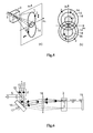
- Fig. 6 shows the proposed device for multiplexing in time of light pulses generated by separate laser sources, which scans the propagating light pulses trajectories in the second-order nonlinear medium in order to avoid its optical damage and the phase-matching condition mismatch because of heating generated by absorbed radiation in the second-order nonlinear medium.
- Device is for generation of the light- pulse sequences with the summed optical frequency and high energy and high average power.
- Device is composed from separate laser sources (1 1 -1 n ) that generates light pulses 2, dichroic mirror 15, which is transparent for the light beams 2 generated by the separate laser sources (1 1 -1 n ), the wedge mirror 16, rotating around its axis 17 for changing-scanning of the propagation direction of the light beams 2, the lens 18 placed in at its focal length from rotating mirror for summation of the light pulses 2 to the sequences 5 of the light pulses of the summed optical frequency 4, the mirror 19 to reflect back the sequences 5 of the light pulses of the summed optical frequency 4.
- the sequences 5 of the summed optical frequency pulses 4 pass through the second-order nonlinear medium 3, the lens 18, are reflected from rotating mirror 16 and are reflected out by the dichroic mirror 15.
- the sequences 5 of the light pulses of the summed optical frequency 4 propagate in one steady trajectory.
- Fig. 7 shows the proposed device for multiplexing in time the light pulses 2 generated by separate laser sources, which scans the propagating trajectories of light pulses in the second-order nonlinear medium, to avoid its optical damage and the phase-matching condition mismatch because of heat generated by absorbed radiation in the second- order nonlinear medium.
- the device is for generation of the light pulse sequences with the summed optical frequency and high energy and high average power.
- the device is composed from the second-order nonlinear media 3 that are attached to the rotating cylinder 20.
- the rotating cylinder 20 is made of material with a high thermal conductivity and has good thermal contact with the second-order nonlinear media 3.
- the light pulses 2 generated by separate laser sources are directed to the second-order nonlinear media 3, attached to the rotating cylinder 20, where the pulses 2 are transformed to sequences of the light pulses of the summed optical frequency.
- the initial light pulses 2 and generated sequences 5 of the summed optical frequency pulses 4 propagate through different places in the second-order nonlinear media 3, and heat generated due to optical absorption in the second-order nonlinear medium 3 is dissipated.
Landscapes
- Physics & Mathematics (AREA)
- Electromagnetism (AREA)
- Optics & Photonics (AREA)
- Engineering & Computer Science (AREA)
- Plasma & Fusion (AREA)
- Nonlinear Science (AREA)
- General Physics & Mathematics (AREA)
- Lasers (AREA)
- Optical Modulation, Optical Deflection, Nonlinear Optics, Optical Demodulation, Optical Logic Elements (AREA)
Applications Claiming Priority (1)
| Application Number | Priority Date | Filing Date | Title |
|---|---|---|---|
| LT2013501A LT6140B (lt) | 2013-07-22 | 2013-07-22 | Šviesos impulsų sutankinimo laike būdas ir įrenginys |
Publications (2)
| Publication Number | Publication Date |
|---|---|
| EP2830169A2 true EP2830169A2 (de) | 2015-01-28 |
| EP2830169A3 EP2830169A3 (de) | 2015-04-01 |
Family
ID=50732756
Family Applications (1)
| Application Number | Title | Priority Date | Filing Date |
|---|---|---|---|
| EP14160263.1A Withdrawn EP2830169A3 (de) | 2013-07-22 | 2014-03-17 | Verfahren und Einrichtung zum Multiplexen von Lichtimpulsen in der Zeit |
Country Status (2)
| Country | Link |
|---|---|
| EP (1) | EP2830169A3 (de) |
| LT (1) | LT6140B (de) |
Cited By (2)
| Publication number | Priority date | Publication date | Assignee | Title |
|---|---|---|---|---|
| WO2022108824A1 (en) * | 2020-11-19 | 2022-05-27 | C.R. Bard, Inc. | Laser module and methods thereof |
| US11486818B2 (en) * | 2020-05-26 | 2022-11-01 | Wisconsin Alumni Research Foundation | Methods and systems for coherent multidimensional spectroscopy |
Citations (2)
| Publication number | Priority date | Publication date | Assignee | Title |
|---|---|---|---|---|
| DE102007002472A1 (de) | 2007-01-11 | 2008-07-17 | Lpkf Laser & Electronics Ag | Mehrkanaliger Laser |
| EP2194426A1 (de) | 2008-11-13 | 2010-06-09 | UAB "Ekspla" | Verfahren und Vorrichtung zur Bündelung von Laserstrahlen |
Family Cites Families (6)
| Publication number | Priority date | Publication date | Assignee | Title |
|---|---|---|---|---|
| AU6875000A (en) * | 1999-09-10 | 2001-04-17 | Nikon Corporation | Exposure device with laser device |
| US9008132B2 (en) * | 2010-04-21 | 2015-04-14 | Ipg Photonics Corporation | Multiple wavelength raman laser |
| TWI414751B (zh) * | 2010-05-25 | 2013-11-11 | Univ Nat Yunlin Sci & Tech | 旋轉角度量測系統 |
| EP2751616A4 (de) * | 2011-08-29 | 2015-12-02 | Genia Photonics Inc | System und verfahren zur synchronisierung von lichtpulsen an einem ausgewählten standort |
| KR101931967B1 (ko) * | 2011-09-19 | 2018-12-27 | 삼성전자 주식회사 | 광학 현미경의 자동 초점 조절 장치 |
| KR101337529B1 (ko) * | 2012-01-12 | 2013-12-06 | 인하대학교 산학협력단 | 이중위상반전과 원자결맞음 위상조절에 기초한 양자메모리 및 이의 이중위상반전된 포톤에코 방법 |
-
2013
- 2013-07-22 LT LT2013501A patent/LT6140B/lt not_active IP Right Cessation
-
2014
- 2014-03-17 EP EP14160263.1A patent/EP2830169A3/de not_active Withdrawn
Patent Citations (2)
| Publication number | Priority date | Publication date | Assignee | Title |
|---|---|---|---|---|
| DE102007002472A1 (de) | 2007-01-11 | 2008-07-17 | Lpkf Laser & Electronics Ag | Mehrkanaliger Laser |
| EP2194426A1 (de) | 2008-11-13 | 2010-06-09 | UAB "Ekspla" | Verfahren und Vorrichtung zur Bündelung von Laserstrahlen |
Cited By (3)
| Publication number | Priority date | Publication date | Assignee | Title |
|---|---|---|---|---|
| US11486818B2 (en) * | 2020-05-26 | 2022-11-01 | Wisconsin Alumni Research Foundation | Methods and systems for coherent multidimensional spectroscopy |
| WO2022108824A1 (en) * | 2020-11-19 | 2022-05-27 | C.R. Bard, Inc. | Laser module and methods thereof |
| JP2023551170A (ja) * | 2020-11-19 | 2023-12-07 | シー・アール・バード・インコーポレーテッド | レーザモジュールおよびその方法 |
Also Published As
| Publication number | Publication date |
|---|---|
| EP2830169A3 (de) | 2015-04-01 |
| LT6140B (lt) | 2015-04-27 |
| LT2013501A (lt) | 2015-01-26 |
Similar Documents
| Publication | Publication Date | Title |
|---|---|---|
| JP7745668B2 (ja) | レーザビームの方法及びシステム | |
| Baltuška et al. | Controlling the carrier-envelope phase of ultrashort light pulses with optical parametric amplifiers | |
| US10020632B2 (en) | UV-visible laser system having ultrashort highpower and/or high-energy pulses | |
| US7630418B2 (en) | Laser system for generation of high-power sub-nanosecond pulses with controllable wavelength in 2-15 μm region | |
| US6047011A (en) | Optical harmonic generator | |
| JP6478804B2 (ja) | カスケード光高調波発生 | |
| US10042232B2 (en) | Optical amplifier arrangement, laser amplifier system and process | |
| JP5388166B2 (ja) | テラヘルツ波の発生装置及び発生方法 | |
| CN105186273B (zh) | 一种双端面泵浦光参量振荡器 | |
| Kwon et al. | Experimental demonstration of spatial-mode-selective frequency up-conversion in a multimode χ (2) waveguide | |
| CN108292073B (zh) | 通过n-波混合来产生或放大光脉冲的包括快速调制装置的非线性光学系统 | |
| US5136599A (en) | Apparatus and method for increasing the bandwidth of a laser beam | |
| EP1724634A1 (de) | Verfahren und Vorrichtung für parametrische Verstärkung von ultrakurzen Lichtimpulsen | |
| Pennington et al. | Effect of bandwidth on beam smoothing and frequency conversion at the third harmonic of the Nova laser | |
| JP3573334B2 (ja) | 光発生方法及び光源 | |
| LT6140B (lt) | Šviesos impulsų sutankinimo laike būdas ir įrenginys | |
| Riesbeck et al. | A high power laser system at 540 nm with beam coupling by second harmonic generation | |
| CN105305214A (zh) | 一种获得高重频、大能量紫外可调谐激光脉冲的方法 | |
| EP2621032A2 (de) | Verfahren und Vorrichtung zur Summenfrequenzerzeugung von Lichtimpulsen | |
| CN102664344A (zh) | 一种高能量激光倍频调q装置 | |
| Miyanaga et al. | The GEKKO XII-HIPER (high intensity plasma experimental research) system relevant to ignition targets | |
| Jahanzeb et al. | A Dual-Sideband Attosecond Interferometry Setup | |
| Miyanaga et al. | Smoothing of focused-beam pattern using two-dimensional spectral dispersion performed at GEKKO XII | |
| HK40084594A (en) | Laser beams methods and systems | |
| CN113131312A (zh) | 一种深紫外激光器的和频发生器 |
Legal Events
| Date | Code | Title | Description |
|---|---|---|---|
| 17P | Request for examination filed |
Effective date: 20140613 |
|
| AK | Designated contracting states |
Kind code of ref document: A2 Designated state(s): AL AT BE BG CH CY CZ DE DK EE ES FI FR GB GR HR HU IE IS IT LI LT LU LV MC MK MT NL NO PL PT RO RS SE SI SK SM TR |
|
| AX | Request for extension of the european patent |
Extension state: BA ME |
|
| PUAI | Public reference made under article 153(3) epc to a published international application that has entered the european phase |
Free format text: ORIGINAL CODE: 0009012 |
|
| PUAL | Search report despatched |
Free format text: ORIGINAL CODE: 0009013 |
|
| AK | Designated contracting states |
Kind code of ref document: A3 Designated state(s): AL AT BE BG CH CY CZ DE DK EE ES FI FR GB GR HR HU IE IS IT LI LT LU LV MC MK MT NL NO PL PT RO RS SE SI SK SM TR |
|
| AX | Request for extension of the european patent |
Extension state: BA ME |
|
| RIC1 | Information provided on ipc code assigned before grant |
Ipc: H04J 14/08 20060101ALN20150226BHEP Ipc: G02F 1/35 20060101ALI20150226BHEP Ipc: H01S 3/10 20060101ALN20150226BHEP Ipc: H01S 3/23 20060101AFI20150226BHEP Ipc: H01S 3/00 20060101ALI20150226BHEP |
|
| 17Q | First examination report despatched |
Effective date: 20151117 |
|
| RIC1 | Information provided on ipc code assigned before grant |
Ipc: G02F 1/35 20060101ALI20190131BHEP Ipc: H01S 3/00 20060101ALI20190131BHEP Ipc: H01S 3/10 20060101ALN20190131BHEP Ipc: H04J 14/08 20060101ALN20190131BHEP Ipc: H01S 3/23 20060101AFI20190131BHEP |
|
| RIC1 | Information provided on ipc code assigned before grant |
Ipc: G02F 1/35 20060101ALI20190205BHEP Ipc: H04J 14/08 20060101ALN20190205BHEP Ipc: H01S 3/10 20060101ALN20190205BHEP Ipc: H01S 3/00 20060101ALI20190205BHEP Ipc: H01S 3/23 20060101AFI20190205BHEP |
|
| RIC1 | Information provided on ipc code assigned before grant |
Ipc: H01S 3/10 20060101ALN20190212BHEP Ipc: H04J 14/08 20060101ALN20190212BHEP Ipc: H01S 3/00 20060101ALI20190212BHEP Ipc: G02F 1/35 20060101ALI20190212BHEP Ipc: H01S 3/23 20060101AFI20190212BHEP |
|
| RIC1 | Information provided on ipc code assigned before grant |
Ipc: H01S 3/00 20060101ALI20190321BHEP Ipc: H01S 3/10 20060101ALN20190321BHEP Ipc: H01S 3/23 20060101AFI20190321BHEP Ipc: G02F 1/35 20060101ALI20190321BHEP Ipc: H04J 14/08 20060101ALN20190321BHEP |
|
| RIC1 | Information provided on ipc code assigned before grant |
Ipc: H04J 14/08 20060101ALN20190322BHEP Ipc: H01S 3/00 20060101ALI20190322BHEP Ipc: H01S 3/23 20060101AFI20190322BHEP Ipc: G02F 1/35 20060101ALI20190322BHEP Ipc: H01S 3/10 20060101ALN20190322BHEP |
|
| RIC1 | Information provided on ipc code assigned before grant |
Ipc: H04J 14/08 20060101ALN20190403BHEP Ipc: H01S 3/00 20060101ALI20190403BHEP Ipc: G02F 1/35 20060101ALI20190403BHEP Ipc: H01S 3/23 20060101AFI20190403BHEP Ipc: H01S 3/10 20060101ALN20190403BHEP |
|
| RIC1 | Information provided on ipc code assigned before grant |
Ipc: H04J 14/08 20060101ALN20190405BHEP Ipc: G02F 1/35 20060101ALI20190405BHEP Ipc: H01S 3/10 20060101ALN20190405BHEP Ipc: H01S 3/23 20060101AFI20190405BHEP Ipc: H01S 3/00 20060101ALI20190405BHEP |
|
| RIC1 | Information provided on ipc code assigned before grant |
Ipc: G02F 1/35 20060101ALI20190415BHEP Ipc: H01S 3/23 20060101AFI20190415BHEP Ipc: H01S 3/10 20060101ALN20190415BHEP Ipc: H01S 3/00 20060101ALI20190415BHEP Ipc: H04J 14/08 20060101ALN20190415BHEP |
|
| RIC1 | Information provided on ipc code assigned before grant |
Ipc: H01S 3/23 20060101AFI20190508BHEP Ipc: H01S 3/10 20060101ALN20190508BHEP Ipc: H01S 3/00 20060101ALI20190508BHEP Ipc: H04J 14/08 20060101ALN20190508BHEP Ipc: G02F 1/35 20060101ALI20190508BHEP |
|
| STAA | Information on the status of an ep patent application or granted ep patent |
Free format text: STATUS: THE APPLICATION IS DEEMED TO BE WITHDRAWN |
|
| 18D | Application deemed to be withdrawn |
Effective date: 20201001 |