EP2829722A1 - Ignition timing control device of internal combustion engine - Google Patents
Ignition timing control device of internal combustion engine Download PDFInfo
- Publication number
- EP2829722A1 EP2829722A1 EP13763795.5A EP13763795A EP2829722A1 EP 2829722 A1 EP2829722 A1 EP 2829722A1 EP 13763795 A EP13763795 A EP 13763795A EP 2829722 A1 EP2829722 A1 EP 2829722A1
- Authority
- EP
- European Patent Office
- Prior art keywords
- timing
- retard
- water temperature
- startup
- temperature
- Prior art date
- Legal status (The legal status is an assumption and is not a legal conclusion. Google has not performed a legal analysis and makes no representation as to the accuracy of the status listed.)
- Granted
Links
Images


Classifications
-
- F—MECHANICAL ENGINEERING; LIGHTING; HEATING; WEAPONS; BLASTING
- F02—COMBUSTION ENGINES; HOT-GAS OR COMBUSTION-PRODUCT ENGINE PLANTS
- F02P—IGNITION, OTHER THAN COMPRESSION IGNITION, FOR INTERNAL-COMBUSTION ENGINES; TESTING OF IGNITION TIMING IN COMPRESSION-IGNITION ENGINES
- F02P5/00—Advancing or retarding ignition; Control therefor
- F02P5/04—Advancing or retarding ignition; Control therefor automatically, as a function of the working conditions of the engine or vehicle or of the atmospheric conditions
- F02P5/05—Advancing or retarding ignition; Control therefor automatically, as a function of the working conditions of the engine or vehicle or of the atmospheric conditions using mechanical means
- F02P5/14—Advancing or retarding ignition; Control therefor automatically, as a function of the working conditions of the engine or vehicle or of the atmospheric conditions using mechanical means dependent on specific conditions other than engine speed or engine fluid pressure, e.g. temperature
-
- F—MECHANICAL ENGINEERING; LIGHTING; HEATING; WEAPONS; BLASTING
- F01—MACHINES OR ENGINES IN GENERAL; ENGINE PLANTS IN GENERAL; STEAM ENGINES
- F01N—GAS-FLOW SILENCERS OR EXHAUST APPARATUS FOR MACHINES OR ENGINES IN GENERAL; GAS-FLOW SILENCERS OR EXHAUST APPARATUS FOR INTERNAL-COMBUSTION ENGINES
- F01N3/00—Exhaust or silencing apparatus having means for purifying, rendering innocuous, or otherwise treating exhaust
- F01N3/08—Exhaust or silencing apparatus having means for purifying, rendering innocuous, or otherwise treating exhaust for rendering innocuous
- F01N3/10—Exhaust or silencing apparatus having means for purifying, rendering innocuous, or otherwise treating exhaust for rendering innocuous by thermal or catalytic conversion of noxious components of exhaust
- F01N3/18—Exhaust or silencing apparatus having means for purifying, rendering innocuous, or otherwise treating exhaust for rendering innocuous by thermal or catalytic conversion of noxious components of exhaust characterised by methods of operation; Control
- F01N3/20—Exhaust or silencing apparatus having means for purifying, rendering innocuous, or otherwise treating exhaust for rendering innocuous by thermal or catalytic conversion of noxious components of exhaust characterised by methods of operation; Control specially adapted for catalytic conversion
- F01N3/2006—Periodically heating or cooling catalytic reactors, e.g. at cold starting or overheating
-
- F—MECHANICAL ENGINEERING; LIGHTING; HEATING; WEAPONS; BLASTING
- F02—COMBUSTION ENGINES; HOT-GAS OR COMBUSTION-PRODUCT ENGINE PLANTS
- F02D—CONTROLLING COMBUSTION ENGINES
- F02D41/00—Electrical control of supply of combustible mixture or its constituents
- F02D41/02—Circuit arrangements for generating control signals
- F02D41/021—Introducing corrections for particular conditions exterior to the engine
- F02D41/0235—Introducing corrections for particular conditions exterior to the engine in relation with the state of the exhaust gas treating apparatus
- F02D41/024—Introducing corrections for particular conditions exterior to the engine in relation with the state of the exhaust gas treating apparatus to increase temperature of the exhaust gas treating apparatus
-
- F—MECHANICAL ENGINEERING; LIGHTING; HEATING; WEAPONS; BLASTING
- F02—COMBUSTION ENGINES; HOT-GAS OR COMBUSTION-PRODUCT ENGINE PLANTS
- F02P—IGNITION, OTHER THAN COMPRESSION IGNITION, FOR INTERNAL-COMBUSTION ENGINES; TESTING OF IGNITION TIMING IN COMPRESSION-IGNITION ENGINES
- F02P5/00—Advancing or retarding ignition; Control therefor
- F02P5/04—Advancing or retarding ignition; Control therefor automatically, as a function of the working conditions of the engine or vehicle or of the atmospheric conditions
- F02P5/145—Advancing or retarding ignition; Control therefor automatically, as a function of the working conditions of the engine or vehicle or of the atmospheric conditions using electrical means
- F02P5/15—Digital data processing
- F02P5/1502—Digital data processing using one central computing unit
- F02P5/1506—Digital data processing using one central computing unit with particular means during starting
-
- F—MECHANICAL ENGINEERING; LIGHTING; HEATING; WEAPONS; BLASTING
- F02—COMBUSTION ENGINES; HOT-GAS OR COMBUSTION-PRODUCT ENGINE PLANTS
- F02P—IGNITION, OTHER THAN COMPRESSION IGNITION, FOR INTERNAL-COMBUSTION ENGINES; TESTING OF IGNITION TIMING IN COMPRESSION-IGNITION ENGINES
- F02P5/00—Advancing or retarding ignition; Control therefor
- F02P5/04—Advancing or retarding ignition; Control therefor automatically, as a function of the working conditions of the engine or vehicle or of the atmospheric conditions
- F02P5/145—Advancing or retarding ignition; Control therefor automatically, as a function of the working conditions of the engine or vehicle or of the atmospheric conditions using electrical means
- F02P5/15—Digital data processing
- F02P5/1502—Digital data processing using one central computing unit
- F02P5/1508—Digital data processing using one central computing unit with particular means during idling
-
- F—MECHANICAL ENGINEERING; LIGHTING; HEATING; WEAPONS; BLASTING
- F01—MACHINES OR ENGINES IN GENERAL; ENGINE PLANTS IN GENERAL; STEAM ENGINES
- F01N—GAS-FLOW SILENCERS OR EXHAUST APPARATUS FOR MACHINES OR ENGINES IN GENERAL; GAS-FLOW SILENCERS OR EXHAUST APPARATUS FOR INTERNAL-COMBUSTION ENGINES
- F01N2410/00—By-passing, at least partially, exhaust from inlet to outlet of apparatus, to atmosphere or to other device
- F01N2410/06—By-passing, at least partially, exhaust from inlet to outlet of apparatus, to atmosphere or to other device at cold starting
-
- F—MECHANICAL ENGINEERING; LIGHTING; HEATING; WEAPONS; BLASTING
- F02—COMBUSTION ENGINES; HOT-GAS OR COMBUSTION-PRODUCT ENGINE PLANTS
- F02D—CONTROLLING COMBUSTION ENGINES
- F02D2200/00—Input parameters for engine control
- F02D2200/02—Input parameters for engine control the parameters being related to the engine
- F02D2200/021—Engine temperature
-
- Y—GENERAL TAGGING OF NEW TECHNOLOGICAL DEVELOPMENTS; GENERAL TAGGING OF CROSS-SECTIONAL TECHNOLOGIES SPANNING OVER SEVERAL SECTIONS OF THE IPC; TECHNICAL SUBJECTS COVERED BY FORMER USPC CROSS-REFERENCE ART COLLECTIONS [XRACs] AND DIGESTS
- Y02—TECHNOLOGIES OR APPLICATIONS FOR MITIGATION OR ADAPTATION AGAINST CLIMATE CHANGE
- Y02T—CLIMATE CHANGE MITIGATION TECHNOLOGIES RELATED TO TRANSPORTATION
- Y02T10/00—Road transport of goods or passengers
- Y02T10/10—Internal combustion engine [ICE] based vehicles
- Y02T10/12—Improving ICE efficiencies
-
- Y—GENERAL TAGGING OF NEW TECHNOLOGICAL DEVELOPMENTS; GENERAL TAGGING OF CROSS-SECTIONAL TECHNOLOGIES SPANNING OVER SEVERAL SECTIONS OF THE IPC; TECHNICAL SUBJECTS COVERED BY FORMER USPC CROSS-REFERENCE ART COLLECTIONS [XRACs] AND DIGESTS
- Y02—TECHNOLOGIES OR APPLICATIONS FOR MITIGATION OR ADAPTATION AGAINST CLIMATE CHANGE
- Y02T—CLIMATE CHANGE MITIGATION TECHNOLOGIES RELATED TO TRANSPORTATION
- Y02T10/00—Road transport of goods or passengers
- Y02T10/10—Internal combustion engine [ICE] based vehicles
- Y02T10/40—Engine management systems
Definitions
- the present invention relates to an ignition timing control device of an internal combustion engine, and more particularly to a technique of correcting an ignition timing to retard side (retard-angle side) in order to attain a quick activation of catalyst during an idling generated after a cold start of the internal combustion engine.
- the ignition timing is corrected toward the retard side so as to increase an exhaust gas temperature and thereby promote an activation of catalyst during an idling operation after a cold start of an internal combustion engine.
- retard amount and retard-correcting period for the ignition timing are set based on a temperature of cooling water during the idling operation generated after the cold start. Specifically, in order to promote temperature rise of the exhaust gas, the retard amount is set at a larger value as an engine-start-time temperature of the cooling water becomes lower. Moreover, the retard-correcting period is set at a larger value as the engine-start-time temperature of the cooling water becomes lower.
- Patent Literature 1 Japanese Patent Application Publication No. 2004-116372 , FIGS. 3-7 , paragraphs [0039]-[0045] etc.
- the retard amount and the retard-correcting period can be set at large values because the combustion is relatively stable. However, in this situation, there is a possibility that the retard amount and the retard-correcting period are set at small values so that a sufficient effect of temperature rise of exhaust gas is not obtained.
- an ignition timing control device of an internal combustion engine comprising: an ignition device configured to ignite air-fuel mixture of a combustion chamber of the internal combustion engine; a catalyst interposed in an exhaust passage of the internal combustion engine and configured to purify an exhaust gas flowing in the exhaust passage; a water temperature detecting means configured to detect a water temperature of a cooling water of the internal combustion engine; an ignition-timing retarding means configured to correct an ignition timing of the ignition device to a retard side such that an activation of the catalyst is promoted, during an idling operation generated after a cold start of the internal combustion engine; and a startup-timing-water-temperature retard-amount calculating means configured to calculate a retard amount by which the ignition-timing retarding means retards the ignition timing, based on a startup-timing water temperature which is the water temperature indicated at a startup timing of the internal combustion engine, wherein the startup-timing-water-temperature retard-amount calculating means is configured to set the retard amount at a larger level as the startup-
- the retard amount is set at a larger level as the startup-timing water temperature becomes higher, i.e. the retard amount is set at a smaller level as the startup-timing water temperature becomes lower. Accordingly, if the startup-timing water temperature is very low, for example, at the time of very-low-temperature startup of the engine, the retard amount is set at a small value. Hence, the worsening of combustion stability is suppressed to ensure initial drivability, so that the idle roughness can be inhibited from occurring.
- the retard amount is set at a smaller level as the startup-timing water temperature becomes higher i.e. comes closer to the activating temperature of the catalyst. Hence, the retard amount is inhibited from being excessively large so that the worsening of drivability and the worsening of fuel economy can be suppressed.
- the temperature rise of exhaust gas is promoted to improve the exhaust emission performance by virtue of the quick activation of catalyst while ensuring the combustion stability and favorable drivability.
- FIG. 1 is an explanatory view showing a system configuration of an in-cylinder-direct-injection-type spark-ignition internal combustion engine to which one embodiment of the present invention is applied.
- a piston 2 is disposed in a cylinder 1A of the internal combustion engine 1 such that the piston 2 is able to reciprocate inside the cylinder.
- a combustion chamber 3 formed above the piston 2 communicates (is connected) through an intake valve (not shown) with an intake passage 4.
- the combustion chamber 3 communicates (is connected) through an exhaust valve (not shown) with an exhaust passage 5.
- An air flow meter 6 for detecting an intake air flow volume (intake-air amount) is provided in the intake passage 4.
- an electronically-controlled throttle valve 7 is provided in the intake passage 4.
- An opening degree of the electronically-controlled throttle valve 7 is controlled through an actuator 8 by control signals.
- a catalytic converter 10 for purifying exhaust emission is provided in the exhaust passage 5.
- two air-fuel ratio sensors 11 and 12 are provided respectively upstream and downstream of the catalytic converter 10.
- a spark plug 14 which functions as an ignition device is provided at a top center portion of the combustion chamber 3. Moreover, a fuel injection valve 15 which injects fuel directly into the combustion chamber 3 is disposed at a lateral portion of the combustion chamber 3 on the side of the intake passage 4. Fuel whose pressure is adjusted to a given pressure by a high-pressure fuel pump 16 and a pressure regulator 17 is supplied through a high-pressure fuel passage 18 to the fuel injection valve 15. Accordingly, when the fuel injection valve 15 of each cylinder opens by a control pulse, fuel whose amount is according to an open period of the fuel injection valve 15 is injected.
- a reference sign 19 denotes a fuel pressure sensor for detecting fuel pressure
- a reference sign 20 denotes a low-pressure fuel pump for feeding fuel to the high-pressure fuel pump 16.
- the structure according to the present invention is not limited to the in-cylinder-direct-injection type, and may instead have a port-injection type in which fuel is injected into an intake port.
- the internal combustion engine 1 includes a water temperature sensor 21, an oil temperature sensor 24 and a crank angle sensor 22.
- the water temperature sensor 21 detects a temperature of engine cooling water, as a water temperature detecting means (or section).
- the oil temperature sensor 24 detects a temperature of engine hydraulic oil.
- the crank angle sensor 22 detects a crank angle.
- an accelerator opening-angle sensor 23 is provided which detects a depressed amount (i.e. position) of an accelerator pedal by a driver.
- Fuel injection quantity, fuel injection timing, ignition timing and the like of the internal combustion engine 1 are controlled by a control unit 25.
- the control unit 25 receives detection signals (input signals) of the above-mentioned various sensors. According to an engine operating condition given by these input signals, the control unit 25 determines whether a combustion mode should be a homogeneous combustion or a stratified-charge combustion, i.e., selects one from the homogeneous combustion and the stratified-charge combustion as the combustion mode. In conformity with the selected combustion mode, the control unit 25 controls the opening angle of the electronically-controlled throttle valve 7, the fuel injection timing and fuel injection quantity of the fuel injection valve 15, the ignition timing of the spark plug 14, and the like.
- FIG. 2 is a flowchart showing a control flow of the retard correction for the ignition timing under an idling state which occurs immediately after the cold start.
- the control unit 25 has already stored the routine of this control flow. This routine is repeatedly executed at predetermined intervals (for example, every 10 milliseconds).
- step S11 it is judged whether or not a current engine state is the idling state generated (immediately) after the cold start of the internal combustion engine, on the basis of the detection signal of the water temperature sensor 21 and the like. If the current engine state is not the idling state generated after the cold start, the program proceeds to step S16.
- a retard amount (lag amount) of the ignition timing is set at zero. More specifically, a retard amount which is used in the retard correction for the ignition timing at the time of the idling state generated immediately after the cold start is set at zero. Then, the program proceeds to an after-mentioned step S17.
- step S12 it is judged whether or not a current moment is a startup timing (i.e., a first-time routine immediately after the cold start) of the engine, for example by using a start-up flag F which is set at zero at the time of deactivation (stop) of the engine. If the start-up flag F takes "0" at step S12, it is determined that the current moment is the startup timing of the engine. Then, the start-up flag F is set at "1", and the program proceeds to step S13.
- a startup timing i.e., a first-time routine immediately after the cold start
- start-up flag F which is set at zero at the time of deactivation (stop) of the engine. If the start-up flag F takes "0" at step S12, it is determined that the current moment is the startup timing of the engine. Then, the start-up flag F is set at "1", and the program proceeds to step S13.
- a retard amount S of the ignition timing is calculated based on a water temperature value sensed by the water temperature sensor 21, i.e., based on a water temperature value indicated at the startup timing of the engine (hereinafter called "startup-timing water temperature"). Then, the calculated retard amount S is memorized and stored in a storage device such as a RAM included in the control unit 25. That is, the program proceeds from step S12 to step S13 only once at the startup timing of the engine, in order to calculate and store the retard amount S based on the startup-timing water temperature.
- step S14 a retard amount R of the ignition timing is calculated based on a current water temperature value (hereinafter called "current water temperature”) sensed by the water temperature sensor 21.
- current water temperature a current water temperature value
- a smaller one of the retard amount S calculated based on the startup-timing water temperature and the retard amount R calculated based on the current water temperature is selected as a basic retard amount.
- the ignition timing is corrected toward a retard side at the time of the idling state generated after the cold start.
- step S17 it is judged whether or not an integration value of a catalyst-supplied heat quantity (i.e. a heat quantity supplied to the catalyst) is smaller than or equal to a predetermined threshold value * (see FIG. 4 ).
- the integration value of the catalyst-supplied heat quantity is calculated in view of the intake-air amount detected by the air flow meter 6, an engine load, a driving condition and the like.
- step S18 the retard correction of the ignition timing is carried out by using the basic retard amount calculated at step S15 as the (actual) retard amount.
- the retard correction is not carried out because the retard amount has been set at zero at step S16.
- the program proceeds to steps S19 and S20 so that the retard correction is terminated.
- the (actual) retard amount is gradually reduced at a certain rate when terminating the retard correction. Specifically, the retard amount is repeatedly reduced by a predetermined amount @ at step S20 until the judgment process of step S19 determines that the retard amount is equal to zero.
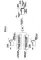
- FIG. 3 is a functional block diagram showing control contents of steps S13 to S15.
- the retard amount S is set at a larger value as the startup-timing water temperature becomes higher in the case that the startup-timing water temperature is lower than or equal to a predetermined temperature ⁇ . That is, in this case, the retard amount S is calculated as a value enlarged with the enlargement of the startup-timing water temperature.
- the retard amount S is set at a smaller value as the startup-timing water temperature becomes higher. That is, in this case, the retard amount S is calculated as a value lowered with the enlargement of the startup-timing water temperature. Accordingly, the retard amount S takes its maximum value when the startup-timing water temperature is near the predetermined temperature ⁇ , and the retard amount S becomes smaller as the startup-timing water temperature is farther from the predetermined temperature ⁇ .
- a relation profile between the retard amount R and the current water temperature which is used when calculating the retard amount R by use of the current water temperature is the same as a relation profile between the retard amount S and the startup-timing water temperature which is used when calculating the retard amount S by use of the startup-timing water temperature. That is, as shown in FIGS. 3(A) and 3(B) , the retard amount S and the retard amount R are respectively obtained by using an identical control map (or control table). Hence, in the same manner as the retard amount S, the retard amount R is set at a larger value as the current water temperature becomes higher in the case that the current water temperature is lower than or equal to the predetermined temperature ⁇ .
- the retard amount R is calculated as a value enlarged with the enlargement of the current water temperature.
- the retard amount R is set at a smaller value as the current water temperature becomes higher. That is, in this case, the retard amount R is calculated as a value lowered with the enlargement of the current water temperature. Accordingly, the retard amount R takes its maximum value when the current water temperature is near the predetermined temperature ⁇ , and the retard amount R becomes smaller as the current water temperature is farther from the predetermined temperature ⁇ .
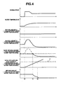
- FIG. 4 is a timing chart showing a driving situation of transfer from the cold start to the idling state, in a case that such a control of the embodiment is applied.
- the retard correction is carried out by using the retard amount S as the basic retard amount because the retard amount S obtained from the startup-timing water temperature is lower than the retard amount R obtained from the current water temperature.
- the retard amount R obtained from the current water temperature is lower than the retard amount S obtained from the startup-timing water temperature.
- the retard correction is carried out by using the retard amount R as the basic retard amount.
- the (actual) retard amount is gradually reduced in an interval between the timing t1 and a timing t2.
- the integration value of the catalyst-supplied heat quantity reaches the predetermined threshold value * at the timing t2 (see FIG. 4 ). From the timing t2, the above-mentioned terminating process of the retard correction of steps S19 and S20 is carried out so that the (actual) retard amount is gradually reduced toward zero at the certain rate (by the predetermined amount @).
- the (actual) retard amount may be calculated by using only the retard amount S obtained from the startup-timing water temperature, without using the retard amount R obtained from the current water temperature. That is, the retard amount may be calculated by omitting the process of steps S14 and S15 in FIG. 2 .
Landscapes
- Engineering & Computer Science (AREA)
- Chemical & Material Sciences (AREA)
- General Engineering & Computer Science (AREA)
- Combustion & Propulsion (AREA)
- Mechanical Engineering (AREA)
- Chemical Kinetics & Catalysis (AREA)
- Signal Processing (AREA)
- Theoretical Computer Science (AREA)
- Health & Medical Sciences (AREA)
- Toxicology (AREA)
- Electrical Control Of Ignition Timing (AREA)
- Exhaust Gas After Treatment (AREA)
- Combined Controls Of Internal Combustion Engines (AREA)
Abstract
Description
- The present invention relates to an ignition timing control device of an internal combustion engine, and more particularly to a technique of correcting an ignition timing to retard side (retard-angle side) in order to attain a quick activation of catalyst during an idling generated after a cold start of the internal combustion engine.
- Some technology is known in which the ignition timing is corrected toward the retard side so as to increase an exhaust gas temperature and thereby promote an activation of catalyst during an idling operation after a cold start of an internal combustion engine. For example, in
Patent Literature 1, retard amount and retard-correcting period for the ignition timing are set based on a temperature of cooling water during the idling operation generated after the cold start. Specifically, in order to promote temperature rise of the exhaust gas, the retard amount is set at a larger value as an engine-start-time temperature of the cooling water becomes lower. Moreover, the retard-correcting period is set at a larger value as the engine-start-time temperature of the cooling water becomes lower. - Patent Literature 1 : Japanese Patent Application Publication No.
2004-116372 FIGS. 3-7 , paragraphs [0039]-[0045] etc. - However, in the case that the retard amount and the retard-correcting period are more enlarged as the engine-start-time temperature of the cooling water becomes lower as mentioned above, a combustion stability is worsened if the engine-start-time temperature of the cooling water is very low, for example, at the time of very-low-temperature startup of the engine. This is because the retard amount and the retard-correcting period are set at large values although the combustion is not yet stable. As a result, there is a risk that a drivability is worsened due to a generation of idle roughness. On the other hand, if the engine-start-time temperature of the cooling water is relatively high, i.e. if the engine-start-time temperature of the cooling water is near an activating temperature of the catalyst, the retard amount and the retard-correcting period can be set at large values because the combustion is relatively stable. However, in this situation, there is a possibility that the retard amount and the retard-correcting period are set at small values so that a sufficient effect of temperature rise of exhaust gas is not obtained.
- It is therefore an object of the present invention to provide an ignition timing control device of an internal combustion engine, devised to promote a temperature rise of exhaust gas by a retard correction of the ignition timing and to improve an exhaust performance by virtue of quick activation of the catalyst while securing combustion stability and favorable drivability.
- According to the present invention, there is provided an ignition timing control device of an internal combustion engine, comprising: an ignition device configured to ignite air-fuel mixture of a combustion chamber of the internal combustion engine; a catalyst interposed in an exhaust passage of the internal combustion engine and configured to purify an exhaust gas flowing in the exhaust passage; a water temperature detecting means configured to detect a water temperature of a cooling water of the internal combustion engine; an ignition-timing retarding means configured to correct an ignition timing of the ignition device to a retard side such that an activation of the catalyst is promoted, during an idling operation generated after a cold start of the internal combustion engine; and a startup-timing-water-temperature retard-amount calculating means configured to calculate a retard amount by which the ignition-timing retarding means retards the ignition timing, based on a startup-timing water temperature which is the water temperature indicated at a startup timing of the internal combustion engine, wherein the startup-timing-water-temperature retard-amount calculating means is configured to set the retard amount at a larger level as the startup-timing water temperature becomes higher, in a case that the startup-timing water temperature is lower than or equal to a predetermined temperature, and to set the retard amount at a smaller level as the startup-timing water temperature becomes higher, in a case that the startup-timing water temperature is higher than the predetermined temperature. That is, according to the present invention, the retard amount takes its maximum value when the startup-timing water temperature is equal to the predetermined temperature. The retard amount takes a smaller value as a difference between the startup-timing water temperature and the predetermined temperature becomes larger.
- As mentioned above, in the case that the startup-timing water temperature is lower than or equal to the predetermined temperature, the retard amount is set at a larger level as the startup-timing water temperature becomes higher, i.e. the retard amount is set at a smaller level as the startup-timing water temperature becomes lower. Accordingly, if the startup-timing water temperature is very low, for example, at the time of very-low-temperature startup of the engine, the retard amount is set at a small value. Hence, the worsening of combustion stability is suppressed to ensure initial drivability, so that the idle roughness can be inhibited from occurring.
- Moreover, because the combustion is stable in a situation that the startup-timing water temperature is around the predetermined temperature, a sufficiently large retard amount is set. Hence, the temperature rise of exhaust gas is promoted to early activate the catalyst, so that the exhaust performance can be enhanced.
- On the other hand, in a situation that the startup-timing water temperature is higher than the predetermined temperature, the retard amount is set at a smaller level as the startup-timing water temperature becomes higher i.e. comes closer to the activating temperature of the catalyst. Hence, the retard amount is inhibited from being excessively large so that the worsening of drivability and the worsening of fuel economy can be suppressed.
- According to the present invention, by properly adjusting the retard amount of the ignition timing in accordance with the startup-timing water temperature, the temperature rise of exhaust gas is promoted to improve the exhaust emission performance by virtue of the quick activation of catalyst while ensuring the combustion stability and favorable drivability.
-
- [
FIG. 1 ] A system configuration view of an internal combustion engine to which an ignition timing control device according to an embodiment of the present invention is applied. - [
FIG. 2 ] A flowchart illustrating a control flow of a retard correction for ignition timing. - [
FIG. 3 ] A functional block diagram illustrating a calculation process of a retard amount. - [
FIG. 4 ] A timing chart illustrating a driving situation of transfer from a cold start to an idling state in the case that the embodiment is applied to the internal combustion engine. - Hereinafter, the present invention will be explained based on embodiments referring to the drawings.
FIG. 1 is an explanatory view showing a system configuration of an in-cylinder-direct-injection-type spark-ignition internal combustion engine to which one embodiment of the present invention is applied. - A
piston 2 is disposed in acylinder 1A of theinternal combustion engine 1 such that thepiston 2 is able to reciprocate inside the cylinder. Acombustion chamber 3 formed above thepiston 2 communicates (is connected) through an intake valve (not shown) with an intake passage 4. Also, thecombustion chamber 3 communicates (is connected) through an exhaust valve (not shown) with anexhaust passage 5. Anair flow meter 6 for detecting an intake air flow volume (intake-air amount) is provided in the intake passage 4. Moreover, an electronically-controlled throttle valve 7 is provided in the intake passage 4. An opening degree of the electronically-controlled throttle valve 7 is controlled through anactuator 8 by control signals. Acatalytic converter 10 for purifying exhaust emission is provided in theexhaust passage 5. Moreover, two air-fuel ratio sensors catalytic converter 10. - A
spark plug 14 which functions as an ignition device is provided at a top center portion of thecombustion chamber 3. Moreover, afuel injection valve 15 which injects fuel directly into thecombustion chamber 3 is disposed at a lateral portion of thecombustion chamber 3 on the side of the intake passage 4. Fuel whose pressure is adjusted to a given pressure by a high-pressure fuel pump 16 and apressure regulator 17 is supplied through a high-pressure fuel passage 18 to thefuel injection valve 15. Accordingly, when thefuel injection valve 15 of each cylinder opens by a control pulse, fuel whose amount is according to an open period of thefuel injection valve 15 is injected. Areference sign 19 denotes a fuel pressure sensor for detecting fuel pressure, and areference sign 20 denotes a low-pressure fuel pump for feeding fuel to the high-pressure fuel pump 16. - It is noted that the structure according to the present invention is not limited to the in-cylinder-direct-injection type, and may instead have a port-injection type in which fuel is injected into an intake port.
- The
internal combustion engine 1 includes awater temperature sensor 21, anoil temperature sensor 24 and acrank angle sensor 22. Thewater temperature sensor 21 detects a temperature of engine cooling water, as a water temperature detecting means (or section). Theoil temperature sensor 24 detects a temperature of engine hydraulic oil. Thecrank angle sensor 22 detects a crank angle. Moreover, an accelerator opening-angle sensor 23 is provided which detects a depressed amount (i.e. position) of an accelerator pedal by a driver. - Fuel injection quantity, fuel injection timing, ignition timing and the like of the
internal combustion engine 1 are controlled by acontrol unit 25. Thecontrol unit 25 receives detection signals (input signals) of the above-mentioned various sensors. According to an engine operating condition given by these input signals, thecontrol unit 25 determines whether a combustion mode should be a homogeneous combustion or a stratified-charge combustion, i.e., selects one from the homogeneous combustion and the stratified-charge combustion as the combustion mode. In conformity with the selected combustion mode, thecontrol unit 25 controls the opening angle of the electronically-controlled throttle valve 7, the fuel injection timing and fuel injection quantity of thefuel injection valve 15, the ignition timing of thespark plug 14, and the like. - In this embodiment, a retard correction (lag-angle correction) for the ignition timing is performed to promote a rise of exhaust gas temperature and a rise of catalyst temperature, under an idling state which occurs immediately after a cold start of the
internal combustion engine 1. This is because a quick activation of thecatalytic converter 10 is required in such an idling state.FIG. 2 is a flowchart showing a control flow of the retard correction for the ignition timing under an idling state which occurs immediately after the cold start. Thecontrol unit 25 has already stored the routine of this control flow. This routine is repeatedly executed at predetermined intervals (for example, every 10 milliseconds). - At step S11, it is judged whether or not a current engine state is the idling state generated (immediately) after the cold start of the internal combustion engine, on the basis of the detection signal of the
water temperature sensor 21 and the like. If the current engine state is not the idling state generated after the cold start, the program proceeds to step S16. At step S16, a retard amount (lag amount) of the ignition timing is set at zero. More specifically, a retard amount which is used in the retard correction for the ignition timing at the time of the idling state generated immediately after the cold start is set at zero. Then, the program proceeds to an after-mentioned step S17. - If the current engine state is the idling state generated immediately after the cold start, the program proceeds from step S11 to step S12. At step S12, it is judged whether or not a current moment is a startup timing (i.e., a first-time routine immediately after the cold start) of the engine, for example by using a start-up flag F which is set at zero at the time of deactivation (stop) of the engine. If the start-up flag F takes "0" at step S12, it is determined that the current moment is the startup timing of the engine. Then, the start-up flag F is set at "1", and the program proceeds to step S13. At step S13, a retard amount S of the ignition timing is calculated based on a water temperature value sensed by the
water temperature sensor 21, i.e., based on a water temperature value indicated at the startup timing of the engine (hereinafter called "startup-timing water temperature"). Then, the calculated retard amount S is memorized and stored in a storage device such as a RAM included in thecontrol unit 25. That is, the program proceeds from step S12 to step S13 only once at the startup timing of the engine, in order to calculate and store the retard amount S based on the startup-timing water temperature. - If the current moment is not the startup timing of the engine, namely if the start-up flag F takes "1"; the program proceeds from step S12 to step S14. At step S14, a retard amount R of the ignition timing is calculated based on a current water temperature value (hereinafter called "current water temperature") sensed by the
water temperature sensor 21. The calculations of the retard amount S and the retard amount R will be explained later referring toFIGS. 3 and4 . - At step S15, a smaller one of the retard amount S calculated based on the startup-timing water temperature and the retard amount R calculated based on the current water temperature (i.e. the retard amount S or the retard amount R, whichever is smaller) is selected as a basic retard amount. By this basic retard amount, the ignition timing is corrected toward a retard side at the time of the idling state generated after the cold start.
- At step S17, it is judged whether or not an integration value of a catalyst-supplied heat quantity (i.e. a heat quantity supplied to the catalyst) is smaller than or equal to a predetermined threshold value * (see
FIG. 4 ). The integration value of the catalyst-supplied heat quantity is calculated in view of the intake-air amount detected by theair flow meter 6, an engine load, a driving condition and the like. - If the integration value of the catalyst-supplied heat quantity is smaller than or equal to the threshold value, it is determined that the
catalytic converter 10 is in an inactive state. Then, the program proceeds to step S18. At step S18, the retard correction of the ignition timing is carried out by using the basic retard amount calculated at step S15 as the (actual) retard amount. However, in the case that the current engine state is not the idling state generated after the cold start, the retard correction is not carried out because the retard amount has been set at zero at step S16. - If the integration value of the catalyst-supplied heat quantity is larger than the threshold value *, it is determined that the
catalytic converter 10 is in an active state. Then, the program proceeds to steps S19 and S20 so that the retard correction is terminated. In this regard, the (actual) retard amount is gradually reduced at a certain rate when terminating the retard correction. Specifically, the retard amount is repeatedly reduced by a predetermined amount @ at step S20 until the judgment process of step S19 determines that the retard amount is equal to zero. -
FIG. 3 is a functional block diagram showing control contents of steps S13 to S15. As shown inFIG. 3(A) , the retard amount S is set at a larger value as the startup-timing water temperature becomes higher in the case that the startup-timing water temperature is lower than or equal to a predetermined temperature □. That is, in this case, the retard amount S is calculated as a value enlarged with the enlargement of the startup-timing water temperature. On the other hand, in the case that the startup-timing water temperature is higher than the predetermined temperature □, the retard amount S is set at a smaller value as the startup-timing water temperature becomes higher. That is, in this case, the retard amount S is calculated as a value lowered with the enlargement of the startup-timing water temperature. Accordingly, the retard amount S takes its maximum value when the startup-timing water temperature is near the predetermined temperature □, and the retard amount S becomes smaller as the startup-timing water temperature is farther from the predetermined temperature □. - Moreover, as shown in
FIG. 3(B) , a relation profile between the retard amount R and the current water temperature which is used when calculating the retard amount R by use of the current water temperature is the same as a relation profile between the retard amount S and the startup-timing water temperature which is used when calculating the retard amount S by use of the startup-timing water temperature. That is, as shown inFIGS. 3(A) and 3(B) , the retard amount S and the retard amount R are respectively obtained by using an identical control map (or control table). Hence, in the same manner as the retard amount S, the retard amount R is set at a larger value as the current water temperature becomes higher in the case that the current water temperature is lower than or equal to the predetermined temperature □. That is, in this case, the retard amount R is calculated as a value enlarged with the enlargement of the current water temperature. On the other hand, in the case that the current water temperature is higher than the predetermined temperature □, the retard amount R is set at a smaller value as the current water temperature becomes higher. That is, in this case, the retard amount R is calculated as a value lowered with the enlargement of the current water temperature. Accordingly, the retard amount R takes its maximum value when the current water temperature is near the predetermined temperature □, and the retard amount R becomes smaller as the current water temperature is farther from the predetermined temperature □. - Moreover, as shown in
FIG. 3(C) , smaller one is selected from the retard amount S and the retard amount R which have been individually calculated, as the basic retard amount. -
FIG. 4 is a timing chart showing a driving situation of transfer from the cold start to the idling state, in a case that such a control of the embodiment is applied. - In an interval from a cold-start timing t0 to a timing t1, the retard correction is carried out by using the retard amount S as the basic retard amount because the retard amount S obtained from the startup-timing water temperature is lower than the retard amount R obtained from the current water temperature. Next, on and after the timing t1, the retard amount R obtained from the current water temperature is lower than the retard amount S obtained from the startup-timing water temperature. Hence, the retard correction is carried out by using the retard amount R as the basic retard amount. As a result, the (actual) retard amount is gradually reduced in an interval between the timing t1 and a timing t2.
- Then, the integration value of the catalyst-supplied heat quantity reaches the predetermined threshold value * at the timing t2 (see
FIG. 4 ). From the timing t2, the above-mentioned terminating process of the retard correction of steps S19 and S20 is carried out so that the (actual) retard amount is gradually reduced toward zero at the certain rate (by the predetermined amount @). - For the purpose of simplification, according to the present invention, the (actual) retard amount may be calculated by using only the retard amount S obtained from the startup-timing water temperature, without using the retard amount R obtained from the current water temperature. That is, the retard amount may be calculated by omitting the process of steps S14 and S15 in
FIG. 2 . - Representative configurations and advantageous effects according to the above embodiment will now be listed and explained.
- [1] The retard amount S which is obtainable from the startup-timing water temperature is set at a larger level as the startup-timing water temperature becomes higher, in the case that the startup-timing water temperature is lower than or equal to the predetermined temperature □. On the other hand, this retard amount S is set at a smaller level as the startup-timing water temperature becomes higher, in the case that the startup-timing water temperature is higher than the predetermined temperature □. Therefore, if the startup-timing water temperature is lower than or equal to the predetermined temperature □, for example, in a case of very-low-temperature startup of the engine, the worsening of combustion stability is suppressed to secure favorable drivability so that an idle roughness can be inhibited from worsening the drivability, because the retard amount is more reduced as the startup-timing water temperature is lower.
Moreover, if the startup-timing water temperature is near the predetermined temperature □, the combustion is stable. Hence, the retard amount is set at a large value so that the quick activation of the catalyst is promoted to improve the exhaust emission performance.
Moreover, if the startup-timing water temperature is higher than the predetermined temperature □, i.e. if the startup-timing water temperature is near an activating temperature of the catalyst (a temperature value for causing catalyst activation), an excessive retard amount can be inhibited from worsening the drivability, because the retard amount is more reduced as the startup-timing water temperature is higher.
As explained above, according to this embodiment, both of the securement of drivability and the improvement of exhaust emission performance produced by the promotion in temperature rise of exhaust gas are attained by properly adjusting the retard amount in accordance with the startup-timing water temperature. Moreover, because the retard amount is set based on the startup-timing water temperature, the control can be simplified, and the retard amount is not set at an excessively large value with the rise of the current water temperature. Hence, the worsening of drivability by the excessive retard amount given according to the current water temperature is not incurred. - [2] A smaller one is selected from the retard amount S calculated according to the startup-timing water temperature and the retard amount R calculated according to the current water temperature, as the basic retard amount. Accordingly, as shown by the range from the timing t1 to the timing t2 of
FIG. 4 , when the current water temperature continues to rise in excess of the predetermined temperature □, i.e. when the current water temperature approaches the catalyst-activating temperature, the basic retard amount continues to decrease with the rise of the current water temperature. Hence, an excessive retard amount is inhibited from being applied, so that the worsening of drivability and a worsening of fuel economy can be suppressed. - [3] As an example which realizes the effects mentioned in the above item [2], the retard amount R is set at a larger level as the current water temperature becomes higher, in the case that the current water temperature is lower than or equal to the predetermined temperature □. On the other hand, in the case that the current water temperature is higher than the predetermined temperature □, the retard amount R is set at a smaller level as the current water temperature becomes higher.
- [4] The relation profile between the startup-timing water temperature and the retard amount S is identical with the relation profile between the current water temperature and the retard amount R. Accordingly, the control map (table) as shown in
FIG. 3(A) or 3(B) can be shared for the calculations of the retard amount S and the retard amount R. That is, only one relation profile is preset which can attain both of the favorable exhaust emission performance and the securement of drivability. Therefore, memory usage and computing load can be reduced. - [5] The integration value of heat quantity supplied to the
catalytic converter 10 is calculated in consideration of the intake-air amount, the engine load, the driving condition and the like. The retard correction of the ignition timing is finished when this integration value reaches the predetermined threshold value *, because it is determined that the catalyst has just been activated at this time. Accordingly, only a heat quantity necessary for the activation of the catalyst can be supplied to the catalyst while unnecessary retard (angle) of the ignition timing can be suppressed. Hence, as compared with a case that the retard of ignition timing is continued also after the activation of catalyst, unnecessary worsening of the drivability due to the continued retard of ignition timing can be prevented without reducing the exhaust emission performance. Moreover, because a period for which the retard correction continues is not elongated unnecessarily, an extra fuel increase for compensating for output-power reduction is unnecessary. As a result, the fuel economy is improved. - [6] Moreover, when the retard correction of the ignition timing is finished, the retard amount continues to be reduced at a certain rate (by the predetermined amount @). Accordingly, a generation of shock due to rapid change of the ignition timing can be suppressed, and the retard amount is inhibited from being set at an excessively large value around the timing of catalyst activation.
Claims (6)
- An ignition timing control device of an internal combustion engine, comprising:an ignition device configured to ignite air-fuel mixture of a combustion chamber of the internal combustion engine;a catalyst interposed in an exhaust passage of the internal combustion engine and configured to purify an exhaust gas flowing in the exhaust passage;a water temperature detecting means configured to detect a water temperature of a cooling water of the internal combustion engine;an ignition-timing retarding means configured to correct an ignition timing of the ignition device to a retard side such that an activation of the catalyst is promoted, during an idling operation generated after a cold start of the internal combustion engine; anda startup-timing-water-temperature retard-amount calculating means configured to calculate a retard amount by which the ignition-timing retarding means retards the ignition timing, based on a startup-timing water temperature which is the water temperature indicated at a startup timing of the internal combustion engine,wherein the startup-timing-water-temperature retard-amount calculating means is configured
to set the retard amount at a larger level as the startup-timing water temperature becomes higher, in a case that the startup-timing water temperature is lower than or equal to a predetermined temperature, and
to set the retard amount at a smaller level as the startup-timing water temperature becomes higher, in a case that the startup-timing water temperature is higher than the predetermined temperature. - The ignition timing control device according to Claim 1, further comprising:a current-water-temperature retard-amount calculating means configured to calculate the retard amount based on a current water temperature detected by the water temperature detecting means; anda retard-amount selecting means configured to select a smaller one of the retard amount calculated by the startup-timing-water-temperature retard-amount calculating means and the retard amount calculated by the current-water-temperature retard-amount calculating means, as the retard amount by which the ignition-timing retarding means retards the ignition timing.
- The ignition timing control device according to Claim 2, wherein the current-water-temperature retard-amount calculating means is configured
to set the retard amount at a larger level as the current water temperature becomes higher, in a case that the current water temperature is lower than or equal to the predetermined temperature, and
to set the retard amount at a smaller level as the current water temperature becomes higher, in a case that the current water temperature is higher than the predetermined temperature. - The ignition timing control device according to one of Claims 2 and 3, wherein
a relation profile between the startup-timing water temperature and the retard amount which is used by the startup-timing-water-temperature retard-amount calculating means is the same as a relation profile between the current water temperature and the retard amount which is used by the current-water-temperature retard-amount calculating means. - The ignition timing control device according to one of Claims 1 to 4, wherein
the ignition-timing retarding means is configured to finish correcting the ignition timing to the retard side when a calculated integration value of a heat quantity supplied to the catalyst reaches a predetermined threshold value. - The ignition timing control device according to Claim 5, wherein
the retard amount is gradually reduced at a certain rate when the ignition-timing retarding means finishes correcting the ignition timing to the retard side.
Applications Claiming Priority (2)
| Application Number | Priority Date | Filing Date | Title |
|---|---|---|---|
| JP2012061326 | 2012-03-19 | ||
| PCT/JP2013/056841 WO2013141088A1 (en) | 2012-03-19 | 2013-03-12 | Ignition timing control device of internal combustion engine |
Publications (3)
| Publication Number | Publication Date |
|---|---|
| EP2829722A1 true EP2829722A1 (en) | 2015-01-28 |
| EP2829722A4 EP2829722A4 (en) | 2016-12-07 |
| EP2829722B1 EP2829722B1 (en) | 2020-04-29 |
Family
ID=49222548
Family Applications (1)
| Application Number | Title | Priority Date | Filing Date |
|---|---|---|---|
| EP13763795.5A Active EP2829722B1 (en) | 2012-03-19 | 2013-03-12 | Ignition timing control device of internal combustion engine |
Country Status (5)
| Country | Link |
|---|---|
| US (1) | US9399980B2 (en) |
| EP (1) | EP2829722B1 (en) |
| JP (1) | JP5787029B2 (en) |
| CN (1) | CN104204506B (en) |
| WO (1) | WO2013141088A1 (en) |
Families Citing this family (2)
| Publication number | Priority date | Publication date | Assignee | Title |
|---|---|---|---|---|
| US10352223B2 (en) | 2017-09-07 | 2019-07-16 | GM Global Technology Operations LLC | Method for cold start emissions diagnostic |
| JP7715124B2 (en) * | 2022-11-02 | 2025-07-30 | トヨタ自動車株式会社 | vehicle |
Family Cites Families (16)
| Publication number | Priority date | Publication date | Assignee | Title |
|---|---|---|---|---|
| JP3493698B2 (en) * | 1993-01-26 | 2004-02-03 | 株式会社デンソー | Ignition timing control device for internal combustion engine |
| JPH0783148A (en) * | 1993-07-16 | 1995-03-28 | Nissan Motor Co Ltd | Control device for internal combustion engine |
| US5483946A (en) * | 1994-11-03 | 1996-01-16 | Ford Motor Company | Engine control system with rapid catalyst warm-up |
| JPH08291709A (en) * | 1995-04-21 | 1996-11-05 | Unisia Jecs Corp | Device for detecting catalytic activity of internal combustion engine |
| JPH0914027A (en) * | 1995-06-28 | 1997-01-14 | Honda Motor Co Ltd | Control device for internal combustion engine and control device for vehicle |
| JP2001280184A (en) * | 2000-03-30 | 2001-10-10 | Hitachi Ltd | In-cylinder internal combustion engine and combustion control method at start-up in in-cylinder internal combustion engine |
| FR2832190B1 (en) * | 2001-11-12 | 2004-06-04 | Renault | PROCESS AND SYSTEM FOR CONTROLLING THE OPERATION OF AN INTERNAL COMBUSTION ENGINE |
| JP2004116310A (en) * | 2002-09-24 | 2004-04-15 | Hitachi Ltd | Control device for internal combustion engine |
| JP2004116372A (en) | 2002-09-25 | 2004-04-15 | Fuji Heavy Ind Ltd | Engine ignition timing control device |
| US6978204B2 (en) * | 2004-03-05 | 2005-12-20 | Ford Global Technologies, Llc | Engine system and method with cylinder deactivation |
| JP4974506B2 (en) * | 2005-10-18 | 2012-07-11 | トヨタ自動車株式会社 | Control device for internal combustion engine |
| JP4793308B2 (en) | 2007-04-04 | 2011-10-12 | トヨタ自動車株式会社 | Ignition control system for internal combustion engine |
| JP2009214704A (en) * | 2008-03-11 | 2009-09-24 | Nissan Motor Co Ltd | Start control device for engine |
| JP2010185433A (en) | 2009-02-13 | 2010-08-26 | Toyota Motor Corp | Catalyst warming-up control device for internal combustion engine |
| JP2010241170A (en) * | 2009-04-01 | 2010-10-28 | Toyota Motor Corp | Power output apparatus, hybrid vehicle provided with the same, and method of controlling power output apparatus |
| JP5332962B2 (en) * | 2009-06-30 | 2013-11-06 | 日産自動車株式会社 | Control device for internal combustion engine |
-
2013
- 2013-03-12 WO PCT/JP2013/056841 patent/WO2013141088A1/en not_active Ceased
- 2013-03-12 CN CN201380014267.XA patent/CN104204506B/en active Active
- 2013-03-12 US US14/380,998 patent/US9399980B2/en active Active
- 2013-03-12 JP JP2014506156A patent/JP5787029B2/en active Active
- 2013-03-12 EP EP13763795.5A patent/EP2829722B1/en active Active
Also Published As
| Publication number | Publication date |
|---|---|
| US9399980B2 (en) | 2016-07-26 |
| CN104204506B (en) | 2016-07-06 |
| WO2013141088A1 (en) | 2013-09-26 |
| EP2829722B1 (en) | 2020-04-29 |
| JPWO2013141088A1 (en) | 2015-08-03 |
| EP2829722A4 (en) | 2016-12-07 |
| US20150059697A1 (en) | 2015-03-05 |
| JP5787029B2 (en) | 2015-09-30 |
| CN104204506A (en) | 2014-12-10 |
Similar Documents
| Publication | Publication Date | Title |
|---|---|---|
| US6044824A (en) | Fuel control unit and fuel injection control method for multi-cylinder engine | |
| US20100145596A1 (en) | Control apparatus and control method for internal combustion engine | |
| US9856845B2 (en) | Control device for internal combustion engine | |
| JP4893499B2 (en) | In-cylinder direct injection spark ignition internal combustion engine control device and control method | |
| EP2871351B1 (en) | Control device for internal combustion engine | |
| EP1774159B1 (en) | Device and method for controlling an internal combustion engine | |
| EP1873380B1 (en) | Control device and control method for spark-ignited internal-combustion engine | |
| US10450982B2 (en) | Control device for internal combustion engine | |
| US7331333B2 (en) | Direct fuel injection/spark ignition engine control device | |
| JP2019210816A (en) | Control device of internal combustion engine and control method of internal combustion engine | |
| EP2829722B1 (en) | Ignition timing control device of internal combustion engine | |
| JP2009293477A (en) | Fuel injection control device and fuel injection control method for cylinder direct injection type spark ignition engine | |
| JP2004100559A (en) | Fuel injection control device for internal combustion engine | |
| JP2008309047A (en) | Ignition control device for internal combustion engine | |
| JP5018311B2 (en) | Control device for internal combustion engine for vehicle | |
| JP2008274789A (en) | Direct injection engine control system | |
| US9234475B2 (en) | Method of starting spark-ignition direct injection (SIDI) engines | |
| JP2014177882A (en) | Fuel injection control device of internal combustion engine | |
| JP4742633B2 (en) | Control device for internal combustion engine | |
| JP3662777B2 (en) | Fuel injection control device | |
| US11098671B2 (en) | Combustion control device | |
| JP2007231849A (en) | Control device for internal combustion engine | |
| JP2008008223A (en) | Exhaust temperature suppression device for internal combustion engine | |
| JP2010007465A (en) | Ignition timing control device | |
| JP2014105651A (en) | Engine control device |
Legal Events
| Date | Code | Title | Description |
|---|---|---|---|
| PUAI | Public reference made under article 153(3) epc to a published international application that has entered the european phase |
Free format text: ORIGINAL CODE: 0009012 |
|
| 17P | Request for examination filed |
Effective date: 20141020 |
|
| AK | Designated contracting states |
Kind code of ref document: A1 Designated state(s): AL AT BE BG CH CY CZ DE DK EE ES FI FR GB GR HR HU IE IS IT LI LT LU LV MC MK MT NL NO PL PT RO RS SE SI SK SM TR |
|
| AX | Request for extension of the european patent |
Extension state: BA ME |
|
| DAX | Request for extension of the european patent (deleted) | ||
| RA4 | Supplementary search report drawn up and despatched (corrected) |
Effective date: 20161109 |
|
| RIC1 | Information provided on ipc code assigned before grant |
Ipc: F01N 3/24 20060101ALI20161103BHEP Ipc: F01N 3/20 20060101ALI20161103BHEP Ipc: F02P 5/15 20060101AFI20161103BHEP |
|
| GRAP | Despatch of communication of intention to grant a patent |
Free format text: ORIGINAL CODE: EPIDOSNIGR1 |
|
| STAA | Information on the status of an ep patent application or granted ep patent |
Free format text: STATUS: GRANT OF PATENT IS INTENDED |
|
| RIC1 | Information provided on ipc code assigned before grant |
Ipc: F02D 41/02 20060101ALI20191128BHEP Ipc: F01N 3/24 20060101ALI20191128BHEP Ipc: F01N 3/20 20060101ALI20191128BHEP Ipc: F02P 5/15 20060101AFI20191128BHEP |
|
| INTG | Intention to grant announced |
Effective date: 20191218 |
|
| GRAS | Grant fee paid |
Free format text: ORIGINAL CODE: EPIDOSNIGR3 |
|
| GRAA | (expected) grant |
Free format text: ORIGINAL CODE: 0009210 |
|
| STAA | Information on the status of an ep patent application or granted ep patent |
Free format text: STATUS: THE PATENT HAS BEEN GRANTED |
|
| AK | Designated contracting states |
Kind code of ref document: B1 Designated state(s): AL AT BE BG CH CY CZ DE DK EE ES FI FR GB GR HR HU IE IS IT LI LT LU LV MC MK MT NL NO PL PT RO RS SE SI SK SM TR |
|
| REG | Reference to a national code |
Ref country code: GB Ref legal event code: FG4D |
|
| REG | Reference to a national code |
Ref country code: CH Ref legal event code: EP |
|
| REG | Reference to a national code |
Ref country code: DE Ref legal event code: R096 Ref document number: 602013068463 Country of ref document: DE |
|
| REG | Reference to a national code |
Ref country code: AT Ref legal event code: REF Ref document number: 1263701 Country of ref document: AT Kind code of ref document: T Effective date: 20200515 |
|
| REG | Reference to a national code |
Ref country code: IE Ref legal event code: FG4D |
|
| REG | Reference to a national code |
Ref country code: NL Ref legal event code: MP Effective date: 20200429 |
|
| REG | Reference to a national code |
Ref country code: LT Ref legal event code: MG4D |
|
| PG25 | Lapsed in a contracting state [announced via postgrant information from national office to epo] |
Ref country code: LT Free format text: LAPSE BECAUSE OF FAILURE TO SUBMIT A TRANSLATION OF THE DESCRIPTION OR TO PAY THE FEE WITHIN THE PRESCRIBED TIME-LIMIT Effective date: 20200429 Ref country code: SE Free format text: LAPSE BECAUSE OF FAILURE TO SUBMIT A TRANSLATION OF THE DESCRIPTION OR TO PAY THE FEE WITHIN THE PRESCRIBED TIME-LIMIT Effective date: 20200429 Ref country code: GR Free format text: LAPSE BECAUSE OF FAILURE TO SUBMIT A TRANSLATION OF THE DESCRIPTION OR TO PAY THE FEE WITHIN THE PRESCRIBED TIME-LIMIT Effective date: 20200730 Ref country code: IS Free format text: LAPSE BECAUSE OF FAILURE TO SUBMIT A TRANSLATION OF THE DESCRIPTION OR TO PAY THE FEE WITHIN THE PRESCRIBED TIME-LIMIT Effective date: 20200829 Ref country code: NO Free format text: LAPSE BECAUSE OF FAILURE TO SUBMIT A TRANSLATION OF THE DESCRIPTION OR TO PAY THE FEE WITHIN THE PRESCRIBED TIME-LIMIT Effective date: 20200729 Ref country code: PT Free format text: LAPSE BECAUSE OF FAILURE TO SUBMIT A TRANSLATION OF THE DESCRIPTION OR TO PAY THE FEE WITHIN THE PRESCRIBED TIME-LIMIT Effective date: 20200831 Ref country code: FI Free format text: LAPSE BECAUSE OF FAILURE TO SUBMIT A TRANSLATION OF THE DESCRIPTION OR TO PAY THE FEE WITHIN THE PRESCRIBED TIME-LIMIT Effective date: 20200429 |
|
| REG | Reference to a national code |
Ref country code: AT Ref legal event code: MK05 Ref document number: 1263701 Country of ref document: AT Kind code of ref document: T Effective date: 20200429 |
|
| PG25 | Lapsed in a contracting state [announced via postgrant information from national office to epo] |
Ref country code: HR Free format text: LAPSE BECAUSE OF FAILURE TO SUBMIT A TRANSLATION OF THE DESCRIPTION OR TO PAY THE FEE WITHIN THE PRESCRIBED TIME-LIMIT Effective date: 20200429 Ref country code: LV Free format text: LAPSE BECAUSE OF FAILURE TO SUBMIT A TRANSLATION OF THE DESCRIPTION OR TO PAY THE FEE WITHIN THE PRESCRIBED TIME-LIMIT Effective date: 20200429 Ref country code: RS Free format text: LAPSE BECAUSE OF FAILURE TO SUBMIT A TRANSLATION OF THE DESCRIPTION OR TO PAY THE FEE WITHIN THE PRESCRIBED TIME-LIMIT Effective date: 20200429 Ref country code: BG Free format text: LAPSE BECAUSE OF FAILURE TO SUBMIT A TRANSLATION OF THE DESCRIPTION OR TO PAY THE FEE WITHIN THE PRESCRIBED TIME-LIMIT Effective date: 20200729 |
|
| PG25 | Lapsed in a contracting state [announced via postgrant information from national office to epo] |
Ref country code: NL Free format text: LAPSE BECAUSE OF FAILURE TO SUBMIT A TRANSLATION OF THE DESCRIPTION OR TO PAY THE FEE WITHIN THE PRESCRIBED TIME-LIMIT Effective date: 20200429 Ref country code: AL Free format text: LAPSE BECAUSE OF FAILURE TO SUBMIT A TRANSLATION OF THE DESCRIPTION OR TO PAY THE FEE WITHIN THE PRESCRIBED TIME-LIMIT Effective date: 20200429 |
|
| PG25 | Lapsed in a contracting state [announced via postgrant information from national office to epo] |
Ref country code: CZ Free format text: LAPSE BECAUSE OF FAILURE TO SUBMIT A TRANSLATION OF THE DESCRIPTION OR TO PAY THE FEE WITHIN THE PRESCRIBED TIME-LIMIT Effective date: 20200429 Ref country code: IT Free format text: LAPSE BECAUSE OF FAILURE TO SUBMIT A TRANSLATION OF THE DESCRIPTION OR TO PAY THE FEE WITHIN THE PRESCRIBED TIME-LIMIT Effective date: 20200429 Ref country code: RO Free format text: LAPSE BECAUSE OF FAILURE TO SUBMIT A TRANSLATION OF THE DESCRIPTION OR TO PAY THE FEE WITHIN THE PRESCRIBED TIME-LIMIT Effective date: 20200429 Ref country code: EE Free format text: LAPSE BECAUSE OF FAILURE TO SUBMIT A TRANSLATION OF THE DESCRIPTION OR TO PAY THE FEE WITHIN THE PRESCRIBED TIME-LIMIT Effective date: 20200429 Ref country code: AT Free format text: LAPSE BECAUSE OF FAILURE TO SUBMIT A TRANSLATION OF THE DESCRIPTION OR TO PAY THE FEE WITHIN THE PRESCRIBED TIME-LIMIT Effective date: 20200429 Ref country code: SM Free format text: LAPSE BECAUSE OF FAILURE TO SUBMIT A TRANSLATION OF THE DESCRIPTION OR TO PAY THE FEE WITHIN THE PRESCRIBED TIME-LIMIT Effective date: 20200429 Ref country code: ES Free format text: LAPSE BECAUSE OF FAILURE TO SUBMIT A TRANSLATION OF THE DESCRIPTION OR TO PAY THE FEE WITHIN THE PRESCRIBED TIME-LIMIT Effective date: 20200429 Ref country code: DK Free format text: LAPSE BECAUSE OF FAILURE TO SUBMIT A TRANSLATION OF THE DESCRIPTION OR TO PAY THE FEE WITHIN THE PRESCRIBED TIME-LIMIT Effective date: 20200429 |
|
| REG | Reference to a national code |
Ref country code: DE Ref legal event code: R097 Ref document number: 602013068463 Country of ref document: DE |
|
| PG25 | Lapsed in a contracting state [announced via postgrant information from national office to epo] |
Ref country code: SK Free format text: LAPSE BECAUSE OF FAILURE TO SUBMIT A TRANSLATION OF THE DESCRIPTION OR TO PAY THE FEE WITHIN THE PRESCRIBED TIME-LIMIT Effective date: 20200429 Ref country code: PL Free format text: LAPSE BECAUSE OF FAILURE TO SUBMIT A TRANSLATION OF THE DESCRIPTION OR TO PAY THE FEE WITHIN THE PRESCRIBED TIME-LIMIT Effective date: 20200429 |
|
| PLBE | No opposition filed within time limit |
Free format text: ORIGINAL CODE: 0009261 |
|
| STAA | Information on the status of an ep patent application or granted ep patent |
Free format text: STATUS: NO OPPOSITION FILED WITHIN TIME LIMIT |
|
| 26N | No opposition filed |
Effective date: 20210201 |
|
| PG25 | Lapsed in a contracting state [announced via postgrant information from national office to epo] |
Ref country code: SI Free format text: LAPSE BECAUSE OF FAILURE TO SUBMIT A TRANSLATION OF THE DESCRIPTION OR TO PAY THE FEE WITHIN THE PRESCRIBED TIME-LIMIT Effective date: 20200429 |
|
| PG25 | Lapsed in a contracting state [announced via postgrant information from national office to epo] |
Ref country code: MC Free format text: LAPSE BECAUSE OF FAILURE TO SUBMIT A TRANSLATION OF THE DESCRIPTION OR TO PAY THE FEE WITHIN THE PRESCRIBED TIME-LIMIT Effective date: 20200429 |
|
| REG | Reference to a national code |
Ref country code: CH Ref legal event code: PL |
|
| REG | Reference to a national code |
Ref country code: BE Ref legal event code: MM Effective date: 20210331 |
|
| PG25 | Lapsed in a contracting state [announced via postgrant information from national office to epo] |
Ref country code: LI Free format text: LAPSE BECAUSE OF NON-PAYMENT OF DUE FEES Effective date: 20210331 Ref country code: LU Free format text: LAPSE BECAUSE OF NON-PAYMENT OF DUE FEES Effective date: 20210312 Ref country code: CH Free format text: LAPSE BECAUSE OF NON-PAYMENT OF DUE FEES Effective date: 20210331 Ref country code: IE Free format text: LAPSE BECAUSE OF NON-PAYMENT OF DUE FEES Effective date: 20210312 |
|
| PG25 | Lapsed in a contracting state [announced via postgrant information from national office to epo] |
Ref country code: BE Free format text: LAPSE BECAUSE OF NON-PAYMENT OF DUE FEES Effective date: 20210331 |
|
| PG25 | Lapsed in a contracting state [announced via postgrant information from national office to epo] |
Ref country code: HU Free format text: LAPSE BECAUSE OF FAILURE TO SUBMIT A TRANSLATION OF THE DESCRIPTION OR TO PAY THE FEE WITHIN THE PRESCRIBED TIME-LIMIT; INVALID AB INITIO Effective date: 20130312 |
|
| PG25 | Lapsed in a contracting state [announced via postgrant information from national office to epo] |
Ref country code: CY Free format text: LAPSE BECAUSE OF FAILURE TO SUBMIT A TRANSLATION OF THE DESCRIPTION OR TO PAY THE FEE WITHIN THE PRESCRIBED TIME-LIMIT Effective date: 20200429 |
|
| PG25 | Lapsed in a contracting state [announced via postgrant information from national office to epo] |
Ref country code: MK Free format text: LAPSE BECAUSE OF FAILURE TO SUBMIT A TRANSLATION OF THE DESCRIPTION OR TO PAY THE FEE WITHIN THE PRESCRIBED TIME-LIMIT Effective date: 20200429 |
|
| PG25 | Lapsed in a contracting state [announced via postgrant information from national office to epo] |
Ref country code: TR Free format text: LAPSE BECAUSE OF FAILURE TO SUBMIT A TRANSLATION OF THE DESCRIPTION OR TO PAY THE FEE WITHIN THE PRESCRIBED TIME-LIMIT Effective date: 20200429 |
|
| PG25 | Lapsed in a contracting state [announced via postgrant information from national office to epo] |
Ref country code: MT Free format text: LAPSE BECAUSE OF FAILURE TO SUBMIT A TRANSLATION OF THE DESCRIPTION OR TO PAY THE FEE WITHIN THE PRESCRIBED TIME-LIMIT Effective date: 20200429 |
|
| PGFP | Annual fee paid to national office [announced via postgrant information from national office to epo] |
Ref country code: GB Payment date: 20260219 Year of fee payment: 14 |
|
| PGFP | Annual fee paid to national office [announced via postgrant information from national office to epo] |
Ref country code: DE Payment date: 20260219 Year of fee payment: 14 |
|
| PGFP | Annual fee paid to national office [announced via postgrant information from national office to epo] |
Ref country code: FR Payment date: 20260220 Year of fee payment: 14 |