JP2014177882A - Fuel injection control device of internal combustion engine - Google Patents
Fuel injection control device of internal combustion engine Download PDFInfo
- Publication number
- JP2014177882A JP2014177882A JP2013051531A JP2013051531A JP2014177882A JP 2014177882 A JP2014177882 A JP 2014177882A JP 2013051531 A JP2013051531 A JP 2013051531A JP 2013051531 A JP2013051531 A JP 2013051531A JP 2014177882 A JP2014177882 A JP 2014177882A
- Authority
- JP
- Japan
- Prior art keywords
- injection
- ignition
- timing
- fuel
- internal combustion
- Prior art date
- Legal status (The legal status is an assumption and is not a legal conclusion. Google has not performed a legal analysis and makes no representation as to the accuracy of the status listed.)
- Pending
Links
Images


Classifications
-
- F—MECHANICAL ENGINEERING; LIGHTING; HEATING; WEAPONS; BLASTING
- F02—COMBUSTION ENGINES; HOT-GAS OR COMBUSTION-PRODUCT ENGINE PLANTS
- F02D—CONTROLLING COMBUSTION ENGINES
- F02D41/00—Electrical control of supply of combustible mixture or its constituents
- F02D41/02—Circuit arrangements for generating control signals
- F02D41/04—Introducing corrections for particular operating conditions
- F02D41/06—Introducing corrections for particular operating conditions for engine starting or warming up
- F02D41/062—Introducing corrections for particular operating conditions for engine starting or warming up for starting
- F02D41/064—Introducing corrections for particular operating conditions for engine starting or warming up for starting at cold start
-
- F—MECHANICAL ENGINEERING; LIGHTING; HEATING; WEAPONS; BLASTING
- F02—COMBUSTION ENGINES; HOT-GAS OR COMBUSTION-PRODUCT ENGINE PLANTS
- F02D—CONTROLLING COMBUSTION ENGINES
- F02D19/00—Controlling engines characterised by their use of non-liquid fuels, pluralities of fuels, or non-fuel substances added to the combustible mixtures
- F02D19/06—Controlling engines characterised by their use of non-liquid fuels, pluralities of fuels, or non-fuel substances added to the combustible mixtures peculiar to engines working with pluralities of fuels, e.g. alternatively with light and heavy fuel oil, other than engines indifferent to the fuel consumed
- F02D19/0602—Control of components of the fuel supply system
- F02D19/0607—Control of components of the fuel supply system to adjust the fuel mass or volume flow
- F02D19/061—Control of components of the fuel supply system to adjust the fuel mass or volume flow by controlling fuel injectors
-
- F—MECHANICAL ENGINEERING; LIGHTING; HEATING; WEAPONS; BLASTING
- F02—COMBUSTION ENGINES; HOT-GAS OR COMBUSTION-PRODUCT ENGINE PLANTS
- F02D—CONTROLLING COMBUSTION ENGINES
- F02D19/00—Controlling engines characterised by their use of non-liquid fuels, pluralities of fuels, or non-fuel substances added to the combustible mixtures
- F02D19/06—Controlling engines characterised by their use of non-liquid fuels, pluralities of fuels, or non-fuel substances added to the combustible mixtures peculiar to engines working with pluralities of fuels, e.g. alternatively with light and heavy fuel oil, other than engines indifferent to the fuel consumed
- F02D19/08—Controlling engines characterised by their use of non-liquid fuels, pluralities of fuels, or non-fuel substances added to the combustible mixtures peculiar to engines working with pluralities of fuels, e.g. alternatively with light and heavy fuel oil, other than engines indifferent to the fuel consumed simultaneously using pluralities of fuels
- F02D19/082—Premixed fuels, i.e. emulsions or blends
- F02D19/084—Blends of gasoline and alcohols, e.g. E85
-
- F—MECHANICAL ENGINEERING; LIGHTING; HEATING; WEAPONS; BLASTING
- F02—COMBUSTION ENGINES; HOT-GAS OR COMBUSTION-PRODUCT ENGINE PLANTS
- F02D—CONTROLLING COMBUSTION ENGINES
- F02D19/00—Controlling engines characterised by their use of non-liquid fuels, pluralities of fuels, or non-fuel substances added to the combustible mixtures
- F02D19/06—Controlling engines characterised by their use of non-liquid fuels, pluralities of fuels, or non-fuel substances added to the combustible mixtures peculiar to engines working with pluralities of fuels, e.g. alternatively with light and heavy fuel oil, other than engines indifferent to the fuel consumed
- F02D19/08—Controlling engines characterised by their use of non-liquid fuels, pluralities of fuels, or non-fuel substances added to the combustible mixtures peculiar to engines working with pluralities of fuels, e.g. alternatively with light and heavy fuel oil, other than engines indifferent to the fuel consumed simultaneously using pluralities of fuels
- F02D19/082—Premixed fuels, i.e. emulsions or blends
- F02D19/085—Control based on the fuel type or composition
- F02D19/087—Control based on the fuel type or composition with determination of densities, viscosities, composition, concentration or mixture ratios of fuels
-
- F—MECHANICAL ENGINEERING; LIGHTING; HEATING; WEAPONS; BLASTING
- F02—COMBUSTION ENGINES; HOT-GAS OR COMBUSTION-PRODUCT ENGINE PLANTS
- F02D—CONTROLLING COMBUSTION ENGINES
- F02D37/00—Non-electrical conjoint control of two or more functions of engines, not otherwise provided for
- F02D37/02—Non-electrical conjoint control of two or more functions of engines, not otherwise provided for one of the functions being ignition
-
- F—MECHANICAL ENGINEERING; LIGHTING; HEATING; WEAPONS; BLASTING
- F02—COMBUSTION ENGINES; HOT-GAS OR COMBUSTION-PRODUCT ENGINE PLANTS
- F02D—CONTROLLING COMBUSTION ENGINES
- F02D41/00—Electrical control of supply of combustible mixture or its constituents
- F02D41/0025—Controlling engines characterised by use of non-liquid fuels, pluralities of fuels, or non-fuel substances added to the combustible mixtures
-
- F—MECHANICAL ENGINEERING; LIGHTING; HEATING; WEAPONS; BLASTING
- F02—COMBUSTION ENGINES; HOT-GAS OR COMBUSTION-PRODUCT ENGINE PLANTS
- F02D—CONTROLLING COMBUSTION ENGINES
- F02D19/00—Controlling engines characterised by their use of non-liquid fuels, pluralities of fuels, or non-fuel substances added to the combustible mixtures
- F02D19/06—Controlling engines characterised by their use of non-liquid fuels, pluralities of fuels, or non-fuel substances added to the combustible mixtures peculiar to engines working with pluralities of fuels, e.g. alternatively with light and heavy fuel oil, other than engines indifferent to the fuel consumed
- F02D19/0626—Measuring or estimating parameters related to the fuel supply system
- F02D19/0628—Determining the fuel pressure, temperature or flow, the fuel tank fill level or a valve position
-
- F—MECHANICAL ENGINEERING; LIGHTING; HEATING; WEAPONS; BLASTING
- F02—COMBUSTION ENGINES; HOT-GAS OR COMBUSTION-PRODUCT ENGINE PLANTS
- F02D—CONTROLLING COMBUSTION ENGINES
- F02D2200/00—Input parameters for engine control
- F02D2200/02—Input parameters for engine control the parameters being related to the engine
- F02D2200/021—Engine temperature
-
- F—MECHANICAL ENGINEERING; LIGHTING; HEATING; WEAPONS; BLASTING
- F02—COMBUSTION ENGINES; HOT-GAS OR COMBUSTION-PRODUCT ENGINE PLANTS
- F02D—CONTROLLING COMBUSTION ENGINES
- F02D2200/00—Input parameters for engine control
- F02D2200/02—Input parameters for engine control the parameters being related to the engine
- F02D2200/06—Fuel or fuel supply system parameters
- F02D2200/0611—Fuel type, fuel composition or fuel quality
-
- F—MECHANICAL ENGINEERING; LIGHTING; HEATING; WEAPONS; BLASTING
- F02—COMBUSTION ENGINES; HOT-GAS OR COMBUSTION-PRODUCT ENGINE PLANTS
- F02D—CONTROLLING COMBUSTION ENGINES
- F02D41/00—Electrical control of supply of combustible mixture or its constituents
- F02D41/30—Controlling fuel injection
- F02D41/38—Controlling fuel injection of the high pressure type
- F02D41/40—Controlling fuel injection of the high pressure type with means for controlling injection timing or duration
- F02D41/401—Controlling injection timing
-
- Y—GENERAL TAGGING OF NEW TECHNOLOGICAL DEVELOPMENTS; GENERAL TAGGING OF CROSS-SECTIONAL TECHNOLOGIES SPANNING OVER SEVERAL SECTIONS OF THE IPC; TECHNICAL SUBJECTS COVERED BY FORMER USPC CROSS-REFERENCE ART COLLECTIONS [XRACs] AND DIGESTS
- Y02—TECHNOLOGIES OR APPLICATIONS FOR MITIGATION OR ADAPTATION AGAINST CLIMATE CHANGE
- Y02T—CLIMATE CHANGE MITIGATION TECHNOLOGIES RELATED TO TRANSPORTATION
- Y02T10/00—Road transport of goods or passengers
- Y02T10/10—Internal combustion engine [ICE] based vehicles
- Y02T10/30—Use of alternative fuels, e.g. biofuels
Abstract
Description
本発明は、内燃機関の燃料噴射制御装置に関するものである。 The present invention relates to a fuel injection control device for an internal combustion engine.
従来から、自動車用の内燃機関の燃料として、エタノール等のアルコールを含有させたアルコール含有燃料の利用が検討されている。この場合、アルコール含有燃料はガソリンに比べて気化しにくいため、低温始動性の低下が懸念される。特に氷点下の領域は物理的にエタノールの引火点以下であり、始動困難になることが考えられる。この点、アルコール濃度が所定値以上で、かつ機関温度が所定値以下である状態下で内燃機関を始動させる場合に、燃料噴射弁の噴射終了時期を圧縮行程とする、いわゆる圧縮行程噴射を実施する技術が提案されている(例えば特許文献1参照)。またこの場合、アルコール濃度が高いほど、又は機関温度が低いほど、噴射終了時期を圧縮上死点に近づけることが提案されている。 Conventionally, the use of alcohol-containing fuels containing alcohol such as ethanol has been studied as fuel for internal combustion engines for automobiles. In this case, since the alcohol-containing fuel is less likely to vaporize than gasoline, there is a concern that the low-temperature startability is lowered. In particular, the region below freezing point is physically below the flash point of ethanol, which may make starting difficult. In this regard, when the internal combustion engine is started under the condition where the alcohol concentration is equal to or higher than the predetermined value and the engine temperature is equal to or lower than the predetermined value, so-called compression stroke injection is performed in which the injection end timing of the fuel injection valve is set as the compression stroke. The technique which performs is proposed (for example, refer patent document 1). In this case, it has been proposed that the higher the alcohol concentration or the lower the engine temperature, the closer the injection end timing is to the compression top dead center.
なお、ガソリン燃料では、噴射終了から点火までの時間を確保することで燃料の気化促進を図ることが一般的であるのに対し、アルコール含有燃料では噴射終了時期を圧縮上死点に近づけることで気化促進させることが重要となる。そのため、いわゆるフレックス燃料車(FFV)では、ガソリン対応の噴射時期とは異なり、アルコール濃度により噴射時期を可変することが望ましい。 In gasoline fuel, it is common to promote fuel vaporization by securing the time from the end of injection to ignition, whereas in alcohol-containing fuel, the injection end timing is made closer to the compression top dead center. It is important to promote vaporization. Therefore, in the so-called flex fuel vehicle (FFV), it is desirable to vary the injection timing according to the alcohol concentration, unlike the injection timing corresponding to gasoline.
ところで、本願発明者の知見によれば、高アルコール濃度かつ低温環境下で良好な着火性能を得るためには、点火プラグの電極付近に形成した可燃混合気が拡散する前に着火させることが可能な混合気配置にすることが重要であると考えられる。この点からすると、既存の技術では必ずしも適正な着火を実現できるとは言えず、圧縮行程噴射を用いた場合であっても、点火時期との関係によっては噴射終了時期を圧縮上死点に近づけるだけでは始動性が確保できない可能性がある。 By the way, according to the knowledge of the present inventor, in order to obtain good ignition performance in a high alcohol concentration and low temperature environment, it is possible to ignite before the combustible air-fuel mixture formed near the electrode of the spark plug diffuses. It is thought that it is important to have a proper mixture arrangement. From this point, it can not be said that the existing technology can always realize proper ignition, and even when compression stroke injection is used, the injection end timing is brought close to the compression top dead center depending on the relationship with the ignition timing. There is a possibility that startability cannot be ensured only with this.
本発明は、アルコール含有燃料を用いた機関始動時においてその始動性を向上させることができる内燃機関の燃料噴射制御装置を提供することを主たる目的とするものである。 An object of the present invention is to provide a fuel injection control device for an internal combustion engine that can improve the startability at the time of engine start using an alcohol-containing fuel.
以下、上記課題を解決するための手段、及びその作用効果について説明する。 Hereinafter, means for solving the above-described problems and the effects thereof will be described.
請求項1に記載の発明は、筒内噴射用の燃料噴射弁(21)と、燃焼室(23)内で点火火花を生じさせる点火手段(34)とを備えた火花点火式の内燃機関に適用される燃料噴射制御装置である。そして、前記燃料噴射弁に供給される燃料のアルコール濃度が所定濃度以上であること、及び前記内燃機関の温度が所定温度以下であることの少なくともいずれかを含む実施条件の成否を判定する判定手段と、前記実施条件が成立する場合に、前記内燃機関の始動開始からの所定の始動期間において、前記燃料噴射弁の燃料噴射を前記内燃機関の圧縮行程で実施し、かつその噴射終了時期を前記点火手段の点火時期を基準にして制御する噴射制御手段と、を備えていることを特徴とする。
The invention according to
上記構成によれば、燃料のアルコール濃度が所定濃度以上ある場合、又は内燃機関の温度が所定温度以下である場合の少なくともいずれかで、内燃機関の始動開始からの所定の始動期間において、燃料噴射弁の燃料噴射が内燃機関の圧縮行程で実施され、かつその噴射終了時期が点火手段の点火時期を基準にして制御される。この場合、点火時期を基準にして噴射終了時期が制御されることにより、燃焼室内において燃料噴霧(可燃混合気)が点火手段の付近から拡散する前に燃料への着火を行うことが可能となり、燃料噴霧に対する良好な着火性能が得られる。つまり、燃料の気化が生じにくくなる、高アルコール濃度又は低温環境下であっても、燃料噴霧の中での火種(拡散前の火種)を確保することで着火性の向上を実現できる。その結果、アルコール含有燃料を用いた機関始動時においてその始動性を向上させることができる。 According to the above configuration, the fuel injection is performed in a predetermined start period from the start of the internal combustion engine when the alcohol concentration of the fuel is equal to or higher than the predetermined concentration or when the temperature of the internal combustion engine is lower than the predetermined temperature. The fuel injection of the valve is performed in the compression stroke of the internal combustion engine, and the injection end timing is controlled with reference to the ignition timing of the ignition means. In this case, by controlling the injection end timing based on the ignition timing, it becomes possible to ignite the fuel before the fuel spray (combustible mixture) diffuses from the vicinity of the ignition means in the combustion chamber, Good ignition performance against fuel spray is obtained. In other words, even in a high alcohol concentration or low temperature environment where vaporization of the fuel is less likely to occur, improvement in ignitability can be realized by securing the fire type (fire type before diffusion) in the fuel spray. As a result, it is possible to improve the startability when the engine is started using the alcohol-containing fuel.
以下、本発明を具体化した一実施形態を図面に基づいて説明する。本実施形態は、車両に搭載される筒内噴射式の多気筒4サイクルガソリンエンジン(内燃機関)を制御対象とし、当該エンジンにおける各種アクチュエータの電子制御を実施するものとしている。また、本車両はいわゆるフレックス燃料車(FFV)であり、その車載エンジンでは、ガソリンに対してエタノール等のアルコールを混合させたアルコール含有燃料の使用が可能となっている。まず、図1によりエンジン制御システムの全体概略構成を説明する。 DESCRIPTION OF EXEMPLARY EMBODIMENTS Hereinafter, an embodiment of the invention will be described with reference to the drawings. In this embodiment, an in-cylinder injection type multi-cylinder four-cycle gasoline engine (internal combustion engine) mounted on a vehicle is to be controlled, and electronic control of various actuators in the engine is performed. The vehicle is a so-called flex fuel vehicle (FFV), and the vehicle-mounted engine can use an alcohol-containing fuel in which alcohol such as ethanol is mixed with gasoline. First, the overall schematic configuration of the engine control system will be described with reference to FIG.
図1に示す筒内噴射式エンジン(以下、エンジン10という)において、吸気管11の上流部には吸入空気量を検出するためのエアフロメータ12が設けられている。エアフロメータ12の下流側には、DCモータ等のスロットルアクチュエータ13によって開度調節されるスロットルバルブ14が設けられており、該スロットルバルブ14の開度(スロットル開度)はスロットルアクチュエータ13に内蔵されたスロットル開度センサにより検出される。スロットルバルブ14の下流側にはサージタンク16が設けられ、このサージタンク16には吸気管圧力を検出するための吸気管圧力センサ17が設けられている。サージタンク16には、エンジン10の各気筒に空気を導入する吸気マニホールド18が接続されている。
In the in-cylinder injection engine (hereinafter referred to as the engine 10) shown in FIG. 1, an air flow meter 12 for detecting the intake air amount is provided upstream of the
シリンダブロック20には電磁駆動式のインジェクタ21が設けられており、シリンダ内壁とピストン22の上面(頂部)とにより区画形成される燃焼室23内にはインジェクタ21から燃料が直接噴射される。インジェクタ21が筒内噴射用の燃料噴射弁に相当する。インジェクタ21に対しては、高圧ポンプを有してなる高圧燃料システムから高圧燃料が供給されるようになっている。
The
高圧燃料システムについて簡単に説明する。本システムは、主たる構成として、燃料タンク24内の燃料をくみ上げる低圧ポンプ25と、この低圧ポンプ25にてくみ上げられた低圧燃料を高圧化する高圧ポンプ26と、高圧ポンプ26から吐出される高圧燃料を蓄えるデリバリパイプ(蓄圧配管)27とを有しており、デリバリパイプ27に各気筒のインジェクタ21がそれぞれ接続されている。燃料タンク24内にはガソリン、又はガソリンにエタノール等のアルコールを混合したアルコール含有燃料のいずれかが貯留されている。高圧ポンプ26により高圧化されデリバリパイプ27内に蓄えられた高圧燃料はインジェクタ21により燃焼室23内(気筒内)に噴射される。また、高圧ポンプ26とデリバリパイプ27とを接続する高圧燃料配管28には、燃料の圧力(燃圧)を検出する燃圧検出手段としての燃圧センサ29が設けられている。
The high pressure fuel system will be briefly described. This system mainly includes a low-pressure pump 25 that pumps up fuel in the
高圧ポンプ26は、機械式ポンプであり、エンジン10のカム軸の回転により駆動される。高圧ポンプ26の燃料吐出量は、同ポンプ26に設けられた燃圧制御弁(図示略)の開閉により制御され、デリバリパイプ27内の燃圧が例えば10〜20MPa程度に高圧化される。なお、低圧ポンプ25は電動式ポンプである。
The high-pressure pump 26 is a mechanical pump and is driven by the rotation of the cam shaft of the engine 10. The fuel discharge amount of the high-pressure pump 26 is controlled by opening and closing a fuel pressure control valve (not shown) provided in the pump 26, and the fuel pressure in the
高圧燃料配管28には、燃料中のアルコール濃度を検出する濃度センサ30が設けられている。濃度センサ30は、高圧燃料配管28に設けられる以外に燃料タンク24等に設けられていてもよいが、インジェクタ21の付近に設けられることが望ましい。
The high-
また、エンジン10の吸気ポート及び排気ポートにはそれぞれ吸気バルブ31及び排気バルブ32が設けられており、吸気バルブ31の開動作により吸入空気が燃焼室23内に導入され、排気バルブ32の開動作により燃焼後の排気が排気管33に排出される。エンジン10のシリンダヘッドには各気筒に点火プラグ34が取り付けられており、点火プラグ34には、図示しない点火コイル等を通じて、所望とする点火時期において高電圧が印加される。この高電圧の印加により、各点火プラグ34の対向電極間に火花放電が発生し、燃焼室23内において燃料が着火されて燃焼に供される。
An intake valve 31 and an
なお、ピストン22の頂部には、シリンダヘッド側に突出する凸状部(又はキャビティ)が形成されており、その凸状部により、インジェクタ21から噴射された燃料(燃料噴霧)を点火プラグ34の放電電極部又はその付近に導くことが可能となっている。この場合、圧縮行程でインジェクタ21の燃料噴射が実施されると、ピストン22の上動に伴い燃料噴霧が点火プラグ34の放電電極部又はその付近に導かれる。
A convex portion (or cavity) protruding toward the cylinder head is formed on the top of the
排気管33には、排気を浄化するための触媒35が設けられている。触媒35は、例えば排気中のCO,HC,NOxを浄化する三元触媒である。また、排気管33において三元触媒35の上流側には、排気を検出対象として混合気の空燃比を検出する空燃比センサ36が設けられている。その他に、シリンダブロック20には、エンジン水温(エンジン温度に相当)を検出する水温センサ38や、エンジンの所定クランク角ごとに(例えば10°CA周期で)矩形状のクランク角信号を出力するクランク角度センサ39が取り付けられている。
The
上述した各種センサの出力は、エンジン制御を司る電子制御ユニット(以下、ECU40という)に入力される。ECU40は、CPU、ROM、RAM等よりなるマイクロコンピュータを有して構成され、ROMに記憶された各種の制御プログラムを実行することにより、エンジン運転状態に応じてインジェクタ21の燃料噴射量を制御したり、点火プラグ34の点火時期等を制御したりする。
The outputs of the various sensors described above are input to an electronic control unit (hereinafter referred to as ECU 40) that controls the engine. The
点火時期制御について具体的には、ECU40は、エンジン水温に基づいて点火時期を決定し、図示しないイグナイタの駆動により点火時期で点火プラグ34に点火火花を生じさせる。例えば、エンジン水温が低いほど点火時期を進角させる。なお、エンジン負荷(例えば吸入空気量)とエンジン回転速度とをパラメータとしてこれらに基づいて点火時期が決定される構成であってもよい。
Specifically, regarding the ignition timing control, the
また、燃料噴射制御について具体的には、ECU40は、エンジン負荷(例えば吸入空気量)とエンジン回転速度とをパラメータとしてこれらに基づいて基本噴射量を算出するとともに、その基本噴射量に対して水温補正や空燃比補正等を適宜実施して最終の燃料噴射量を算出する。このとき、エンジン10の圧縮行程でインジェクタ21による燃料噴射が実施されるよう燃料噴射時期が設定される。燃料噴射時期の基本制御(通常制御)としては、例えば圧縮行程内における所定のクランク角度位置に噴射開始時期を定めておき、その噴射開始時期を基準として噴射時期が設定されるとよい。又は、圧縮行程内における所定のクランク角度位置(TDC付近の所定角度位置)に噴射終了時期を定めておき、その噴射終了時期を基準として噴射時期が設定されてもよい。ECU40は、都度の燃料噴射量に応じて噴射信号を生成し、その噴射信号によりインジェクタ21の駆動を制御する。
Specifically, regarding the fuel injection control, the
ところで、アルコール含有燃料を用いる場合、そのアルコール含有燃料はガソリンに比べて気化しにくいため、エンジン10の始動性の低下が懸念される。また、エンジン10の冷間始動時にはその問題が顕著になる。そこで本実施形態では、燃料のアルコール濃度が所定濃度以上であること、及びエンジン水温が所定温度以下であることよりなる実施条件の成否を判定し、その実施条件が成立する場合に、エンジン10の始動開始からの所定の始動期間において、インジェクタ21の燃料噴射をエンジン10の圧縮行程で実施し、かつその噴射終了時期を点火プラグ34の点火時期を基準にして制御することとしている。この制御を「噴射終了時期制御」と言う。
By the way, when using alcohol-containing fuel, since the alcohol-containing fuel is less likely to vaporize than gasoline, there is a concern that the startability of the engine 10 may be reduced. Further, the problem becomes remarkable when the engine 10 is cold started. Therefore, in this embodiment, it is determined whether or not the execution condition consisting of the alcohol concentration of the fuel being equal to or higher than the predetermined concentration and the engine water temperature being equal to or lower than the predetermined temperature, and when the execution condition is satisfied, In a predetermined start period from the start of the start, fuel injection of the
この場合、点火時期を基準にして噴射終了時期を制御することにより、燃焼室23内において燃料噴霧(可燃混合気)が点火プラグ34の付近から拡散する前に燃料への着火を行うことが可能となり、燃料噴霧に対する良好な着火性能が得られる。つまり、燃料の気化が生じにくくなる、高アルコール濃度又は低温環境下であっても、燃料噴霧の中での火種(拡散前の火種)を確保することで着火性の向上を実現できるものとなっている。
In this case, by controlling the injection end timing based on the ignition timing, it is possible to ignite the fuel before the fuel spray (combustible mixture) diffuses from the vicinity of the ignition plug 34 in the
噴射終了時期制御の概要を図2及び図3で説明する。図2は、燃料噴射量(噴射時間)が相違する場合の燃料噴射時期の違いを示すタイムチャートであり、図3は、点火時期が相違する場合の燃料噴射時期の違いを示すタイムチャートである。 The outline of the injection end timing control will be described with reference to FIGS. FIG. 2 is a time chart showing the difference in fuel injection timing when the fuel injection amount (injection time) is different, and FIG. 3 is a time chart showing the difference in fuel injection timing when the ignition timing is different. .
図2(a)では、タイミングt1で燃料噴射が開始され、タイミングt2で燃料噴射が終了される。その後、タイミングt3で点火が実施される。この場合、噴射終了時期から点火時期までの期間(t2〜t3)である点火余裕角度AiがECU40により決定されるようになっており、その点火余裕角度Aiに基づいて噴射終了時期が制御される。これにより、噴射終了時期が点火時期を基準にして制御されることとなる。
In FIG. 2A, fuel injection is started at timing t1, and fuel injection is ended at timing t2. Thereafter, ignition is performed at timing t3. In this case, the
また、図2(b)では、噴射開始時期がt1からt11に変更されている。この場合、点火時期に対する噴射終了時期、すなわち点火余裕角度Aiを同一にしたまま、噴射開始時期が変更されている。 In FIG. 2B, the injection start time is changed from t1 to t11. In this case, the injection start timing is changed while the injection end timing with respect to the ignition timing, that is, the ignition margin angle Ai is kept the same.
一方で、図3(a)の噴射動作及び点火動作は図2(a)と同じである。そして、図3(b)では、点火時期がt3からt23に変更されている。この場合、点火時期に対する噴射終了時期を同一にしたまま、すなわち点火余裕角度Aiを同一にしたまま、燃料噴射時期(噴射開始時期及び噴射終了時期の両方)が変更されている。なお、図3(b)とは異なり点火時期が進角側に変更される場合には、噴射終了時期も進角側に変更され、この際、噴射終了時期が圧縮上死点から遠ざかることとなる。 On the other hand, the injection operation and the ignition operation in FIG. 3A are the same as those in FIG. In FIG. 3B, the ignition timing is changed from t3 to t23. In this case, the fuel injection timing (both the injection start timing and the injection end timing) is changed while keeping the same injection end timing with respect to the ignition timing, that is, with the same ignition margin angle Ai. Note that, unlike FIG. 3B, when the ignition timing is changed to the advance side, the injection end timing is also changed to the advance side, and at this time, the injection end timing is moved away from the compression top dead center. Become.
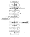
図4は、エンジン始動時における噴射時期制御処理の手順を示すフローチャートであり、本処理はECU40により所定時間ごとに繰り返し実施される。
FIG. 4 is a flowchart showing the procedure of the injection timing control process when the engine is started. This process is repeatedly performed by the
図4において、ステップS11では、濃度センサ30の検出値に基づいて燃料のアルコール濃度を算出するとともに、水温センサ38の検出値に基づいてエンジン水温を算出する。その後、ステップS12では、アルコール濃度とエンジン水温とに基づいて、噴射終了時期制御の実施条件が成立しているか否かを判定する。このとき、例えば、アルコール濃度が30%以上であり、かつエンジン水温が15℃以下であれば、噴射終了時期制御の実施条件が成立していると判定する。
In FIG. 4, in step S <b> 11, the fuel alcohol concentration is calculated based on the detection value of the
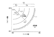
ステップS12では、図5の関係に基づいて噴射終了時期制御の実施条件が成立しているか否かを判定することが可能である。図5では、アルコール濃度とエンジン水温とをパラメータとするマップにおいて、通常制御の実施領域R1と、噴射終了時期制御の実施領域R2とが定められており、それら両実施領域R1,R2を区切る境界が境界線L1となっている。この場合、都度のアルコール濃度とエンジン水温とが実施領域R2に入っていればステップS12が肯定され、実施領域R1に入っていればステップS12が否定される。なお、図5の関係によれば、アルコール濃度が、エンジン水温ごとに定められる所定濃度以上であること、又はエンジン水温が、アルコール濃度ごとに定められる所定温度以下であることが判定されることとなる。 In step S12, it is possible to determine whether or not the conditions for performing the injection end timing control are satisfied based on the relationship of FIG. In FIG. 5, a normal control execution region R1 and an injection end timing control execution region R2 are defined in a map using the alcohol concentration and the engine water temperature as parameters, and a boundary that separates both the execution regions R1 and R2 Is the boundary line L1. In this case, step S12 is affirmed if the respective alcohol concentration and engine water temperature are in the execution region R2, and step S12 is negative if it is in the execution region R1. According to the relationship of FIG. 5, it is determined that the alcohol concentration is equal to or higher than a predetermined concentration determined for each engine water temperature, or that the engine water temperature is equal to or lower than a predetermined temperature determined for each alcohol concentration. Become.
ステップS12がNOの場合(図5の実施領域R1になっている場合)、ステップS13に進み、通常の噴射時期制御を実施する。この通常制御では、例えばあらかじめ定められた所定の噴射開始時期とその時の燃料噴射量とに基づいて噴射信号を生成し、その噴射信号によりインジェクタ21を駆動する。この場合、噴射開始時期を所定時期とした「噴射開始時期制御」が実施される。
When step S12 is NO (when it is the implementation area | region R1 of FIG. 5), it progresses to step S13 and implements normal injection timing control. In this normal control, for example, an injection signal is generated based on a predetermined injection start timing determined in advance and the fuel injection amount at that time, and the
また、ステップS12がYESの場合(図5の実施領域R2になっている場合)にはステップS14に進む。ステップS14では、エンジン10の始動開始後において噴射終了時期制御を実施する期間である始動期間のうち、エンジン初爆後の期間である制御期間Tstを設定する。つまり、噴射開始時期制御が実施される場合、当該制御はエンジン10の始動開始後に直ちに開始される。かかる場合に、エンジン始動装置としてのスタータによる始動開始後においてエンジン10の初爆が生じてから噴射終了時期制御の終了までの期間が「制御期間Tst」である。 If step S12 is YES (if it is the implementation region R2 in FIG. 5), the process proceeds to step S14. In step S14, a control period Tst that is a period after the first engine explosion is set in a start period that is a period in which the injection end timing control is performed after the engine 10 is started. That is, when the injection start timing control is performed, the control is started immediately after the engine 10 is started. In such a case, the period from the start of the first explosion of the engine 10 to the end of the injection end timing control after the start by the starter as the engine starter is the “control period Tst”.
なお本実施形態では、エンジン10の始動開始後に噴射終了時期制御を実施する期間である始動期間において、初爆までの期間と初爆後の期間とのうち後者の期間を制御期間Tstとして設定するようにしている。これは、初爆までの期間が、燃焼に伴うエンジン10の暖機(シリンダブロック等、エンジン本体の受熱)が生じておらず燃料の気化促進に寄与しないためである。ただし、初爆までの期間を含む期間(初爆までの期間+初爆後の期間)を制御期間Tstとして設定することも可能である。この場合には、「始動期間=制御期間Tst」となる。 In this embodiment, in the start-up period, which is a period in which the injection end timing control is performed after the start of the engine 10, the latter period of the period until the first explosion and the period after the first explosion is set as the control period Tst. I am doing so. This is because during the period until the first explosion, the engine 10 is not warmed up due to combustion (heat reception of the engine body such as a cylinder block) and does not contribute to the promotion of fuel vaporization. However, a period including the period until the first explosion (the period until the first explosion + the period after the first explosion) can also be set as the control period Tst. In this case, “starting period = control period Tst”.
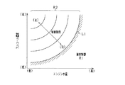
ここでは、図6の関係を用いて制御期間Tstを設定する。図6では、アルコール濃度とエンジン水温とをパラメータとするマップにおいて、図5と同様の噴射終了時期制御の実施領域R2が定められており、その実施領域R2において制御期間Tstが可変に設定される。具体的には、アルコール濃度が高濃度であるほど、又はエンジン水温が低温であるほど、制御期間Tstとして長い期間が設定される。 Here, the control period Tst is set using the relationship of FIG. In FIG. 6, in the map using the alcohol concentration and the engine water temperature as parameters, an execution region R2 of injection end timing control similar to that in FIG. 5 is defined, and the control period Tst is variably set in the execution region R2. . Specifically, a longer period is set as the control period Tst as the alcohol concentration is higher or the engine water temperature is lower.
その後、ステップS15では、今現在が、制御期間Tstであるか否かを判定する。そして、制御期間TstであればステップS16に進み、制御期間TstでなければステップS13に進む(ステップS13は上記説明済み)。なお、制御期間Tstが初爆後の期間として設定されている場合には、エンジン回転速度(エンジン回転速度の上昇変化)によりエンジン10の初爆の発生を検出し、その初爆検出時を起点として制御期間Tstの判定を実施するとよい。そして、ステップS16以降においては、圧縮行程噴射とし、かつ点火時期を基準として噴射終了時期を制御する、噴射終了時期制御を実施する。 Thereafter, in step S15, it is determined whether or not the present time is the control period Tst. If it is the control period Tst, the process proceeds to step S16, and if it is not the control period Tst, the process proceeds to step S13 (step S13 has been described above). When the control period Tst is set as the period after the first explosion, the occurrence of the first explosion of the engine 10 is detected based on the engine rotation speed (an increase in the engine rotation speed), and the time when the first explosion is detected is the starting point. The control period Tst may be determined. In step S16 and subsequent steps, injection end timing control is performed in which the compression stroke injection is performed and the injection end timing is controlled based on the ignition timing.
ステップS16では、既に噴射終了時期制御が実施されているか否かを判定する。そして、ステップS16がNOであればステップS17に進み、噴射終了時期制御を実施する制御モードへの切替を実施する。 In step S16, it is determined whether injection end timing control has already been performed. And if step S16 is NO, it will progress to step S17 and will switch to the control mode which implements injection end timing control.
その後、ステップS18では、今回の点火時期と燃料噴射量とを読み込む。点火時期は、図示しない別処理にて算出され、上述のとおりエンジン水温に基づいて、又はエンジン負荷やエンジン回転速度に基づいて算出されるようになっている。また、燃料噴射量は、上述のとおりエンジン負荷やエンジン回転速度に基づいて算出されるようになっている。 Thereafter, in step S18, the current ignition timing and the fuel injection amount are read. The ignition timing is calculated by a separate process (not shown), and is calculated based on the engine water temperature as described above, or based on the engine load and engine speed. Further, the fuel injection amount is calculated based on the engine load and the engine speed as described above.
その後、ステップS19では、アルコール濃度とエンジン水温とに基づいて、噴射終了時期と点火時期との間の点火余裕角度Aiを設定する。ここでは、図5の関係を用いて点火余裕角度Aiを設定する。図5によれば、噴射終了時期制御の実施領域R2において点火余裕角度Aiが可変に設定される。この場合、アルコール濃度が高濃度であるほど、又はエンジン水温が低温であるほど、噴射終了時期の点火時期に対する相対位置が遅角側にシフトするように点火余裕角度Aiが設定されるようになっている。点火余裕角度Aiは、点火時期に対して進角となる範囲と遅角となる範囲とを含む調整範囲で、噴射終了時期を調整可能にするものとなっている。 Thereafter, in step S19, an ignition margin angle Ai between the injection end timing and the ignition timing is set based on the alcohol concentration and the engine water temperature. Here, the ignition margin angle Ai is set using the relationship of FIG. According to FIG. 5, the ignition margin angle Ai is variably set in the execution region R2 of the injection end timing control. In this case, the ignition margin angle Ai is set such that the higher the alcohol concentration is or the lower the engine water temperature is, the more the relative position of the injection end timing to the ignition timing shifts to the retard side. ing. The ignition margin angle Ai is an adjustment range that includes an advance angle range and a retard angle range with respect to the ignition timing, and makes it possible to adjust the injection end timing.
具体的には、噴射終了時期制御の実施領域R2には、噴射終了時期を点火時期に対して進角とするための点火余裕角度Aiを設定する進角設定範囲Raと、噴射終了時期を点火時期に対して遅角とするための点火余裕角度Aiを設定する遅角設定範囲Rbとが設けられている。遅角設定範囲Rbは、進角設定範囲Raよりも、アルコール濃度が高濃度であり、またエンジン水温が低温である領域に定められている。例えば、アルコール濃度が所定の高濃度域(例えば80%以上)にあり、かつエンジン水温が所定の極低温域(例えば0℃以下)にある範囲が、遅角設定範囲Rbとなっている。 Specifically, in the execution region R2 of the injection end timing control, the advance angle setting range Ra for setting the ignition margin angle Ai for making the injection end timing an advance angle with respect to the ignition timing, and the injection end timing are ignited. A retard setting range Rb for setting an ignition margin angle Ai for retarding the timing is provided. The retard setting range Rb is determined in a region where the alcohol concentration is higher than the advance setting range Ra and the engine water temperature is lower. For example, a range in which the alcohol concentration is in a predetermined high concentration region (for example, 80% or more) and the engine water temperature is in a predetermined extremely low temperature region (for example, 0 ° C. or less) is the retardation setting range Rb.
そして、進角設定範囲Raでは、アルコール濃度が高濃度であるほど、又はエンジン水温が低温であるほど、点火余裕角度Aiとして小さい角度が設定される。この場合の点火余裕角度Aiは点火時期に対する進角量である。つまり、進角設定範囲Raの点火余裕角度Aiによれば、燃料のアルコール濃度が高いほど、又はエンジン水温が低いほど、点火時期に対して噴射終了時期が近づけられることとなる。 In the advance angle setting range Ra, a smaller angle is set as the ignition margin angle Ai as the alcohol concentration is higher or the engine water temperature is lower. The ignition margin angle Ai in this case is an advance amount with respect to the ignition timing. That is, according to the ignition margin angle Ai in the advance angle setting range Ra, the higher the alcohol concentration of the fuel or the lower the engine water temperature, the closer the injection end timing is to the ignition timing.
また、遅角設定範囲Rbでは、アルコール濃度が高濃度であるほど、又はエンジン水温が低温であるほど、点火余裕角度Aiとして大きい角度が設定される。この場合の点火余裕角度Aiは点火時期に対する遅角量である。つまり、遅角設定範囲Rbの点火余裕角度Aiによれば、燃料のアルコール濃度が高いほど、又はエンジン水温が低いほど、点火時期に対して噴射終了時期が遠ざけられることとなる。なお、遅角設定範囲Rbでは、アルコール濃度やエンジン水温に関係なく、点火余裕角度Aiとして1つの遅角量(固定値)が定められていてもよい。進角設定範囲Raと遅角設定範囲Rbとの境界(図の境界線L2)では、点火余裕角度Aiはゼロであるとよい。 In the retard angle setting range Rb, a larger angle is set as the ignition margin angle Ai as the alcohol concentration is higher or the engine water temperature is lower. The ignition margin angle Ai in this case is a retard amount with respect to the ignition timing. That is, according to the ignition margin angle Ai of the retard setting range Rb, the higher the alcohol concentration of the fuel or the lower the engine water temperature, the farther the injection end timing is from the ignition timing. In the retard setting range Rb, one retard amount (fixed value) may be determined as the ignition margin angle Ai regardless of the alcohol concentration or the engine water temperature. At the boundary between the advance angle setting range Ra and the retard angle setting range Rb (boundary line L2 in the figure), the ignition margin angle Ai may be zero.
点火余裕角度Aiが可変に設定されることを図7のタイムチャートを用いて説明する。図7では、いずれも点火時期が同一であり、点火余裕角度Aiが各々相違している。図7では、(a)、(b)、(c)、(d)の順にアルコール濃度が高くなり、またエンジン水温が低くなっている。(a)、(b)では、点火時期に対して噴射終了時期が進角側になっており(Ai=進角値)、(c)では、点火時期と噴射終了時期とが一致しており(Ai=0)、(d)では、点火時期に対して噴射終了時期が遅角側になっている(Ai=遅角値)。 The fact that the ignition margin angle Ai is variably set will be described with reference to the time chart of FIG. In FIG. 7, the ignition timings are the same and the ignition margin angles Ai are different from each other. In FIG. 7, the alcohol concentration increases in the order of (a), (b), (c), and (d), and the engine water temperature decreases. In (a) and (b), the injection end timing is on the advance side with respect to the ignition timing (Ai = advance value), and in (c), the ignition timing and the injection end timing coincide with each other. In (Ai = 0) and (d), the injection end timing is retarded with respect to the ignition timing (Ai = retard value).
点火時期に対して噴射終了時期が遅角側に設定される場合について言及すると、かかる場合には、燃焼室23内において燃料噴霧の流れの勢い(流速)が比較的大きい時点で着火を行うことができ、燃焼室23内における燃焼の拡散を促すことができる。つまり、勢いのある燃料噴霧に対して直接着火を行うことができ、その燃料噴霧の流れの勢いを利用して、燃焼室23内における燃焼の拡散を促すことができる。
Referring to the case where the injection end timing is set to the retard side with respect to the ignition timing, in such a case, ignition is performed at a time when the fuel spray flow momentum (flow velocity) is relatively large. And the diffusion of combustion in the
その後、ステップS20では、上記の点火余裕角度Aiを用い、噴射終了時期を点火時期を基準として設定する。続くステップS21では、ステップS20で設定した噴射終了時期と今回の燃料噴射量とに基づいて噴射開始時期を決定するとともに、それら噴射開始時期と噴射終了時期とにより噴射信号を生成し、その噴射信号を出力する。この噴射信号によりインジェクタ21が駆動される。
Thereafter, in step S20, the ignition margin angle Ai is used to set the injection end timing with reference to the ignition timing. In the subsequent step S21, the injection start timing is determined based on the injection end timing set in step S20 and the current fuel injection amount, and an injection signal is generated based on the injection start timing and the injection end timing. Is output. The
図8は、エンジン始動時におけるエンジン回転速度の推移を示すタイムチャートである。図8において(a)は、低アルコール濃度でかつエンジン水温が高温である場合、すなわち通常の噴射時期制御が実施される場合の回転速度変化を示し、(b)は、高アルコール濃度でかつエンジン水温が低温である場合、すなわち噴射終了時期制御が実施される場合の回転速度変化を示している。 FIG. 8 is a time chart showing changes in engine rotation speed at the time of engine start. In FIG. 8, (a) shows the rotational speed change when the alcohol concentration is low and the engine water temperature is high, that is, when normal injection timing control is performed, and (b) shows the high alcohol concentration and the engine. A change in the rotation speed when the water temperature is low, that is, when the injection end timing control is performed is shown.
図8では、タイミングt31でスタータによるクランキングが開始され、その後、タイミングt32ではエンジン10の初爆によりエンジン回転速度が上昇する。この場合、エンジン回転速度は一旦、アイドル回転速度以上に上昇し、その後、アイドル回転速度で安定する。図8(b)の場合は、(a)に比べて燃料気化が生じにくい状況であるため、初爆後の回転速度の上昇がなだらかであるものの、上述の噴射終了時期制御を実施することで、エンジン始動を実現できるものとなっている。図中のt31〜t33が噴射終了時期制御を実施する期間(始動期間)であり、t32〜t33が制御期間Tstである。制御期間Tstは例えば1〜2秒程度である。 In FIG. 8, cranking by the starter is started at timing t31, and thereafter, at timing t32, the engine speed increases due to the initial explosion of the engine 10. In this case, the engine rotational speed once rises above the idle rotational speed and then stabilizes at the idle rotational speed. In the case of FIG. 8B, since the fuel vaporization is less likely to occur than in FIG. 8A, the increase in the rotational speed after the initial explosion is gentle, but the above-described injection end timing control is performed. The engine can be started. In the figure, t31 to t33 are periods (starting periods) for performing the injection end timing control, and t32 to t33 are the control period Tst. The control period Tst is, for example, about 1 to 2 seconds.
以上詳述した本実施形態によれば、以下の優れた効果が得られる。 According to the embodiment described in detail above, the following excellent effects can be obtained.
エンジン始動時において、燃料のアルコール濃度が高濃度であり、かつエンジン10が低温状態にある場合に、圧縮行程噴射とし、かつその噴射終了時期を点火時期を基準にして制御するようにした。これにより、高アルコール濃度又は低温環境下であっても、燃料噴霧の中での火種(拡散前の火種)を確保することで着火性の向上を実現できる。その結果、アルコール含有燃料を用いたエンジン始動時においてそのエンジン10の始動性を向上させることができる。 When the engine is started, when the alcohol concentration of the fuel is high and the engine 10 is in a low temperature state, the compression stroke injection is performed and the injection end timing is controlled based on the ignition timing. Thereby, even in a high alcohol concentration or low temperature environment, it is possible to improve the ignitability by ensuring the fire type (fire type before diffusion) in the fuel spray. As a result, the startability of the engine 10 can be improved at the time of engine start using the alcohol-containing fuel.
また、噴射終了時期を点火時期を基準にして設定するとともに、その噴射終了時期を基準にして、インジェクタ21を駆動させるための噴射信号を生成するようにした。本構成は、噴射終了時期を先に決定し、その噴射終了時期を基準にして噴射開始時期を決定する構成であり、その逆に噴射開始時期を先に決定し、その噴射開始時期を基準にして噴射終了時期を決定する構成に比べて、点火時期に対する噴射終了時期の間隔(点火余裕角度Ai)のロバスト性を向上させることができる。したがって、点火時期が変更されるとしても、噴射後の燃料噴霧と点火火花との位置関係を適正状態で維持できる。また、エンジン10の回転ばらつきやバッテリ電圧の変動等を想定しても、その影響を最小限に抑え、エンジン始動時のロバスト性を確保することが可能となる。
In addition, the injection end timing is set based on the ignition timing, and an injection signal for driving the
アルコール濃度が高濃度であるほど、又はエンジン水温が低温であるほど、噴射終了時期の点火時期に対する相対位置が遅角側にシフトするよう噴射終了時期を制御するようにした(図7参照)。この場合、燃料のアルコール濃度が高いほど、又はエンジン水温が低いほど、燃料がより気化しにくくなるが、こうした状況下にあっても燃料に対する着火の確からしさを維持することができる。 The injection end timing is controlled so that the relative position of the injection end timing to the ignition timing shifts to the retard side as the alcohol concentration is higher or the engine water temperature is lower (see FIG. 7). In this case, the higher the alcohol concentration of the fuel or the lower the engine water temperature, the more difficult the fuel is vaporized. However, the likelihood of ignition of the fuel can be maintained even under such circumstances.
噴射終了時期を、点火プラグ34の点火時期に対して進角となる範囲だけでなく、遅角となる範囲を含めて調整可能とした。この場合、燃焼室23内において燃料噴霧の流れの勢い(流速)が比較的大きい時点で着火を行うことができ、燃焼室23内における燃焼の拡散を促すことができる。
The injection end timing can be adjusted not only in the range that is advanced with respect to the ignition timing of the spark plug 34 but also in the range that is retarded. In this case, ignition can be performed when the momentum (velocity) of the flow of fuel spray in the
アルコール濃度が所定の高濃度域(80%以上)にあり、かつエンジン水温が所定の極低温域(0℃以下)にある場合に、点火時期に対して遅角となるようにして噴射終了時期を制御するようにした。これにより、燃料が極めて気化しにくい状態下にあっても着火性能を確保できる。 When the alcohol concentration is in a predetermined high concentration region (80% or more) and the engine water temperature is in a predetermined extremely low temperature region (0 ° C. or less), the injection end timing is set to be retarded with respect to the ignition timing. To control. As a result, the ignition performance can be ensured even under conditions where the fuel is extremely difficult to vaporize.
アルコール濃度とエンジン水温とに基づいて、噴射終了時期制御を実施する期間(制御期間Tst)を可変に設定する構成とした。つまり、エンジン始動時において、燃料のアルコール濃度やエンジン水温が都度異なっていると、その始動開始後において始動性低下が生じる期間の長さが相違すると考えられる。この点、上記のとおり噴射終了時期制御を実施する期間(制御期間Tst)の長さを可変に設定することにより、アルコール濃度やエンジン水温が異なる状況下にあっても燃料に対する着火の確からしさを維持することができる。 Based on the alcohol concentration and the engine water temperature, the period for performing the injection end timing control (control period Tst) is variably set. That is, when the engine starts, if the alcohol concentration of the fuel and the engine water temperature are different each time, it is considered that the length of the period in which the startability is reduced after the start of the engine is different. In this respect, by setting the length of the period (control period Tst) during which the injection end timing control is performed as described above, it is possible to increase the likelihood of ignition of fuel even under different conditions of alcohol concentration and engine water temperature. Can be maintained.
燃料のアルコール濃度が高いほど、又はエンジン水温が低いほど、噴射終了時期制御を実施する期間(制御期間Tst)を長い期間にする構成とした。この場合、燃料のアルコール濃度が高いと、又はエンジン水温が低いと、燃料がより気化しにくくなる。また、エンジン10の低温時にはシリンダ壁面温度が低いことも、燃料気化を阻害する要因となっている。この点、上記構成によれば、燃料が気化しにくい状況下にあっても燃料に対する着火の確からしさを維持することができる。 The higher the alcohol concentration of the fuel or the lower the engine water temperature, the longer the period (control period Tst) for carrying out the injection end timing control. In this case, if the alcohol concentration of the fuel is high or the engine water temperature is low, the fuel is more difficult to vaporize. In addition, the cylinder wall surface temperature is low when the temperature of the engine 10 is low, which is a factor that hinders fuel vaporization. In this regard, according to the above configuration, it is possible to maintain the certainty of ignition of the fuel even in a situation where the fuel is difficult to vaporize.
アルコール濃度及びエンジン水温が噴射終了時期制御の実施領域(図5のR2)にない場合に通常制御として噴射開始時期制御を実施し、アルコール濃度及びエンジン水温が噴射終了時期制御の実施領域(図5のR2)にある場合に噴射終了時期制御を実施する構成とした。この場合、噴射開始時期制御と噴射終了時期制御との使い分けにより燃料噴射制御を好適に実施できる。 When the alcohol concentration and the engine water temperature are not in the execution region of the injection end timing control (R2 in FIG. 5), the injection start timing control is performed as normal control, and the alcohol concentration and the engine water temperature are in the execution region of the injection end timing control (FIG. 5). In the case of R2), the injection end timing control is performed. In this case, the fuel injection control can be suitably performed by properly using the injection start timing control and the injection end timing control.
(他の実施形態)
上記実施形態を例えば次のように変更してもよい。
(Other embodiments)
You may change the said embodiment as follows, for example.
・上記実施形態では、燃料のアルコール濃度が所定濃度以上であること、及びエンジン水温が所定温度以下であることよりなる実施条件の成否を判定し、その実施条件が成立する場合に「噴射終了時期制御」を実施する構成としたが、これを以下のように変更してもよい。例えば、
(1)燃料のアルコール濃度が所定濃度以上である場合に、エンジン水温に関係なく「噴射終了時期制御」を実施する構成、
(2)エンジン水温が所定温度以下である場合に、アルコール濃度に関係なく「噴射終了時期制御」を実施する構成、
のいずれかであってもよい。なお上記(2)では、少なくともアルコール含有燃料の使用中であることが判定された状態で「噴射終了時期制御」を実施するとよい。アルコール含有燃料の使用中であることは、例えばアルコール含有燃料が給油されたことを示す給油情報をECU40が認識し、その給油情報から判定されるとよい。
In the above embodiment, it is determined whether or not the execution condition consisting of the alcohol concentration of the fuel being equal to or higher than the predetermined concentration and the engine water temperature being equal to or lower than the predetermined temperature is satisfied. The control is implemented, but this may be changed as follows. For example,
(1) A configuration that performs “injection end timing control” regardless of the engine water temperature when the alcohol concentration of the fuel is equal to or higher than a predetermined concentration;
(2) A configuration that performs “injection end timing control” regardless of the alcohol concentration when the engine water temperature is equal to or lower than a predetermined temperature;
Any of these may be sufficient. In the above (2), “injection end timing control” may be performed in a state where it is determined that at least the alcohol-containing fuel is being used. The fact that the alcohol-containing fuel is being used may be determined from the fuel supply information by the
・上記実施形態では、アルコール濃度とエンジン水温とに基づいて始動期間(制御期間Tst)を可変に設定する構成としたが、これを変更し、アルコール濃度のみに基づいて始動期間を可変に設定する構成、又はエンジン水温のみに基づいて始動期間を可変に設定する構成であってもよい。また、アルコール濃度について、始動期間を可変に設定する領域と固定とする領域とを定めておいてもよい。エンジン水温についても同様である。
また、始動期間(制御期間Tst)を、エンジン回転速度に基づいて可変に設定する構成としてもよい。この場合、エンジン始動時におけるエンジン回転速度の上昇変化に合わせて始動期間の終了のタイミングを変えるとよい。例えば、エンジン回転速度の上昇変化が早いほど、始動期間の終了のタイミングを早くする。
In the above embodiment, the start period (control period Tst) is variably set based on the alcohol concentration and the engine water temperature. However, this is changed and the start period is variably set based only on the alcohol concentration. The structure which sets a starting period variably based only on a structure or engine water temperature may be sufficient. Moreover, you may determine the area | region which sets a starting period variably, and the area | region made fixed about alcohol concentration. The same applies to the engine water temperature.
Further, the start period (control period Tst) may be variably set based on the engine speed. In this case, it is preferable to change the timing of the end of the start period in accordance with the increase in the engine speed at the start of the engine. For example, the faster the engine speed increases, the earlier the end of the start period.
・上記実施形態は、噴射終了時期を、点火時期に対して進角となる範囲と遅角となる範囲とを含む調整範囲で調整可能としたが、これを変更し、噴射終了時期を、点火時期に対して進角となる範囲でのみ調整可能としてもよい。この場合、図5における実施領域R2では、「進角側所定値〜0」が調整範囲とされて、燃料のアルコール濃度が高いほど、又はエンジン水温が低いほど、小さい値(進角量が小さい値)になるようにして点火余裕角度Aiが設定される。 In the above embodiment, the injection end timing can be adjusted within an adjustment range that includes an advance angle range and a retard angle range with respect to the ignition timing. It is good also as adjustment possible only in the range which becomes an advance angle to time. In this case, in the implementation region R2 in FIG. 5, "advanced side predetermined value to 0" is set as the adjustment range, and the smaller the fuel alcohol concentration or the lower the engine water temperature (the smaller the advance amount). Value)), the ignition margin angle Ai is set.
・上記実施形態では、噴射終了時期を点火時期を基準にして設定するとともに、その噴射終了時期を基準にして噴射信号を生成する構成としたが、これを変更し、噴射開始時期を点火時期を基準にして設定するとともに、その噴射開始時期を基準にして噴射信号を生成する構成であってもよい。この場合、噴射開始時期と点火時期との間の間隔が点火余裕角度として設定されるとよい。かかる構成にあっても、噴射終了時期を点火時期を基準にして制御することが可能となっている。 In the above embodiment, the injection end timing is set on the basis of the ignition timing, and the injection signal is generated on the basis of the injection end timing, but this is changed to change the injection start timing to the ignition timing. The configuration may be such that the injection signal is generated based on the injection start timing while being set based on the reference. In this case, the interval between the injection start timing and the ignition timing may be set as the ignition margin angle. Even in such a configuration, the injection end timing can be controlled based on the ignition timing.
・燃料のアルコール濃度は、センサによる検出以外に、推定演算により求められてもよい。例えば、燃料のアルコール濃度が異なると、同じ燃料量であっても、空燃比やエンジントルクが相違することから、空燃比やエンジントルクに基づいてアルコール濃度を推定する。また、エンジン水温も同様に、センサによる検出以外に、推定演算により求められてもよい。例えば、外気温に基づいてエンジン水温(実際にはエンジン始動時水温)を推定する。 -The alcohol concentration of the fuel may be obtained by estimation calculation other than detection by a sensor. For example, if the alcohol concentration of the fuel is different, the air-fuel ratio and the engine torque are different even if the fuel amount is the same. Therefore, the alcohol concentration is estimated based on the air-fuel ratio and the engine torque. Similarly, the engine water temperature may be obtained by estimation calculation other than the detection by the sensor. For example, the engine water temperature (actually, the engine start water temperature) is estimated based on the outside air temperature.
10…エンジン(内燃機関)、21…燃料噴射弁、23…燃焼室、34…点火プラグ(点火手段)、40…ECU(判定手段、噴射制御手段)。 DESCRIPTION OF SYMBOLS 10 ... Engine (internal combustion engine), 21 ... Fuel injection valve, 23 ... Combustion chamber, 34 ... Spark plug (ignition means), 40 ... ECU (determination means, injection control means).
Claims (7)
前記燃料噴射弁に供給される燃料のアルコール濃度が所定濃度以上であること、及び前記内燃機関の温度が所定温度以下であることの少なくともいずれかを含む実施条件の成否を判定する判定手段と、
前記実施条件が成立する場合に、前記内燃機関の始動開始からの所定の始動期間において、前記燃料噴射弁の燃料噴射を前記内燃機関の圧縮行程で実施し、かつその噴射終了時期を前記点火手段の点火時期を基準にして制御する噴射制御手段と、
を備えていることを特徴とする内燃機関の燃料噴射制御装置。 In a fuel injection control device applied to a spark ignition type internal combustion engine comprising a fuel injection valve (21) for in-cylinder injection and an ignition means (34) for generating an ignition spark in a combustion chamber (23),
Determination means for determining success or failure of an implementation condition including at least one of an alcohol concentration of fuel supplied to the fuel injection valve being a predetermined concentration or higher and a temperature of the internal combustion engine being a predetermined temperature or lower;
When the execution condition is satisfied, the fuel injection of the fuel injection valve is performed in the compression stroke of the internal combustion engine in a predetermined start period from the start of the internal combustion engine, and the injection end timing is set to the ignition means. Injection control means for controlling the ignition timing of
A fuel injection control device for an internal combustion engine, comprising:
Priority Applications (3)
| Application Number | Priority Date | Filing Date | Title |
|---|---|---|---|
| JP2013051531A JP2014177882A (en) | 2013-03-14 | 2013-03-14 | Fuel injection control device of internal combustion engine |
| BR102014005762-5A BR102014005762B1 (en) | 2013-03-14 | 2014-03-12 | APPARATUS FOR FUEL INJECTION CONTROL |
| US14/211,647 US20140261300A1 (en) | 2013-03-14 | 2014-03-14 | Fuel injection control apparatus for internal combustion engine |
Applications Claiming Priority (1)
| Application Number | Priority Date | Filing Date | Title |
|---|---|---|---|
| JP2013051531A JP2014177882A (en) | 2013-03-14 | 2013-03-14 | Fuel injection control device of internal combustion engine |
Publications (1)
| Publication Number | Publication Date |
|---|---|
| JP2014177882A true JP2014177882A (en) | 2014-09-25 |
Family
ID=51521699
Family Applications (1)
| Application Number | Title | Priority Date | Filing Date |
|---|---|---|---|
| JP2013051531A Pending JP2014177882A (en) | 2013-03-14 | 2013-03-14 | Fuel injection control device of internal combustion engine |
Country Status (3)
| Country | Link |
|---|---|
| US (1) | US20140261300A1 (en) |
| JP (1) | JP2014177882A (en) |
| BR (1) | BR102014005762B1 (en) |
Cited By (1)
| Publication number | Priority date | Publication date | Assignee | Title |
|---|---|---|---|---|
| WO2019017060A1 (en) * | 2017-07-18 | 2019-01-24 | 本田技研工業株式会社 | Control device for internal combustion engine |
Families Citing this family (1)
| Publication number | Priority date | Publication date | Assignee | Title |
|---|---|---|---|---|
| CN112324583B (en) * | 2020-11-05 | 2022-08-23 | 潍柴动力股份有限公司 | Cold-start warm-up control method and device |
-
2013
- 2013-03-14 JP JP2013051531A patent/JP2014177882A/en active Pending
-
2014
- 2014-03-12 BR BR102014005762-5A patent/BR102014005762B1/en active IP Right Grant
- 2014-03-14 US US14/211,647 patent/US20140261300A1/en not_active Abandoned
Cited By (1)
| Publication number | Priority date | Publication date | Assignee | Title |
|---|---|---|---|---|
| WO2019017060A1 (en) * | 2017-07-18 | 2019-01-24 | 本田技研工業株式会社 | Control device for internal combustion engine |
Also Published As
| Publication number | Publication date |
|---|---|
| BR102014005762A2 (en) | 2015-06-23 |
| BR102014005762B1 (en) | 2021-06-01 |
| US20140261300A1 (en) | 2014-09-18 |
Similar Documents
| Publication | Publication Date | Title |
|---|---|---|
| US9382857B2 (en) | Post fuel injection of gaseous fuel to reduce exhaust emissions | |
| JP5786679B2 (en) | Start control device for compression self-ignition engine | |
| JP2002130015A (en) | Fuel injection controller for cylinder injection type internal combustion engine | |
| US9284900B2 (en) | Fuel injection control device for internal combustion engine | |
| US7561957B1 (en) | Spark-ignition direct-injection cold start strategy using high pressure start | |
| US9903332B2 (en) | Control device of multi-cylinder internal combustion engine | |
| JP2015014236A (en) | Control device of cylinder injection engine | |
| US9863389B2 (en) | Control unit for a multi-cylinder internal combustion engine | |
| JP2010065604A (en) | Control device of multi-cylinder engine | |
| JP4135643B2 (en) | Control device for direct-injection spark-ignition internal combustion engine | |
| JP2002130013A (en) | Controller for cylinder injection type internal combustion engine | |
| JP2014218994A (en) | Start control device of internal combustion engine | |
| JP6048296B2 (en) | Engine control device | |
| JP2013213439A (en) | Fuel injection control device | |
| JP2011064109A (en) | Control device for internal combustion engine | |
| JP2014177882A (en) | Fuel injection control device of internal combustion engine | |
| JPWO2013084344A1 (en) | Control device for internal combustion engine | |
| JP2010209859A (en) | Controlling device of internal combustion engine | |
| JP2017166493A (en) | Control device for direct injection engine | |
| JP5831168B2 (en) | Start control device for compression self-ignition engine | |
| JP5790558B2 (en) | Fuel injection control device for internal combustion engine | |
| JP2011236802A (en) | Internal combustion engine control apparatus | |
| JP2011157822A (en) | Fuel injection control device for internal combustion engine | |
| JP2014238079A (en) | Start control device for engine | |
| US11313296B2 (en) | Control device for internal combustion engine |