EP2829690A1 - Ensemble de maintenance pouvant s'adapter à l'intérieur d'un moteur à turbine à gaz - Google Patents
Ensemble de maintenance pouvant s'adapter à l'intérieur d'un moteur à turbine à gaz Download PDFInfo
- Publication number
- EP2829690A1 EP2829690A1 EP13177623.9A EP13177623A EP2829690A1 EP 2829690 A1 EP2829690 A1 EP 2829690A1 EP 13177623 A EP13177623 A EP 13177623A EP 2829690 A1 EP2829690 A1 EP 2829690A1
- Authority
- EP
- European Patent Office
- Prior art keywords
- cavity
- gas turbine
- turbine engine
- maintenance assembly
- platform
- Prior art date
- Legal status (The legal status is an assumption and is not a legal conclusion. Google has not performed a legal analysis and makes no representation as to the accuracy of the status listed.)
- Withdrawn
Links
Images
Classifications
-
- E—FIXED CONSTRUCTIONS
- E04—BUILDING
- E04G—SCAFFOLDING; FORMS; SHUTTERING; BUILDING IMPLEMENTS OR AIDS, OR THEIR USE; HANDLING BUILDING MATERIALS ON THE SITE; REPAIRING, BREAKING-UP OR OTHER WORK ON EXISTING BUILDINGS
- E04G3/00—Scaffolds essentially supported by building constructions, e.g. adjustable in height
- E04G3/24—Scaffolds essentially supported by building constructions, e.g. adjustable in height specially adapted for particular parts of buildings or for buildings of particular shape, e.g. chimney stacks or pylons
-
- F—MECHANICAL ENGINEERING; LIGHTING; HEATING; WEAPONS; BLASTING
- F01—MACHINES OR ENGINES IN GENERAL; ENGINE PLANTS IN GENERAL; STEAM ENGINES
- F01D—NON-POSITIVE DISPLACEMENT MACHINES OR ENGINES, e.g. STEAM TURBINES
- F01D25/00—Component parts, details, or accessories, not provided for in, or of interest apart from, other groups
- F01D25/28—Supporting or mounting arrangements, e.g. for turbine casing
- F01D25/285—Temporary support structures, e.g. for testing, assembling, installing, repairing; Assembly methods using such structures
-
- B—PERFORMING OPERATIONS; TRANSPORTING
- B66—HOISTING; LIFTING; HAULING
- B66F—HOISTING, LIFTING, HAULING OR PUSHING, NOT OTHERWISE PROVIDED FOR, e.g. DEVICES WHICH APPLY A LIFTING OR PUSHING FORCE DIRECTLY TO THE SURFACE OF A LOAD
- B66F3/00—Devices, e.g. jacks, adapted for uninterrupted lifting of loads
- B66F3/24—Devices, e.g. jacks, adapted for uninterrupted lifting of loads fluid-pressure operated
- B66F3/25—Constructional features
- B66F3/35—Inflatable flexible elements, e.g. bellows
-
- E—FIXED CONSTRUCTIONS
- E04—BUILDING
- E04G—SCAFFOLDING; FORMS; SHUTTERING; BUILDING IMPLEMENTS OR AIDS, OR THEIR USE; HANDLING BUILDING MATERIALS ON THE SITE; REPAIRING, BREAKING-UP OR OTHER WORK ON EXISTING BUILDINGS
- E04G3/00—Scaffolds essentially supported by building constructions, e.g. adjustable in height
- E04G3/24—Scaffolds essentially supported by building constructions, e.g. adjustable in height specially adapted for particular parts of buildings or for buildings of particular shape, e.g. chimney stacks or pylons
- E04G3/246—Scaffolds essentially supported by building constructions, e.g. adjustable in height specially adapted for particular parts of buildings or for buildings of particular shape, e.g. chimney stacks or pylons following the inside contour of a building
-
- F—MECHANICAL ENGINEERING; LIGHTING; HEATING; WEAPONS; BLASTING
- F02—COMBUSTION ENGINES; HOT-GAS OR COMBUSTION-PRODUCT ENGINE PLANTS
- F02C—GAS-TURBINE PLANTS; AIR INTAKES FOR JET-PROPULSION PLANTS; CONTROLLING FUEL SUPPLY IN AIR-BREATHING JET-PROPULSION PLANTS
- F02C7/00—Features, components parts, details or accessories, not provided for in, or of interest apart form groups F02C1/00 - F02C6/00; Air intakes for jet-propulsion plants
-
- F—MECHANICAL ENGINEERING; LIGHTING; HEATING; WEAPONS; BLASTING
- F05—INDEXING SCHEMES RELATING TO ENGINES OR PUMPS IN VARIOUS SUBCLASSES OF CLASSES F01-F04
- F05D—INDEXING SCHEME FOR ASPECTS RELATING TO NON-POSITIVE-DISPLACEMENT MACHINES OR ENGINES, GAS-TURBINES OR JET-PROPULSION PLANTS
- F05D2230/00—Manufacture
- F05D2230/60—Assembly methods
- F05D2230/68—Assembly methods using auxiliary equipment for lifting or holding
-
- F—MECHANICAL ENGINEERING; LIGHTING; HEATING; WEAPONS; BLASTING
- F05—INDEXING SCHEMES RELATING TO ENGINES OR PUMPS IN VARIOUS SUBCLASSES OF CLASSES F01-F04
- F05D—INDEXING SCHEME FOR ASPECTS RELATING TO NON-POSITIVE-DISPLACEMENT MACHINES OR ENGINES, GAS-TURBINES OR JET-PROPULSION PLANTS
- F05D2230/00—Manufacture
- F05D2230/72—Maintenance
Definitions
- the present disclosure relates to maintenance activities of gas turbine engines, and, more particularly, to a maintenance assembly being arranged within a gas turbine engine for performing maintenance activities therewithin.
- the present disclosure describes a maintenance assembly adaptable within a gas turbine engine, that will be presented in the following simplified summary to provide a basic understanding of one or more aspects of the disclosure that are intended to overcome the discussed drawbacks, but to include all advantages thereof, along with providing some additional advantages.
- This summary is not an extensive overview of the disclosure. It is intended to neither identify key or critical elements of the disclosure, nor to delineate the scope of the present disclosure. Rather, the sole purpose of this summary is to present some concepts of the disclosure, its aspects and advantages in a simplified form as a prelude to the more detailed description that is presented hereinafter.
- An object of the present disclosure is to describe a maintenance assembly adaptable within gas turbine engines, which may be capable of precluding or minimizing risk of accidents, and associated problems and time involved in carrying and assembling structures every time workers required to perform various activities, such as maintenance, assembling or disassembling within the gas turbine engine.
- Another object of the present disclosure is to describe a maintenance assembly adaptable with gas turbine engine, which is convenient to use in an effective and economical way.
- a maintenance assembly adaptable within a gas turbine engine for workers to perform maintenance activities within the gas turbine engine.
- the maintenance assembly is capable of being arranged within a cavity, generally around a combustor, accessible from a manhole of the gas turbine engine.
- the maintenance assembly includes a platform capable of carrying the workers; and an inflatable member cooperatively configured to the platform. The inflatable member at a normal condition, when placed outside of the cavity of the gas turbine engine, being at a deflated position.
- the inflatable member at a working condition, when arranged within the cavity of the gas turbine engine, being at inflated position so as to accommodate a shape coordinating the cavity in such a manner that the platform is advance within the cavity up to a predetermined level to enable the workers on the platform to reach at a predetermined position within the cavity to perform the maintenance activities within the gas turbine engine.
- the maintenance assembly 100 may include an inflating source adapted to be configured to the inflatable member to inflate the inflatable member.
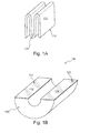
- FIGS. 1A and 1B illustrate examples of a maintenance assembly in deflated and inflated positions, respectively, outside of a gas turbine engine, in accordance with an exemplary embodiment of the present disclosure
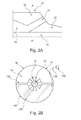
- FIGS. 2A and 2B specifically, FIG. 2A illustrates a side view line representation of a gas turbine engine portion, and FIG. 2B illustrates a cross-sectional view of the gas turbine engine portion along a line A-A' of FIG. 2A , depicting an example maintenance assembly in a working condition within the gas turbine engine portion at a shutdown condition, in accordance with an exemplary embodiment of the present disclosure.
- FIGS. 1A to 2B examples of a maintenance assembly 100 configured to be adaptable within a gas turbine engine 10, are illustrated in accordance with an exemplary embodiment of the present disclosure.
- FIGS. 1A and 1B respectively illustrate an example maintenance assembly in deflated and inflated positions outside of the gas turbine engine 10
- FIGS. 2A and 2B illustrate the maintenance assembly in combination with the gas turbine engine portion at a working condition.
- various associated elements may be well-known to those skilled in the art, it is not deemed necessary for purposes of acquiring an understanding of the present disclosure that there be recited herein all of the constructional details and explanation thereof.
- the maintenance assembly 100 includes a platform 110 and an inflatable member 120.
- the platform 110 and the inflatable member 120 are cooperatively configured to each other.
- the inflatable member 120 is cooperatively configured below of the platform 110.
- the platform 110 may be a one-piece hard structure.
- the platform 110 may be a hard splitable structure. Suitable examples of the one-piece or splitable hard surface structure of the platform 110 from which it may be made include, but not limiting to, woods, laminates etc.
- the inflatable member 120 may be made of a suitable material that is capable of withstanding the pressure and holding medium that may be utilized to inflate thereto.
- the maintenance assembly 100 is capable of being arranged within the gas turbine engine 10 at a shutdown condition for enabling workers to perform maintenance activities therewithin.
- the term maintenance activities includes, but not limiting to, various activities, such as assembly, disassembly or timely and preventive maintenance, that are required to be performed within the gas turbine engine 10 to avoid any unnecessary breakdown or accidents.
- the gas turbine engine 10 as shown in FIGS. 2A and 2B , includes a cavity 12, generally around a combustor 14.
- the combustor 14 is shown around a rotor 18.
- the gas turbine engine 10 is shown to include a typical arrangement depicting a turbine 20 and a compressor 22.
- the cavity 12 is accessible from a manhole 16 of the gas turbine engine 10 for providing the maintenance assembly 100 within the gas turbine engine 10 for enabling the workers to perform maintenance activities within the gas turbine engine.
- the maintenance assembly 100 is provided within the cavity 12 through manhole 14 and required to be inflated.
- An exemplary inflated maintenance assembly 100 outside of the cavity can be seen in FIG. 1B .
- the inflatable member 120 is being inflated to adapt an inflated position. At the inflated position, as shown in FIG.
- the inflatable member 120 accommodates a shape that coordinates the cavity 10 in such a manner that the platform 110 is advance within the cavity 12 up to a predetermined level to enable the workers on the platform 110 to reach at a predetermined position within the cavity 12 to perform the maintenance activities within the gas turbine engine 10.
- the platform 110 is adapted to be advanced up to the predetermined position, which may be at least up to a lower half position of the cavity 12.
- the platform 110 is adapted to be advanced by the inflatable member 120. Where the platform 110 is the hard splitable structure, it is adapted to be expended and advanced to form a flat and split surface 112 around the combustor 14 of the gas turbine engine 10. Further, where the platform 110 is the one-piece structure, it is adapted to be expended and advanced below the combustor 14 level.
- the maintenance assembly 100 includes an inflating source 130 adapted to be configured to the inflatable member 120 to inflate the inflatable member 120.
- the inflating source 130 may be adapted to be disposed outside of the cavity 12.
- the inflating source 130 from the outside of the cavity 12 is fluidically connected, via a pipe 132, to inflate the inflatable member 120 within the cavity 12.
- the inflatable member 120 may incorporate a socket 122 to connect the pipe 132.
- the inflating source 130 may be a pump of suitable power to pneumatically or hydraulically inflate the inflating source 130.
- the inflating source 130 may be deposed within the cavity 12 for inflating the inflatable member 120.
- the maintenance assembly in combination with the gas turbine engine of the present disclosure is advantageous in various scopes.
- the maintenance assembly a compact and preassembled assembly which may be easily adaptable within the gas turbine engines. This precludes or minimizes the risk of accidents, and associated problems and time involved in carrying and assembling, as required in conventional structures, every time workers are required to perform various activities, such as maintenance, assembling or disassembling within the gas turbine engine. Further, adaptability of the maintenance assembly within the gas turbine engine makes the maintenance activities within the gas turbine engine convenient and effective in economical manner.
Priority Applications (3)
| Application Number | Priority Date | Filing Date | Title |
|---|---|---|---|
| EP13177623.9A EP2829690A1 (fr) | 2013-07-23 | 2013-07-23 | Ensemble de maintenance pouvant s'adapter à l'intérieur d'un moteur à turbine à gaz |
| US14/335,100 US9540829B2 (en) | 2013-07-23 | 2014-07-18 | Maintenance assembly adaptable within gas turbine engine |
| CN201410351732.5A CN104343540B (zh) | 2013-07-23 | 2014-07-23 | 可适用于燃气涡轮发动机内的维护组件 |
Applications Claiming Priority (1)
| Application Number | Priority Date | Filing Date | Title |
|---|---|---|---|
| EP13177623.9A EP2829690A1 (fr) | 2013-07-23 | 2013-07-23 | Ensemble de maintenance pouvant s'adapter à l'intérieur d'un moteur à turbine à gaz |
Publications (1)
| Publication Number | Publication Date |
|---|---|
| EP2829690A1 true EP2829690A1 (fr) | 2015-01-28 |
Family
ID=48856526
Family Applications (1)
| Application Number | Title | Priority Date | Filing Date |
|---|---|---|---|
| EP13177623.9A Withdrawn EP2829690A1 (fr) | 2013-07-23 | 2013-07-23 | Ensemble de maintenance pouvant s'adapter à l'intérieur d'un moteur à turbine à gaz |
Country Status (3)
| Country | Link |
|---|---|
| US (1) | US9540829B2 (fr) |
| EP (1) | EP2829690A1 (fr) |
| CN (1) | CN104343540B (fr) |
Families Citing this family (3)
| Publication number | Priority date | Publication date | Assignee | Title |
|---|---|---|---|---|
| US20160069094A1 (en) * | 2006-08-05 | 2016-03-10 | Donald F. Lombardi | Mason's adjustable chimney-platform arrangement |
| US10378222B1 (en) * | 2017-03-14 | 2019-08-13 | Hicham Elanmati | Inflatable scaffolding |
| CN113792503B (zh) * | 2021-09-15 | 2024-04-02 | 中国船舶重工集团公司第七0三研究所 | 一种船用燃气轮机低压压气机低工况级间放气防喘方法 |
Citations (3)
| Publication number | Priority date | Publication date | Assignee | Title |
|---|---|---|---|---|
| US3279192A (en) * | 1963-12-30 | 1966-10-18 | Gen Electric | Variable area exhaust nozzle |
| US3323307A (en) * | 1966-01-26 | 1967-06-06 | Lockheed Aircraft Corp | Turbofan jet engine tool |
| US4199301A (en) * | 1976-08-13 | 1980-04-22 | Bbc Brown Boveri & Company Limited | Housing for thermal apparatus and fluid flow machines particularly a steam turbine |
Family Cites Families (64)
| Publication number | Priority date | Publication date | Assignee | Title |
|---|---|---|---|---|
| US2361832A (en) * | 1941-10-31 | 1944-10-31 | Eyles George Frederick | Fluid pressure lifting means |
| US2609177A (en) * | 1948-12-15 | 1952-09-02 | George E Hughes | Automobile jack |
| USRE24272E (en) * | 1952-01-07 | 1957-02-12 | Land vehicle or load-moving device comprising | |
| US3799504A (en) * | 1972-05-02 | 1974-03-26 | J Vaughen | Pneumatically operated lift device |
| US3840922A (en) * | 1972-11-03 | 1974-10-15 | Thermo Flex Inc | Landing cushion for falling objects |
| US3948344A (en) * | 1974-10-03 | 1976-04-06 | Johnson Raynor A | Low cost planar air pallet material handling system |
| DE7533295U (de) * | 1975-10-20 | 1976-02-26 | Vetter, Manfred, 5352 Zuelpich | Hebekissen zum heben, stuetzen und verschieben von lasten |
| GB1604141A (en) * | 1978-01-05 | 1981-12-02 | Modern Precision Engs & Associ | Air cushion lifting device |
| US4470578A (en) * | 1979-03-30 | 1984-09-11 | Idux Industriell Exploatering Aktiebolag | Load transfer device |
| US4372533A (en) * | 1980-05-19 | 1983-02-08 | Goodyear Aerospace Corporation | Pneumatic lift pad |
| IT1142775B (it) * | 1981-05-22 | 1986-10-15 | Alitalia Spa | Posizionatore idro-pneumatico per il cambio di motori alari di velivoli a simili |
| GB2106183B (en) * | 1981-09-19 | 1986-04-03 | Peter Selwyn Kerton | Animal lifting device |
| GB8323675D0 (en) * | 1983-09-03 | 1983-10-05 | Snell T B | Lifting devices |
| US4678157A (en) * | 1984-08-30 | 1987-07-07 | Robert Fondiller | Apparatus for the construction of a low cost structure |
| US4746471A (en) * | 1984-11-14 | 1988-05-24 | Hale Loren E | Method of constructing a reinforced concrete structure |
| US4629162A (en) * | 1985-05-02 | 1986-12-16 | Porche Albert J | Pneumatic invalid lift |
| DE3516676A1 (de) * | 1985-05-09 | 1986-11-20 | Deutsche Schlauchbootfabrik Hans Scheibert GmbH & Co KG, 3456 Eschershausen | Sprungrettungsgeraet |
| US4712335A (en) * | 1986-12-17 | 1987-12-15 | Barkdull Jr Howard L | Method of span construction |
| US4865096A (en) * | 1988-08-16 | 1989-09-12 | American Fuel Cell And Coated Fabrics Company | Lightweight pillow tank |
| IT1229892B (it) * | 1989-02-16 | 1991-09-13 | Pirelli | Dispositivo d'emergenza per consentire il trasferimento di una pluralita' di persone fra due zone distanti fra loro |
| JPH086455B2 (ja) * | 1989-02-20 | 1996-01-24 | 株式会社フジタ | 筒状構造体内部の作業用足場構造 |
| DE8914694U1 (fr) * | 1989-12-14 | 1990-04-19 | Vetter, Manfred, 5352 Zuelpich, De | |
| NO311989B1 (no) * | 1990-11-05 | 2002-02-25 | Audun Haugs | Anordning ved strekkorgan |
| IL96825A0 (en) * | 1990-12-30 | 1991-09-16 | Pavie Henry | Inflatable construction apparatus |
| US5131503A (en) * | 1991-01-29 | 1992-07-21 | Billington Welding & Manufacturing, Inc. | Vertically adjustable work station assembly |
| US5119907A (en) * | 1991-01-29 | 1992-06-09 | Billington Welding & Manufacturing, Inc. | Vertically adjustable work station assembly |
| DE69212819T2 (de) * | 1991-02-12 | 1997-03-06 | Void Formers Ltd | Aufbaumethode und -vorrichtung |
| ZA935564B (en) * | 1992-08-06 | 1994-03-02 | De Beers Ind Diamond | Formwork apparatus |
| DE4227094C2 (de) * | 1992-08-17 | 2001-02-08 | Man Technologie Gmbh | Pneumatische Bodenstütze für verlegbare Brücken |
| US5785148A (en) * | 1993-12-27 | 1998-07-28 | Wildner; Robert J. | Environmentally safe work platform with buoyancy system |
| US5522181A (en) * | 1994-05-26 | 1996-06-04 | Ellsworth; Thayne N. | Devices for the rapid deployment of igloos |
| DE9418076U1 (de) * | 1994-11-11 | 1995-01-12 | Festo Kg | Tragwerk für die Bautechnik |
| US5542806A (en) * | 1995-03-31 | 1996-08-06 | The Champion Company | Fluid actuated lifting and tilting device |
| US5668421A (en) * | 1995-04-06 | 1997-09-16 | E. B. Eddy Forest Products Ltd. | Pressurized air-gap guided active linear motor suspension system |
| US6082743A (en) * | 1995-12-11 | 2000-07-04 | Tp-Jac, Inc. | Method of leveling a recreational vehicle |
| GB9613077D0 (en) * | 1996-06-21 | 1996-08-28 | Mangar International Ltd | Pneumatically inflatable lifting devices and valve assemblies for lifting such devices |
| US5931248A (en) * | 1997-09-15 | 1999-08-03 | The United States Of America As Represented By The Secretary Of The Navy | Durable roll-stabilizing keel system for hovercraft |
| US6176113B1 (en) * | 1999-02-19 | 2001-01-23 | White, Iii Harold J. | Inflatable device for removing dents in components of vehicles |
| US6520449B2 (en) * | 1999-05-21 | 2003-02-18 | Vortex Holding Company | Lifting platform with positive horizontal stability |
| ES2245348T3 (es) * | 2000-03-27 | 2006-01-01 | Airlight Limited (Ag) | Componente neumatico. |
| US6648507B2 (en) * | 2000-04-19 | 2003-11-18 | Gta Containers, Inc. | Collapsible storage tank for liquids |
| US6551091B1 (en) * | 2000-09-14 | 2003-04-22 | The Boeing Company | Flexible inflatable support structure for use with a reusable compaction bag |
| DE50201807D1 (de) * | 2001-07-20 | 2005-01-20 | Prospective Concepts Ag Glattb | Pneumatisches bau- oder brückenelement |
| US20040217338A1 (en) * | 2003-04-30 | 2004-11-04 | Abrahamson Guy A. | Device and method for leveling recreational vehicles |
| US6948590B1 (en) * | 2003-08-21 | 2005-09-27 | Bellsouth Intellectual Property Corporation | Redundant systems utilizing inflatable devices in association with utility structures |
| US20060027276A1 (en) * | 2003-10-20 | 2006-02-09 | Alford Main | Seamless inflatable bag with multiple applications |
| EP1694267A2 (fr) * | 2003-12-17 | 2006-08-30 | DAVIS, David T. | Elevateur pneumatique |
| ITTO20040150A1 (it) * | 2004-03-10 | 2004-06-10 | Torino Politecnico | Attuatore deformabile a fluido a doppio effetto a tre camere |
| WO2006027558A2 (fr) * | 2004-09-04 | 2006-03-16 | Middlegate Marketing Limited | Appareil de manutention, poche gonflable associee, vehicules et remorques integrant des plateformes de chargement amovibles |
| US7328622B2 (en) * | 2005-06-30 | 2008-02-12 | The Boeing Company | Soft support systems and methods for dynamically testing structures |
| US7779540B2 (en) | 2005-08-12 | 2010-08-24 | United Technologies Corporation | Apparatus and method for quadrail ergonomic assembly |
| DE102005047486B4 (de) * | 2005-10-04 | 2007-06-14 | Eisenmann Anlagenbau Gmbh & Co. Kg | Hubtisch |
| US7926787B2 (en) * | 2006-11-21 | 2011-04-19 | Blue Sky Decks, Llc | Elevated platform and method of elevating the same |
| US8702059B2 (en) * | 2006-11-21 | 2014-04-22 | Craig Wieland | Elevated platform and method of elevating the same |
| US7845577B2 (en) * | 2007-08-05 | 2010-12-07 | Pillwtrack Ltd. | Inflatable automative traction recovery device |
| US8413960B2 (en) * | 2009-06-25 | 2013-04-09 | Brent E. Davis | Inflatable equipment stabilizer |
| US8548626B2 (en) * | 2009-09-03 | 2013-10-01 | Irobot Corporation | Method and device for manipulating an object |
| DK2332879T3 (da) * | 2009-12-09 | 2013-03-11 | Vetter Gmbh | Løftepose af bane-formet gummimateriale varm-vulkaniseret i en presse og fremgangsmåde til fremstilling deraf |
| US9056755B1 (en) * | 2010-10-07 | 2015-06-16 | Daniel W. Moy | Compact air compressor and vehicle jack |
| US8322492B1 (en) * | 2011-01-05 | 2012-12-04 | Balzano John F | Ladder system with integrated air bags at base |
| US9228451B2 (en) | 2011-05-03 | 2016-01-05 | Pratt & Whitney Canada Corp. | Gas turbine engine module adapter to a carrier |
| GB2495988A (en) * | 2011-10-28 | 2013-05-01 | Perry Williamson | Expanding support for an excavation |
| US9279260B2 (en) * | 2012-10-12 | 2016-03-08 | Norton Baum | Modular panel concrete form for self-lifting concrete form system |
| US9303794B2 (en) * | 2013-11-11 | 2016-04-05 | James Pirtle | Buried pipeline repair system |
-
2013
- 2013-07-23 EP EP13177623.9A patent/EP2829690A1/fr not_active Withdrawn
-
2014
- 2014-07-18 US US14/335,100 patent/US9540829B2/en not_active Expired - Fee Related
- 2014-07-23 CN CN201410351732.5A patent/CN104343540B/zh not_active Expired - Fee Related
Patent Citations (3)
| Publication number | Priority date | Publication date | Assignee | Title |
|---|---|---|---|---|
| US3279192A (en) * | 1963-12-30 | 1966-10-18 | Gen Electric | Variable area exhaust nozzle |
| US3323307A (en) * | 1966-01-26 | 1967-06-06 | Lockheed Aircraft Corp | Turbofan jet engine tool |
| US4199301A (en) * | 1976-08-13 | 1980-04-22 | Bbc Brown Boveri & Company Limited | Housing for thermal apparatus and fluid flow machines particularly a steam turbine |
Also Published As
| Publication number | Publication date |
|---|---|
| CN104343540B (zh) | 2017-04-12 |
| CN104343540A (zh) | 2015-02-11 |
| US20150027811A1 (en) | 2015-01-29 |
| US9540829B2 (en) | 2017-01-10 |
Similar Documents
| Publication | Publication Date | Title |
|---|---|---|
| EP2584152A3 (fr) | Cadre de turbine intermédiaire (MTF) pour un moteur à turbine à gaz | |
| EP3225779B1 (fr) | Outil d'extraction | |
| WO2015065563A3 (fr) | Liaison pour un carénage dans un cadre de milieu de turbine d'un moteur à turbine à gaz | |
| GB2568143B (en) | Outlet guide vane for turbomachine, comprising a lubricant cooling passage equipped with a thermal conducting matrix compressed between the intrados and | |
| WO2014130103A3 (fr) | Échangeurs de chaleur intégrés pour un réacteur à double flux à engrenages à faible rapport de pression de ventilateur | |
| EP2388435A3 (fr) | Aube rotorique de turbine à plate-forme refroidie | |
| EP2613014A3 (fr) | Étage de moteur à turbine à gaz et procédé associé de modification | |
| EP2354451A3 (fr) | Ensemble de plaque d'étanchéité de turbine | |
| BRPI1006159A2 (pt) | "processo e sistema de monitoramento de fenômenos vibratórios que ocorrem em um motor de turbina a gás de aeronave em funcionamento". | |
| EP2829690A1 (fr) | Ensemble de maintenance pouvant s'adapter à l'intérieur d'un moteur à turbine à gaz | |
| EP2108786A3 (fr) | Agencement de soufflante de moteur aéronautique | |
| EP2826708A3 (fr) | Pale d'éolienne avec des caractéristques spéciales de la surface | |
| EP2796668A3 (fr) | Section de carter d'un étage de compresseur ou de turbine d'une turbomachine | |
| WO2011117560A3 (fr) | Tube de degazage d'un turboreacteur, procede de montage d'un tel tube et turboreacteur avec un tel tube | |
| EP2395202A3 (fr) | Ensemble de montage d'une boite de transmission d'un moteur de turbine à gaz | |
| EP2644836A3 (fr) | Segment d'enveloppe refroidi par effusion avec un revêtement abradable | |
| EP2615244A3 (fr) | Aube de turbine refroidie par couche d'air comportant une pluralité de segments de rainure à la surface extérieure | |
| EP2554795A3 (fr) | Ensemble d'aubes statoriques pour une turbine à gaz | |
| WO2009019153A3 (fr) | Turbocompresseur de suralimentation doté d'un dispositif de refroidissement et d'une amenée d'huile | |
| CN103670719B (zh) | 一种涡轮观察孔密封装置 | |
| EP2511482A3 (fr) | Système de refroidissement d'un segment d'anneau de turbine et procédé | |
| US20150260043A1 (en) | Removal device | |
| EP2657451A3 (fr) | Ensemble de refroidissement d'anneau de turbine pour système de turbine à gaz | |
| WO2014189589A3 (fr) | Moteur de turbine à gaz à tuyère à pré-turbulence montée flexible | |
| EP2615245A3 (fr) | Aube de turbine refroidie par couche d'air comportant des segments de rainure à la surface extérieure |
Legal Events
| Date | Code | Title | Description |
|---|---|---|---|
| 17P | Request for examination filed |
Effective date: 20130723 |
|
| AK | Designated contracting states |
Kind code of ref document: A1 Designated state(s): AL AT BE BG CH CY CZ DE DK EE ES FI FR GB GR HR HU IE IS IT LI LT LU LV MC MK MT NL NO PL PT RO RS SE SI SK SM TR |
|
| AX | Request for extension of the european patent |
Extension state: BA ME |
|
| PUAI | Public reference made under article 153(3) epc to a published international application that has entered the european phase |
Free format text: ORIGINAL CODE: 0009012 |
|
| R17P | Request for examination filed (corrected) |
Effective date: 20150723 |
|
| RBV | Designated contracting states (corrected) |
Designated state(s): AL AT BE BG CH CY CZ DE DK EE ES FI FR GB GR HR HU IE IS IT LI LT LU LV MC MK MT NL NO PL PT RO RS SE SI SK SM TR |
|
| RAP1 | Party data changed (applicant data changed or rights of an application transferred) |
Owner name: GENERAL ELECTRIC TECHNOLOGY GMBH |
|
| RAP1 | Party data changed (applicant data changed or rights of an application transferred) |
Owner name: ANSALDO ENERGIA SWITZERLAND AG |
|
| STAA | Information on the status of an ep patent application or granted ep patent |
Free format text: STATUS: THE APPLICATION IS DEEMED TO BE WITHDRAWN |
|
| 18D | Application deemed to be withdrawn |
Effective date: 20190201 |