EP2829690A1 - Maintenance assembly adaptable within gas turbine engine - Google Patents
Maintenance assembly adaptable within gas turbine engine Download PDFInfo
- Publication number
- EP2829690A1 EP2829690A1 EP13177623.9A EP13177623A EP2829690A1 EP 2829690 A1 EP2829690 A1 EP 2829690A1 EP 13177623 A EP13177623 A EP 13177623A EP 2829690 A1 EP2829690 A1 EP 2829690A1
- Authority
- EP
- European Patent Office
- Prior art keywords
- cavity
- gas turbine
- turbine engine
- maintenance assembly
- platform
- Prior art date
- Legal status (The legal status is an assumption and is not a legal conclusion. Google has not performed a legal analysis and makes no representation as to the accuracy of the status listed.)
- Withdrawn
Links
Images
Classifications
-
- E—FIXED CONSTRUCTIONS
- E04—BUILDING
- E04G—SCAFFOLDING; FORMS; SHUTTERING; BUILDING IMPLEMENTS OR AIDS, OR THEIR USE; HANDLING BUILDING MATERIALS ON THE SITE; REPAIRING, BREAKING-UP OR OTHER WORK ON EXISTING BUILDINGS
- E04G3/00—Scaffolds essentially supported by building constructions, e.g. adjustable in height
- E04G3/24—Scaffolds essentially supported by building constructions, e.g. adjustable in height specially adapted for particular parts of buildings or for buildings of particular shape, e.g. chimney stacks or pylons
-
- F—MECHANICAL ENGINEERING; LIGHTING; HEATING; WEAPONS; BLASTING
- F01—MACHINES OR ENGINES IN GENERAL; ENGINE PLANTS IN GENERAL; STEAM ENGINES
- F01D—NON-POSITIVE DISPLACEMENT MACHINES OR ENGINES, e.g. STEAM TURBINES
- F01D25/00—Component parts, details, or accessories, not provided for in, or of interest apart from, other groups
- F01D25/28—Supporting or mounting arrangements, e.g. for turbine casing
- F01D25/285—Temporary support structures, e.g. for testing, assembling, installing, repairing; Assembly methods using such structures
-
- B—PERFORMING OPERATIONS; TRANSPORTING
- B66—HOISTING; LIFTING; HAULING
- B66F—HOISTING, LIFTING, HAULING OR PUSHING, NOT OTHERWISE PROVIDED FOR, e.g. DEVICES WHICH APPLY A LIFTING OR PUSHING FORCE DIRECTLY TO THE SURFACE OF A LOAD
- B66F3/00—Devices, e.g. jacks, adapted for uninterrupted lifting of loads
- B66F3/24—Devices, e.g. jacks, adapted for uninterrupted lifting of loads fluid-pressure operated
- B66F3/25—Constructional features
- B66F3/35—Inflatable flexible elements, e.g. bellows
-
- E—FIXED CONSTRUCTIONS
- E04—BUILDING
- E04G—SCAFFOLDING; FORMS; SHUTTERING; BUILDING IMPLEMENTS OR AIDS, OR THEIR USE; HANDLING BUILDING MATERIALS ON THE SITE; REPAIRING, BREAKING-UP OR OTHER WORK ON EXISTING BUILDINGS
- E04G3/00—Scaffolds essentially supported by building constructions, e.g. adjustable in height
- E04G3/24—Scaffolds essentially supported by building constructions, e.g. adjustable in height specially adapted for particular parts of buildings or for buildings of particular shape, e.g. chimney stacks or pylons
- E04G3/246—Scaffolds essentially supported by building constructions, e.g. adjustable in height specially adapted for particular parts of buildings or for buildings of particular shape, e.g. chimney stacks or pylons following the inside contour of a building
-
- F—MECHANICAL ENGINEERING; LIGHTING; HEATING; WEAPONS; BLASTING
- F02—COMBUSTION ENGINES; HOT-GAS OR COMBUSTION-PRODUCT ENGINE PLANTS
- F02C—GAS-TURBINE PLANTS; AIR INTAKES FOR JET-PROPULSION PLANTS; CONTROLLING FUEL SUPPLY IN AIR-BREATHING JET-PROPULSION PLANTS
- F02C7/00—Features, components parts, details or accessories, not provided for in, or of interest apart form groups F02C1/00 - F02C6/00; Air intakes for jet-propulsion plants
-
- F—MECHANICAL ENGINEERING; LIGHTING; HEATING; WEAPONS; BLASTING
- F05—INDEXING SCHEMES RELATING TO ENGINES OR PUMPS IN VARIOUS SUBCLASSES OF CLASSES F01-F04
- F05D—INDEXING SCHEME FOR ASPECTS RELATING TO NON-POSITIVE-DISPLACEMENT MACHINES OR ENGINES, GAS-TURBINES OR JET-PROPULSION PLANTS
- F05D2230/00—Manufacture
- F05D2230/60—Assembly methods
- F05D2230/68—Assembly methods using auxiliary equipment for lifting or holding
-
- F—MECHANICAL ENGINEERING; LIGHTING; HEATING; WEAPONS; BLASTING
- F05—INDEXING SCHEMES RELATING TO ENGINES OR PUMPS IN VARIOUS SUBCLASSES OF CLASSES F01-F04
- F05D—INDEXING SCHEME FOR ASPECTS RELATING TO NON-POSITIVE-DISPLACEMENT MACHINES OR ENGINES, GAS-TURBINES OR JET-PROPULSION PLANTS
- F05D2230/00—Manufacture
- F05D2230/72—Maintenance
Definitions
- the present disclosure relates to maintenance activities of gas turbine engines, and, more particularly, to a maintenance assembly being arranged within a gas turbine engine for performing maintenance activities therewithin.
- the present disclosure describes a maintenance assembly adaptable within a gas turbine engine, that will be presented in the following simplified summary to provide a basic understanding of one or more aspects of the disclosure that are intended to overcome the discussed drawbacks, but to include all advantages thereof, along with providing some additional advantages.
- This summary is not an extensive overview of the disclosure. It is intended to neither identify key or critical elements of the disclosure, nor to delineate the scope of the present disclosure. Rather, the sole purpose of this summary is to present some concepts of the disclosure, its aspects and advantages in a simplified form as a prelude to the more detailed description that is presented hereinafter.
- An object of the present disclosure is to describe a maintenance assembly adaptable within gas turbine engines, which may be capable of precluding or minimizing risk of accidents, and associated problems and time involved in carrying and assembling structures every time workers required to perform various activities, such as maintenance, assembling or disassembling within the gas turbine engine.
- Another object of the present disclosure is to describe a maintenance assembly adaptable with gas turbine engine, which is convenient to use in an effective and economical way.
- a maintenance assembly adaptable within a gas turbine engine for workers to perform maintenance activities within the gas turbine engine.
- the maintenance assembly is capable of being arranged within a cavity, generally around a combustor, accessible from a manhole of the gas turbine engine.
- the maintenance assembly includes a platform capable of carrying the workers; and an inflatable member cooperatively configured to the platform. The inflatable member at a normal condition, when placed outside of the cavity of the gas turbine engine, being at a deflated position.
- the inflatable member at a working condition, when arranged within the cavity of the gas turbine engine, being at inflated position so as to accommodate a shape coordinating the cavity in such a manner that the platform is advance within the cavity up to a predetermined level to enable the workers on the platform to reach at a predetermined position within the cavity to perform the maintenance activities within the gas turbine engine.
- the maintenance assembly 100 may include an inflating source adapted to be configured to the inflatable member to inflate the inflatable member.
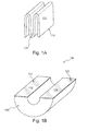
- FIGS. 1A and 1B illustrate examples of a maintenance assembly in deflated and inflated positions, respectively, outside of a gas turbine engine, in accordance with an exemplary embodiment of the present disclosure
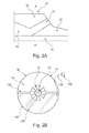
- FIGS. 2A and 2B specifically, FIG. 2A illustrates a side view line representation of a gas turbine engine portion, and FIG. 2B illustrates a cross-sectional view of the gas turbine engine portion along a line A-A' of FIG. 2A , depicting an example maintenance assembly in a working condition within the gas turbine engine portion at a shutdown condition, in accordance with an exemplary embodiment of the present disclosure.
- FIGS. 1A to 2B examples of a maintenance assembly 100 configured to be adaptable within a gas turbine engine 10, are illustrated in accordance with an exemplary embodiment of the present disclosure.
- FIGS. 1A and 1B respectively illustrate an example maintenance assembly in deflated and inflated positions outside of the gas turbine engine 10
- FIGS. 2A and 2B illustrate the maintenance assembly in combination with the gas turbine engine portion at a working condition.
- various associated elements may be well-known to those skilled in the art, it is not deemed necessary for purposes of acquiring an understanding of the present disclosure that there be recited herein all of the constructional details and explanation thereof.
- the maintenance assembly 100 includes a platform 110 and an inflatable member 120.
- the platform 110 and the inflatable member 120 are cooperatively configured to each other.
- the inflatable member 120 is cooperatively configured below of the platform 110.
- the platform 110 may be a one-piece hard structure.
- the platform 110 may be a hard splitable structure. Suitable examples of the one-piece or splitable hard surface structure of the platform 110 from which it may be made include, but not limiting to, woods, laminates etc.
- the inflatable member 120 may be made of a suitable material that is capable of withstanding the pressure and holding medium that may be utilized to inflate thereto.
- the maintenance assembly 100 is capable of being arranged within the gas turbine engine 10 at a shutdown condition for enabling workers to perform maintenance activities therewithin.
- the term maintenance activities includes, but not limiting to, various activities, such as assembly, disassembly or timely and preventive maintenance, that are required to be performed within the gas turbine engine 10 to avoid any unnecessary breakdown or accidents.
- the gas turbine engine 10 as shown in FIGS. 2A and 2B , includes a cavity 12, generally around a combustor 14.
- the combustor 14 is shown around a rotor 18.
- the gas turbine engine 10 is shown to include a typical arrangement depicting a turbine 20 and a compressor 22.
- the cavity 12 is accessible from a manhole 16 of the gas turbine engine 10 for providing the maintenance assembly 100 within the gas turbine engine 10 for enabling the workers to perform maintenance activities within the gas turbine engine.
- the maintenance assembly 100 is provided within the cavity 12 through manhole 14 and required to be inflated.
- An exemplary inflated maintenance assembly 100 outside of the cavity can be seen in FIG. 1B .
- the inflatable member 120 is being inflated to adapt an inflated position. At the inflated position, as shown in FIG.
- the inflatable member 120 accommodates a shape that coordinates the cavity 10 in such a manner that the platform 110 is advance within the cavity 12 up to a predetermined level to enable the workers on the platform 110 to reach at a predetermined position within the cavity 12 to perform the maintenance activities within the gas turbine engine 10.
- the platform 110 is adapted to be advanced up to the predetermined position, which may be at least up to a lower half position of the cavity 12.
- the platform 110 is adapted to be advanced by the inflatable member 120. Where the platform 110 is the hard splitable structure, it is adapted to be expended and advanced to form a flat and split surface 112 around the combustor 14 of the gas turbine engine 10. Further, where the platform 110 is the one-piece structure, it is adapted to be expended and advanced below the combustor 14 level.
- the maintenance assembly 100 includes an inflating source 130 adapted to be configured to the inflatable member 120 to inflate the inflatable member 120.
- the inflating source 130 may be adapted to be disposed outside of the cavity 12.
- the inflating source 130 from the outside of the cavity 12 is fluidically connected, via a pipe 132, to inflate the inflatable member 120 within the cavity 12.
- the inflatable member 120 may incorporate a socket 122 to connect the pipe 132.
- the inflating source 130 may be a pump of suitable power to pneumatically or hydraulically inflate the inflating source 130.
- the inflating source 130 may be deposed within the cavity 12 for inflating the inflatable member 120.
- the maintenance assembly in combination with the gas turbine engine of the present disclosure is advantageous in various scopes.
- the maintenance assembly a compact and preassembled assembly which may be easily adaptable within the gas turbine engines. This precludes or minimizes the risk of accidents, and associated problems and time involved in carrying and assembling, as required in conventional structures, every time workers are required to perform various activities, such as maintenance, assembling or disassembling within the gas turbine engine. Further, adaptability of the maintenance assembly within the gas turbine engine makes the maintenance activities within the gas turbine engine convenient and effective in economical manner.
Landscapes
- Engineering & Computer Science (AREA)
- Architecture (AREA)
- Mechanical Engineering (AREA)
- Structural Engineering (AREA)
- General Engineering & Computer Science (AREA)
- Chemical & Material Sciences (AREA)
- Combustion & Propulsion (AREA)
- Civil Engineering (AREA)
- Life Sciences & Earth Sciences (AREA)
- Geology (AREA)
- Turbine Rotor Nozzle Sealing (AREA)
- Wind Motors (AREA)
Abstract
Description
- The present disclosure relates to maintenance activities of gas turbine engines, and, more particularly, to a maintenance assembly being arranged within a gas turbine engine for performing maintenance activities therewithin.
- More often than not, in gas turbines, during closed conditions, it may be required for a worker to enter within a mid-section of an engine through a manhole for assembly, disassembly or timely and preventive maintenance to avoid any unnecessary breakdown or accidents, and to enable its effective and efficient working. For smaller gas turbines, it may be easy for workers to perform such activities, however, in case of larger gas turbines the workers may found quite difficult to perform such activities due to accessibility issues. In order to avoid such accessibility issues, conventionally, the workers may require carrying a set of unassembled components within the cavity of the engines from the manhole. Subsequently, such set of components are required to be assembled within the cavity of the gas turbine engine to form a suitable structure, such as a platform or scaffold etc., for enabling the workers to perform the maintenance activities within the gas turbine engine.
- However, carrying such unassembled set of components within the engine's mid-section through the manhole, which are generally small in size, is quite a cumbersome task with potential Environment, Health and Safety (EHS) risks. Further, subsequent assembling of such set of components within the cavity to form the structure also adds to cumbersomeness, apart from long time in such assemblage.
- Such conventional techniques may be quite in practice, and may have generally been considered satisfactory for their intended purposes, but may be unsatisfactory in terms of precluding risk of accidents and associated problems and huge time involved in carrying and assembling the structures every time the workers required to perform maintenance activities within the gas turbine engine.
- Accordingly, there exists a need to preclude or minimize various such associated problems in an economical and adaptable manner.
- The present disclosure describes a maintenance assembly adaptable within a gas turbine engine, that will be presented in the following simplified summary to provide a basic understanding of one or more aspects of the disclosure that are intended to overcome the discussed drawbacks, but to include all advantages thereof, along with providing some additional advantages. This summary is not an extensive overview of the disclosure. It is intended to neither identify key or critical elements of the disclosure, nor to delineate the scope of the present disclosure. Rather, the sole purpose of this summary is to present some concepts of the disclosure, its aspects and advantages in a simplified form as a prelude to the more detailed description that is presented hereinafter.
- An object of the present disclosure is to describe a maintenance assembly adaptable within gas turbine engines, which may be capable of precluding or minimizing risk of accidents, and associated problems and time involved in carrying and assembling structures every time workers required to perform various activities, such as maintenance, assembling or disassembling within the gas turbine engine. Another object of the present disclosure is to describe a maintenance assembly adaptable with gas turbine engine, which is convenient to use in an effective and economical way. Various other objects and features of the present disclosure will be apparent from the following detailed description and claims.
- The above noted and other objects, in one aspect, may be achieved by a maintenance assembly adaptable within a gas turbine engine for workers to perform maintenance activities within the gas turbine engine. Specifically, the maintenance assembly is capable of being arranged within a cavity, generally around a combustor, accessible from a manhole of the gas turbine engine. The maintenance assembly includes a platform capable of carrying the workers; and an inflatable member cooperatively configured to the platform. The inflatable member at a normal condition, when placed outside of the cavity of the gas turbine engine, being at a deflated position. The inflatable member at a working condition, when arranged within the cavity of the gas turbine engine, being at inflated position so as to accommodate a shape coordinating the cavity in such a manner that the platform is advance within the cavity up to a predetermined level to enable the workers on the platform to reach at a predetermined position within the cavity to perform the maintenance activities within the gas turbine engine.
- In one embodiment, the
maintenance assembly 100 may include an inflating source adapted to be configured to the inflatable member to inflate the inflatable member. - These together with the other aspects of the present disclosure, along with the various features of novelty that characterize the present disclosure, are pointed out with particularity in the present disclosure. For a better understanding of the present disclosure, its operating advantages, and its uses, reference should be made to the accompanying drawings and descriptive matter in which there are illustrated exemplary embodiments of the present disclosure.
- The advantages and features of the present disclosure will be better understood with reference to the following detailed description and claims taken in conjunction with the accompanying drawing, wherein like elements are identified with like symbols, and in which:
-
FIGS. 1A and 1B illustrate examples of a maintenance assembly in deflated and inflated positions, respectively, outside of a gas turbine engine, in accordance with an exemplary embodiment of the present disclosure; and -
FIGS. 2A and 2B , specifically,FIG. 2A illustrates a side view line representation of a gas turbine engine portion, andFIG. 2B illustrates a cross-sectional view of the gas turbine engine portion along a line A-A' ofFIG. 2A , depicting an example maintenance assembly in a working condition within the gas turbine engine portion at a shutdown condition, in accordance with an exemplary embodiment of the present disclosure. - Like reference numerals refer to like parts throughout the description of several views of the drawings.
- For a thorough understanding of the present disclosure, reference is to be made to the following detailed description, including the appended claims, in connection with the above described drawings. In the following description, for purposes of explanation, numerous specific details are set forth in order to provide a thorough understanding of the present disclosure. It will be apparent, however, to one skilled in the art that the present disclosure can be practiced without these specific details. In other instances, structures and apparatuses are shown in block diagrams form only, in order to avoid obscuring the disclosure. Reference in this specification to "one embodiment," "an embodiment," "another embodiment," "various embodiments," means that a particular feature, structure, or characteristic described in connection with the embodiment is included in at least one embodiment of the present disclosure. The appearance of the phrase "in one embodiment" in various places in the specification are not necessarily all referring to the same embodiment, nor are separate or alternative embodiments mutually exclusive of other embodiments. Moreover, various features are described which may be exhibited by some embodiments and not by others. Similarly, various requirements are described which may be requirements for some embodiments but may not be of other embodiment's requirement.
- Although the following description contains many specifics for the purposes of illustration, anyone skilled in the art will appreciate that many variations and/or alterations to these details are within the scope of the present disclosure. Similarly, although many of the features of the present disclosure are described in terms of each other, or in conjunction with each other, one skilled in the art will appreciate that many of these features can be provided independently of other features. Accordingly, this description of the present disclosure is set forth without any loss of generality to, and without imposing limitations upon, the present disclosure. Further, the relative terms, such as "first," "second," "third" and the like, herein do not denote any order, elevation or importance, but rather are used to distinguish one element from another. Further, the terms "a" and "an" herein do not denote a limitation of quantity, but rather denote the presence of at least one of the referenced item.
- Referring now to
FIGS. 1A to 2B , examples of amaintenance assembly 100 configured to be adaptable within a gas turbine engine 10, are illustrated in accordance with an exemplary embodiment of the present disclosure.FIGS. 1A and 1B , respectively illustrate an example maintenance assembly in deflated and inflated positions outside of the gas turbine engine 10, andFIGS. 2A and 2B , illustrate the maintenance assembly in combination with the gas turbine engine portion at a working condition. In as much as the construction and arrangement of themaintenance assembly 100, and the gas turbine engine 10 in which relation themaintenance assembly 100 are adaptable and used, various associated elements may be well-known to those skilled in the art, it is not deemed necessary for purposes of acquiring an understanding of the present disclosure that there be recited herein all of the constructional details and explanation thereof. Rather, it is deemed sufficient to simply note that as shown inFIGS. 1 to 2B , in themaintenance assembly 100, and the gas turbine engine 10 in which relation themaintenance assembly 100 are adaptable, only those components are shown that are relevant for the description of various embodiments of the present disclosure. - Referring now to
FIGS. 1A, 1B ,2A and 2B , themaintenance assembly 100 includes aplatform 110 and aninflatable member 120. Theplatform 110 and theinflatable member 120 are cooperatively configured to each other. In one example form, theinflatable member 120 is cooperatively configured below of theplatform 110. In one embodiment of the present disclosure, theplatform 110 may be a one-piece hard structure. In another embodiment, theplatform 110 may be a hard splitable structure. Suitable examples of the one-piece or splitable hard surface structure of theplatform 110 from which it may be made include, but not limiting to, woods, laminates etc. Further, theinflatable member 120 may be made of a suitable material that is capable of withstanding the pressure and holding medium that may be utilized to inflate thereto. - The
maintenance assembly 100 is capable of being arranged within the gas turbine engine 10 at a shutdown condition for enabling workers to perform maintenance activities therewithin. The term maintenance activities includes, but not limiting to, various activities, such as assembly, disassembly or timely and preventive maintenance, that are required to be performed within the gas turbine engine 10 to avoid any unnecessary breakdown or accidents. Specifically, the gas turbine engine 10, as shown inFIGS. 2A and 2B , includes acavity 12, generally around acombustor 14. Thecombustor 14 is shown around arotor 18. Further, the gas turbine engine 10 is shown to include a typical arrangement depicting aturbine 20 and acompressor 22. Thecavity 12 is accessible from amanhole 16 of the gas turbine engine 10 for providing themaintenance assembly 100 within the gas turbine engine 10 for enabling the workers to perform maintenance activities within the gas turbine engine. - A
maintenance assembly 100 at a normal condition, as shown inFIG. 1A , when placed outside of thecavity 12 of the gas turbine engine 10, is at a deflated position. When the workers need to perform the maintenance activities within the gas turbine engine 10, themaintenance assembly 100 is provided within thecavity 12 throughmanhole 14 and required to be inflated. An exemplaryinflated maintenance assembly 100 outside of the cavity can be seen inFIG. 1B . Once themaintenance assembly 100 is provided within the cavity, it is required to enable thereto to bring in a working condition. At the working condition, when arranged within thecavity 12 of the gas turbine engine 10, theinflatable member 120 is being inflated to adapt an inflated position. At the inflated position, as shown inFIG. 2B , theinflatable member 120 accommodates a shape that coordinates the cavity 10 in such a manner that theplatform 110 is advance within thecavity 12 up to a predetermined level to enable the workers on theplatform 110 to reach at a predetermined position within thecavity 12 to perform the maintenance activities within the gas turbine engine 10. In an example, theplatform 110 is adapted to be advanced up to the predetermined position, which may be at least up to a lower half position of thecavity 12. - At the working condition, the
platform 110 is adapted to be advanced by theinflatable member 120. Where theplatform 110 is the hard splitable structure, it is adapted to be expended and advanced to form a flat and splitsurface 112 around thecombustor 14 of the gas turbine engine 10. Further, where theplatform 110 is the one-piece structure, it is adapted to be expended and advanced below thecombustor 14 level. - In an embodiment, the
maintenance assembly 100 includes an inflatingsource 130 adapted to be configured to theinflatable member 120 to inflate theinflatable member 120. The inflatingsource 130 may be adapted to be disposed outside of thecavity 12. The inflatingsource 130 from the outside of thecavity 12 is fluidically connected, via apipe 132, to inflate theinflatable member 120 within thecavity 12. Theinflatable member 120 may incorporate asocket 122 to connect thepipe 132. In an example, the inflatingsource 130 may be a pump of suitable power to pneumatically or hydraulically inflate the inflatingsource 130. However, without departing form the scope of the present disclosure, the inflatingsource 130 may be deposed within thecavity 12 for inflating theinflatable member 120. - The maintenance assembly in combination with the gas turbine engine of the present disclosure is advantageous in various scopes. The maintenance assembly a compact and preassembled assembly which may be easily adaptable within the gas turbine engines. This precludes or minimizes the risk of accidents, and associated problems and time involved in carrying and assembling, as required in conventional structures, every time workers are required to perform various activities, such as maintenance, assembling or disassembling within the gas turbine engine. Further, adaptability of the maintenance assembly within the gas turbine engine makes the maintenance activities within the gas turbine engine convenient and effective in economical manner. Various other advantages and features of the present disclosure are apparent from the above detailed description and appendage claims.
- The foregoing descriptions of specific embodiments of the present disclosure have been presented for purposes of illustration and description. They are not intended to be exhaustive or to limit the present disclosure to the precise forms disclosed, and obviously many modifications and variations are possible in light of the above teaching. The embodiments were chosen and described in order to best explain the principles of the present disclosure and its practical application, to thereby enable others skilled in the art to best utilize the present disclosure and various embodiments with various modifications as are suited to the particular use contemplated. It is understood that various omission and substitutions of equivalents are contemplated as circumstance may suggest or render expedient, but such are intended to cover the application or implementation without departing from the spirit or scope of the claims of the present disclosure.
-
- 100
- Maintenance assembly
- 110
- Platform
- 112
- Flat and split surface
- 120
- Inflatable member
- 122
- Socket
- 130
- Inflating source
- 132
- Pipe
- 10
- Gas turbine engine
- 12
- Cavity
- 14
- Combustor
- 16
- Manhole
- 18
- Rotor
- 20
- Turbine
- 22
- Compressor
Claims (9)
- A maintenance assembly 100 for workers to perform maintenance activities within a gas turbine engine 10, the maintenance assembly 100 capable of being arranged within a cavity 12, generally around a combustor 14, accessible from a manhole 16 of the gas turbine engine 10, the maintenance assembly 100 comprising:a platform 110 capable of carrying the workers; andan inflatable member 120 cooperatively configured to the platform 110, the inflatable member 120:at a normal condition, when placed outside of the cavity 12 of the gas turbine engine 10, being at a deflated position;at a working condition, when arranged within the cavity 12 of the gas turbine engine 10, being at inflated position so as to accommodate a shape coordinating the cavity 10 in such a manner that the platform 110 is advance within the cavity 12 up to a predetermined level to enable the workers on the platform 110 to reach at a predetermined position within the cavity 12 to perform the maintenance activities within the gas turbine engine 10.
- The maintenance assembly 100 as claimed in claim 1, wherein the platform 110 is a hard splitable structure adapted to be expended and advanced to form a flat and split surface 112 around the combustor 14 of the gas turbine engine 10 at the working condition.
- The maintenance assembly 100 as claimed in claim 1, wherein the platform 110 is a one-piece hard structure adapted to be advanced at the working condition.
- The maintenance assembly 100 as claimed in claim 1, wherein the platform 110 is adapted to be advanced up to the predetermined position, which is at least up to a lower half position of the cavity 12.
- The maintenance assembly 100 as claimed in claim 1, wherein the inflatable member 120 is cooperatively configured below of the platform 110.
- The maintenance assembly 100 as claimed in claim 1, wherein the inflatable member 120, in the working condition, at the inflated position adapted to be expended around the combustor 14 of the gas turbine engine 10.
- The maintenance assembly 100 as claimed in claim 1 further comprising an inflating source 130 adapted to be configured to the inflatable member 120 to inflate the inflatable member 120.
- The maintenance assembly 100 as claimed in claim 7, wherein the inflating source 130 is adapted to be disposed outside of the cavity 12, the inflating source 130 from the outside of the cavity 12 is fluidically connected to inflate the inflatable member 120 within the cavity 12.
- The maintenance assembly 100 as claimed in claim 7, wherein the inflating source 130 is one of a pneumatic and hydraulic inflating source.
Priority Applications (3)
| Application Number | Priority Date | Filing Date | Title |
|---|---|---|---|
| EP13177623.9A EP2829690A1 (en) | 2013-07-23 | 2013-07-23 | Maintenance assembly adaptable within gas turbine engine |
| US14/335,100 US9540829B2 (en) | 2013-07-23 | 2014-07-18 | Maintenance assembly adaptable within gas turbine engine |
| CN201410351732.5A CN104343540B (en) | 2013-07-23 | 2014-07-23 | Maintenance assembly adaptable within gas turbine engine |
Applications Claiming Priority (1)
| Application Number | Priority Date | Filing Date | Title |
|---|---|---|---|
| EP13177623.9A EP2829690A1 (en) | 2013-07-23 | 2013-07-23 | Maintenance assembly adaptable within gas turbine engine |
Publications (1)
| Publication Number | Publication Date |
|---|---|
| EP2829690A1 true EP2829690A1 (en) | 2015-01-28 |
Family
ID=48856526
Family Applications (1)
| Application Number | Title | Priority Date | Filing Date |
|---|---|---|---|
| EP13177623.9A Withdrawn EP2829690A1 (en) | 2013-07-23 | 2013-07-23 | Maintenance assembly adaptable within gas turbine engine |
Country Status (3)
| Country | Link |
|---|---|
| US (1) | US9540829B2 (en) |
| EP (1) | EP2829690A1 (en) |
| CN (1) | CN104343540B (en) |
Cited By (1)
| Publication number | Priority date | Publication date | Assignee | Title |
|---|---|---|---|---|
| CN113919088A (en) * | 2021-09-15 | 2022-01-11 | 中国船舶重工集团公司第七0三研究所 | Method for designing middle-stage anti-surge deflation position of gas turbine compressor at low rotating speed |
Families Citing this family (3)
| Publication number | Priority date | Publication date | Assignee | Title |
|---|---|---|---|---|
| US20160069094A1 (en) * | 2006-08-05 | 2016-03-10 | Donald F. Lombardi | Mason's adjustable chimney-platform arrangement |
| US10378222B1 (en) * | 2017-03-14 | 2019-08-13 | Hicham Elanmati | Inflatable scaffolding |
| CN113792503B (en) * | 2021-09-15 | 2024-04-02 | 中国船舶重工集团公司第七0三研究所 | Low-working-condition interstage deflation anti-surge method for low-pressure compressor of marine gas turbine |
Citations (3)
| Publication number | Priority date | Publication date | Assignee | Title |
|---|---|---|---|---|
| US3279192A (en) * | 1963-12-30 | 1966-10-18 | Gen Electric | Variable area exhaust nozzle |
| US3323307A (en) * | 1966-01-26 | 1967-06-06 | Lockheed Aircraft Corp | Turbofan jet engine tool |
| US4199301A (en) * | 1976-08-13 | 1980-04-22 | Bbc Brown Boveri & Company Limited | Housing for thermal apparatus and fluid flow machines particularly a steam turbine |
Family Cites Families (64)
| Publication number | Priority date | Publication date | Assignee | Title |
|---|---|---|---|---|
| US2361832A (en) * | 1941-10-31 | 1944-10-31 | Eyles George Frederick | Fluid pressure lifting means |
| US2609177A (en) * | 1948-12-15 | 1952-09-02 | George E Hughes | Automobile jack |
| USRE24272E (en) * | 1952-01-07 | 1957-02-12 | Land vehicle or load-moving device comprising | |
| US3799504A (en) * | 1972-05-02 | 1974-03-26 | J Vaughen | Pneumatically operated lift device |
| US3840922A (en) * | 1972-11-03 | 1974-10-15 | Thermo Flex Inc | Landing cushion for falling objects |
| US3948344A (en) * | 1974-10-03 | 1976-04-06 | Johnson Raynor A | Low cost planar air pallet material handling system |
| DE7533295U (en) * | 1975-10-20 | 1976-02-26 | Vetter, Manfred, 5352 Zuelpich | LIFTING BAGS FOR LIFTING, SUPPORTING AND MOVING LOADS |
| GB1604141A (en) * | 1978-01-05 | 1981-12-02 | Modern Precision Engs & Associ | Air cushion lifting device |
| US4470578A (en) * | 1979-03-30 | 1984-09-11 | Idux Industriell Exploatering Aktiebolag | Load transfer device |
| US4372533A (en) * | 1980-05-19 | 1983-02-08 | Goodyear Aerospace Corporation | Pneumatic lift pad |
| IT1142775B (en) * | 1981-05-22 | 1986-10-15 | Alitalia Spa | HYDRO-PNEUMATIC POSITIONER FOR THE CHANGE OF WING AIRCRAFT ENGINES TO SIMILAR |
| GB2106183B (en) * | 1981-09-19 | 1986-04-03 | Peter Selwyn Kerton | Animal lifting device |
| GB8323675D0 (en) * | 1983-09-03 | 1983-10-05 | Snell T B | Lifting devices |
| US4678157A (en) * | 1984-08-30 | 1987-07-07 | Robert Fondiller | Apparatus for the construction of a low cost structure |
| US4746471A (en) * | 1984-11-14 | 1988-05-24 | Hale Loren E | Method of constructing a reinforced concrete structure |
| US4629162A (en) * | 1985-05-02 | 1986-12-16 | Porche Albert J | Pneumatic invalid lift |
| DE3516676A1 (en) * | 1985-05-09 | 1986-11-20 | Deutsche Schlauchbootfabrik Hans Scheibert GmbH & Co KG, 3456 Eschershausen | JUMP RESCUE DEVICE |
| US4712335A (en) * | 1986-12-17 | 1987-12-15 | Barkdull Jr Howard L | Method of span construction |
| US4865096A (en) * | 1988-08-16 | 1989-09-12 | American Fuel Cell And Coated Fabrics Company | Lightweight pillow tank |
| IT1229892B (en) * | 1989-02-16 | 1991-09-13 | Pirelli | EMERGENCY DEVICE TO ALLOW THE TRANSFER OF A PLURALITY OF PEOPLE BETWEEN TWO AREAS DISTANT BETWEEN THEM |
| JPH086455B2 (en) * | 1989-02-20 | 1996-01-24 | 株式会社フジタ | Working scaffolding inside a tubular structure |
| DE8914694U1 (en) * | 1989-12-14 | 1990-04-19 | Vetter, Manfred, 5352 Zülpich | Lifting bags with two reinforced walls made of rubber or a rubber-like material |
| NO311989B1 (en) * | 1990-11-05 | 2002-02-25 | Audun Haugs | Device by tensioning means |
| IL96825A0 (en) * | 1990-12-30 | 1991-09-16 | Pavie Henry | Inflatable construction apparatus |
| US5131503A (en) * | 1991-01-29 | 1992-07-21 | Billington Welding & Manufacturing, Inc. | Vertically adjustable work station assembly |
| US5119907A (en) * | 1991-01-29 | 1992-06-09 | Billington Welding & Manufacturing, Inc. | Vertically adjustable work station assembly |
| AU663302B2 (en) * | 1991-02-12 | 1995-10-05 | Void Formers Limited | Building method and apparatus |
| ZA935564B (en) * | 1992-08-06 | 1994-03-02 | De Beers Ind Diamond | Formwork apparatus |
| DE4227094C2 (en) * | 1992-08-17 | 2001-02-08 | Man Technologie Gmbh | Pneumatic floor support for layable bridges |
| US5785148A (en) * | 1993-12-27 | 1998-07-28 | Wildner; Robert J. | Environmentally safe work platform with buoyancy system |
| US5522181A (en) * | 1994-05-26 | 1996-06-04 | Ellsworth; Thayne N. | Devices for the rapid deployment of igloos |
| DE9418076U1 (en) * | 1994-11-11 | 1995-01-12 | Festo Kg, 73734 Esslingen | Structural engineering structure |
| US5542806A (en) * | 1995-03-31 | 1996-08-06 | The Champion Company | Fluid actuated lifting and tilting device |
| US5668421A (en) * | 1995-04-06 | 1997-09-16 | E. B. Eddy Forest Products Ltd. | Pressurized air-gap guided active linear motor suspension system |
| US6082743A (en) * | 1995-12-11 | 2000-07-04 | Tp-Jac, Inc. | Method of leveling a recreational vehicle |
| GB9613077D0 (en) * | 1996-06-21 | 1996-08-28 | Mangar International Ltd | Pneumatically inflatable lifting devices and valve assemblies for lifting such devices |
| US5931248A (en) * | 1997-09-15 | 1999-08-03 | The United States Of America As Represented By The Secretary Of The Navy | Durable roll-stabilizing keel system for hovercraft |
| US6176113B1 (en) * | 1999-02-19 | 2001-01-23 | White, Iii Harold J. | Inflatable device for removing dents in components of vehicles |
| US6520449B2 (en) * | 1999-05-21 | 2003-02-18 | Vortex Holding Company | Lifting platform with positive horizontal stability |
| US6543730B2 (en) * | 2000-03-27 | 2003-04-08 | Mauro Pedretti | Pneumatic structural element |
| US6648507B2 (en) * | 2000-04-19 | 2003-11-18 | Gta Containers, Inc. | Collapsible storage tank for liquids |
| US6551091B1 (en) * | 2000-09-14 | 2003-04-22 | The Boeing Company | Flexible inflatable support structure for use with a reusable compaction bag |
| ATE284999T1 (en) * | 2001-07-20 | 2005-01-15 | Prospective Concepts Ag | PNEUMATIC STRUCTURAL OR BRIDGE ELEMENT |
| US20040217338A1 (en) * | 2003-04-30 | 2004-11-04 | Abrahamson Guy A. | Device and method for leveling recreational vehicles |
| US6948590B1 (en) * | 2003-08-21 | 2005-09-27 | Bellsouth Intellectual Property Corporation | Redundant systems utilizing inflatable devices in association with utility structures |
| US20060027276A1 (en) * | 2003-10-20 | 2006-02-09 | Alford Main | Seamless inflatable bag with multiple applications |
| WO2005058222A2 (en) * | 2003-12-17 | 2005-06-30 | Davis David T | Pneumatic lift |
| ITTO20040150A1 (en) * | 2004-03-10 | 2004-06-10 | Torino Politecnico | DOUBLE ACTING THREE CHAMBER FLUID ACTUATOR |
| EP1802551B1 (en) * | 2004-09-04 | 2010-10-27 | Middlegate Marketing Limited | Load handling apparatus, an inflatable bag therefor, vehicles and trailers incorporating moveable laod carrying platforms |
| US7328622B2 (en) * | 2005-06-30 | 2008-02-12 | The Boeing Company | Soft support systems and methods for dynamically testing structures |
| US7779540B2 (en) | 2005-08-12 | 2010-08-24 | United Technologies Corporation | Apparatus and method for quadrail ergonomic assembly |
| DE102005047486B4 (en) * | 2005-10-04 | 2007-06-14 | Eisenmann Anlagenbau Gmbh & Co. Kg | Lift table |
| US7926787B2 (en) * | 2006-11-21 | 2011-04-19 | Blue Sky Decks, Llc | Elevated platform and method of elevating the same |
| US8702059B2 (en) * | 2006-11-21 | 2014-04-22 | Craig Wieland | Elevated platform and method of elevating the same |
| US7845577B2 (en) * | 2007-08-05 | 2010-12-07 | Pillwtrack Ltd. | Inflatable automative traction recovery device |
| US8413960B2 (en) * | 2009-06-25 | 2013-04-09 | Brent E. Davis | Inflatable equipment stabilizer |
| US8548626B2 (en) * | 2009-09-03 | 2013-10-01 | Irobot Corporation | Method and device for manipulating an object |
| SI2332879T1 (en) * | 2009-12-09 | 2013-05-31 | Vetter Gmbh | Lifting bag of web-like rubber material hot-vulcanized in a press and method for its production |
| US9056755B1 (en) * | 2010-10-07 | 2015-06-16 | Daniel W. Moy | Compact air compressor and vehicle jack |
| US8322492B1 (en) * | 2011-01-05 | 2012-12-04 | Balzano John F | Ladder system with integrated air bags at base |
| US9228451B2 (en) | 2011-05-03 | 2016-01-05 | Pratt & Whitney Canada Corp. | Gas turbine engine module adapter to a carrier |
| GB2495988A (en) * | 2011-10-28 | 2013-05-01 | Perry Williamson | Expanding support for an excavation |
| US9279260B2 (en) * | 2012-10-12 | 2016-03-08 | Norton Baum | Modular panel concrete form for self-lifting concrete form system |
| US9303794B2 (en) * | 2013-11-11 | 2016-04-05 | James Pirtle | Buried pipeline repair system |
-
2013
- 2013-07-23 EP EP13177623.9A patent/EP2829690A1/en not_active Withdrawn
-
2014
- 2014-07-18 US US14/335,100 patent/US9540829B2/en not_active Expired - Fee Related
- 2014-07-23 CN CN201410351732.5A patent/CN104343540B/en not_active Expired - Fee Related
Patent Citations (3)
| Publication number | Priority date | Publication date | Assignee | Title |
|---|---|---|---|---|
| US3279192A (en) * | 1963-12-30 | 1966-10-18 | Gen Electric | Variable area exhaust nozzle |
| US3323307A (en) * | 1966-01-26 | 1967-06-06 | Lockheed Aircraft Corp | Turbofan jet engine tool |
| US4199301A (en) * | 1976-08-13 | 1980-04-22 | Bbc Brown Boveri & Company Limited | Housing for thermal apparatus and fluid flow machines particularly a steam turbine |
Cited By (2)
| Publication number | Priority date | Publication date | Assignee | Title |
|---|---|---|---|---|
| CN113919088A (en) * | 2021-09-15 | 2022-01-11 | 中国船舶重工集团公司第七0三研究所 | Method for designing middle-stage anti-surge deflation position of gas turbine compressor at low rotating speed |
| CN113919088B (en) * | 2021-09-15 | 2024-11-29 | 中国船舶重工集团公司第七0三研究所 | Method for designing middle stage anti-asthma deflation position of gas turbine compressor at low rotation speed |
Also Published As
| Publication number | Publication date |
|---|---|
| CN104343540A (en) | 2015-02-11 |
| CN104343540B (en) | 2017-04-12 |
| US20150027811A1 (en) | 2015-01-29 |
| US9540829B2 (en) | 2017-01-10 |
Similar Documents
| Publication | Publication Date | Title |
|---|---|---|
| EP2829690A1 (en) | Maintenance assembly adaptable within gas turbine engine | |
| GB2568143B (en) | Outlet guide vane for turbomachine, comprising a lubricant cooling passage equipped with a thermal conducting matrix compressed between the intrados and | |
| EP2584152A3 (en) | Mid turbine frame (MTF) for a gas turbine engine | |
| EP4411128A3 (en) | Propulsion system arrangement for turbofan gas turbine engine | |
| EP3225779B1 (en) | Removal tool | |
| WO2014130103A3 (en) | Integrated heat exchangers for low fan pressure ratio geared turbofan | |
| EP2584168A3 (en) | Integrated thermal system for a gas turbine engine | |
| EP2613014A3 (en) | Stage of a gas turbine engine and corresponding method of retrofitting | |
| WO2011117560A3 (en) | Turbojet venting pipe, method for mounting one such pipe and turbojet provided with one such pipe | |
| EP2388435A3 (en) | Turbine blade with cooled platform | |
| BRPI1006159A2 (en) | "process and system for monitoring vibratory phenomena that occur in a working aircraft gas turbine engine." | |
| EP2354451A3 (en) | Turbine seal plate assembly | |
| US9677428B2 (en) | Removal device | |
| EP2511482A3 (en) | Turbine shroud segment cooling system and method | |
| EP2108786A3 (en) | Aeroengine fan assembly | |
| EP2657451A3 (en) | Turbine shroud cooling assembly for a gas turbine system | |
| EP2395202A3 (en) | A mounting assembly for a gearbox of gas turbine engine | |
| EP2826708A3 (en) | Wind turbine rotor blade assembly with surface features | |
| EP2615244A3 (en) | Film cooled turbine airfoil having a plurality of trench segments on the exterior surface | |
| EP2644836A3 (en) | Effusion cooled shroud segment with an abradable coating | |
| EP2554795A3 (en) | Vane assembly for a gas turbine engine | |
| EP2479383A3 (en) | Gas Turbine Engine Stator Vane Assembly | |
| EP2615245A3 (en) | Film cooled turbine airfoil having trench segments on the exterior surface | |
| WO2014189589A3 (en) | Gas turbine engine with soft mounted pre-swirl nozzle | |
| EP2527592A3 (en) | Tool for removing pins from a gas turbine casing |
Legal Events
| Date | Code | Title | Description |
|---|---|---|---|
| 17P | Request for examination filed |
Effective date: 20130723 |
|
| AK | Designated contracting states |
Kind code of ref document: A1 Designated state(s): AL AT BE BG CH CY CZ DE DK EE ES FI FR GB GR HR HU IE IS IT LI LT LU LV MC MK MT NL NO PL PT RO RS SE SI SK SM TR |
|
| AX | Request for extension of the european patent |
Extension state: BA ME |
|
| PUAI | Public reference made under article 153(3) epc to a published international application that has entered the european phase |
Free format text: ORIGINAL CODE: 0009012 |
|
| R17P | Request for examination filed (corrected) |
Effective date: 20150723 |
|
| RBV | Designated contracting states (corrected) |
Designated state(s): AL AT BE BG CH CY CZ DE DK EE ES FI FR GB GR HR HU IE IS IT LI LT LU LV MC MK MT NL NO PL PT RO RS SE SI SK SM TR |
|
| RAP1 | Party data changed (applicant data changed or rights of an application transferred) |
Owner name: GENERAL ELECTRIC TECHNOLOGY GMBH |
|
| RAP1 | Party data changed (applicant data changed or rights of an application transferred) |
Owner name: ANSALDO ENERGIA SWITZERLAND AG |
|
| STAA | Information on the status of an ep patent application or granted ep patent |
Free format text: STATUS: THE APPLICATION IS DEEMED TO BE WITHDRAWN |
|
| 18D | Application deemed to be withdrawn |
Effective date: 20190201 |