EP2829688B1 - Method and device for monitoring an APU turbine - Google Patents
Method and device for monitoring an APU turbine Download PDFInfo
- Publication number
- EP2829688B1 EP2829688B1 EP14178425.6A EP14178425A EP2829688B1 EP 2829688 B1 EP2829688 B1 EP 2829688B1 EP 14178425 A EP14178425 A EP 14178425A EP 2829688 B1 EP2829688 B1 EP 2829688B1
- Authority
- EP
- European Patent Office
- Prior art keywords
- apu
- phase
- malfunction
- threshold value
- avg
- Prior art date
- Legal status (The legal status is an assumption and is not a legal conclusion. Google has not performed a legal analysis and makes no representation as to the accuracy of the status listed.)
- Active
Links
- 238000000034 method Methods 0.000 title claims description 69
- 238000012544 monitoring process Methods 0.000 title claims description 41
- 230000007257 malfunction Effects 0.000 claims description 78
- 230000007423 decrease Effects 0.000 claims description 71
- 230000004044 response Effects 0.000 claims description 31
- 230000002829 reductive effect Effects 0.000 claims description 10
- 239000007789 gas Substances 0.000 description 25
- 238000010586 diagram Methods 0.000 description 18
- 230000008859 change Effects 0.000 description 15
- 238000012423 maintenance Methods 0.000 description 10
- 230000008439 repair process Effects 0.000 description 6
- DEFVIWRASFVYLL-UHFFFAOYSA-N ethylene glycol bis(2-aminoethyl)tetraacetic acid Chemical compound OC(=O)CN(CC(O)=O)CCOCCOCCN(CC(O)=O)CC(O)=O DEFVIWRASFVYLL-UHFFFAOYSA-N 0.000 description 5
- 230000008569 process Effects 0.000 description 5
- 238000007790 scraping Methods 0.000 description 5
- 238000011217 control strategy Methods 0.000 description 4
- 239000000243 solution Substances 0.000 description 4
- 238000005299 abrasion Methods 0.000 description 3
- 229910003460 diamond Inorganic materials 0.000 description 3
- 239000010432 diamond Substances 0.000 description 3
- 230000000694 effects Effects 0.000 description 3
- 239000000446 fuel Substances 0.000 description 3
- 239000003550 marker Substances 0.000 description 3
- 239000000463 material Substances 0.000 description 3
- 208000027418 Wounds and injury Diseases 0.000 description 2
- 238000004378 air conditioning Methods 0.000 description 2
- 238000004458 analytical method Methods 0.000 description 2
- 230000008901 benefit Effects 0.000 description 2
- 238000004364 calculation method Methods 0.000 description 2
- 238000004891 communication Methods 0.000 description 2
- 230000006378 damage Effects 0.000 description 2
- 238000001514 detection method Methods 0.000 description 2
- 230000003628 erosive effect Effects 0.000 description 2
- 239000000295 fuel oil Substances 0.000 description 2
- 230000006870 function Effects 0.000 description 2
- 208000014674 injury Diseases 0.000 description 2
- 238000007689 inspection Methods 0.000 description 2
- 230000007774 longterm Effects 0.000 description 2
- 239000002184 metal Substances 0.000 description 2
- 239000007858 starting material Substances 0.000 description 2
- 230000008646 thermal stress Effects 0.000 description 2
- RWSOTUBLDIXVET-UHFFFAOYSA-N Dihydrogen sulfide Chemical compound S RWSOTUBLDIXVET-UHFFFAOYSA-N 0.000 description 1
- 206010061245 Internal injury Diseases 0.000 description 1
- 230000002159 abnormal effect Effects 0.000 description 1
- 239000000654 additive Substances 0.000 description 1
- 230000000996 additive effect Effects 0.000 description 1
- 230000002411 adverse Effects 0.000 description 1
- 230000009286 beneficial effect Effects 0.000 description 1
- 230000003247 decreasing effect Effects 0.000 description 1
- 230000007850 degeneration Effects 0.000 description 1
- 230000001771 impaired effect Effects 0.000 description 1
- 238000002347 injection Methods 0.000 description 1
- 239000007924 injection Substances 0.000 description 1
- 230000002427 irreversible effect Effects 0.000 description 1
- 230000000670 limiting effect Effects 0.000 description 1
- 239000000314 lubricant Substances 0.000 description 1
- 238000005259 measurement Methods 0.000 description 1
- 229940101532 meted Drugs 0.000 description 1
- 238000012986 modification Methods 0.000 description 1
- 230000004048 modification Effects 0.000 description 1
- 230000001105 regulatory effect Effects 0.000 description 1
- 230000000717 retained effect Effects 0.000 description 1
- 238000005201 scrubbing Methods 0.000 description 1
- 208000024891 symptom Diseases 0.000 description 1
- 238000012546 transfer Methods 0.000 description 1
- 239000002918 waste heat Substances 0.000 description 1
- 239000002699 waste material Substances 0.000 description 1
Images


Classifications
-
- G—PHYSICS
- G01—MEASURING; TESTING
- G01M—TESTING STATIC OR DYNAMIC BALANCE OF MACHINES OR STRUCTURES; TESTING OF STRUCTURES OR APPARATUS, NOT OTHERWISE PROVIDED FOR
- G01M15/00—Testing of engines
- G01M15/14—Testing gas-turbine engines or jet-propulsion engines
-
- B—PERFORMING OPERATIONS; TRANSPORTING
- B64—AIRCRAFT; AVIATION; COSMONAUTICS
- B64F—GROUND OR AIRCRAFT-CARRIER-DECK INSTALLATIONS SPECIALLY ADAPTED FOR USE IN CONNECTION WITH AIRCRAFT; DESIGNING, MANUFACTURING, ASSEMBLING, CLEANING, MAINTAINING OR REPAIRING AIRCRAFT, NOT OTHERWISE PROVIDED FOR; HANDLING, TRANSPORTING, TESTING OR INSPECTING AIRCRAFT COMPONENTS, NOT OTHERWISE PROVIDED FOR
- B64F5/00—Designing, manufacturing, assembling, cleaning, maintaining or repairing aircraft, not otherwise provided for; Handling, transporting, testing or inspecting aircraft components, not otherwise provided for
- B64F5/60—Testing or inspecting aircraft components or systems
-
- F—MECHANICAL ENGINEERING; LIGHTING; HEATING; WEAPONS; BLASTING
- F01—MACHINES OR ENGINES IN GENERAL; ENGINE PLANTS IN GENERAL; STEAM ENGINES
- F01D—NON-POSITIVE DISPLACEMENT MACHINES OR ENGINES, e.g. STEAM TURBINES
- F01D21/00—Shutting-down of machines or engines, e.g. in emergency; Regulating, controlling, or safety means not otherwise provided for
- F01D21/04—Shutting-down of machines or engines, e.g. in emergency; Regulating, controlling, or safety means not otherwise provided for responsive to undesired position of rotor relative to stator or to breaking-off of a part of the rotor, e.g. indicating such position
-
- F—MECHANICAL ENGINEERING; LIGHTING; HEATING; WEAPONS; BLASTING
- F02—COMBUSTION ENGINES; HOT-GAS OR COMBUSTION-PRODUCT ENGINE PLANTS
- F02C—GAS-TURBINE PLANTS; AIR INTAKES FOR JET-PROPULSION PLANTS; CONTROLLING FUEL SUPPLY IN AIR-BREATHING JET-PROPULSION PLANTS
- F02C7/00—Features, components parts, details or accessories, not provided for in, or of interest apart form groups F02C1/00 - F02C6/00; Air intakes for jet-propulsion plants
- F02C7/26—Starting; Ignition
-
- G—PHYSICS
- G01—MEASURING; TESTING
- G01N—INVESTIGATING OR ANALYSING MATERIALS BY DETERMINING THEIR CHEMICAL OR PHYSICAL PROPERTIES
- G01N25/00—Investigating or analyzing materials by the use of thermal means
-
- G—PHYSICS
- G05—CONTROLLING; REGULATING
- G05B—CONTROL OR REGULATING SYSTEMS IN GENERAL; FUNCTIONAL ELEMENTS OF SUCH SYSTEMS; MONITORING OR TESTING ARRANGEMENTS FOR SUCH SYSTEMS OR ELEMENTS
- G05B23/00—Testing or monitoring of control systems or parts thereof
- G05B23/02—Electric testing or monitoring
- G05B23/0205—Electric testing or monitoring by means of a monitoring system capable of detecting and responding to faults
- G05B23/0218—Electric testing or monitoring by means of a monitoring system capable of detecting and responding to faults characterised by the fault detection method dealing with either existing or incipient faults
- G05B23/0224—Process history based detection method, e.g. whereby history implies the availability of large amounts of data
- G05B23/0227—Qualitative history assessment, whereby the type of data acted upon, e.g. waveforms, images or patterns, is not relevant, e.g. rule based assessment; if-then decisions
- G05B23/0235—Qualitative history assessment, whereby the type of data acted upon, e.g. waveforms, images or patterns, is not relevant, e.g. rule based assessment; if-then decisions based on a comparison with predetermined threshold or range, e.g. "classical methods", carried out during normal operation; threshold adaptation or choice; when or how to compare with the threshold
-
- F—MECHANICAL ENGINEERING; LIGHTING; HEATING; WEAPONS; BLASTING
- F05—INDEXING SCHEMES RELATING TO ENGINES OR PUMPS IN VARIOUS SUBCLASSES OF CLASSES F01-F04
- F05D—INDEXING SCHEME FOR ASPECTS RELATING TO NON-POSITIVE-DISPLACEMENT MACHINES OR ENGINES, GAS-TURBINES OR JET-PROPULSION PLANTS
- F05D2220/00—Application
- F05D2220/50—Application for auxiliary power units (APU's)
-
- F—MECHANICAL ENGINEERING; LIGHTING; HEATING; WEAPONS; BLASTING
- F05—INDEXING SCHEMES RELATING TO ENGINES OR PUMPS IN VARIOUS SUBCLASSES OF CLASSES F01-F04
- F05D—INDEXING SCHEME FOR ASPECTS RELATING TO NON-POSITIVE-DISPLACEMENT MACHINES OR ENGINES, GAS-TURBINES OR JET-PROPULSION PLANTS
- F05D2270/00—Control
- F05D2270/40—Type of control system
- F05D2270/44—Type of control system active, predictive, or anticipative
Definitions
- the present invention relates to monitoring the malfunction of the aircraft component, in particular to method and device for monitoring the malfunction of turbine vane fracture and rotor shaft jam of aircraft auxiliary power unit.
- Airborne Auxiliary Power Unit is a small turbine engine mounted on the tail of an aircraft. Its main function is to supply power and provide gas sources. Some APUs are capable of providing additive thrust to the aircraft. Specifically, before taking off from the ground, an aircraft may rely on a power and gas supply from the APU, rather than the ground power and gas source vehicles. While on the ground, the APU also supplies power and compressed air to ensure lighting and air-conditioning in the cabin and cockpit. During take-off of an aircraft, the APU can serve as a backup power source. After the aircraft is landed, lighting and air-conditioning of the aircraft are still maintained by power from the APU. The functions of APU influence the flight stability of the aircraft, which directly affects flight cost and quality of service of the aircraft.
- the malfunction of APU turbine vane fracture and rotor shaft jam is a common malfunction of APU.
- the only solution is to replace the engine of APU, and therefore the maintenance cost is very expensive and usually twice with respect to the cost of normal repair. If the malfunction can be found in advance, the maintenance cost will be greatly reduced and the maintenance cycle will be shortened.
- the invention provides the monitoring method for the malfunction of turbine vane fracture and rotor shaft jam to meet the demands in the art.
- EP 2544064 there is disclosed a method for detecting whether performance of an aircraft component is in a steady, decline phase or malfunction by analysis of variations in decline indexes for the component.
- US 2006/195248 there is disclosed a system and method that detect symptoms of faults in the fuel system of a turbine engine.
- a method for monitoring the malfunction of turbine vane fracture and rotor shaft jam comprising: acquiring APU messages at multiple time points within a period; obtaining operation parameters of the APU according to the APU messages, the operation parameters including at least the start time STA for the APU to startup; calculating an average value AVG and the deviation index ⁇ of the start time STA wherein the average value AVG is calculated from the operation parameters obtained within the period; and whether the APU is in stable phase, a decline phase or a malfunction phase characterized in thatin response to the deviation index ⁇ being less than a threshold value of the decline phase, determining that the APU is in stable phase; in response to the deviation index ⁇ being greater than the threshold value of the decline phase and less than a threshold value of the malfunction phase, determining that the APU is in the decline phase; and in response to the deviation index ⁇ is greater than the threshold value of the malfunction phase, determining that the APU is in the malfunction phase, determining that the APU is in the malfunction
- the method described above further comprises: determining the deviation index ⁇ when the circumstances of APU turbine vane fracture and rotor shaft jam is in stable phase; wherein the threshold value of decline is around 2 times than the deviation index, and the threshold value of malfunction is around 6 times than the stable deviation index.
- the decline phase further comprises serious decline phase
- the threshold value of serious decline phase is between the threshold values of decline and malfunction
- response to the deviation index ⁇ is greater than the threshold value of the serious decline and less than the threshold value of malfunction
- the threshold value of the serious decline is around 4 times than the stable deviation index ⁇ .
- the method described above further comprises: obtaining the start time STA on the next time point by updating the APU message at the next time point; response to STAnext is greater than AVG+n ⁇ or less than AVG-n ⁇ , determining whether the STA next+1 obtained according to the further next message related to APU is greater than AVG+n ⁇ or less than AVG- n ⁇ ; and response to the start time STA obtained according to the message related to APU is greater than AVG+n ⁇ or less than AVG- n ⁇ continuously and exceeding the predetermined number Z, issuing the warning.
- response to the start time STA obtained according to the message related to APU is greater than AVG+n ⁇ or less than average value AVG- n ⁇ , recalculating the average value AVG and deviation index ⁇ of the start time STA.
- response to the start time STA obtained according to the message related to APU is greater than AVG+n ⁇ or less than AVG- n ⁇ continuously and exceeding the predetermined number Z, recalculating the average value AVG and deviation index ⁇ of the start time STA.
- response to the start time STA obtained according to the message related to APU is greater than AVG+n ⁇ or less than AVG- n ⁇ continuously and exceeding the predetermined number Z, issuing the warning.
- the method described above further comprises: response to whether the highest exhaust gas temperature on start EGTP reaches the temperature at red line, issuing the warning of the malfunction of APU turbine vane fracture and rotor shaft jam.
- the method described above further comprises that: response to whether the Number of Proportion in APU (NPA) is reduced to the predetermined threshold value when EGT is at its peak on start, issuing the warning of the malfunction of APU turbine vane fracture and rotor shaft jam, wherein the predetermined threshold value is 35-40%; wherein NPA is a percent of a rotation speed of a turbine when an exhaust temperature EGT of APU reaches its peak value in a start stage of APU with respect to a constant rotation speed in normal operation of APU.
- NPA Number of Proportion in APU
- the method further comprises: response to that exhaust gas temperature EGT is close to the red line value or whether the angle of the inlet guide vane IGV appears an upward jump, issuing the warning of the malfunction of APU turbine vane fracture and rotor shaft jam.
- the method further comprises: acquiring the history data of start time STA; and determining whether the start time STA exhibits gradual increase, gradual regular, and then discrete.
- a device for monitoring the circumstances of APU turbine vane fracture and rotor shaft jam comprises: message acquiring unit, which acquires the APU messages within a time period; message analyzing unit, which analyses the required APU operation data, the operation data at least comprises start time STA; and malfunction monitoring unit, which determines the circumstances of APU turbine vane fracture and rotor shaft jam is in stable phase, decline phase or malfunction phase according to the APU operation data.
- a device for monitoring a malfunction of an airborne auxiliary power unit APU turbine vane fracture and rotor shaft jam comprises: a processor; and a memory coupled to the processor, which stores computer-readable codes; the computer-readable codes run in the processor to execute the following steps: acquiring APU messages at multiple time points within a time period; obtaining operation parameters of the APU according to the APU message, the operation parameters at least comprises a start time STA for the APU to startup; calculating the average value AVG and deviation index ⁇ of the start time STA wherein the average value AVG is calculated from the operation parameters obtained within the time period; and determining that the circumstances of APU turbine vane fracture and rotor shaft jam is in a stable phase, a decline phase, or a malfunction phase characterized in that: in response to the deviation index ⁇ being less than a threshold value of the decline phase, determining that the APU is in the stable phase; in response to the deviation index ⁇ being greater than the threshold value of the decline phase and
- Fig.1 is a schematic drawing illustrating the structure of the aircraft APU according to one example of the present invention.
- the aircraft APU mainly comprises power part 100, load part 200 and accessory part 300.
- the power part 100 mainly comprises power compressor 110, turbine component 120 and exhaust component 130.
- the load part 200 mainly comprises load compressor 210.
- the accessory part 300 mainly comprises, among others, accessory gear box 310, starter 320 and generator 330.
- the air stream entering from the inlet is divided into two streams.
- One enters into the power compressor 110 and turbine component 120, and is mainly used for driving the rotation of APU, and then the stream is exhausted through the exhaust component 130; the other stream enters into the load compressor 210, and this stream is pressurized by the load compressor, and mainly used for producing the compressed air for the engine of aircraft.
- a flow control valve is positioned in the inlet of the stream, the valve is inlet guide vane IGV. IGV regulates the opening of the guide vane in real-time according to the actual need of air in the aircraft, and thereby control the air amount entering into the load compressor.
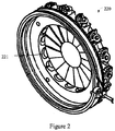
- Fig.2 is a schematic drawing illustrating structure of the inlet guide vane component 220 according to one example of the present invention.
- the inlet guide vane component is substantially disc-shaped.
- a plurality of inlet guide vane IGV221 is positioned on the side close to the bottom of the disc.
- a plurality of inlet guide vane IGV can open with different angles under control, and thus regulate the flow of air entering the load compressor.
- Fig.3 is a curve diagram illustrating the change of the performance of APU caused by the turbine vane fracture and rotor shaft jam according to one example of the present invention. It can be seen from Fig. 3 that: in the early and middle phases in use of APU, the turbine vane of APU is not deformed to stretch or crack, the performance of APU is stable and in stable phase. As the time goes by, because the performance of aircraft APU is gradually degenerated, the decline index is increase. In the late phase in use of APU, the turbine vane of APU becomes deformed to stretch and crack. This phenomenon demonstrates the performance of APU enters into the decline phase. When exceeding some threshold values, the performance of APU enters into the malfunction phase, and APU will encounter a malfunction at any time.
- the detection of decline phase has the following benefits: first, when APU is in decline phase, the probability of the occurrence of a failure is still very low. If the maintenance/repair is proceeded on the aircraft at this time, the flying safety and quality of service can be guaranteed; second, when detecting that the APU is in decline phase, the airline can arrange the maintenance/repair of the aircraft timely, and thus the non-planned maintenance can be avoided, the flight delay can be reduced accordingly, and therefore a waste of the cost for maintenance/repair resulted from the inspection in fixed period can be avoided at the same time.
- the example of the invention can also be applied for the inspection in malfunction phase.
- the malfunction of the APU turbine vane fracture and rotor shaft jam is determined by 3 operation parameters: start time STA, the highest exhaust gas temperature EGTP on start of APU and the NPA (Number of Proportion in APU) at the highest temperature, singly or in combination, wherein the definition of NPA is the percent of the rotation speed of the turbine when the exhaust temperature EGT of APU reaches its peak value in the start stage of APU with respect to the constant rotation speed in normal operation of APU (%RPM/APU RPM). NPA can reflect the vane efficiency of the turbine.
- APU is a small turbine engine
- the clearance dimension between the rotating components and the case largely influences the performance and efficiency of APU; wherein the clearance between the turbine and turbine casing is very important. If the clearance between the turbine and turbine casing is too large, too much gas is lost, and the APU efficiency becomes low. While the clearance between the turbine and turbine casing is too small, the scraping malfunction will easily occur. In general, the clearance between the turbine and turbine casing is very small.
- the inventor of the application finds that, since the turbine vane affected by long-term thermal stress and centrifugal force, the erosion of turbine vane material and release of the turbine vane are apt to occur.
- the change of vane cause the rotator of the turbine to rotate unbalancedly, i.e., eccentric rotation, and as a result the turbine shaft will bend. Such bend is irreversible.
- the bend of the turbine shaft will lead to the scrub between the turbine vane and turbine casing, and finally the vane cracks. Once this case occurs, the situation will get worse with the time.
- the release of vane material will become fast, and the crack of vane will extend, the abrasion will spread.
- the degeneration process of the bend of the APU turbine shaft is relatively long.
- the inventor notes that, at 50°C under zero to 600°C of external temperature, the different expansion coefficients of the turbine vane and turbine casing will cause the clearance between the turbine vane and turbine casing to change with the changes of the external temperature.
- the clearance between the turbine vane and turbine casing will get smaller, and when the external temperature gets lower, the clearance between the turbine vane and turbine casing will get larger.
- the start time STA will return into the range of normal value with a time period.
- the start time STA will reach a top point and become discrete. Since the start time STA is very stable generally, the regular pattern of the change of the start time STA on a long period, that is, top point appearance-returning to normal-top point appearance once again and discrete, is a feature of the malfunction of the APU turbine vane fracture and rotor shaft jam.
- the efficiency of the burning of fuel will decrease accordingly. Since the rotation speed of APU is constant on operation, the burning efficiency must be increased in order to input the same torque, that is, the power loss caused by the low efficiency will be made up by increasing the supply of fuel oil. However, the reduce of efficiency will lead to the increase of waste heat, that is, the circumstance that the consumption of fuel oil increases while the input power remains unchanged will happen. The excess heat will go into the atmosphere with the exhausted gas, causing the increase of the temperature of the exhausted gas. Therefore, the highest exhaust gas temperature EGTP on start of APU will increase gradually with the decrease of pneumatic efficiency of the turbine vane, till it reaches the protected temperature of the exhausted gas (i.e. redline value, about 850°C).
- NPA the efficiency of turbine will be reduced by the bend of turbine shaft, the erosion and release of the vane and the injury caused by scrubbing. NPA will decrease gradually with the decline of the pneumatic efficiency of the turbine vane.
- the standard deviation of the temperature of the exhausted gas EGT, NPA and STA can used as the effective parameters for judging the APU turbine vane fracture and rotor shaft jam sometimes.
- the standard deviation of EGT and NPA increase 30-50%.
- the EGT redline value reflects the limiting value in APU operation.
- the redline value of EGT is 640, and after 50 degrees revise of sea level, the redline of EGT is 690, the standard deviation of STA is 4 and NAP is 40.
- the redline value of EGT is 645, and after 50 degrees revise of sea level, the redline of EGT is 680, the standard deviation of STA is 10 and NAP is 32.
- the temperature of the exhausted gas reaches the redline value, it is not allowed to further increase according the control strategy of APU.
- the torque output must be reduced, that is, reducing the load.
- the air flow entering into the load compressor is regulated by different opening angle of the inlet guide vane IGV. Therefore, APU will increase the angle of the inlet guide vane IGV, and reduce the air flow entering into the load compressor, and thus reduce the bleed air supply to the main engine. Therefore, the angle of the inlet guide vane IGV will change correspondingly.
- the angle of IGV can represent the performance of APU. GTCP131-9A, the IGV redline is 85 degrees, and the IGV redline of APS3200 is 15 degrees.
- the start time STA, the highest exhaust gas temperature on start EGTP, NPA, the revised value of the exhausted temperature EGT and IGV are selected to realize the monitoring for the malfunction of the APU turbine vane fracture and rotor shaft jam.
- the APU operation parameters such as the start time STA, the highest exhaust gas temperature on start EGTP, NPA, the revised value of the exhausted temperature EGT and IGV can be acquired by various methods.
- the above data can be acquired from the data stored in black box of the airplane and digital flight data interface unit DFDIU.
- the above data can also be acquired by the data system supplied by the airplane makers and the real-time monitoring of the ground can also be realized.
- the Aircraft Condition Monitoring System (ACMS) of Airbus and the Aircraft Heath Monitor (AHM) system of Boeing can both realize the monitoring of the operation data of the aircrafts.
- the message comprising a series of data information will be generated automatically.
- the related operation data of APU can be acquired by the aircraft data system (such as ACMS or AHM systems) and embodied in the generated relevant messages. Moreover, this kind of message information can be transferred to the ground by Aircraft Communications Addressing and Reporting System (ACARS), and further distributed to the servers of different airlines. According to one embodiment of the invention, APU message can also be transferred by the communicating device or system of Aviation Telecommunication Network (ATN). Of course, the mode of message transfer can avoid the high cost and human failure caused by manual mode.
- ATN Aviation Telecommunication Network
- the monitoring for the malfunction of the APU turbine vane fracture and rotor shaft jam can be realized by the data monitored by the APU-related messages.
- the A13 message of Airbus i.e. APU MES/IDLE REPORT
- the APU message of Boeing is just the case. In the following examples, it is illustrated by taking the A13 message of Airbus as an example. The treatment of APU message of Boeing is similar to this method.
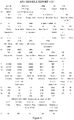
- FIG.4 is drawing illustrating an example of the A13 message of Airbus.
- A13 message mainly comprises 4 parts of information, which are: the message heading, APU record information, the operation parameters in starting of the aircraft engine and the start parameter of APU.
- the message heading is consisted of CC and C1 fields, and mainly includes the flight information of the aircraft, the segment wherein the message generated, the state of bleed valves, total air temperature (i.e. the outer temperature) and the like information.
- the APU record information is consisted of E1 field, comprising APU serial number, operation time and cycle and other information.
- the operation parameters in starting of the aircraft engine is consisted of N1 to S3 fields; wherein N1 and S1 represent the operation on the time of starting the first aircraft engine, N2 and S2 represent the operation on the time of starting the second aircraft engine, and N3 and S3 represent the slow-down state of APU after completing the starting of engine by APU.
- the APU operation parameters such as the start time STA, the highest exhaust gas temperature on start EGTP, the angle of inlet guide vane IGV and peak EGT rotation are all included in the existed A13 message. Therefore, the data acquired by the message can realize the monitoring of the malfunction of the APU turbine vane fracture and rotor shaft jam.
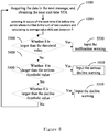
- Fig. 5 is a flow diagram illustrating the method for monitoring the APU turbine and rotor shaft jam according to one example of the present invention.
- start time STA is used.
- step 5100 acquiring the operation data of aircraft APU within a time period, which comprises but is not limited to the start time STA.
- the message in step 5100 can be acquired from the APU message.
- the control centre of Society International De Telecommunication Aeronautiques (SITA) and the control centre of Aviation Data Communication Corporation (ADCC) can obtain the message of the operation of the APU remotely in real-time, and decode the message of the APU operation modes by message decoder, and achieve the desired operation information of the aircraft APU.
- SITA Society International De Telecommunication Aeronautiques
- ADCC control centre of Aviation Data Communication Corporation
- step 5200 calculating the average value AVG and deviation ⁇ within the time period.
- step 5300 judging whether the deviation ⁇ obtained in step 5200 exceeds the failure threshold value. If exceeding the failure threshold value, input the failure warning in step 5310.
- step 5300 When the judgment in step 5300 is no, comparing whether the deviation ⁇ obtained in step 5200 exceeds the serious decline threshold value in step 5400. If exceeding the serious decline threshold value, input the serious decline warning in step 5410.
- step 5400 comparing whether the deviation ⁇ obtained in step 5200 exceeds the serious decline threshold value in step 5500. If exceeding the serious decline threshold value, input the serious decline warning in step 5510.
- the value of each threshold is a little different.
- the fluctuation when the APU of one type is in stable phase can be obtained, and the threshold values in other phases can be further estimated based on the fluctuation in stable phase as a standard.
- the decline threshold value is about 2 times of the fluctuation rate in stable phase
- the serious decline threshold value is about 4 times of the fluctuation rate in stable phase
- the failure threshold value is about 6 times of the fluctuation rate in stable phase.
- the method for analyzing the change trend by the updating data within a fixed time period can be called scrolled window method.
- the size of scrolled window i.e. the number M of points included within the range of calculating, depends on multiple factors, such as, the time interval of measurement, the control strategy and others. If the size is too small, the change of fluctuation is more easily influenced by the normal fluctuation, and more error messages will be generated, the effect of the invention will be affected finally. If the size is too large, although the change trend is still correct, this can decrease the timeliness of the invention, causing the warning information cannot be sent out timely. Therefore, the size of the scrolled window has an important effect on the invention.
- the value of M is about 30 in case of measuring 2-3 points daily.
- the value of M is about 20 in case of measuring no more than 2 point(s) daily.
- the intensive warnings if the intensive warnings occur in a time period, and returning to normal, then intensive warnings repeat, and returning to normal again, it can be judged that the malfunction of the APU turbine vane fracture and rotor shaft jam occurs.
- the said intensive warnings comprise continuous warnings over 3 times or warnings with interval less than a warning.
- the history data of STA in half of a year is obtained.
- the history data of STA in one year is obtained.
- Fig. 6 is a flow diagram illustrating the method for monitoring the APU turbine and rotor shaft jam according to another example of the present invention.
- only one parameter of start time STA is utilized.
- the difference between Fig. 6 and 5 is the algorithm for STA discrete degree.
- the discrete change of STA can be found quickly, but error message is apt to occur.
- the methods of the examples in Fig. 5 and 6 can be used in combination.
- the method 6000 for monitoring the malfunction of the APU turbine vane fracture and rotor shaft jam in step 6100, the method is performed by acquiring the operation data at some working time of aircraft APU, such as the start time STA, which is similar to the example shown in Fig. 5 .
- the desired information in step 6100 can be acquired by similar mode as step 5100.
- step 6200 selecting M values of the start time STA before the current time and calculating its average value AVG and deviation ⁇ . Calculation of the average value and deviation of a certain number of the previous points is to set a variation range for the next point which may be noise needs to be removed. According to the following description, one counter is used for recording the deviation point which changes beyond the preset range. When the number of times the deviation points appear continuously do not reach the number of warning, these deviation points are not counted into the range of samples calculating the average value and standard deviation. According to one example of the invention, the value of M can be 20.
- step 6300 comparing whether the deviation ⁇ obtained in the previous step exceeds the failure threshold value. If exceeding the failure threshold value, issuing the failure warning in step 6310.
- step 6400 When the judgment in step 6300 is no, entering step 6400, comparing whether the deviation ⁇ obtained in step 6200 exceeds the serious decline threshold value in step 6400. If exceeding the serious decline threshold value, input the serious decline warning in step 6410.
- step 6400 When the judgment in step 6400 is no, entering step 6500, comparing whether the deviation ⁇ obtained in step 6200 exceeds the serious decline threshold value in step 6500. If exceeding the serious decline threshold value, input the serious decline warning in step 6510.
- step 6500 When the judgment in step 6500 is no, entering step 6600, setting the counter to zero. This because that the deviation point is disconnected through the previous judgment. In order to calculating the number of the continuous deviation points, it is needed to set the counter to zero and recount.
- step 6700 judging whether the start time STA corresponding to the next data point is greater than AVG+n ⁇ or less than AVG-n ⁇ , wherein the value of n is determined by control strategy. If the value of n is high, the control of sudden-change points is looser, and error message can be reduced in this way, but the risk of failing to inform may exist; if the value of n is low, the control of sudden-change points is stricter, and the risk of failure can be avoided, but frequent warning might occur. Generally speaking, the value of n is between 1-5. According to one example of the invention, the value of n is 3.
- step 6700 If the judgment in step 6700 is yes, entering step 6710, the counter +1. In the next step, step 6720, judging whether the high threshold value counter is equal to the preset warning number Z. If the judgment is no, returning step 6700. If the judgment is yes, it demonstrates that the start time STA continuously reaches the preset warning number Z which exceeds the preset normal variation range and the temperature jumps upward. At this time, entering step 6730 and issuing the warning of jump change.
- warning signal can be output under the condition that a certain numbers being exceeded, to exclude the error message.
- the value of the preset warning number Z is related to control strategy, and is generally 2-5.
- step 6800 the counter is reverted to zero. This because that, if the number of continuously deviated points reaches the preset warning number, the occurrence of deviation points is not occasional, and the continuously deviated points cannot be excluded as noise. At this time, the counter is reverted to zero, and theses deviation points will be retained when entering into step 6200 in the next cycle, and will be taken into calculation. When this step is finished, returning to step 6100.
- acquiring the history data of STA in half of a year or in one year is obtained.
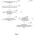
- Fig. 7 is a flow diagram illustrating the method for monitoring the APU turbine and rotor shaft jam according to yet another example of the present invention.
- the parameters the start time STA, exhausted gas temperature EGTA, the angle of inlet guide vane IGV and the temperature and rotation speed when EGT is at its peak are used.
- step 7100 the following operation information of aircraft APU is acquired: the start time STA, exhausted gas temperature EGTA, the angle of inlet guide vane IGV and the temperature and rotation speed when EGT is at its peak.
- the methods in example in Figs. 5 and 6 for acquiring the start time STA can also be used for acquiring the exhausted gas temperature EGTA, the angle of inlet guide vane IGV and the temperature and rotation speed when EGT is at its peak.
- step 7200 determining whether the start time STA is discrete.
- the method for determining whether the start time STA is discrete includes the examples of Figs.5 and 6 .
- the other methods can also be applied in step 7200 to determine whether the start time STA is discrete.
- step 7300 judging whether the highest exhaust gas temperature on start EGTP is close to or reaches the redline value. This demonstrates that in the case of decreased efficiency, APU increase the gasoline injection amount to maintain the input power.
- step 7400 calculating NPA, and judging whether NPA is reduced to the predetermined threshold value.
- the predetermined threshold value is about 35-40%.
- step 7500 if the exhausted gas temperature EGTP is close to or reaches the redline value and NPA is reduced to the predetermined threshold value, it can be judged that the malfunction of the APU turbine vane fracture and rotor shaft jam occurs.
- step 7600 judging whether the malfunction of the APU turbine vane fracture and rotor shaft jam occurs can be further judged by EGT and IGV.
- step 7600 judging whether the exhausted gas temperature EGT is close to or reaches the redline value or the angle of IGV increase or jump upward. This demonstrates that the exhausted gas temperature EGT reaches the redline value, and APU must increase the angle of IGV to reduce the input torque to ensure the constant rotation speed.
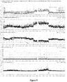
- Fig. 8 is a statistical data diagram recorded at the time of the APU turbine and rotor shaft jam according to one example of the present invention.
- the diamond marker represents replace of APU. It can be seen from Fig. 8 that the start time STA appears gradual raise as shown in solid line, and gradual restoration as shown in dotted line, and finally, closes to the final discrete state shown in diamond marker.
- Fig. 8 also shows that the highest exhaust gas temperature on start EGTP is close to redline value 840 degree, and NPA is close to or even exceeds the predetermined threshold value 35%.
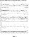
- Fig. 9 is a statistical data diagram of other operation parameters of APU in the example illustrated in Fig. 8 . As shown in Fig. 9 , EGTA is close to redline value, while IGV appears a upward jump.
- Fig. 10 is a statistical data diagram recorded at the time of the malfunction of the turbine vane fracture and casing jam according to one example of the present invention.
- the diamond marker represents replace of APU. It can be seen from Fig. 10 that the start time STA also becomes discrete, the highest exhaust gas temperature on start EGTP is close to redline value 840, and NPA is close to or even exceeds the predetermined threshold value 40%.
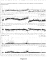
- Fig. 11 is a statistical data diagram of other operation parameters of APU in the example illustrated in Fig. 10 .
- EGTA decreases instead of being close to the redline value; and IGV is not adjusted.
- the actual condition is: the serious failure of the APU turbine vane fracture and rotor shaft jam occurs in this APU.
- Fig. 12 is a statistical data diagram recorded at the time of the malfunction of the turbine vane fracture and casing jam according to another example of the present invention.
- Fig. 12 shows more clearly the process that the start time STA raises gradually, returns to normal gradually, raises again gradually and returns to normal, and then disperse quickly, and finally is replaced.
- the example of Fig. 12 reflects the long-term regular of the change of STA, demonstrating the history data of STA is helpful for judging the malfunction of the APU turbine vane fracture and rotor shaft jam. This is beneficial to distinguishing the malfunction of the APU turbine vane fracture and rotor shaft jam with other malfunctions.
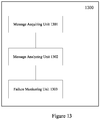
- Fig. 13 is a device for monitoring the malfunction of the turbine vane fracture and rotor shaft jam of aircraft auxiliary power unit APU according to one example of the present invention.
- the device 1300 for monitoring the malfunction of the turbine vane fracture and rotor shaft jam of airborne auxiliary power unit APU comprises: message acquiring unit 1301, which acquires the APU message within a time period; message analyzing unit 1302, which analyzing the desired APU operation data, the operation data at least comprises the start time STA; and failure monitoring unit 1303, which determines the circumstance of the APU turbine vane fracture and rotor shaft jam is in stable phase, decline phase, serious decline phase or malfunction phase according to the operation data of APU.
- a device for monitoring the circumstances of turbine vane fracture and rotor shaft jam of aircraft auxiliary power unit APU which comprises: a processor; and a memory linked with the processor, which stores the computer-readable codes; the computer-readable codes run in the processor to execute the following steps: acquiring the APU messages at multiple time points within a time period; obtaining the operation parameters of the APU according to the APU message, the operation parameters at least comprises start time STA; calculating the average value AVG and deviation index ⁇ of the start time STA within the time period; and determining that the circumstances of APU turbine vane fracture and rotor shaft jam is in stable phase, decline phase, serious decline phase or malfunction phase according to the deviation index ⁇ .
- the method and device for monitoring the malfunction of the APU turbine vane fracture and rotor shaft jam can find the malfunction of the turbine vane fracture and casing jam of APU before the occurrence of serious circumstances such as the stop of APU, and the replacement is taken. In this way, a large cost for maintenance and stock will be reduced, and the maintenance cycle will be shortened.
Landscapes
- Engineering & Computer Science (AREA)
- Chemical & Material Sciences (AREA)
- Combustion & Propulsion (AREA)
- General Physics & Mathematics (AREA)
- Physics & Mathematics (AREA)
- General Engineering & Computer Science (AREA)
- Mechanical Engineering (AREA)
- Automation & Control Theory (AREA)
- Aviation & Aerospace Engineering (AREA)
- Transportation (AREA)
- Manufacturing & Machinery (AREA)
- Life Sciences & Earth Sciences (AREA)
- Health & Medical Sciences (AREA)
- Analytical Chemistry (AREA)
- Biochemistry (AREA)
- General Health & Medical Sciences (AREA)
- Immunology (AREA)
- Pathology (AREA)
- Control Of Turbines (AREA)
- Testing Of Devices, Machine Parts, Or Other Structures Thereof (AREA)
- Control Of Positive-Displacement Air Blowers (AREA)
Applications Claiming Priority (1)
| Application Number | Priority Date | Filing Date | Title |
|---|---|---|---|
| CN201310313840.9A CN104344946B (zh) | 2013-07-24 | 2013-07-24 | Apu涡轮叶片断裂与转轴卡阻故障的监控方法和装置 |
Publications (2)
| Publication Number | Publication Date |
|---|---|
| EP2829688A1 EP2829688A1 (en) | 2015-01-28 |
| EP2829688B1 true EP2829688B1 (en) | 2019-01-16 |
Family
ID=51224787
Family Applications (1)
| Application Number | Title | Priority Date | Filing Date |
|---|---|---|---|
| EP14178425.6A Active EP2829688B1 (en) | 2013-07-24 | 2014-07-24 | Method and device for monitoring an APU turbine |
Country Status (10)
| Country | Link |
|---|---|
| US (1) | US9632010B2 (zh) |
| EP (1) | EP2829688B1 (zh) |
| JP (1) | JP6205321B2 (zh) |
| KR (1) | KR101998188B1 (zh) |
| CN (1) | CN104344946B (zh) |
| AU (1) | AU2014206179B2 (zh) |
| CA (1) | CA2857748C (zh) |
| HK (1) | HK1202330A1 (zh) |
| SG (1) | SG10201404370SA (zh) |
| TW (1) | TWI625273B (zh) |
Families Citing this family (10)
| Publication number | Priority date | Publication date | Assignee | Title |
|---|---|---|---|---|
| GB2518893B (en) * | 2013-10-07 | 2018-11-21 | Ge Aviat Systems Ltd | Method for predicting an auxiliary power unit fault |
| CA3000595A1 (en) | 2015-09-30 | 2017-04-06 | Bombardier Inc. | Method of and system for presenting an operating status of an aircraft engine |
| CN109313069B (zh) * | 2016-04-26 | 2021-08-03 | 比勒陀利亚大学 | 一种使用叶尖定时(btt)监测涡轮机转子叶片的方法和系统 |
| CN106226060B (zh) * | 2016-08-30 | 2019-02-05 | 成都飞亚航空设备应用研究所有限公司 | 飞机辅助动力装置测试系统 |
| KR20190021640A (ko) | 2017-08-23 | 2019-03-06 | 한화에어로스페이스 주식회사 | 인렛 가이드 베인 어셈블리 |
| CN110510147B (zh) * | 2019-08-02 | 2022-11-22 | 西安飞机工业(集团)有限责任公司 | 一种飞机结构裂纹检测方法 |
| CN110617115B (zh) * | 2019-10-29 | 2021-11-02 | 北京动力机械研究所 | 利用增材制造方式生产的涡轮发动机导流环组件 |
| CN111038714B (zh) * | 2019-11-28 | 2021-02-26 | 中国航空工业集团公司西安航空计算技术研究所 | 一种辅助动力装置超转检测装置及方法 |
| CN113291488B (zh) * | 2021-04-30 | 2022-01-04 | 浙江长龙航空有限公司 | 一种整体驱动发电机性能监控方法及装置 |
| CN116398257B (zh) * | 2023-04-12 | 2024-05-03 | 中国航发湖南动力机械研究所 | 一种航空涡轴发动机转子卡滞诊断方法及系统 |
Family Cites Families (11)
| Publication number | Priority date | Publication date | Assignee | Title |
|---|---|---|---|---|
| US6122575A (en) * | 1999-06-30 | 2000-09-19 | Hamilton Sundstrand Corporation | APU troubleshooting system |
| JP2005033559A (ja) * | 2003-07-14 | 2005-02-03 | Fuji Xerox Co Ltd | 故障診断装置 |
| US7364116B2 (en) * | 2004-09-27 | 2008-04-29 | The Boeing Company | Automatic control systems for aircraft auxiliary power units, and associated methods |
| US7693643B2 (en) * | 2005-02-14 | 2010-04-06 | Honeywell International Inc. | Fault detection system and method for turbine engine fuel systems |
| US7369932B2 (en) | 2006-05-04 | 2008-05-06 | Honeywell International, Inc. | System and method for turbine engine fault detection using discrete event system modeling |
| US8116932B2 (en) * | 2009-02-25 | 2012-02-14 | GM Global Technology Operations LLC | Auxiliary pump diagnostic systems and methods |
| US8471702B2 (en) * | 2010-12-22 | 2013-06-25 | General Electric Company | Method and system for compressor health monitoring |
| CN102320382A (zh) * | 2011-07-07 | 2012-01-18 | 中国国际航空股份有限公司 | 飞机性能检测方法 |
| CN102343983A (zh) * | 2011-07-07 | 2012-02-08 | 中国国际航空股份有限公司 | 飞机apu性能检测方法 |
| CN102416821A (zh) * | 2011-07-27 | 2012-04-18 | 中国国际航空股份有限公司 | 飞机系统数据处理方法 |
| ITCO20120008A1 (it) * | 2012-03-01 | 2013-09-02 | Nuovo Pignone Srl | Metodo e sistema per monitorare la condizione di un gruppo di impianti |
-
2013
- 2013-07-24 CN CN201310313840.9A patent/CN104344946B/zh active Active
-
2014
- 2014-07-23 CA CA2857748A patent/CA2857748C/en active Active
- 2014-07-23 US US14/339,350 patent/US9632010B2/en active Active
- 2014-07-24 KR KR1020140093939A patent/KR101998188B1/ko active IP Right Grant
- 2014-07-24 AU AU2014206179A patent/AU2014206179B2/en active Active
- 2014-07-24 TW TW103125397A patent/TWI625273B/zh active
- 2014-07-24 JP JP2014151133A patent/JP6205321B2/ja active Active
- 2014-07-24 SG SG10201404370SA patent/SG10201404370SA/en unknown
- 2014-07-24 EP EP14178425.6A patent/EP2829688B1/en active Active
-
2015
- 2015-03-17 HK HK15102745.7A patent/HK1202330A1/zh unknown
Non-Patent Citations (1)
| Title |
|---|
| None * |
Also Published As
| Publication number | Publication date |
|---|---|
| JP2015038348A (ja) | 2015-02-26 |
| SG10201404370SA (en) | 2015-02-27 |
| US9632010B2 (en) | 2017-04-25 |
| AU2014206179B2 (en) | 2017-12-21 |
| CA2857748A1 (en) | 2015-01-24 |
| KR101998188B1 (ko) | 2019-07-09 |
| TWI625273B (zh) | 2018-06-01 |
| CN104344946B (zh) | 2017-12-05 |
| JP6205321B2 (ja) | 2017-09-27 |
| EP2829688A1 (en) | 2015-01-28 |
| AU2014206179A1 (en) | 2015-02-12 |
| TW201515933A (zh) | 2015-05-01 |
| HK1202330A1 (zh) | 2015-09-25 |
| KR20150012217A (ko) | 2015-02-03 |
| CA2857748C (en) | 2019-08-20 |
| US20150068293A1 (en) | 2015-03-12 |
| CN104344946A (zh) | 2015-02-11 |
Similar Documents
| Publication | Publication Date | Title |
|---|---|---|
| EP2829688B1 (en) | Method and device for monitoring an APU turbine | |
| CA2782276C (en) | Method for detecting whether performance of aircraft components is in the decline period | |
| AU2012204020B2 (en) | Method for detecting the performance of auxiliary power unit | |
| AU2014206172B2 (en) | Method and Apparatus for Detecting Performance of an APU Starter | |
| AU2014206178B2 (en) | Method and Apparatus for Detecting Performance of an APU Fuel Assembly | |
| AU2014206182B2 (en) | Method and apparatus for monitoring efficiency of aircraft auxiliary power unit |
Legal Events
| Date | Code | Title | Description |
|---|---|---|---|
| 17P | Request for examination filed |
Effective date: 20140724 |
|
| AK | Designated contracting states |
Kind code of ref document: A1 Designated state(s): AL AT BE BG CH CY CZ DE DK EE ES FI FR GB GR HR HU IE IS IT LI LT LU LV MC MK MT NL NO PL PT RO RS SE SI SK SM TR |
|
| AX | Request for extension of the european patent |
Extension state: BA ME |
|
| PUAI | Public reference made under article 153(3) epc to a published international application that has entered the european phase |
Free format text: ORIGINAL CODE: 0009012 |
|
| R17P | Request for examination filed (corrected) |
Effective date: 20150625 |
|
| RBV | Designated contracting states (corrected) |
Designated state(s): AL AT BE BG CH CY CZ DE DK EE ES FI FR GB GR HR HU IE IS IT LI LT LU LV MC MK MT NL NO PL PT RO RS SE SI SK SM TR |
|
| STAA | Information on the status of an ep patent application or granted ep patent |
Free format text: STATUS: EXAMINATION IS IN PROGRESS |
|
| 17Q | First examination report despatched |
Effective date: 20180104 |
|
| GRAP | Despatch of communication of intention to grant a patent |
Free format text: ORIGINAL CODE: EPIDOSNIGR1 |
|
| STAA | Information on the status of an ep patent application or granted ep patent |
Free format text: STATUS: GRANT OF PATENT IS INTENDED |
|
| INTG | Intention to grant announced |
Effective date: 20180919 |
|
| GRAS | Grant fee paid |
Free format text: ORIGINAL CODE: EPIDOSNIGR3 |
|
| GRAA | (expected) grant |
Free format text: ORIGINAL CODE: 0009210 |
|
| STAA | Information on the status of an ep patent application or granted ep patent |
Free format text: STATUS: THE PATENT HAS BEEN GRANTED |
|
| AK | Designated contracting states |
Kind code of ref document: B1 Designated state(s): AL AT BE BG CH CY CZ DE DK EE ES FI FR GB GR HR HU IE IS IT LI LT LU LV MC MK MT NL NO PL PT RO RS SE SI SK SM TR |
|
| REG | Reference to a national code |
Ref country code: GB Ref legal event code: FG4D |
|
| REG | Reference to a national code |
Ref country code: CH Ref legal event code: EP |
|
| REG | Reference to a national code |
Ref country code: IE Ref legal event code: FG4D |
|
| REG | Reference to a national code |
Ref country code: DE Ref legal event code: R096 Ref document number: 602014039912 Country of ref document: DE |
|
| REG | Reference to a national code |
Ref country code: AT Ref legal event code: REF Ref document number: 1089852 Country of ref document: AT Kind code of ref document: T Effective date: 20190215 |
|
| REG | Reference to a national code |
Ref country code: NL Ref legal event code: MP Effective date: 20190116 |
|
| REG | Reference to a national code |
Ref country code: LT Ref legal event code: MG4D |
|
| PG25 | Lapsed in a contracting state [announced via postgrant information from national office to epo] |
Ref country code: NL Free format text: LAPSE BECAUSE OF FAILURE TO SUBMIT A TRANSLATION OF THE DESCRIPTION OR TO PAY THE FEE WITHIN THE PRESCRIBED TIME-LIMIT Effective date: 20190116 |
|
| REG | Reference to a national code |
Ref country code: AT Ref legal event code: MK05 Ref document number: 1089852 Country of ref document: AT Kind code of ref document: T Effective date: 20190116 |
|
| PG25 | Lapsed in a contracting state [announced via postgrant information from national office to epo] |
Ref country code: PT Free format text: LAPSE BECAUSE OF FAILURE TO SUBMIT A TRANSLATION OF THE DESCRIPTION OR TO PAY THE FEE WITHIN THE PRESCRIBED TIME-LIMIT Effective date: 20190516 Ref country code: NO Free format text: LAPSE BECAUSE OF FAILURE TO SUBMIT A TRANSLATION OF THE DESCRIPTION OR TO PAY THE FEE WITHIN THE PRESCRIBED TIME-LIMIT Effective date: 20190416 Ref country code: FI Free format text: LAPSE BECAUSE OF FAILURE TO SUBMIT A TRANSLATION OF THE DESCRIPTION OR TO PAY THE FEE WITHIN THE PRESCRIBED TIME-LIMIT Effective date: 20190116 Ref country code: SE Free format text: LAPSE BECAUSE OF FAILURE TO SUBMIT A TRANSLATION OF THE DESCRIPTION OR TO PAY THE FEE WITHIN THE PRESCRIBED TIME-LIMIT Effective date: 20190116 Ref country code: PL Free format text: LAPSE BECAUSE OF FAILURE TO SUBMIT A TRANSLATION OF THE DESCRIPTION OR TO PAY THE FEE WITHIN THE PRESCRIBED TIME-LIMIT Effective date: 20190116 Ref country code: ES Free format text: LAPSE BECAUSE OF FAILURE TO SUBMIT A TRANSLATION OF THE DESCRIPTION OR TO PAY THE FEE WITHIN THE PRESCRIBED TIME-LIMIT Effective date: 20190116 Ref country code: LT Free format text: LAPSE BECAUSE OF FAILURE TO SUBMIT A TRANSLATION OF THE DESCRIPTION OR TO PAY THE FEE WITHIN THE PRESCRIBED TIME-LIMIT Effective date: 20190116 |
|
| PG25 | Lapsed in a contracting state [announced via postgrant information from national office to epo] |
Ref country code: RS Free format text: LAPSE BECAUSE OF FAILURE TO SUBMIT A TRANSLATION OF THE DESCRIPTION OR TO PAY THE FEE WITHIN THE PRESCRIBED TIME-LIMIT Effective date: 20190116 Ref country code: LV Free format text: LAPSE BECAUSE OF FAILURE TO SUBMIT A TRANSLATION OF THE DESCRIPTION OR TO PAY THE FEE WITHIN THE PRESCRIBED TIME-LIMIT Effective date: 20190116 Ref country code: HR Free format text: LAPSE BECAUSE OF FAILURE TO SUBMIT A TRANSLATION OF THE DESCRIPTION OR TO PAY THE FEE WITHIN THE PRESCRIBED TIME-LIMIT Effective date: 20190116 Ref country code: IS Free format text: LAPSE BECAUSE OF FAILURE TO SUBMIT A TRANSLATION OF THE DESCRIPTION OR TO PAY THE FEE WITHIN THE PRESCRIBED TIME-LIMIT Effective date: 20190516 Ref country code: GR Free format text: LAPSE BECAUSE OF FAILURE TO SUBMIT A TRANSLATION OF THE DESCRIPTION OR TO PAY THE FEE WITHIN THE PRESCRIBED TIME-LIMIT Effective date: 20190417 Ref country code: BG Free format text: LAPSE BECAUSE OF FAILURE TO SUBMIT A TRANSLATION OF THE DESCRIPTION OR TO PAY THE FEE WITHIN THE PRESCRIBED TIME-LIMIT Effective date: 20190416 |
|
| REG | Reference to a national code |
Ref country code: DE Ref legal event code: R097 Ref document number: 602014039912 Country of ref document: DE |
|
| PG25 | Lapsed in a contracting state [announced via postgrant information from national office to epo] |
Ref country code: IT Free format text: LAPSE BECAUSE OF FAILURE TO SUBMIT A TRANSLATION OF THE DESCRIPTION OR TO PAY THE FEE WITHIN THE PRESCRIBED TIME-LIMIT Effective date: 20190116 Ref country code: RO Free format text: LAPSE BECAUSE OF FAILURE TO SUBMIT A TRANSLATION OF THE DESCRIPTION OR TO PAY THE FEE WITHIN THE PRESCRIBED TIME-LIMIT Effective date: 20190116 Ref country code: DK Free format text: LAPSE BECAUSE OF FAILURE TO SUBMIT A TRANSLATION OF THE DESCRIPTION OR TO PAY THE FEE WITHIN THE PRESCRIBED TIME-LIMIT Effective date: 20190116 Ref country code: EE Free format text: LAPSE BECAUSE OF FAILURE TO SUBMIT A TRANSLATION OF THE DESCRIPTION OR TO PAY THE FEE WITHIN THE PRESCRIBED TIME-LIMIT Effective date: 20190116 Ref country code: AT Free format text: LAPSE BECAUSE OF FAILURE TO SUBMIT A TRANSLATION OF THE DESCRIPTION OR TO PAY THE FEE WITHIN THE PRESCRIBED TIME-LIMIT Effective date: 20190116 Ref country code: CZ Free format text: LAPSE BECAUSE OF FAILURE TO SUBMIT A TRANSLATION OF THE DESCRIPTION OR TO PAY THE FEE WITHIN THE PRESCRIBED TIME-LIMIT Effective date: 20190116 Ref country code: AL Free format text: LAPSE BECAUSE OF FAILURE TO SUBMIT A TRANSLATION OF THE DESCRIPTION OR TO PAY THE FEE WITHIN THE PRESCRIBED TIME-LIMIT Effective date: 20190116 Ref country code: SK Free format text: LAPSE BECAUSE OF FAILURE TO SUBMIT A TRANSLATION OF THE DESCRIPTION OR TO PAY THE FEE WITHIN THE PRESCRIBED TIME-LIMIT Effective date: 20190116 |
|
| PLBE | No opposition filed within time limit |
Free format text: ORIGINAL CODE: 0009261 |
|
| STAA | Information on the status of an ep patent application or granted ep patent |
Free format text: STATUS: NO OPPOSITION FILED WITHIN TIME LIMIT |
|
| PG25 | Lapsed in a contracting state [announced via postgrant information from national office to epo] |
Ref country code: SM Free format text: LAPSE BECAUSE OF FAILURE TO SUBMIT A TRANSLATION OF THE DESCRIPTION OR TO PAY THE FEE WITHIN THE PRESCRIBED TIME-LIMIT Effective date: 20190116 |
|
| 26N | No opposition filed |
Effective date: 20191017 |
|
| PG25 | Lapsed in a contracting state [announced via postgrant information from national office to epo] |
Ref country code: MC Free format text: LAPSE BECAUSE OF FAILURE TO SUBMIT A TRANSLATION OF THE DESCRIPTION OR TO PAY THE FEE WITHIN THE PRESCRIBED TIME-LIMIT Effective date: 20190116 Ref country code: SI Free format text: LAPSE BECAUSE OF FAILURE TO SUBMIT A TRANSLATION OF THE DESCRIPTION OR TO PAY THE FEE WITHIN THE PRESCRIBED TIME-LIMIT Effective date: 20190116 |
|
| REG | Reference to a national code |
Ref country code: CH Ref legal event code: PL |
|
| PG25 | Lapsed in a contracting state [announced via postgrant information from national office to epo] |
Ref country code: TR Free format text: LAPSE BECAUSE OF FAILURE TO SUBMIT A TRANSLATION OF THE DESCRIPTION OR TO PAY THE FEE WITHIN THE PRESCRIBED TIME-LIMIT Effective date: 20190116 |
|
| REG | Reference to a national code |
Ref country code: BE Ref legal event code: MM Effective date: 20190731 |
|
| PG25 | Lapsed in a contracting state [announced via postgrant information from national office to epo] |
Ref country code: BE Free format text: LAPSE BECAUSE OF NON-PAYMENT OF DUE FEES Effective date: 20190731 Ref country code: CH Free format text: LAPSE BECAUSE OF NON-PAYMENT OF DUE FEES Effective date: 20190731 Ref country code: LU Free format text: LAPSE BECAUSE OF NON-PAYMENT OF DUE FEES Effective date: 20190724 Ref country code: LI Free format text: LAPSE BECAUSE OF NON-PAYMENT OF DUE FEES Effective date: 20190731 |
|
| PG25 | Lapsed in a contracting state [announced via postgrant information from national office to epo] |
Ref country code: IE Free format text: LAPSE BECAUSE OF NON-PAYMENT OF DUE FEES Effective date: 20190724 |
|
| PG25 | Lapsed in a contracting state [announced via postgrant information from national office to epo] |
Ref country code: CY Free format text: LAPSE BECAUSE OF FAILURE TO SUBMIT A TRANSLATION OF THE DESCRIPTION OR TO PAY THE FEE WITHIN THE PRESCRIBED TIME-LIMIT Effective date: 20190116 |
|
| PG25 | Lapsed in a contracting state [announced via postgrant information from national office to epo] |
Ref country code: HU Free format text: LAPSE BECAUSE OF FAILURE TO SUBMIT A TRANSLATION OF THE DESCRIPTION OR TO PAY THE FEE WITHIN THE PRESCRIBED TIME-LIMIT; INVALID AB INITIO Effective date: 20140724 Ref country code: MT Free format text: LAPSE BECAUSE OF FAILURE TO SUBMIT A TRANSLATION OF THE DESCRIPTION OR TO PAY THE FEE WITHIN THE PRESCRIBED TIME-LIMIT Effective date: 20190116 |
|
| PG25 | Lapsed in a contracting state [announced via postgrant information from national office to epo] |
Ref country code: MK Free format text: LAPSE BECAUSE OF FAILURE TO SUBMIT A TRANSLATION OF THE DESCRIPTION OR TO PAY THE FEE WITHIN THE PRESCRIBED TIME-LIMIT Effective date: 20190116 |
|
| PGFP | Annual fee paid to national office [announced via postgrant information from national office to epo] |
Ref country code: GB Payment date: 20230504 Year of fee payment: 10 |
|
| PGFP | Annual fee paid to national office [announced via postgrant information from national office to epo] |
Ref country code: DE Payment date: 20230426 Year of fee payment: 10 |
|
| PGFP | Annual fee paid to national office [announced via postgrant information from national office to epo] |
Ref country code: FR Payment date: 20240619 Year of fee payment: 11 |