EP2829659B1 - Dispositif antennaire et plaque surélevée - Google Patents
Dispositif antennaire et plaque surélevée Download PDFInfo
- Publication number
- EP2829659B1 EP2829659B1 EP14176894.5A EP14176894A EP2829659B1 EP 2829659 B1 EP2829659 B1 EP 2829659B1 EP 14176894 A EP14176894 A EP 14176894A EP 2829659 B1 EP2829659 B1 EP 2829659B1
- Authority
- EP
- European Patent Office
- Prior art keywords
- stand
- antenna assembly
- antenna
- tire
- Prior art date
- Legal status (The legal status is an assumption and is not a legal conclusion. Google has not performed a legal analysis and makes no representation as to the accuracy of the status listed.)
- Active
Links
Images


Classifications
-
- G—PHYSICS
- G06—COMPUTING OR CALCULATING; COUNTING
- G06K—GRAPHICAL DATA READING; PRESENTATION OF DATA; RECORD CARRIERS; HANDLING RECORD CARRIERS
- G06K7/00—Methods or arrangements for sensing record carriers, e.g. for reading patterns
- G06K7/10—Methods or arrangements for sensing record carriers, e.g. for reading patterns by electromagnetic radiation, e.g. optical sensing; by corpuscular radiation
- G06K7/10009—Methods or arrangements for sensing record carriers, e.g. for reading patterns by electromagnetic radiation, e.g. optical sensing; by corpuscular radiation sensing by radiation using wavelengths larger than 0.1 mm, e.g. radio-waves or microwaves
- G06K7/10316—Methods or arrangements for sensing record carriers, e.g. for reading patterns by electromagnetic radiation, e.g. optical sensing; by corpuscular radiation sensing by radiation using wavelengths larger than 0.1 mm, e.g. radio-waves or microwaves using at least one antenna particularly designed for interrogating the wireless record carriers
-
- H—ELECTRICITY
- H01—ELECTRIC ELEMENTS
- H01Q—ANTENNAS, i.e. RADIO AERIALS
- H01Q1/00—Details of, or arrangements associated with, antennas
- H01Q1/12—Supports; Mounting means
- H01Q1/22—Supports; Mounting means by structural association with other equipment or articles
- H01Q1/2208—Supports; Mounting means by structural association with other equipment or articles associated with components used in interrogation type services, i.e. in systems for information exchange between an interrogator/reader and a tag/transponder, e.g. in Radio Frequency Identification [RFID] systems
- H01Q1/2241—Supports; Mounting means by structural association with other equipment or articles associated with components used in interrogation type services, i.e. in systems for information exchange between an interrogator/reader and a tag/transponder, e.g. in Radio Frequency Identification [RFID] systems used in or for vehicle tyres
Definitions
- the invention relates generally to a drive-over stand and antenna assembly for receiving data from a vehicle and more specifically to RFID device readers and an antenna assembly for a reader of RFID devices mounted to the wheel units of a vehicle.
- Radio frequency identification devices are useful in association with sundry product categories and have gained widespread commercial importance and acceptance. Such devices generally have memory storage capability for electronically storing product-specific information such as product history and a product identification number.
- the device further provides an integrated transmitter that transmits responsive to a prompt signal the stored data for receipt by a receiver antenna. For example, it is known to associate an RFID with a vehicle tire or wheel rim assembly in order to access tire, vehicle, and/or wheel related identification and history throughout the lifetime service of the product.
- EP-A-2 339 692 describes a stand and antenna assembly in accordance with the preamble of claim 1. A similar assembly is also known from US-A-2011/148593 .
- US-A-2007/0018805 describes a remote interrogation of a vehicle wheel.
- An apparatus comprising a plurality of antennas for transmitting an interrogation signal to a sensor mounted to a wheel.
- EP-A-2 202 099 describes a RFID enabled tire control system and method comprising a tire-based RFID tag mounted to the tire and a pass-through portal operatively entered and exited by the vehicle. At least one antenna is positioned within the portal and at least one RFID reader is coupled to the antenna.
- WO-A-2005/036694 describes an antenna system embedded in a support structure for interrogating a tire sensor transponder.
- the invention relates to a stand and antenna assembly in accordance with claim 1.
- a stand and antenna assembly having a lead-on ramped surface and an exit-off ramped surface aligned and operative to intercept and engage the vehicle tire as the vehicle tire traverses over the upper surface of the stand.
- a pocket is disposed within the stand base configured for receiving an antenna assembly.
- An antenna assembly is positioned within the pocket of the base, seated at a tilt angle operative to direct a read field toward a vehicle approach path to the stand.
- the antenna assembly may be constructed as a planar panel body, a plane of the planar panel body tilting at the tilt angle toward the vehicle approach path.
- the stand is constructed having two pockets formed within the base, with two antenna assemblies seated respectively within the pockets at a respective tilt angle.
- the first antenna assembly directs a read field toward a vehicle approach path to the stand and the second antenna assembly directs a second read field toward a vehicle exit path from the stand.
- One or more additional antenna assemblies are mounted within the base of the stand, adapted to receive antenna assembly(s) and to direct a read field to an intermediate region between the lead-on and the exit-off ramps.
- the stand may be assembled from a modular array of stand components mutually connected together by keying and interlocking protrusions.
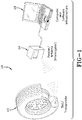
- a tire-based RFID system 10 is shown in which a tire 12 is provided with a tag or transponder 14.
- the transponder 14 functionally operates to transmit by radio frequency tire identification information to a remote reader or antenna 16 interrogator.
- the interrogator 16 provides the information to a computer and software infrastructure 18 which can thereby track the tire, its usage, and history throughout the useful life of the tire.
- the transponder 14 may be affixed at any suitable location and manner to the tire as shown in FIG. 2 , such as on the tire rim (position A); the tire inner sidewall surface (position B); or the tire inner tread region surface (position C).
- the transponder 14 may further have additional sensors incorporated therein such as temperature or pressure monitoring sensors. Data from such sensors may likewise be transmitted to the remote reader 16 and used to monitor the status of tire 12.
- a stand component or section 20 is shown.
- the drive over stand of the subject disclosure may constitute a single unitary body such as that shown in FIG. 3 , or a modular array of interconnected bodies or sections, depending on the preference of the user and/or the size and configuration of the drive over stand for its intended application.
- the following description of the component or section 20 in FIGS. 3, 4 and 5 has application in both the single, unitary stand embodiment and the modular, multi-section embodiment of the invention.
- the stand component 20 is formed from a suitably strong, RF signal transparent material, such as plastic.
- the stand 20 has a forward inclined ramp surface 22 that extends from a forward, ground-level edge 38 to a flat adjacent surface 26.
- the shape of the stand component 20 is generally rectangular in plan, but may be formed in other geometric configurations such as a square.
- the stand component or section 20 includes sidewalls 28 extending from a bottom support surface 30 to the planar, flat top surface 26.
- Formed within the underside of the component 20 is a matrix or grid 32 of intersecting lateral and longitudinal ribs or flanges 34, 36.
- the reinforcement grid 32 extends from the forward edge 38 of the component 20 to a rearward wall 39 of the strand component 20 and serves to provide supporting strength to the stand with which to support a vehicle traversing the stand upper surface.
- the grid formed by ribs or flanges 34, 36 is preferably integrally created by a conventional molding process used in the creation of the stand component 20.
- a pocket, receptacle, or chamber 40 within the reinforcement grid 32 during the molding of the stand component 20.
- the pocket 40 is sized and shaped to accommodate seating receipt of a read antenna assembly as will be explained.
- the pocket 40 as shown in FIG. 4 , is positioned below the flat surface 26 of the stand, centered between stand sides 28.
- the pocket 40 is configured in section having an angled or sloped internal floor surface by which the read antenna assembly positioned in the pocket is tilted at a preferred directed angle.
- the stand component 20 is further provided with an interlock feature that enables multiple stand components 20 to be interconnected in an array.
- a key slot 42 and protrusion 44 is formed in each side 28 of the stand in spaced apart relation as a similarly paired key slot 46 and key protrusion 48 is formed in the rear wall 39.
- the stand accepts within pocket 40 an antenna assembly 50 as shown in FIG. 50 with associate screw hardware 52 used to affix the antenna assembly 50 within the pocket 40.
- the antenna assembly 50 is in a panel configuration, incorporating read antenna within a substrate panel. As assembled, the antenna assembly 50 is generally rectangular and of complementary dimension and shape as the pocket 40 for close-fit insertion and seating.
- FIG. 5 it will be appreciated that multiple pockets are provided, each having an associated field-aimed read antenna assembly. Multiple antennae may be used to adjust the sensitivity and read-efficiency of the system in reading an RF signal from a vehicle passing over the stand.
- the stand operates as a speed control mechanism that slows the vehicle speed over the stand for optimal RFID read efficiency.
- an exemplary second antenna assembly panel 54 is received into a second pocket 56 formed within the stand 20.
- the second pocket 56 is located to the rear of the first pocket 40 and the second antenna assembly panel 54 is positioned and secured within the second pocket 56.
- the second panel and antenna 54 is tilted by the inward angled floor surface of the second pocket 56 so as to aim the second antenna 54 toward a preferred region of the upper surface 22 of the stand.
- FIG. 6 shows the completed assembly of the two antenna system into the underside of the stand 22.
- FIG. 7 shows in phantom the top plan view of the stand 22 with the two antenna panels 50, 54 in their relative positions respectively below the top surface of the stand.
- FIG. 8 the respective tilt angles and direction of the antenna panels 50, 54 are shown with the rearward antenna 54 aimed toward the rear of the top surface 26 of the stand 22 and the forward antenna 50 aimed toward the forward end and ramped surface 24 of the stand.
- the read fields of the antenna assemblies 50, 54 consequently are directed and aimed at respective regions of the stand upper surface 24 so as to read a vehicle tire-based RFID tag passing across the stand upper surface at a reduced rate of speed imposed by the stand convex upper surface.
- the degree of convexity of the upper stand surface may be adjusted to slow the vehicle down to an optimal RFID-read rate of speed. Together with a proper location of the pockets, the tilt angle of the read antennae within the pockets, and an appropriate angled directional aiming of the read fields provided by the antenna or antennae, a reliable and predictable reading of the tire-based RFID tag may be achieved.
- the reading of the tire-based RFID tag will preferably be initiated and continue as the vehicle approaches, passes over and exits the stand 20. It will further be appreciated that, while only a forward ramped surface 24 is shown in the stand section 20, an exit ramp would be present in an actual stand suitable for field use.
- the antennae 50, 54 due to appropriate tilting by the pocket configuration in which each is seated, may be directed in a forward or rearward direction so as to read the tag on a tire as the tire approaches the stand along an approach path; engages and travels over the stand upper surface 22, and as the tire exits off the stand along an exit path.
- an array of stand components or sections 20 may be constructed into a larger stand configuration by interlocking protrusions 44 and slots 42 in sides and ends of the stand sections into complementary protrusions and slots of adjacent stand sections.
- the stand sections 20 are configured to provide a ramped on-surface 24 and a ramped off surface 25 with the flat surfaces 26 of each section forming an intermediate flat surface between the ramped surfaces (comparative example).
- the array stand configuration 58 formed from multiple stand sections 20 forms a suitably wide and long upper surface 26.
- FIG. 11 shows an array configured stand 58 formed from two sections 20 (comparative example).
- Four of the stands 58 are placed apart within in read station on the ground surface at a spacing designed to intercept the tires of a vehicle 64.
- a single stand large enough to accommodate all of the wheels of a vehicle may be constructed and used, the stand having read fields created by pocket-residing multiple antenna mountings within the single stand.
- the stands 58 are suitably wide and long to intercept the passenger tires as the vehicle 64 passes through the read station.
- the convex upper drive-over surface 22 of each stand operates to slow the vehicle speed to an optimal RFID tag read-speed.
- the length of the stands 58 is such that a complete revolution of each tire will occur as the vehicle passes over the stands, further ensuring a positive reading of the RFID tag of each tire.
- the stand antennae are wired by conductors 60, 62 to an RFID signal reader 16 which uploads RFID data to a computer 18, preferably by wireless transmission.
- FIGS. 12 and 13 a larger stand array may be constructed as shown in FIGS. 12 and 13 (comparative example).
- a three section stand is created by connecting three stand components 20 together as shown. The lengthwise size of each component 20 may be adjusted to create a stand 58 of sufficient length so as to ensure a complete revolution of the larger truck tire 12 over the stand surface 22. A positive and accurate reading of the RFID tag 14 mounted to each tire results.
- the wider stand provides antennae beneath each of the tandem tires as the tires pass over a stand. A simultaneous reading of both tires may be effected by appropriate aiming of the field generated by antennae within the pockets(s) of each stand component.
- FIG. 14 illustrates the directional aiming of read-fields from the antennae 50 within stand component pockets toward each of the tandem tires 12.
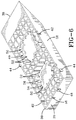
- FIGS. 15A through 15C show a comparative example of a drive-over stand 68 in an array configuration.
- the stand 68 is constructed by a set of components 20 assembled together end to end to define a V-channel 70.
- the trailing or exit ramped surfaces 25 of the forward stand components combine with the lead-on or entry ramped surfaces 24 of the rearward stand components to define the V-channel 70 therebetween.
- the antennae 50, 54 mounted within underside pockets within the stand components are tilted and aimed directionally toward the ramped surfaces 25, 24 defining V-channel 70.
- a vehicle traversing over the upper surface 22 of the stand array 68 will slow down in speed as the tires encounter the lead-on ramped surfaces 24A of the first line of stand components 20, then travel across the flat surface 26.
- the vehicle will then slow further as the tires enter into the V-channel 70 from the first line of ramped exit surfaces 25A.
- the vehicle will then slow still further as the vehicle encounters the second line of lead-on ramped surfaces 24B and finally exits from the second line of exit ramped surfaces 25B.
- Directional antenna read-fields are directed toward the tires of the vehicle as they encounter the ramped surfaces 24A, 25A, 24B and 25B, ensuring a positive reading of the RFID tags mounted to the tires.
- additional lines of stand components or sections may be added by protrusion and slot connection to the array of FIG. 15A if desired.
- a sequence of V-shaped channels in the elongated stand may thus be created to further reduce the vehicle's speed over the stand and provide additional lines of antennae mounted within component pockets with which to effect a reading of the RFID tags.
- the modularity of the stand sections or components facilitates and offers flexibility in the stand configuration that can meet the needs of the application or user.
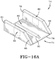
- FIGS 16A through FIG. 16C Another comparative example of a drive over stand 74 is shown in FIGS 16A through FIG. 16C .
- the stand 74 is configured having a floor76, parallel opposite side walls 78, 80, open ends and a through channel 82 between the side walls 78, 80.
- RFID tag reading antennae 84, 86 mount to the side walls 78, 80 and direct an aimed read-field into the channel 82.
- the forward edges 88 of the side walls 78, 80 and a dividing rib 90 extends longitudinally along the floor surface 76 of the stand, projecting upward into channel 82.
- FIGS. 16B and 16C a vehicle tire 12 carrying an RFID tag 14 is driven through the channel 82 with the stand 74 positioned on a ground surface in alignment with the tire.
- the read fields generated from the read antennae 84, 86 and directed into the channel 82 function to read the RFID tire-based tags as the tire passes through the channel 82.
- the divider rib 90 operates to align the tires within the channel 82 as the tires are driven through the stand.
- the stand 74 effectively reads the RFID tags as the tire passes through.
- stand 74 lacks the speed reduction capability afforded by the convex stand embodiments previously described.
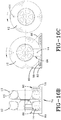
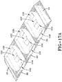
- a comparative example is shown in which a pocket-based antennae 100, 102, 104, 106 are mounded at a tilt angle in multiple stand components 94, 96, 98 connected in series.
- the antennae are arranged in an alternative, transverse linear pattern across a respective stand component.
- Each antennae 100, 102 , 104, 106 is tilted within a respective underside pocket at a preferred tilt angle that aims the read field of each antenna in a preferred direction.
- Each antenna is thus positioned to direct its read field toward the tire RFID tag passing over the stand surface.
- Antenna 102, 104 angle inward toward each other and face toward opposite sides of the stand component.
- FIGS. 17B and 17C illustrate a tandem truck tire pairing passing over the stand with the transverse linear array of antennae 100, 102, 104, 106 in a read mode.
- the end stand sections 94, 96 are ramped and connect to a non-ramped intermediate stand section 98. More sections may be incorporated to elongate the stand, if desired, to subject the tire RFID tags to more read fields as the tire traverses over the stand.
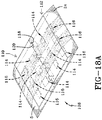
- an alternative stand configuration 108 employing alternative interconnection means for connecting stand sections 110, 112 together (comparative example).
- the stand sections 110, 112 are provided with antenna 114, 116 mounted within section pockets as described previously.
- the antennae 114, 116 are shown in the transverse linear configuration across each stand component 110, 112 but may be configured in a front to back orientation as described previously.
- the stand sections 110, 112 employ a dovetail joint to interconnect together.
- Dovetail projections 120 along a rearward side of each section fit into dovetail slots 118 of the opposite stand component to detachably interconnect the two components 110, 112 together.
- Ramps 24, 25 of the connected components form the forward lead-on and exit off ramps for vehicles driving over the stand 108.
- the drive-over stand of the subject invention provides internal pockets formed within the stand and below a drive over surface 22.
- the pockets are placed in strategic locations and receive antenna devices, preferably in form of an antenna panel therein.
- the pockets orient and aim the seated antenna panels to preferred drive over surface regions, by tilting or angling the antenna panels at respective tilt angles.
- the tilt angle between the plane of the antenna panel to a bottom surface of the stand is preferably within a range of 13 to 15 degrees
- the tilt of an antenna panel forward, toward a forward stand ramped entry surface, and an antenna panel rearward toward a rearward ramped exit surface allows the directed read fields from the antenna panels to interrogate and read the tire-based RFID tags as the tire approaches the stand along an approach path, and to interrogate and continue to read the tire-based RFID tags after the tire exits from the stand along an exit path.
- Additional pocket-seated antenna panels may be mounted to interrogate and read the tags across an intermediate surface between the forward and rearward ramped surfaces.
- the drive over stand fulfills a secondary function of slowing the vehicle down as it passes over the stand to an optimal rate of speed for interrogating and reading the tire-based RFID tags.
- the stands further provide by means in the pocket configuration for tilting or aiming the antenna panels in a direction that optimizes the read range and effectiveness of the stand.
- the antenna panels are each aimed individually and seated within a pocket. So situated, the multiple antenna panels cooperate to ensure that the collective fields generated from each adequately cover the approach path of the vehicle tire, the traverse path of the tire over the stand, and the exit path of the tire from the stand.
- the stand and antenna panel assembly ensure that one or more read fields will effectively read the RFID tags mounted to the vehicle tires.
- the drive-over stand assembly in fulfilling the dual functions of vehicle speed reducer and read field distributor, ensures the drive over reader assembly accomplishes a reliable reading of the tire-based RFID tags.
Landscapes
- Engineering & Computer Science (AREA)
- Physics & Mathematics (AREA)
- Health & Medical Sciences (AREA)
- Toxicology (AREA)
- General Health & Medical Sciences (AREA)
- Electromagnetism (AREA)
- Computer Networks & Wireless Communication (AREA)
- Artificial Intelligence (AREA)
- Computer Vision & Pattern Recognition (AREA)
- General Physics & Mathematics (AREA)
- Theoretical Computer Science (AREA)
- Support Of Aerials (AREA)
- Tires In General (AREA)
Claims (12)
- Assemblage de support et d'antenne approprié pour recevoir une transmission de données à partir d'un dispositif d'émission-réception électronique (14) monté sur un véhicule (64), le véhicule (64) possédant au moins un assemblage de bandage pneumatique englobant un bandage pneumatique (12), l'assemblage de support et d'antenne comprenant un support (68) possédant une surface supérieure essentiellement convexe, la surface supérieure comprenant une surface inclinée de guidage-marche (24A, 24B) et une surface inclinée de sortie-arrêt (25A, 25B) mises en alignement et opérationnelles pour intercepter le bandage pneumatique (12) et entrer en contact avec ce dernier, lorsque le bandage pneumatique (12) emprunte la surface supérieure du support (68), le support (68) comprenant en outre une base possédant au moins une première et une deuxième poche (40, 56) disposées au sein de la base et au moins un premier et un deuxième assemblage d'antenne (50, 54) logés respectivement au sein de la première et la deuxième poche (40, 56) en formant un premier et un deuxième angle d'inclinaison respectifs par rapport au plan inférieur de la base, le premier assemblage d'antenne étant configuré pour diriger de manière opérationnelle un premier champ de lecture en direction de la surface inclinée de guidage-marche (24A, 24B) et le deuxième assemblage d'antenne étant configuré pour diriger de manière opérationnelle un deuxième champ de lecture en direction de la surface inclinée de sortie-arrêt (25A, 25B), caractérisé en ce que le support (68) comprend au moins une troisième poche disposée au sein de la base entre la première et la deuxième poche (40, 56) et au moins un troisième assemblage d'antenne logé au sein de la troisième poche, le troisième assemblage d'antenne étant configuré pour diriger de manière opérationnelle un troisième champ de lecture en direction d'une zone intermédiaire de la surface supérieure, disposée entre la surface inclinée de guidage-marche (24A, 24B) et la surface inclinée de sortie-arrêt (25A, 25B) de la surface supérieure.
- Assemblage de support et d'antenne selon la revendication 1, dans lequel le premier assemblage d'antenne (54) comprend un corps en forme de panneau de configuration plane, le plan du corps en forme de panneau de configuration plane étant incliné en formant le premier angle d'inclinaison en direction du chemin d'approche du véhicule par rapport à la base.
- Assemblage de support et d'antenne selon la revendication 1, dans lequel le premier, le deuxième et le troisième assemblage d'antenne comprennent chacun un corps en forme de panneau de configuration plane orientés en formant des angles respectifs en direction de la surface supérieure du support.
- Assemblage de support et d'antenne selon au moins une des revendications précédentes, dans lequel le premier et/ou le deuxième assemblage d'antenne (50, 54) sont inclinés en formant un angle aigu dans la plage de 8 à 20° ou de 11 à 17° par rapport au plan inférieur de la base du support.
- Assemblage de support et d'antenne selon la revendication 1, dans lequel le premier et/ou le deuxième assemblage d'antenne sont inclinés en formant un angle aigu dans la plage de 13 à 15° par rapport au plan inférieur de la base du support.
- Assemblage de support et d'antenne selon au moins une des revendications précédentes, dans lequel la poche (56) est définie par une surface angulaire de plancher supportant le premier assemblage d'antenne (54).
- Assemblage de support et d'antenne selon au moins une des revendications précédentes, dans lequel le support (68) comprend une série modulaire de plusieurs composants de support reliés les uns aux autres par des moyens sous la forme de protrusions procurant un verrouillage réciproque
- Assemblage de support et d'antenne selon au moins une des revendications précédentes, dans lequel le premier assemblage d'antenne et le deuxième assemblage d'antenne comprennent chacun un corps en forme de panneau de configuration plane, ledit corps en forme de panneau de configuration plane étant incliné en formant un angle d'inclinaison en direction de la surface inclinée de guidage-marche (24A, 24B) et de la surface inclinée de sortie-arrêt (25A, 25B), respectivement.
- Assemblage de support et d'antenne selon au moins une des revendications précédentes, dans lequel la première poche et la deuxième poche de sang chacune définie par une surface angulaire de plancher supportant le premier assemblage d'antenne une surface angulaire de plancher supportant le premier assemblage d'antenne et le deuxième assemblage d'antenne, respectivement.
- Assemblage de support et d'antenne selon au moins une des revendications précédentes, dans lequel le support (68) est configuré pour ralentir la vitesse de rotation du bandage pneumatique (12) jusqu'à une vitesse réduite ou une vitesse de lecture de rotation réduite ciblée lorsque le bandage pneumatique (12) passe pardessus le support (68).
- Assemblage de support et d'antenne selon au moins une des revendications précédentes, dans lequel le support (68) comprend un ou plusieurs composants de support (20), chaque composant de support possédant des parois latérales (28) qui s'étendent depuis une surface inférieure de support (30) jusqu'à une surface supérieure (26) de préférence de configuration plane, et dans lequel on prévoit, au sein du côté inférieur des composants (20), une matrice ou une grille (32) constituée par des brides ou par des nervures latérales et longitudinales qui s'entrecoupent.
- Assemblage de support et d'antenne selon la revendication 11, dans lequel la matrice ou la grille (32) représente une matrice ou une grille de renforcement (32) qui s'étend depuis un bord avant (38) du composant de support (20) jusqu'à une paroi arrière (39) du composant de support (20), et dans lequel la matrice ou la grille (32) fait partie intégrante du composant de support (20).
Applications Claiming Priority (1)
| Application Number | Priority Date | Filing Date | Title |
|---|---|---|---|
| US13/951,737 US9183423B2 (en) | 2013-07-26 | 2013-07-26 | Drive-over stand and antenna assembly |
Publications (2)
| Publication Number | Publication Date |
|---|---|
| EP2829659A1 EP2829659A1 (fr) | 2015-01-28 |
| EP2829659B1 true EP2829659B1 (fr) | 2016-12-21 |
Family
ID=51176228
Family Applications (1)
| Application Number | Title | Priority Date | Filing Date |
|---|---|---|---|
| EP14176894.5A Active EP2829659B1 (fr) | 2013-07-26 | 2014-07-14 | Dispositif antennaire et plaque surélevée |
Country Status (5)
| Country | Link |
|---|---|
| US (1) | US9183423B2 (fr) |
| EP (1) | EP2829659B1 (fr) |
| JP (1) | JP6380976B2 (fr) |
| CN (1) | CN104346646B (fr) |
| BR (1) | BR102014016651A2 (fr) |
Families Citing this family (9)
| Publication number | Priority date | Publication date | Assignee | Title |
|---|---|---|---|---|
| US9707806B2 (en) * | 2015-02-06 | 2017-07-18 | Love's Travel Stops & Country Stores, Inc. | Vehicle servicing and monitoring method and system |
| US11097697B2 (en) * | 2019-01-09 | 2021-08-24 | Qingdao Runbell Co., Ltd | Pluggable two-way tire slip stopper |
| US11421982B2 (en) | 2020-05-28 | 2022-08-23 | The Goodyear Tire & Rubber Company | System and method for estimating tire tread depth |
| US11021021B1 (en) | 2020-12-01 | 2021-06-01 | The Goodyear Tire & Rubber Company | RFID tag secured to a tire |
| US11413912B2 (en) | 2020-12-15 | 2022-08-16 | The Goodyear Tire & Rubber Company | System and method for temperature compensation of drive over reader pressure measurement |
| US20220185037A1 (en) * | 2020-12-15 | 2022-06-16 | The Goodyear Tire & Rubber Company | System and method for evaluation of tire pressure |
| EP4427950B1 (fr) | 2023-03-09 | 2026-02-11 | Bridgestone Europe NV/SA | Porte d'identification de pneu et procédé pour véhicules à moteur à longue chaîne, tels que des camions, des semi-remorques, des trains routiers, des autobus ou similaires |
| JP7747937B1 (ja) | 2024-04-22 | 2025-10-02 | 克実 狩野 | 集積回路内臓タイヤ及び輸送装置の走行データ収集システム |
| KR102808652B1 (ko) * | 2024-11-19 | 2025-05-20 | 주식회사 이투스 | 외부 알림장치와 연계 가능한 과속방지턱용 센서벨트 |
Citations (1)
| Publication number | Priority date | Publication date | Assignee | Title |
|---|---|---|---|---|
| US20110148593A1 (en) * | 2009-12-17 | 2011-06-23 | Robert Leon Benedict | Method for reading a vehicle tag within a read station |
Family Cites Families (21)
| Publication number | Priority date | Publication date | Assignee | Title |
|---|---|---|---|---|
| US4067235A (en) | 1974-11-27 | 1978-01-10 | Consolidated Freightways, Inc. | Method and apparatus for measuring air pressure in pneumatic tires |
| DE2610621A1 (de) | 1976-03-13 | 1977-09-15 | Consolidated Freightways Inc | Verfahren und vorrichtung zur fernmessung des drucks in einem reifen |
| US5192954A (en) | 1981-02-13 | 1993-03-09 | Mark Iv Transportation Products Corporation | Roadway antennae |
| US4819910A (en) * | 1988-08-01 | 1989-04-11 | Johnston Paul F | Trailer leveler |
| US5445020A (en) | 1991-11-29 | 1995-08-29 | Exxon Research And Engineering Company | Tire inflation sensor |
| US5522144A (en) | 1994-02-09 | 1996-06-04 | Smoorenburg; Anthony | Tire-wear detector |
| US5753810A (en) | 1997-01-29 | 1998-05-19 | Shell Oil Company | Method and apparatus for determining tire inflation status |
| JPH10302187A (ja) * | 1997-04-25 | 1998-11-13 | Yokohama Rubber Co Ltd:The | タイヤ用トランスポンダの情報アクセス方法及びその装置 |
| CH692965A5 (de) | 1997-07-16 | 2002-12-31 | Kk Holding Ag | Anordnung zum Messen des Reifendrucks von rollenden Fahrzeugen. |
| US6520344B2 (en) * | 2000-02-24 | 2003-02-18 | James Ralph Graham | Device for protecting and supporting vehicle tires |
| US6683537B2 (en) * | 2001-03-29 | 2004-01-27 | The Goodyear Tire And Rubber Company | System of apparatus for monitoring a tire condition value in a pneumatic tire |
| US6937144B2 (en) | 2001-07-05 | 2005-08-30 | Drakes & Christ, Llc | Remote tire pressure monitoring system |
| JP4016773B2 (ja) * | 2002-09-13 | 2007-12-05 | トヨタ自動車株式会社 | 車輪識別情報登録支援装置 |
| US7196637B2 (en) | 2003-10-02 | 2007-03-27 | Emag Technologies, Inc. | Antenna system embedded in a support structure for interrogating a tire sensor transponder |
| GB0402240D0 (en) | 2004-02-02 | 2004-03-03 | Transense Technologies Plc | Remote interrogation of a vehicle wheel |
| US20090195373A1 (en) | 2008-01-31 | 2009-08-06 | Joseph Carmine Lettieri | Initiator system and method for a tire pressure monitoring system |
| US20100238290A1 (en) * | 2008-08-27 | 2010-09-23 | Kachemak Research Development, Inc. | Drive over vehicle inspection systems and methods |
| US7969293B2 (en) | 2008-10-13 | 2011-06-28 | The Goodyear Tire & Rubber Company | Integrated read station for a wheel-mounted vehicle |
| US8115610B2 (en) * | 2008-12-22 | 2012-02-14 | The Goodyear Tire & Rubber Company | RFID enabled tire control system and method |
| EP2339692B1 (fr) | 2009-12-17 | 2012-11-14 | The Goodyear Tire & Rubber Company | Ensemble d'antenne pour lecteur d'étiquettes et procédé de lecture de données de transmission |
| US9135479B2 (en) * | 2009-12-17 | 2015-09-15 | The Goodyear Tire & Rubber Company | Antenna assembly for a tag reader |
-
2013
- 2013-07-26 US US13/951,737 patent/US9183423B2/en active Active
-
2014
- 2014-07-03 BR BR102014016651A patent/BR102014016651A2/pt active Search and Examination
- 2014-07-14 EP EP14176894.5A patent/EP2829659B1/fr active Active
- 2014-07-18 JP JP2014147936A patent/JP6380976B2/ja not_active Expired - Fee Related
- 2014-07-25 CN CN201410357913.9A patent/CN104346646B/zh active Active
Patent Citations (1)
| Publication number | Priority date | Publication date | Assignee | Title |
|---|---|---|---|---|
| US20110148593A1 (en) * | 2009-12-17 | 2011-06-23 | Robert Leon Benedict | Method for reading a vehicle tag within a read station |
Also Published As
| Publication number | Publication date |
|---|---|
| US9183423B2 (en) | 2015-11-10 |
| EP2829659A1 (fr) | 2015-01-28 |
| JP6380976B2 (ja) | 2018-08-29 |
| CN104346646A (zh) | 2015-02-11 |
| US20150028101A1 (en) | 2015-01-29 |
| JP2015026374A (ja) | 2015-02-05 |
| BR102014016651A2 (pt) | 2015-11-17 |
| CN104346646B (zh) | 2018-05-15 |
Similar Documents
| Publication | Publication Date | Title |
|---|---|---|
| EP2829659B1 (fr) | Dispositif antennaire et plaque surélevée | |
| US9754138B2 (en) | System for the dynamic reading of data from transponders | |
| US9679174B2 (en) | System for the dynamic reading of data from transponders | |
| EP3661236A1 (fr) | Clôture électronique et système de clôture électronique | |
| CN113195266B (zh) | 用于对集成/应用在传送带上传送的轮胎中/上的rfid标签进行读取/写入数据的方法和系统 | |
| EP2146303A1 (fr) | Lecteur et procédé pour dispositifs RFID associés à une roue | |
| US7528726B2 (en) | RFID portal array antenna system | |
| EP2178051A2 (fr) | Station de lecture intégrée pour véhicule à roue | |
| EP2161589B1 (fr) | Détermination de la position relative de deux éléments relativement mobiles | |
| US20140002242A1 (en) | Tire rfid tag reader portal system and method | |
| WO2010002821A1 (fr) | Antenne avec rendement d'éclairement amélioré | |
| US20020130817A1 (en) | Communicating with stackable objects using an antenna array | |
| US20110148593A1 (en) | Method for reading a vehicle tag within a read station | |
| US9135479B2 (en) | Antenna assembly for a tag reader | |
| US20170021680A1 (en) | Transmitting Device with Antenna | |
| US9940494B2 (en) | RFID reading apparatus for shelf occupancy detection | |
| RU2754305C2 (ru) | Антенна | |
| US20140009267A1 (en) | Communication device of a system for monitoring the wheels of a vehicle and communication method | |
| EP2339692B1 (fr) | Ensemble d'antenne pour lecteur d'étiquettes et procédé de lecture de données de transmission | |
| US20260042321A1 (en) | Tire with Treadwear Monitoring | |
| CN220392386U (zh) | 一种移动式皮带输送机车轮限位装置 | |
| CN121492531A (zh) | 具有胎面磨损监视功能的轮胎 |
Legal Events
| Date | Code | Title | Description |
|---|---|---|---|
| 17P | Request for examination filed |
Effective date: 20140714 |
|
| AK | Designated contracting states |
Kind code of ref document: A1 Designated state(s): AL AT BE BG CH CY CZ DE DK EE ES FI FR GB GR HR HU IE IS IT LI LT LU LV MC MK MT NL NO PL PT RO RS SE SI SK SM TR |
|
| AX | Request for extension of the european patent |
Extension state: BA ME |
|
| PUAI | Public reference made under article 153(3) epc to a published international application that has entered the european phase |
Free format text: ORIGINAL CODE: 0009012 |
|
| R17P | Request for examination filed (corrected) |
Effective date: 20150728 |
|
| RBV | Designated contracting states (corrected) |
Designated state(s): AL AT BE BG CH CY CZ DE DK EE ES FI FR GB GR HR HU IE IS IT LI LT LU LV MC MK MT NL NO PL PT RO RS SE SI SK SM TR |
|
| 17Q | First examination report despatched |
Effective date: 20151210 |
|
| REG | Reference to a national code |
Ref country code: DE Ref legal event code: R079 Ref document number: 602014005603 Country of ref document: DE Free format text: PREVIOUS MAIN CLASS: E01F0009047000 Ipc: G06K0007100000 |
|
| GRAP | Despatch of communication of intention to grant a patent |
Free format text: ORIGINAL CODE: EPIDOSNIGR1 |
|
| RIC1 | Information provided on ipc code assigned before grant |
Ipc: G06K 7/10 20060101AFI20160627BHEP Ipc: H01Q 1/22 20060101ALI20160627BHEP |
|
| INTG | Intention to grant announced |
Effective date: 20160713 |
|
| GRAS | Grant fee paid |
Free format text: ORIGINAL CODE: EPIDOSNIGR3 |
|
| GRAA | (expected) grant |
Free format text: ORIGINAL CODE: 0009210 |
|
| AK | Designated contracting states |
Kind code of ref document: B1 Designated state(s): AL AT BE BG CH CY CZ DE DK EE ES FI FR GB GR HR HU IE IS IT LI LT LU LV MC MK MT NL NO PL PT RO RS SE SI SK SM TR |
|
| REG | Reference to a national code |
Ref country code: GB Ref legal event code: FG4D |
|
| REG | Reference to a national code |
Ref country code: CH Ref legal event code: EP |
|
| REG | Reference to a national code |
Ref country code: IE Ref legal event code: FG4D |
|
| REG | Reference to a national code |
Ref country code: AT Ref legal event code: REF Ref document number: 856060 Country of ref document: AT Kind code of ref document: T Effective date: 20170115 |
|
| REG | Reference to a national code |
Ref country code: DE Ref legal event code: R096 Ref document number: 602014005603 Country of ref document: DE |
|
| PG25 | Lapsed in a contracting state [announced via postgrant information from national office to epo] |
Ref country code: LV Free format text: LAPSE BECAUSE OF FAILURE TO SUBMIT A TRANSLATION OF THE DESCRIPTION OR TO PAY THE FEE WITHIN THE PRESCRIBED TIME-LIMIT Effective date: 20161221 |
|
| REG | Reference to a national code |
Ref country code: LT Ref legal event code: MG4D |
|
| REG | Reference to a national code |
Ref country code: NL Ref legal event code: MP Effective date: 20161221 |
|
| PG25 | Lapsed in a contracting state [announced via postgrant information from national office to epo] |
Ref country code: GR Free format text: LAPSE BECAUSE OF FAILURE TO SUBMIT A TRANSLATION OF THE DESCRIPTION OR TO PAY THE FEE WITHIN THE PRESCRIBED TIME-LIMIT Effective date: 20170322 Ref country code: SE Free format text: LAPSE BECAUSE OF FAILURE TO SUBMIT A TRANSLATION OF THE DESCRIPTION OR TO PAY THE FEE WITHIN THE PRESCRIBED TIME-LIMIT Effective date: 20161221 Ref country code: NO Free format text: LAPSE BECAUSE OF FAILURE TO SUBMIT A TRANSLATION OF THE DESCRIPTION OR TO PAY THE FEE WITHIN THE PRESCRIBED TIME-LIMIT Effective date: 20170321 Ref country code: LT Free format text: LAPSE BECAUSE OF FAILURE TO SUBMIT A TRANSLATION OF THE DESCRIPTION OR TO PAY THE FEE WITHIN THE PRESCRIBED TIME-LIMIT Effective date: 20161221 |
|
| REG | Reference to a national code |
Ref country code: AT Ref legal event code: MK05 Ref document number: 856060 Country of ref document: AT Kind code of ref document: T Effective date: 20161221 |
|
| PG25 | Lapsed in a contracting state [announced via postgrant information from national office to epo] |
Ref country code: FI Free format text: LAPSE BECAUSE OF FAILURE TO SUBMIT A TRANSLATION OF THE DESCRIPTION OR TO PAY THE FEE WITHIN THE PRESCRIBED TIME-LIMIT Effective date: 20161221 Ref country code: HR Free format text: LAPSE BECAUSE OF FAILURE TO SUBMIT A TRANSLATION OF THE DESCRIPTION OR TO PAY THE FEE WITHIN THE PRESCRIBED TIME-LIMIT Effective date: 20161221 Ref country code: RS Free format text: LAPSE BECAUSE OF FAILURE TO SUBMIT A TRANSLATION OF THE DESCRIPTION OR TO PAY THE FEE WITHIN THE PRESCRIBED TIME-LIMIT Effective date: 20161221 |
|
| REG | Reference to a national code |
Ref country code: FR Ref legal event code: PLFP Year of fee payment: 4 |
|
| PG25 | Lapsed in a contracting state [announced via postgrant information from national office to epo] |
Ref country code: NL Free format text: LAPSE BECAUSE OF FAILURE TO SUBMIT A TRANSLATION OF THE DESCRIPTION OR TO PAY THE FEE WITHIN THE PRESCRIBED TIME-LIMIT Effective date: 20161221 |
|
| PG25 | Lapsed in a contracting state [announced via postgrant information from national office to epo] |
Ref country code: RO Free format text: LAPSE BECAUSE OF FAILURE TO SUBMIT A TRANSLATION OF THE DESCRIPTION OR TO PAY THE FEE WITHIN THE PRESCRIBED TIME-LIMIT Effective date: 20161221 Ref country code: IS Free format text: LAPSE BECAUSE OF FAILURE TO SUBMIT A TRANSLATION OF THE DESCRIPTION OR TO PAY THE FEE WITHIN THE PRESCRIBED TIME-LIMIT Effective date: 20170421 Ref country code: CZ Free format text: LAPSE BECAUSE OF FAILURE TO SUBMIT A TRANSLATION OF THE DESCRIPTION OR TO PAY THE FEE WITHIN THE PRESCRIBED TIME-LIMIT Effective date: 20161221 Ref country code: SK Free format text: LAPSE BECAUSE OF FAILURE TO SUBMIT A TRANSLATION OF THE DESCRIPTION OR TO PAY THE FEE WITHIN THE PRESCRIBED TIME-LIMIT Effective date: 20161221 Ref country code: EE Free format text: LAPSE BECAUSE OF FAILURE TO SUBMIT A TRANSLATION OF THE DESCRIPTION OR TO PAY THE FEE WITHIN THE PRESCRIBED TIME-LIMIT Effective date: 20161221 |
|
| PG25 | Lapsed in a contracting state [announced via postgrant information from national office to epo] |
Ref country code: SM Free format text: LAPSE BECAUSE OF FAILURE TO SUBMIT A TRANSLATION OF THE DESCRIPTION OR TO PAY THE FEE WITHIN THE PRESCRIBED TIME-LIMIT Effective date: 20161221 Ref country code: AT Free format text: LAPSE BECAUSE OF FAILURE TO SUBMIT A TRANSLATION OF THE DESCRIPTION OR TO PAY THE FEE WITHIN THE PRESCRIBED TIME-LIMIT Effective date: 20161221 Ref country code: PL Free format text: LAPSE BECAUSE OF FAILURE TO SUBMIT A TRANSLATION OF THE DESCRIPTION OR TO PAY THE FEE WITHIN THE PRESCRIBED TIME-LIMIT Effective date: 20161221 Ref country code: ES Free format text: LAPSE BECAUSE OF FAILURE TO SUBMIT A TRANSLATION OF THE DESCRIPTION OR TO PAY THE FEE WITHIN THE PRESCRIBED TIME-LIMIT Effective date: 20161221 Ref country code: BG Free format text: LAPSE BECAUSE OF FAILURE TO SUBMIT A TRANSLATION OF THE DESCRIPTION OR TO PAY THE FEE WITHIN THE PRESCRIBED TIME-LIMIT Effective date: 20170321 Ref country code: BE Free format text: LAPSE BECAUSE OF FAILURE TO SUBMIT A TRANSLATION OF THE DESCRIPTION OR TO PAY THE FEE WITHIN THE PRESCRIBED TIME-LIMIT Effective date: 20161221 Ref country code: PT Free format text: LAPSE BECAUSE OF FAILURE TO SUBMIT A TRANSLATION OF THE DESCRIPTION OR TO PAY THE FEE WITHIN THE PRESCRIBED TIME-LIMIT Effective date: 20170421 |
|
| REG | Reference to a national code |
Ref country code: DE Ref legal event code: R097 Ref document number: 602014005603 Country of ref document: DE |
|
| PLBE | No opposition filed within time limit |
Free format text: ORIGINAL CODE: 0009261 |
|
| STAA | Information on the status of an ep patent application or granted ep patent |
Free format text: STATUS: NO OPPOSITION FILED WITHIN TIME LIMIT |
|
| 26N | No opposition filed |
Effective date: 20170922 |
|
| PG25 | Lapsed in a contracting state [announced via postgrant information from national office to epo] |
Ref country code: DK Free format text: LAPSE BECAUSE OF FAILURE TO SUBMIT A TRANSLATION OF THE DESCRIPTION OR TO PAY THE FEE WITHIN THE PRESCRIBED TIME-LIMIT Effective date: 20161221 |
|
| PG25 | Lapsed in a contracting state [announced via postgrant information from national office to epo] |
Ref country code: SI Free format text: LAPSE BECAUSE OF FAILURE TO SUBMIT A TRANSLATION OF THE DESCRIPTION OR TO PAY THE FEE WITHIN THE PRESCRIBED TIME-LIMIT Effective date: 20161221 |
|
| REG | Reference to a national code |
Ref country code: CH Ref legal event code: PL |
|
| REG | Reference to a national code |
Ref country code: IE Ref legal event code: MM4A |
|
| PG25 | Lapsed in a contracting state [announced via postgrant information from national office to epo] |
Ref country code: IE Free format text: LAPSE BECAUSE OF NON-PAYMENT OF DUE FEES Effective date: 20170714 Ref country code: LI Free format text: LAPSE BECAUSE OF NON-PAYMENT OF DUE FEES Effective date: 20170731 Ref country code: CH Free format text: LAPSE BECAUSE OF NON-PAYMENT OF DUE FEES Effective date: 20170731 |
|
| REG | Reference to a national code |
Ref country code: FR Ref legal event code: PLFP Year of fee payment: 5 |
|
| PG25 | Lapsed in a contracting state [announced via postgrant information from national office to epo] |
Ref country code: LU Free format text: LAPSE BECAUSE OF NON-PAYMENT OF DUE FEES Effective date: 20170714 |
|
| PG25 | Lapsed in a contracting state [announced via postgrant information from national office to epo] |
Ref country code: MT Free format text: LAPSE BECAUSE OF NON-PAYMENT OF DUE FEES Effective date: 20170714 |
|
| GBPC | Gb: european patent ceased through non-payment of renewal fee |
Effective date: 20180714 |
|
| PG25 | Lapsed in a contracting state [announced via postgrant information from national office to epo] |
Ref country code: GB Free format text: LAPSE BECAUSE OF NON-PAYMENT OF DUE FEES Effective date: 20180714 |
|
| PG25 | Lapsed in a contracting state [announced via postgrant information from national office to epo] |
Ref country code: MC Free format text: LAPSE BECAUSE OF FAILURE TO SUBMIT A TRANSLATION OF THE DESCRIPTION OR TO PAY THE FEE WITHIN THE PRESCRIBED TIME-LIMIT Effective date: 20161221 Ref country code: HU Free format text: LAPSE BECAUSE OF FAILURE TO SUBMIT A TRANSLATION OF THE DESCRIPTION OR TO PAY THE FEE WITHIN THE PRESCRIBED TIME-LIMIT; INVALID AB INITIO Effective date: 20140714 |
|
| PG25 | Lapsed in a contracting state [announced via postgrant information from national office to epo] |
Ref country code: CY Free format text: LAPSE BECAUSE OF FAILURE TO SUBMIT A TRANSLATION OF THE DESCRIPTION OR TO PAY THE FEE WITHIN THE PRESCRIBED TIME-LIMIT Effective date: 20161221 |
|
| PG25 | Lapsed in a contracting state [announced via postgrant information from national office to epo] |
Ref country code: MK Free format text: LAPSE BECAUSE OF FAILURE TO SUBMIT A TRANSLATION OF THE DESCRIPTION OR TO PAY THE FEE WITHIN THE PRESCRIBED TIME-LIMIT Effective date: 20161221 |
|
| PG25 | Lapsed in a contracting state [announced via postgrant information from national office to epo] |
Ref country code: TR Free format text: LAPSE BECAUSE OF FAILURE TO SUBMIT A TRANSLATION OF THE DESCRIPTION OR TO PAY THE FEE WITHIN THE PRESCRIBED TIME-LIMIT Effective date: 20161221 |
|
| PG25 | Lapsed in a contracting state [announced via postgrant information from national office to epo] |
Ref country code: AL Free format text: LAPSE BECAUSE OF FAILURE TO SUBMIT A TRANSLATION OF THE DESCRIPTION OR TO PAY THE FEE WITHIN THE PRESCRIBED TIME-LIMIT Effective date: 20161221 |
|
| PGFP | Annual fee paid to national office [announced via postgrant information from national office to epo] |
Ref country code: IT Payment date: 20210610 Year of fee payment: 8 |
|
| PG25 | Lapsed in a contracting state [announced via postgrant information from national office to epo] |
Ref country code: IT Free format text: LAPSE BECAUSE OF NON-PAYMENT OF DUE FEES Effective date: 20220714 |
|
| PGFP | Annual fee paid to national office [announced via postgrant information from national office to epo] |
Ref country code: FR Payment date: 20250620 Year of fee payment: 12 |
|
| PGFP | Annual fee paid to national office [announced via postgrant information from national office to epo] |
Ref country code: DE Payment date: 20250620 Year of fee payment: 12 |