EP2829467B1 - Vessel for transporting compressed gas - Google Patents
Vessel for transporting compressed gas Download PDFInfo
- Publication number
- EP2829467B1 EP2829467B1 EP12872093.5A EP12872093A EP2829467B1 EP 2829467 B1 EP2829467 B1 EP 2829467B1 EP 12872093 A EP12872093 A EP 12872093A EP 2829467 B1 EP2829467 B1 EP 2829467B1
- Authority
- EP
- European Patent Office
- Prior art keywords
- gas
- containers
- pipeline
- cells
- vessel
- Prior art date
- Legal status (The legal status is an assumption and is not a legal conclusion. Google has not performed a legal analysis and makes no representation as to the accuracy of the status listed.)
- Active
Links
- 238000003860 storage Methods 0.000 claims description 45
- XLYOFNOQVPJJNP-UHFFFAOYSA-N water Substances O XLYOFNOQVPJJNP-UHFFFAOYSA-N 0.000 claims description 15
- 238000001514 detection method Methods 0.000 claims description 5
- 230000005484 gravity Effects 0.000 claims description 5
- 238000012546 transfer Methods 0.000 claims description 5
- 238000005253 cladding Methods 0.000 claims description 4
- 239000002131 composite material Substances 0.000 claims description 4
- 238000012544 monitoring process Methods 0.000 claims description 4
- 239000002826 coolant Substances 0.000 claims description 3
- 230000011664 signaling Effects 0.000 claims description 2
- 230000001953 sensory effect Effects 0.000 claims 1
- 239000007789 gas Substances 0.000 description 213
- 238000009825 accumulation Methods 0.000 description 12
- 238000013461 design Methods 0.000 description 9
- VNWKTOKETHGBQD-UHFFFAOYSA-N methane Chemical compound C VNWKTOKETHGBQD-UHFFFAOYSA-N 0.000 description 6
- 238000005192 partition Methods 0.000 description 6
- 238000006243 chemical reaction Methods 0.000 description 4
- 238000009826 distribution Methods 0.000 description 4
- 238000000034 method Methods 0.000 description 4
- 238000005086 pumping Methods 0.000 description 4
- 238000002485 combustion reaction Methods 0.000 description 3
- 230000006837 decompression Effects 0.000 description 3
- 238000007599 discharging Methods 0.000 description 3
- 239000011261 inert gas Substances 0.000 description 3
- 239000003949 liquefied natural gas Substances 0.000 description 3
- 239000007788 liquid Substances 0.000 description 3
- 230000001174 ascending effect Effects 0.000 description 2
- 230000005540 biological transmission Effects 0.000 description 2
- 230000001413 cellular effect Effects 0.000 description 2
- 238000004519 manufacturing process Methods 0.000 description 2
- 239000003345 natural gas Substances 0.000 description 2
- 229910001209 Low-carbon steel Inorganic materials 0.000 description 1
- 229910000831 Steel Inorganic materials 0.000 description 1
- 239000006227 byproduct Substances 0.000 description 1
- POIUWJQBRNEFGX-XAMSXPGMSA-N cathelicidin Chemical compound C([C@@H](C(=O)N[C@@H](CCCNC(N)=N)C(=O)N[C@@H](CCCCN)C(=O)N[C@@H](CO)C(=O)N[C@@H](CCCCN)C(=O)N[C@@H](CCC(O)=O)C(=O)N[C@@H](CCCCN)C(=O)N[C@@H]([C@@H](C)CC)C(=O)NCC(=O)N[C@@H](CCCCN)C(=O)N[C@@H](CCC(O)=O)C(=O)N[C@@H](CC=1C=CC=CC=1)C(=O)N[C@@H](CCCCN)C(=O)N[C@@H](CCCNC(N)=N)C(=O)N[C@@H]([C@@H](C)CC)C(=O)N[C@@H](C(C)C)C(=O)N[C@@H](CCC(N)=O)C(=O)N[C@@H](CCCNC(N)=N)C(=O)N[C@@H]([C@@H](C)CC)C(=O)N[C@@H](CCCCN)C(=O)N[C@@H](CC(O)=O)C(=O)N[C@@H](CC=1C=CC=CC=1)C(=O)N[C@@H](CC(C)C)C(=O)N[C@@H](CCCNC(N)=N)C(=O)N[C@@H](CC(N)=O)C(=O)N[C@@H](CC(C)C)C(=O)N[C@@H](C(C)C)C(=O)N1[C@@H](CCC1)C(=O)N[C@@H](CCCNC(N)=N)C(=O)N[C@@H]([C@@H](C)O)C(=O)N[C@@H](CCC(O)=O)C(=O)N[C@@H](CO)C(O)=O)NC(=O)[C@H](CC=1C=CC=CC=1)NC(=O)[C@H](CC(O)=O)NC(=O)CNC(=O)[C@H](CC(C)C)NC(=O)[C@@H](N)CC(C)C)C1=CC=CC=C1 POIUWJQBRNEFGX-XAMSXPGMSA-N 0.000 description 1
- 238000001816 cooling Methods 0.000 description 1
- 238000005516 engineering process Methods 0.000 description 1
- 239000004459 forage Substances 0.000 description 1
- 239000001307 helium Substances 0.000 description 1
- 229910052734 helium Inorganic materials 0.000 description 1
- SWQJXJOGLNCZEY-UHFFFAOYSA-N helium atom Chemical compound [He] SWQJXJOGLNCZEY-UHFFFAOYSA-N 0.000 description 1
- 238000012423 maintenance Methods 0.000 description 1
- 239000000463 material Substances 0.000 description 1
- 238000011112 process operation Methods 0.000 description 1
- 238000010926 purge Methods 0.000 description 1
- 239000010959 steel Substances 0.000 description 1
Images

Classifications
-
- B—PERFORMING OPERATIONS; TRANSPORTING
- B63—SHIPS OR OTHER WATERBORNE VESSELS; RELATED EQUIPMENT
- B63B—SHIPS OR OTHER WATERBORNE VESSELS; EQUIPMENT FOR SHIPPING
- B63B11/00—Interior subdivision of hulls
- B63B11/02—Arrangement of bulkheads, e.g. defining cargo spaces
-
- B—PERFORMING OPERATIONS; TRANSPORTING
- B63—SHIPS OR OTHER WATERBORNE VESSELS; RELATED EQUIPMENT
- B63B—SHIPS OR OTHER WATERBORNE VESSELS; EQUIPMENT FOR SHIPPING
- B63B17/00—Vessels parts, details, or accessories, not otherwise provided for
- B63B17/0027—Tanks for fuel or the like ; Accessories therefor, e.g. tank filler caps
-
- B—PERFORMING OPERATIONS; TRANSPORTING
- B63—SHIPS OR OTHER WATERBORNE VESSELS; RELATED EQUIPMENT
- B63B—SHIPS OR OTHER WATERBORNE VESSELS; EQUIPMENT FOR SHIPPING
- B63B25/00—Load-accommodating arrangements, e.g. stowing, trimming; Vessels characterised thereby
- B63B25/02—Load-accommodating arrangements, e.g. stowing, trimming; Vessels characterised thereby for bulk goods
- B63B25/08—Load-accommodating arrangements, e.g. stowing, trimming; Vessels characterised thereby for bulk goods fluid
- B63B25/12—Load-accommodating arrangements, e.g. stowing, trimming; Vessels characterised thereby for bulk goods fluid closed
- B63B25/14—Load-accommodating arrangements, e.g. stowing, trimming; Vessels characterised thereby for bulk goods fluid closed pressurised
-
- F—MECHANICAL ENGINEERING; LIGHTING; HEATING; WEAPONS; BLASTING
- F17—STORING OR DISTRIBUTING GASES OR LIQUIDS
- F17C—VESSELS FOR CONTAINING OR STORING COMPRESSED, LIQUEFIED OR SOLIDIFIED GASES; FIXED-CAPACITY GAS-HOLDERS; FILLING VESSELS WITH, OR DISCHARGING FROM VESSELS, COMPRESSED, LIQUEFIED, OR SOLIDIFIED GASES
- F17C13/00—Details of vessels or of the filling or discharging of vessels
- F17C13/08—Mounting arrangements for vessels
- F17C13/082—Mounting arrangements for vessels for large sea-borne storage vessels
-
- B—PERFORMING OPERATIONS; TRANSPORTING
- B63—SHIPS OR OTHER WATERBORNE VESSELS; RELATED EQUIPMENT
- B63B—SHIPS OR OTHER WATERBORNE VESSELS; EQUIPMENT FOR SHIPPING
- B63B25/00—Load-accommodating arrangements, e.g. stowing, trimming; Vessels characterised thereby
- B63B25/02—Load-accommodating arrangements, e.g. stowing, trimming; Vessels characterised thereby for bulk goods
- B63B25/08—Load-accommodating arrangements, e.g. stowing, trimming; Vessels characterised thereby for bulk goods fluid
- B63B2025/087—Load-accommodating arrangements, e.g. stowing, trimming; Vessels characterised thereby for bulk goods fluid comprising self-contained tanks installed in the ship structure as separate units
-
- F—MECHANICAL ENGINEERING; LIGHTING; HEATING; WEAPONS; BLASTING
- F17—STORING OR DISTRIBUTING GASES OR LIQUIDS
- F17C—VESSELS FOR CONTAINING OR STORING COMPRESSED, LIQUEFIED OR SOLIDIFIED GASES; FIXED-CAPACITY GAS-HOLDERS; FILLING VESSELS WITH, OR DISCHARGING FROM VESSELS, COMPRESSED, LIQUEFIED, OR SOLIDIFIED GASES
- F17C2201/00—Vessel construction, in particular geometry, arrangement or size
- F17C2201/01—Shape
- F17C2201/0104—Shape cylindrical
-
- F—MECHANICAL ENGINEERING; LIGHTING; HEATING; WEAPONS; BLASTING
- F17—STORING OR DISTRIBUTING GASES OR LIQUIDS
- F17C—VESSELS FOR CONTAINING OR STORING COMPRESSED, LIQUEFIED OR SOLIDIFIED GASES; FIXED-CAPACITY GAS-HOLDERS; FILLING VESSELS WITH, OR DISCHARGING FROM VESSELS, COMPRESSED, LIQUEFIED, OR SOLIDIFIED GASES
- F17C2201/00—Vessel construction, in particular geometry, arrangement or size
- F17C2201/03—Orientation
- F17C2201/035—Orientation with substantially horizontal main axis
-
- F—MECHANICAL ENGINEERING; LIGHTING; HEATING; WEAPONS; BLASTING
- F17—STORING OR DISTRIBUTING GASES OR LIQUIDS
- F17C—VESSELS FOR CONTAINING OR STORING COMPRESSED, LIQUEFIED OR SOLIDIFIED GASES; FIXED-CAPACITY GAS-HOLDERS; FILLING VESSELS WITH, OR DISCHARGING FROM VESSELS, COMPRESSED, LIQUEFIED, OR SOLIDIFIED GASES
- F17C2201/00—Vessel construction, in particular geometry, arrangement or size
- F17C2201/05—Size
- F17C2201/054—Size medium (>1 m3)
-
- F—MECHANICAL ENGINEERING; LIGHTING; HEATING; WEAPONS; BLASTING
- F17—STORING OR DISTRIBUTING GASES OR LIQUIDS
- F17C—VESSELS FOR CONTAINING OR STORING COMPRESSED, LIQUEFIED OR SOLIDIFIED GASES; FIXED-CAPACITY GAS-HOLDERS; FILLING VESSELS WITH, OR DISCHARGING FROM VESSELS, COMPRESSED, LIQUEFIED, OR SOLIDIFIED GASES
- F17C2203/00—Vessel construction, in particular walls or details thereof
- F17C2203/06—Materials for walls or layers thereof; Properties or structures of walls or their materials
- F17C2203/0602—Wall structures; Special features thereof
- F17C2203/0612—Wall structures
- F17C2203/0614—Single wall
- F17C2203/0617—Single wall with one layer
-
- F—MECHANICAL ENGINEERING; LIGHTING; HEATING; WEAPONS; BLASTING
- F17—STORING OR DISTRIBUTING GASES OR LIQUIDS
- F17C—VESSELS FOR CONTAINING OR STORING COMPRESSED, LIQUEFIED OR SOLIDIFIED GASES; FIXED-CAPACITY GAS-HOLDERS; FILLING VESSELS WITH, OR DISCHARGING FROM VESSELS, COMPRESSED, LIQUEFIED, OR SOLIDIFIED GASES
- F17C2205/00—Vessel construction, in particular mounting arrangements, attachments or identifications means
- F17C2205/01—Mounting arrangements
- F17C2205/0123—Mounting arrangements characterised by number of vessels
- F17C2205/013—Two or more vessels
- F17C2205/0134—Two or more vessels characterised by the presence of fluid connection between vessels
- F17C2205/0142—Two or more vessels characterised by the presence of fluid connection between vessels bundled in parallel
-
- F—MECHANICAL ENGINEERING; LIGHTING; HEATING; WEAPONS; BLASTING
- F17—STORING OR DISTRIBUTING GASES OR LIQUIDS
- F17C—VESSELS FOR CONTAINING OR STORING COMPRESSED, LIQUEFIED OR SOLIDIFIED GASES; FIXED-CAPACITY GAS-HOLDERS; FILLING VESSELS WITH, OR DISCHARGING FROM VESSELS, COMPRESSED, LIQUEFIED, OR SOLIDIFIED GASES
- F17C2205/00—Vessel construction, in particular mounting arrangements, attachments or identifications means
- F17C2205/01—Mounting arrangements
- F17C2205/0123—Mounting arrangements characterised by number of vessels
- F17C2205/013—Two or more vessels
- F17C2205/0134—Two or more vessels characterised by the presence of fluid connection between vessels
- F17C2205/0146—Two or more vessels characterised by the presence of fluid connection between vessels with details of the manifold
-
- F—MECHANICAL ENGINEERING; LIGHTING; HEATING; WEAPONS; BLASTING
- F17—STORING OR DISTRIBUTING GASES OR LIQUIDS
- F17C—VESSELS FOR CONTAINING OR STORING COMPRESSED, LIQUEFIED OR SOLIDIFIED GASES; FIXED-CAPACITY GAS-HOLDERS; FILLING VESSELS WITH, OR DISCHARGING FROM VESSELS, COMPRESSED, LIQUEFIED, OR SOLIDIFIED GASES
- F17C2205/00—Vessel construction, in particular mounting arrangements, attachments or identifications means
- F17C2205/03—Fluid connections, filters, valves, closure means or other attachments
- F17C2205/0302—Fittings, valves, filters, or components in connection with the gas storage device
- F17C2205/0323—Valves
- F17C2205/0326—Valves electrically actuated
-
- F—MECHANICAL ENGINEERING; LIGHTING; HEATING; WEAPONS; BLASTING
- F17—STORING OR DISTRIBUTING GASES OR LIQUIDS
- F17C—VESSELS FOR CONTAINING OR STORING COMPRESSED, LIQUEFIED OR SOLIDIFIED GASES; FIXED-CAPACITY GAS-HOLDERS; FILLING VESSELS WITH, OR DISCHARGING FROM VESSELS, COMPRESSED, LIQUEFIED, OR SOLIDIFIED GASES
- F17C2205/00—Vessel construction, in particular mounting arrangements, attachments or identifications means
- F17C2205/03—Fluid connections, filters, valves, closure means or other attachments
- F17C2205/0302—Fittings, valves, filters, or components in connection with the gas storage device
- F17C2205/0323—Valves
- F17C2205/0332—Safety valves or pressure relief valves
-
- F—MECHANICAL ENGINEERING; LIGHTING; HEATING; WEAPONS; BLASTING
- F17—STORING OR DISTRIBUTING GASES OR LIQUIDS
- F17C—VESSELS FOR CONTAINING OR STORING COMPRESSED, LIQUEFIED OR SOLIDIFIED GASES; FIXED-CAPACITY GAS-HOLDERS; FILLING VESSELS WITH, OR DISCHARGING FROM VESSELS, COMPRESSED, LIQUEFIED, OR SOLIDIFIED GASES
- F17C2205/00—Vessel construction, in particular mounting arrangements, attachments or identifications means
- F17C2205/03—Fluid connections, filters, valves, closure means or other attachments
- F17C2205/0302—Fittings, valves, filters, or components in connection with the gas storage device
- F17C2205/0323—Valves
- F17C2205/0335—Check-valves or non-return valves
-
- F—MECHANICAL ENGINEERING; LIGHTING; HEATING; WEAPONS; BLASTING
- F17—STORING OR DISTRIBUTING GASES OR LIQUIDS
- F17C—VESSELS FOR CONTAINING OR STORING COMPRESSED, LIQUEFIED OR SOLIDIFIED GASES; FIXED-CAPACITY GAS-HOLDERS; FILLING VESSELS WITH, OR DISCHARGING FROM VESSELS, COMPRESSED, LIQUEFIED, OR SOLIDIFIED GASES
- F17C2221/00—Handled fluid, in particular type of fluid
- F17C2221/03—Mixtures
- F17C2221/032—Hydrocarbons
- F17C2221/033—Methane, e.g. natural gas, CNG, LNG, GNL, GNC, PLNG
-
- F—MECHANICAL ENGINEERING; LIGHTING; HEATING; WEAPONS; BLASTING
- F17—STORING OR DISTRIBUTING GASES OR LIQUIDS
- F17C—VESSELS FOR CONTAINING OR STORING COMPRESSED, LIQUEFIED OR SOLIDIFIED GASES; FIXED-CAPACITY GAS-HOLDERS; FILLING VESSELS WITH, OR DISCHARGING FROM VESSELS, COMPRESSED, LIQUEFIED, OR SOLIDIFIED GASES
- F17C2223/00—Handled fluid before transfer, i.e. state of fluid when stored in the vessel or before transfer from the vessel
- F17C2223/01—Handled fluid before transfer, i.e. state of fluid when stored in the vessel or before transfer from the vessel characterised by the phase
- F17C2223/0107—Single phase
- F17C2223/0123—Single phase gaseous, e.g. CNG, GNC
-
- F—MECHANICAL ENGINEERING; LIGHTING; HEATING; WEAPONS; BLASTING
- F17—STORING OR DISTRIBUTING GASES OR LIQUIDS
- F17C—VESSELS FOR CONTAINING OR STORING COMPRESSED, LIQUEFIED OR SOLIDIFIED GASES; FIXED-CAPACITY GAS-HOLDERS; FILLING VESSELS WITH, OR DISCHARGING FROM VESSELS, COMPRESSED, LIQUEFIED, OR SOLIDIFIED GASES
- F17C2223/00—Handled fluid before transfer, i.e. state of fluid when stored in the vessel or before transfer from the vessel
- F17C2223/03—Handled fluid before transfer, i.e. state of fluid when stored in the vessel or before transfer from the vessel characterised by the pressure level
- F17C2223/035—High pressure (>10 bar)
-
- F—MECHANICAL ENGINEERING; LIGHTING; HEATING; WEAPONS; BLASTING
- F17—STORING OR DISTRIBUTING GASES OR LIQUIDS
- F17C—VESSELS FOR CONTAINING OR STORING COMPRESSED, LIQUEFIED OR SOLIDIFIED GASES; FIXED-CAPACITY GAS-HOLDERS; FILLING VESSELS WITH, OR DISCHARGING FROM VESSELS, COMPRESSED, LIQUEFIED, OR SOLIDIFIED GASES
- F17C2270/00—Applications
- F17C2270/01—Applications for fluid transport or storage
- F17C2270/0102—Applications for fluid transport or storage on or in the water
- F17C2270/0105—Ships
Definitions
- This invention relates to the design of vessels and their equipment and systems for compressed gas transportation from production fields to the specified place.
- the cylinders are equipped with the pipeline with the valve system for interconnection of cylinders' chambers of the indicated compartment separated by the elastic partition between each other and with the shipboard gas pipeline.
- the cylinders are equipped with the pipeline with the valve system for interconnection of cylinders' chambers of the other compartment separated by the elastic partition and with the pressure source, which is made in the form of a source of compressed air.
- the chambers of shipboard hermetic compartments for storage of high pressure cylinders with compressed gas are interconnected with the pipeline through the valve system and with the shipboard gas pipeline.
- the vessel for transportation of compressed gas which is equipped with the source of cold, connected to the pipeline through the valve system, and the heat exchanger with the chambers of the shipboard hermetic compartments.
- the design drawback of the known vessel is a large size of the containers for compressed gas, which does not allow to unload containers at the ports and to deliver them to the consumer, so only a gas loading through the pipeline to the port external storage facilities is possible. Either the use of onshore main pipelines to the specified place or pumping compressed or liquid gas into the containers for transportation by other types of transport are required for further gas transfer to the customers.
- the fact, that containers have a large size does not allow to transport gas under pressure more than 100 kg/sq cm, which limits the amount of gas transported by the vessel and needs constant cooling of the containers for maintaining gas parameters close to the gas critical state.
- Compartments are also equipped with tanks for condensate accumulation.
- Chambers of shipboard hermetic compartments are connected with pipelines through a system of valves, a compressor and a heat exchanger are connected with a source of cold, which the ship is equipped with.
- the same manifolds of gas reservoirs and shipboard hermetic compartments are interconnected respectively with each other through a system of valves by corresponding pipelines, providing that pipelines of hermetic compartments and pipelines of compressed gas uploading and offloading manifolds are connected to the main shipboard gas pipeline through a system of valves.
- the pipeline of condensate accumulation manifolds is configured with the ability to be connected to the condensate accumulation tank.
- the vessel is equipped with a pump for transmission of condensate accumulated in the manifolds into the condensate accumulation tank.
- the condensate accumulation tank can be located both on board of the ship and on the onshore or sea terminals.
- the vessel for transportation of compressed gas is equipped with the main shipboard gas pipeline comprising means of connection with onshore or sea terminals, hermetic compartments for compressed gas storage, each of which has a gas tank designed in the form of a stack of pipes with different diameter, which are arranged at an angle to the horizon and connected by means of common manifolds at both ends.
- uploading and offloading manifolds for compressed gas are arranged on ascending end of the pipelines and manifolds for condensate accumulation, which is produced in the pipes during the compressed gas transportation, are arranged on descending end of the pipelines.
- Compartments are also provided with tanks for condensate accumulation.
- the pipelines of smaller diameter in stacks are arranged in the spaces, which were created between pipelines of the bigger diameter, as well as between the pipelines of the bigger diameter and the walls of hermetic compartment.
- the cavities shipboard hermetic compartments are connected through a system of valves, a compressor and a heat exchanger are connected with a source of cold, which ship is equipped with.
- the same manifolds of gas reservoirs and shipboard hermetic compartments are interconnected respectively with each other through a system of valves by corresponding pipelines and, providing that pipelines of hermetic compartments and pipelines of compressed gas uploading and offloading manifolds are connected to the main shipboard gas pipeline through a system of valves.
- the pipeline of condensate accumulation manifolds is configured with the ability to be connected to the condensate accumulation tank.
- the vessel is equipped with a pump for transmission of condensate accumulated in the manifolds into the condensate accumulation tank.
- the condensate accumulation tank can be located both on board of the ship and on the onshore or sea terminals.
- the design drawback of the known vessel is a large size the of the cylinders for compressed gas and the fact that they are made of steel and constructed for assembly inside the hold of the vessel, that does not allow to unload containers at the ports and to deliver them to the consumer, so only a gas loading through the pipeline to the port external storage facilities is possible.
- Either the use of onshore main pipelines to the specified place or pumping compressed or liquid gas into the containers for transportation by other types of transport are required for further gas transfer to the customers.
- the fact, that containers have a non-optimal form and a large size does not allow to transport gas under pressure more than 100 kg/sq cm, which limits the amount of gas transported by the vessel.
- a system for compressed gas transportation comprises a vessel, compartments for compressed gas storage, which design and arrangement ensure ship transportation and each of which is equipped with interconnected gas tanks, high and low pressure pipelines, both including means for connection with onshore terminals, means of circulating connection of each compartment for compressed gas storage with every pipeline of high and low pressure, and valves for selective control of compressed gas flow between every, compartment for compressed gas storage and every pipelines of high and low pressure.
- each compartment for compressed gas storage is configured with the ability of selective flow connection to every pipeline of high and low pressure.
- the vessel has cargo holds, which are equipped with vertical gas tanks.
- the system includes a hermetic hatch cover for each cargo hold and means for inert gas supply into each cargo hold and each cargo hold is arranged so that it can be filled with the inert media from the said inert gas.
- cargo holds and actually hermetic hatch covers are thermally insulated.
- the system may comprise additional equipment for detection of gas leaks and means of compressed gas release into the atmosphere from the leaking gas storage compartment.
- the system may comprise a flare device in addition to the means of compressed gas release into the atmosphere from the leaking gas storage compartment.
- the system comprises onshore equipment, which contains a compressor.
- system may comprise the onshore terminal for exporting compressed gas from the ship, which contains a cryogenic unit for conversion of a compressed gas part exported from the ship into the liquefied gas.
- the system may comprise the onshore terminal for compressed gas export from ship by high and low pressure pipelines and for supply of the said compressed gas into the gas transit pipeline.
- the onshore terminal includes a discharging compressor for gas compressing, which is produced from the low pressure pipeline before its supply from the low pressure pipe into the gas transfer pipeline.
- the high pressure pipeline, the low pressure pipeline and the discharging compressor are designed and arranged with providing a substantially complete discharge of the ship for about 8 hours.
- each gas tank may contain compressed gas at pressure from about 70.3 kg/sq cm (1000 pound / square inch) to about 351.6 kg/sq cm (5000 pound / square inch).
- each compartment for compressed gas storage comprises at least three and no more than thirty gas tanks.
- gas tanks are made of welded pipes of mild steel with welded dome-shaped lids at both ends.
- the system in which the said gas is natural gas.
- this ensures the adiabatic expansion of compressed gas during ship offloading, when the adiabatic expansion of compressed gas is used to cool the gas tank and keep these tanks in a refrigerated state until they are filled with compressed gas next time.
- An additional compressor for conversion of a compressed gas part into liquefied natural gas and means of liquefied natural gas storage are also used in the onshore equipment, as well as a part of compressed gas from the high pressure pipeline is supplied to activate the additional compressor. Natural gas is used as compressed gas and liquefied natural gas is used as liquefied gas.
- the vessel for transportation of compressed gas includes cargo holds with tanks for storing gas during transportation located in said cargo holds equipped with pipelines, signaling sensors, shutoff fittings and a connecting fittings, and compressors.
- the design drawback of the said vessel is a large size of cylinders for compressed gas, designed for vertical storage, that does not allow to unload containers at the ports and to deliver them to the consumer, so only a gas loading through the pipeline to the port external storage facilities is possible.
- the aim of the invention is to create a design of a vessel for transporting compressed gas, which allows not only to receive, control, charge and discharge gas through the vessel's pipeline systems, but also to charge and discharge gas at the container terminals, ensuring gas container transportation to the specified places by shallow-draft vessels on the rivers and also by road or railway transport, without additional process steps and extra energy costs at the ambient temperature; to simplify repair or replacement of gas tanks; to ensure quick and technologically simple conversion of cellular container vessels for transporting compressed gas.
- Essential distinguishing characteristic are that the hull of the vessel is divided into cells with vertical guides, at least one bulkhead is impermeable to water and gas, standard containers are stacked in cell guides one on one with compressed gas tanks horizontally placed in them and connected to the shipboard compressed gas loading system.
- the hull of the vessel is divided into cells so, that in the zone of at least one bulkhead delimiting the cell a distance from 0.8 to 2 metres is ensured and there are compressed gas distribution manifolds, pipelines with shut-off valves, a compressor, an emergency monitoring and control equipment in this space.
- Each double-jointed sell is locked by one jointed hatch cover which is impermeable to water and gas and separated by water- and airtight bulkheads from other pairs of cells.
- At least one container with empty dump tank is placed in each double-jointed compartment, with the ability to drain condensate or gas excess in the cargo containers into it, providing that dump tanks are connected through the safety valves and pipelines are brought out to the upper deck to the excess gas burner.
- Each tank is connected through a shut-off valve to the collector with a flexible pipeline or an expansion bellows and the manifold is arranged between the ends of containers of the parts of double-jointed cells and connected by the pipeline through a shut-off valve and through the emergency equipment with the compressor.
- the pipeline is brought out into the upper deck from each double-jointed cells manifold and has the connecting fittings adjustable to external gas storage and pipeline fittings connected to other double-jointed cells.
- the compressor connection system provides the bypass by the pipeline with shut-off valves enabling to transmit gas under pressure by gravity.
- the containers are connected between each other by traversing container locks or centering cones and ties.
- Cylindrical tanks made of composite materials are placed in the containers in horizontal position, each one having at least one connection pipe, shut-off and safety valves, pressure and temperature sensors, as well as a condensate detection sensor and a condensate drain pipe connection.
- Outlet connection pipe is arranged on both ends of each tank.
- Containers are standard 40 feet shipboard containers with external dimensions: length of 12192 mm, width of 2438 mm and height of 2591 mm.
- Each individual cell or group of cells is closed on top by a hatch cover that is impermeable to water.
- Each individual cell or group of cells is closed on top by a removable deckhead cladding.
- the ship hull is divided into cells with vertical cell guides, at least one bulkhead is impermeable to water and gas, standard containers are stacked in cell guides one on one with compressed gas tanks horizontally placed in them and connected to the shipboard compressed gas loading system.
- the hull of the vessel is divided into cells in such a way, that in the zone of at least one bulkhead delimiting the cell a distance from 0.8 to 2 metres is ensured, and there are compressed gas distribution manifolds, pipelines with shut-off valves, a compressor, emergency monitoring and control equipment in this space.
- At least one container with empty dump tank is arranged at each double-jointed cell, with the ability to reset condensate in it or gas excess in the cargo tanks and the dump tank are connected through the safety valves and brought out to the upper deck piping to the gas combustion device.
- Each tank is connected through a shut-off valve to the manifold by a flexible pipeline or by an expansion bellows and the manifold is arranged between the ends of container double-jointed cells and connected with pipeline through a shut-off valve and pressure relief equipment to the compressor and pipeline is arranged into the upper deck from the manifold of each double-jointed cell and has the connecting fitting with to the external gas storage pipeline and connecting fittings with another double-jointed cell.
- the compressor connection system provides the bypass of the pipeline with shut-off valves enabling to transmit gas under pressure by gravity.
- the containers are connected between each other by traversing container locks or centering cones and ties.
- Cylindrical tanks made of composite materials are arranged in the containers horizontally, each one having at least one connection pipe, shut-off and safety valves, pressure and temperature sensors, as well as a condensate detection sensor and a condensate drain connection.
- Outlet connection pipe is arranged on both ends of each tank.
- Containers are standard 40 feet shipboard containers with external dimensions: length of 12192 mm, width of 2438 mm and height of 2591 mm.
- Each individual cell or group of cells is closed on top by a hatch cover impermeable to water.
- Each individual cell or group of cells is closed on top by a removable deckhead cladding.
- containers are connected to the compressed gas loading shipboard system and that the hull of the vessel is divided into cells, so that there is at least one cell bulkhead between them, with ensured distance from 0.8 to 2 metres, and there are compressed gas distribution manifolds between them, pipelines with shut-off valves, a compressor, emergency monitoring and control equipment, allowed to reduce the length of the pipeline and to increase work safety.
- the vessel for transporting compressed gas comprises of a hull of the vessel 1, divided into double-jointed cells 2 with vertical cell guides 3, longitudinal 4 and transverse bulkheads 5 and also containers partitions arranged between the tiers inside the cells 2, of double-jointed type, not closed, of truss type structure or closed ones which are impermeable to water and gas 6, the distance between them is 1.8 meters.
- Double transverse bulkheads which are impermeable to water and gas 7 with intermediate size of 0.8 meters are separating forage compartments 2 from the engine room 8 and the lower tiers of the deckhouse 9 and double-jointed transverse bulkheads which are impermeable to water and gas 10 are arranged between the compartment 11 and cells 2, which are the closest to the shipboard bow.
- Compressed gas distribution manifolds 12 of compressed gas overload shipboard system are located between double-jointed bulkheads 6.
- Each double-jointed cell 2 is closed by one jointed hatch cover 13 and is separated from other cells by bulkheads 4 and 5, which are impermeable to water and gas.
- Containers 15 are installed in vertical cell guides 3 and connected between each other with quick-turning container stoppers 14, where cylindrical tanks 16 made of composite materials with spherical end parts are arranged horizontally.
- Containers 15 are located in three vertical cell guides 3 of their cell with the ends towards containers 15 of the other part of the double-jointed cell 2, and a common manifold 12 is placed between them at the bulkhead 6.
- the connection pipes 17 are arranged on each tank on the ends providing the described arrangement of the containers, a set cap 18 is located on one of them and a shut-off valve 19 is connected to another.
- the safety valve 20, the pressure sensor 21, the temperature sensor 22 and the condensate detection sensor 23 are also placed on tanks 16 and condensate pipe connections 24 are mounted in the bottom of tanks 16, where shut-off valves 25 are located.
- containers 15 are standard shipboard 40 feet containers having external dimensions as follows: length of 12 192 mm, width of 2438 mm and height of 2591 mm. Such containers are suitable for further transportation by shallow-draft vessels on the rivers as well as by road and railway transport, but one may use other standard containers of new sizes.
- Tanks 16 of containers 15 are connected through their shut-off valve 19 by the flexible pipeline 26 with the manifold 12, which consists of vertically oriented pipes 27 with shut-off valves 28. Pipes 27 are interconnected by a locking pipeline 29 with shut-off valves 30.
- the manifold which is placed between the tiers in the cells, allows reducing the length of pipes and simplifying maintenance and management of gas loading system.
- the manifold system 12 also includes the pipeline 31, which is connected through the shut-off valve 32 to manifold pipes 12 and through the shut-off valve 33 to the compressor and, as a result, through the connecting device 44 to external storage facilities.
- Manifold pipes 12 are connected through shut-off valves 33, 34, 35, 36, 37, 38, 39, 40, 41, 42, 43, to the connection unit 44 and to the pipeline of external gas storage.
- the shut-off valve 45 and the gas meter 46 are also installed.
- the manifold pipe system of each cells pair 2 is connected to the connecting pipeline 47 laid on the upper deck with shut-off valves 48.
- Each double-jointed cell 2 mentioned in the described manifold system 12, has the compressor 49, which is connected to the pipe 31 through the shut-off valve 36 and the pipe 27 through the shut-off valve 35 and the safety valve 50.
- the compressor 49 is bypassed by the pipeline with shut-off valves 38, 37, 34, 39, 40, 49, and by shut-off valves 36 and 35 at its inlet and outlet.
- connection unit 44 and the compressor 49 are installed in the hermetic stowed position and in the intensively ventilated area 51, which is established at the level of the upper deck in the area of the manifolds 12 location, in each double-jointed cell 2 along the length of the ship.
- Cells 11 are not connected to the general compressed gas loading system and are used for other gases that are by-products, such as helium, while the main gas for transportation is methane.
- Each double-jointed cell 2 has two containers 52 with the empty dump tank 53, with the ability to drain condensate or gas excess in the cargo tanks 16 into it, providing that dump tanks 53 are connected through their safety valves 54 and pipelines are brought out to the upper deck to the gas combustion device 55.
- the condensate collector and drain system includes shut-off valves 25, mounted in the lower part of containers 16, which are connected through flexible pipelines 56 and shut-off valves 57 with vertical pipes 58, interconnected by switchers 59 with each other and connected to the separate pump 60.
- the hatch cover availability makes possible to use the vessel according to the invention, both in gas uploading and offloading mode through the gas loading shipboard system or to load it with containers filled with gas tanks or offload filled containers at the container terminal and deliver gas by other means of transport.
- deckhead cladding panels can be provided at the deckhouse 61 that are installed at the coaming, welded and contain constructive elements that can be cut in case of repair and access to some cell.
- shut-off valves and manifold outlet pipelines 12 are covered with heat-carrying medium.
- the system is not shown herein, as it is known to the experts and is not the subject of the invention.
- Rotatable container locks allow loading spreader at the container terminal to install automatically or unload containers from the ship.
- Fixing container 15 by centering cones and ties are more suitable for gas uploading and offloading through the shipboard system.
- Gas uploading and offloading is produced both by gravity and by compressor gas supply according to the differential pressure.
- Receiving devices 44 are connected to the gas storage outer pipeline at the production field, and as empty tanks 16 are under residual pressure of 1 kg/cm 2 gas is taken from the external gas storage under pressure above 100 kg/cm 2 through the open shut-off valves 41, 38, 37, 34 and manifolds 12 of each cell 2, and gas enters from manifolds 12 through the open shut-off valves 28 and 19 to tanks 16 of containers 15. In this case shut-off valves 48, 42, 43, 40, 36, 35, 33, 32 are closed.
- shut-off valves 42 and 48 are opened additionally and gas is supplied into other double-jointed cell 2, in which the shut-off valve 38 is closed and gas enters the tank 16 through the shut-off valve 42 and other ones above mentioned for the first cell (see Fig. 5 , which shows a part of the loading system of another double-jointed cell 2).
- shut-off valves 42, 38 and 37 are closing in the cells loading system, which is connected to the external pipeline by the unit 44, and shut-off valves 39, 40, 36, 35 are opening and gas is supplied by the compressor 49 and continues to flow until reaching the specified pressure in tanks 16.
- the compressor 49 is off
- shut-off valves 40, 36 are closing
- shut-off valves 39, 43 are opening and gas is supplied to tanks of the double-jointed cell on the left, and if it is required to supply gas to the right (see Figure 5 ), then the shut-off valve 48 is opening.
- shut-off valves 43, 40, 36, compressor 49 of this cell and shut-off valves 35 and 34 which are described above, manifold valves 12 are similar to the Figure .5 .
- junction points with the pipes of the manifold 12 are denoted with letters A and B.
- shut-off valve 45 is opening and gas counter 46 starts to work, but pressure control enables to estimate gas quantity without the counter.
- the system allows redistributing gas between tanks in case of incomplete vessel loading and tanks being in emergency state in any of the cells.
- Condensate can be removed from the tanks by using the gas pressure in tanks both before gas uploading and on the beginning of uploading or by the additional pump 60.
- shut-off valves in order to explain the vessel's design and schemes of the loading, control and storage system for transportation of compressed gas, without specifying the type and the drive, but the latter is a well known electrical, hydraulic and pneumatic remote control of all types of valves in engineering, which is not described in the claim, as it is not the subject of invention.
- Specialists and engineers of automation control are able to develop remote control systems of shut-off valves and compressors using programmable controllers connected to sensors of pressure, temperature and by switching on the operation modes for specified programs.
Landscapes
- Engineering & Computer Science (AREA)
- Mechanical Engineering (AREA)
- Chemical & Material Sciences (AREA)
- Combustion & Propulsion (AREA)
- Ocean & Marine Engineering (AREA)
- General Engineering & Computer Science (AREA)
- Filling Or Discharging Of Gas Storage Vessels (AREA)
Description
- This invention relates to the design of vessels and their equipment and systems for compressed gas transportation from production fields to the specified place.
- There is the known vessel for transporting compressed gas, which is described in the patent of the Russian Federation No.
2299151, issued on May 20, 2007 - The vessel for transportation of compressed gas, which is equipped with the source of cold, connected to the pipeline through the valve system, and the heat exchanger with the chambers of the shipboard hermetic compartments.
- The design drawback of the known vessel is a large size of the containers for compressed gas, which does not allow to unload containers at the ports and to deliver them to the consumer, so only a gas loading through the pipeline to the port external storage facilities is possible. Either the use of onshore main pipelines to the specified place or pumping compressed or liquid gas into the containers for transportation by other types of transport are required for further gas transfer to the customers. The fact, that containers have a large size, does not allow to transport gas under pressure more than 100 kg/sq cm, which limits the amount of gas transported by the vessel and needs constant cooling of the containers for maintaining gas parameters close to the gas critical state.
- There is the known vessel for transporting compressed gas, which is described in the patent of the Russian Federation No.
2300480, issued on June 10, 2007 - The vessel is equipped with a pump for transmission of condensate accumulated in the manifolds into the condensate accumulation tank. Moreover, the condensate accumulation tank can be located both on board of the ship and on the onshore or sea terminals.
- The vessel for transportation of compressed gas is equipped with the main shipboard gas pipeline comprising means of connection with onshore or sea terminals, hermetic compartments for compressed gas storage, each of which has a gas tank designed in the form of a stack of pipes with different diameter, which are arranged at an angle to the horizon and connected by means of common manifolds at both ends. Besides, uploading and offloading manifolds for compressed gas are arranged on ascending end of the pipelines and manifolds for condensate accumulation, which is produced in the pipes during the compressed gas transportation, are arranged on descending end of the pipelines. Compartments are also provided with tanks for condensate accumulation. The pipelines of smaller diameter in stacks are arranged in the spaces, which were created between pipelines of the bigger diameter, as well as between the pipelines of the bigger diameter and the walls of hermetic compartment. The cavities shipboard hermetic compartments are connected through a system of valves, a compressor and a heat exchanger are connected with a source of cold, which ship is equipped with. The same manifolds of gas reservoirs and shipboard hermetic compartments are interconnected respectively with each other through a system of valves by corresponding pipelines and, providing that pipelines of hermetic compartments and pipelines of compressed gas uploading and offloading manifolds are connected to the main shipboard gas pipeline through a system of valves. The pipeline of condensate accumulation manifolds is configured with the ability to be connected to the condensate accumulation tank.
- The vessel is equipped with a pump for transmission of condensate accumulated in the manifolds into the condensate accumulation tank. Moreover, the condensate accumulation tank can be located both on board of the ship and on the onshore or sea terminals.
- The design drawback of the known vessel is a large size the of the cylinders for compressed gas and the fact that they are made of steel and constructed for assembly inside the hold of the vessel, that does not allow to unload containers at the ports and to deliver them to the consumer, so only a gas loading through the pipeline to the port external storage facilities is possible. Either the use of onshore main pipelines to the specified place or pumping compressed or liquid gas into the containers for transportation by other types of transport are required for further gas transfer to the customers. The fact, that containers have a non-optimal form and a large size, does not allow to transport gas under pressure more than 100 kg/sq cm, which limits the amount of gas transported by the vessel.
- Document
US 3863460 is considered as the closest prior art and discloses the preamble ofclaim 1. - The nearest equivalent system is a shipboard system of compressed gas transportation, which is described in the patent of the Russian Federation No.
2145689, issued on February 20, 2000 - The vessel has cargo holds, which are equipped with vertical gas tanks. As a matter of fact the system includes a hermetic hatch cover for each cargo hold and means for inert gas supply into each cargo hold and each cargo hold is arranged so that it can be filled with the inert media from the said inert gas. Moreover, cargo holds and actually hermetic hatch covers are thermally insulated.
- In each cargo hold the system may comprise additional equipment for detection of gas leaks and means of compressed gas release into the atmosphere from the leaking gas storage compartment. The system may comprise a flare device in addition to the means of compressed gas release into the atmosphere from the leaking gas storage compartment.
- The system comprises onshore equipment, which contains a compressor.
- In addition the system may comprise the onshore terminal for exporting compressed gas from the ship, which contains a cryogenic unit for conversion of a compressed gas part exported from the ship into the liquefied gas.
- In addition the system may comprise the onshore terminal for compressed gas export from ship by high and low pressure pipelines and for supply of the said compressed gas into the gas transit pipeline. The onshore terminal includes a discharging compressor for gas compressing, which is produced from the low pressure pipeline before its supply from the low pressure pipe into the gas transfer pipeline. Moreover, the high pressure pipeline, the low pressure pipeline and the discharging compressor are designed and arranged with providing a substantially complete discharge of the ship for about 8 hours.
- The system, in which each gas tank may contain compressed gas at pressure from about 70.3 kg/sq cm (1000 pound / square inch) to about 351.6 kg/sq cm (5000 pound / square inch).
- The system, in which each compartment for compressed gas storage comprises at least three and no more than thirty gas tanks.
- The system, in which gas tanks are made of welded pipes of mild steel with welded dome-shaped lids at both ends.
- The system, in which the said gas is natural gas.
- The method of filling shipboard storage system with compressed gas from onshore equipment located at the loading point and configured to supply compressed gas to the ship from the supply pipeline under the first pressure, which actually corresponds to the pressure in the supply pipeline, and under a second pressure, which is higher than the first one, including the low pressure pipeline, configured to receive gas from onshore equipment under first pressure, high pressure pipeline, configured to receive gas from onshore equipment under second pressure, and gas storage compartments, each of them comprising interconnected gas tanks, consists of the following steps:
- (a) connecting one compartment for gas storage to the low pressure pipeline,
- (b) transferring a part of compressed gas under first pressure through the low pressure pipeline for actual partial filling of the specified compartment for gas storage under first pressure,
- (c) isolating of the said compartment for gas storage from the low pressure pipeline,
- (d) connecting the said compartment for gas storage to the high pressure pipeline,
- (e) transferring a part of compressed gas under second pressure through the high pressure pipeline to the said first compartment for gas storage for its actual filling under second pressure
- (f) connecting of another compartment for gas storage to the low pressure pipeline and
- (q) repeating these steps until actual filling of all compartments for gas storage by compressed gas under actual second pressure.
- Method of compressed gas export from the shipboard storage system into the onshore equipment located at the offloading point, configured to further supply of compressed gas to the gas pipeline behind it under pressure of this pipeline, and comprising decompression means for pressure reduce in compressed gas exported from the ship before its charging into the said gas pipeline and a compressor to compress the compressed gas exported from the ship before its charging into this gas pipeline, including the high pressure pipeline, which is configured to supply gas to the means of decompression, the low pressure pipeline, which is configured to supply gas to the compressor, and gas storage compartments, each one containing interconnected gas tanks with compressed gas under pressure of the shipboard system, which is in fact higher than pressure in the said gas pipeline, consists of the following steps:
- (a) connecting one compartment for gas storage to the high pressure pipeline,
- (b) export of the part of compressed gas from the said one compartment for gas storage through the high pressure pipeline to the means of decompression,
- (c) isolating the said compartment for gas storage from the high pressure pipeline,
- (d) connecting the said compartment for gas storage to the low pressure pipeline,
- (e) transferring a part of compressed gas from the said one compartment for gas storage through the low pressure pipeline to the compressor,
- (f) connecting another compartment for gas storage to the high pressure pipeline and
- (q) repeating these steps before actual discharging from all gas storage compartments, containing compressed gas through every pipeline of high and low pressure.
- Moreover, this ensures the adiabatic expansion of compressed gas during ship offloading, when the adiabatic expansion of compressed gas is used to cool the gas tank and keep these tanks in a refrigerated state until they are filled with compressed gas next time.
- An additional compressor for conversion of a compressed gas part into liquefied natural gas and means of liquefied natural gas storage are also used in the onshore equipment, as well as a part of compressed gas from the high pressure pipeline is supplied to activate the additional compressor. Natural gas is used as compressed gas and liquefied natural gas is used as liquefied gas.
- Common essential characteristic is that the vessel for transportation of compressed gas includes cargo holds with tanks for storing gas during transportation located in said cargo holds equipped with pipelines, signaling sensors, shutoff fittings and a connecting fittings, and compressors.
- The design drawback of the said vessel is a large size of cylinders for compressed gas, designed for vertical storage, that does not allow to unload containers at the ports and to deliver them to the consumer, so only a gas loading through the pipeline to the port external storage facilities is possible. Either the use of onshore main pipelines to the specified place or pumping compressed or liquid gas into the containers for transportation by other types of transport are required for further gas transfer to the customers.
- The aim of the invention is to create a design of a vessel for transporting compressed gas, which allows not only to receive, control, charge and discharge gas through the vessel's pipeline systems, but also to charge and discharge gas at the container terminals, ensuring gas container transportation to the specified places by shallow-draft vessels on the rivers and also by road or railway transport, without additional process steps and extra energy costs at the ambient temperature; to simplify repair or replacement of gas tanks; to ensure quick and technologically simple conversion of cellular container vessels for transporting compressed gas.
- Essential distinguishing characteristic are that the hull of the vessel is divided into cells with vertical guides, at least one bulkhead is impermeable to water and gas, standard containers are stacked in cell guides one on one with compressed gas tanks horizontally placed in them and connected to the shipboard compressed gas loading system.. The hull of the vessel is divided into cells so, that in the zone of at least one bulkhead delimiting the cell a distance from 0.8 to 2 metres is ensured and there are compressed gas distribution manifolds, pipelines with shut-off valves, a compressor, an emergency monitoring and control equipment in this space.
- Each double-jointed sell is locked by one jointed hatch cover which is impermeable to water and gas and separated by water- and airtight bulkheads from other pairs of cells.
- Besides, at least one container with empty dump tank is placed in each double-jointed compartment, with the ability to drain condensate or gas excess in the cargo containers into it, providing that dump tanks are connected through the safety valves and pipelines are brought out to the upper deck to the excess gas burner.
- Each tank is connected through a shut-off valve to the collector with a flexible pipeline or an expansion bellows and the manifold is arranged between the ends of containers of the parts of double-jointed cells and connected by the pipeline through a shut-off valve and through the emergency equipment with the compressor. The pipeline is brought out into the upper deck from each double-jointed cells manifold and has the connecting fittings adjustable to external gas storage and pipeline fittings connected to other double-jointed cells.
- The compressor connection system provides the bypass by the pipeline with shut-off valves enabling to transmit gas under pressure by gravity.
- The containers are connected between each other by traversing container locks or centering cones and ties.
- Cylindrical tanks made of composite materials are placed in the containers in horizontal position, each one having at least one connection pipe, shut-off and safety valves, pressure and temperature sensors, as well as a condensate detection sensor and a condensate drain pipe connection. Outlet connection pipe is arranged on both ends of each tank.
- Containers are standard 40 feet shipboard containers with external dimensions: length of 12192 mm, width of 2438 mm and height of 2591 mm.
- Each individual cell or group of cells is closed on top by a hatch cover that is impermeable to water.
- Each individual cell or group of cells is closed on top by a removable deckhead cladding.
- Connection pipes, shut-off valves and outlet pipelines from the manifolds to the connecting fitting are covered with coolant jackets.
- Essential distinguishing characteristics, which are valid in all cases, are that the ship hull is divided into cells with vertical cell guides, at least one bulkhead is impermeable to water and gas, standard containers are stacked in cell guides one on one with compressed gas tanks horizontally placed in them and connected to the shipboard compressed gas loading system. The hull of the vessel is divided into cells in such a way, that in the zone of at least one bulkhead delimiting the cell a distance from 0.8 to 2 metres is ensured, and there are compressed gas distribution manifolds, pipelines with shut-off valves, a compressor, emergency monitoring and control equipment in this space.
- Essential distinguishing characteristics, which are valid in special cases, are that each double-jointed cell is locked by one jointed hatch cover which is impermeable to water and gas and separated from other pairs of cells by bulkheads that are impermeable to water and gas.
- Moreover, at least one container with empty dump tank is arranged at each double-jointed cell, with the ability to reset condensate in it or gas excess in the cargo tanks and the dump tank are connected through the safety valves and brought out to the upper deck piping to the gas combustion device.
- Each tank is connected through a shut-off valve to the manifold by a flexible pipeline or by an expansion bellows and the manifold is arranged between the ends of container double-jointed cells and connected with pipeline through a shut-off valve and pressure relief equipment to the compressor and pipeline is arranged into the upper deck from the manifold of each double-jointed cell and has the connecting fitting with to the external gas storage pipeline and connecting fittings with another double-jointed cell.
- The compressor connection system provides the bypass of the pipeline with shut-off valves enabling to transmit gas under pressure by gravity.
- The containers are connected between each other by traversing container locks or centering cones and ties.
- Cylindrical tanks made of composite materials are arranged in the containers horizontally, each one having at least one connection pipe, shut-off and safety valves, pressure and temperature sensors, as well as a condensate detection sensor and a condensate drain connection. Outlet connection pipe is arranged on both ends of each tank.
- Containers are standard 40 feet shipboard containers with external dimensions: length of 12192 mm, width of 2438 mm and height of 2591 mm.
- Each individual cell or group of cells is closed on top by a hatch cover impermeable to water.
- Each individual cell or group of cells is closed on top by a removable deckhead cladding.
- Connection pipes, shut-off valves and outlet pipelines from the manifolds to the connecting fitting are covered with coolant jacket.
- The fact that the deadweight of heavy hull of the vessel is over 10,000 tons and that the hull is divided into cells with vertical cell guides and at least with one water- and airtight bulkhead, standard containers are stacked one on one in cell guides with compressed gas tanks horizontally placed in them, which enables to create a design of the vessel for transporting compressed gas which allows not only to receive, control and discharge gas through the shipboard pipeline systems, but also to upload and offload at the container terminals, ensuring gas container transportation to the specified places by shallow-draft vessels on the rivers and also by road or railway transport, without additional process operations and extra energy costs at ambient temperature, and also to simplify repair or replacement of gas tanks, even in the port.
- The fact, that containers are connected to the compressed gas loading shipboard system and that the hull of the vessel is divided into cells, so that there is at least one cell bulkhead between them, with ensured distance from 0.8 to 2 metres, and there are compressed gas distribution manifolds between them, pipelines with shut-off valves, a compressor, emergency monitoring and control equipment, allowed to reduce the length of the pipeline and to increase work safety.
- Such design allows performing technologically easy conversion of cellular shipboard containers into the ships for transportation of compressed gas. With the tank dimensions in the range suitable for 40-foot shipboard container and with taken into account available technologies, containers for gas transportation are made at the pressure of 250 kg/sq cm, while the pressure up 300 kg/sq cm is considered to be acceptable, that ensures transportation efficiency as result.
-
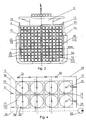
Figure 1 is a main view of the vessel; -
Figure 2 is a plan view of the vessel; -
Figure 3 is the cross-section of the vessel according to its middle section; -
Figure 4 is an end view of the stacked containers with tanks and a shipboard compressed gas loading system; -
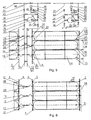
Figure 5 is a view of the board at the stacked containers with tanks and a scheme of shipboard compressed gas loading system; -
Figure 6 is a top view of the stacked containers with tanks and a shipboard compressed gas loading system. - The vessel for transporting compressed gas comprises of a hull of the
vessel 1, divided into double-jointedcells 2 with vertical cell guides 3, longitudinal 4 andtransverse bulkheads 5 and also containers partitions arranged between the tiers inside thecells 2, of double-jointed type, not closed, of truss type structure or closed ones which are impermeable to water andgas 6, the distance between them is 1.8 meters. Double transverse bulkheads which are impermeable to water andgas 7 with intermediate size of 0.8 meters are separatingforage compartments 2 from theengine room 8 and the lower tiers of thedeckhouse 9 and double-jointed transverse bulkheads which are impermeable to water andgas 10 are arranged between thecompartment 11 andcells 2, which are the closest to the shipboard bow. - Compressed
gas distribution manifolds 12 of compressed gas overload shipboard system are located between double-jointedbulkheads 6. - Each double-
jointed cell 2 is closed by one jointedhatch cover 13 and is separated from other cells bybulkheads -
Containers 15 are installed in vertical cell guides 3 and connected between each other with quick-turningcontainer stoppers 14, wherecylindrical tanks 16 made of composite materials with spherical end parts are arranged horizontally.Containers 15 are located in three vertical cell guides 3 of their cell with the ends towardscontainers 15 of the other part of the double-jointed cell 2, and acommon manifold 12 is placed between them at thebulkhead 6. Theconnection pipes 17 are arranged on each tank on the ends providing the described arrangement of the containers, aset cap 18 is located on one of them and a shut-offvalve 19 is connected to another. - The
safety valve 20, thepressure sensor 21, thetemperature sensor 22 and thecondensate detection sensor 23 are also placed ontanks 16 andcondensate pipe connections 24 are mounted in the bottom oftanks 16, where shut-offvalves 25 are located. - In this particular example, according to the external dimensions and mounting elements,
containers 15 are standard shipboard 40 feet containers having external dimensions as follows: length of 12 192 mm, width of 2438 mm and height of 2591 mm. Such containers are suitable for further transportation by shallow-draft vessels on the rivers as well as by road and railway transport, but one may use other standard containers of new sizes. -
Tanks 16 ofcontainers 15 are connected through their shut-offvalve 19 by theflexible pipeline 26 with the manifold 12, which consists of vertically orientedpipes 27 with shut-offvalves 28.Pipes 27 are interconnected by a lockingpipeline 29 with shut-offvalves 30. The manifold, which is placed between the tiers in the cells, allows reducing the length of pipes and simplifying maintenance and management of gas loading system. Themanifold system 12 also includes thepipeline 31, which is connected through the shut-offvalve 32 tomanifold pipes 12 and through the shut-offvalve 33 to the compressor and, as a result, through the connectingdevice 44 to external storage facilities. -
Manifold pipes 12 are connected through shut-offvalves connection unit 44 and to the pipeline of external gas storage. The shut-offvalve 45 and thegas meter 46 are also installed. And the manifold pipe system of each cells pair 2 is connected to the connectingpipeline 47 laid on the upper deck with shut-offvalves 48. - Each double-
jointed cell 2, mentioned in the describedmanifold system 12, has thecompressor 49, which is connected to thepipe 31 through the shut-offvalve 36 and thepipe 27 through the shut-offvalve 35 and thesafety valve 50. - The
compressor 49 is bypassed by the pipeline with shut-offvalves valves - The
connection unit 44 and thecompressor 49 are installed in the hermetic stowed position and in the intensively ventilatedarea 51, which is established at the level of the upper deck in the area of the manifolds 12 location, in each double-jointed cell 2 along the length of the ship. -
Cells 11 are not connected to the general compressed gas loading system and are used for other gases that are by-products, such as helium, while the main gas for transportation is methane. - Although, with the existing scheme, it is possible to close and block the access to specified manifolds of the selected double-jointed
cells 2 and to transport several different gases by one ship. - Each double-
jointed cell 2 has twocontainers 52 with the empty dump tank 53, with the ability to drain condensate or gas excess in thecargo tanks 16 into it, providing that dump tanks 53 are connected through theirsafety valves 54 and pipelines are brought out to the upper deck to thegas combustion device 55. - The condensate collector and drain system includes shut-off
valves 25, mounted in the lower part ofcontainers 16, which are connected throughflexible pipelines 56 and shut-offvalves 57 withvertical pipes 58, interconnected byswitchers 59 with each other and connected to theseparate pump 60. - The hatch cover availability makes possible to use the vessel according to the invention, both in gas uploading and offloading mode through the gas loading shipboard system or to load it with containers filled with gas tanks or offload filled containers at the container terminal and deliver gas by other means of transport.
- If it is intended to offload containers only during vessel repair, then instead of hatch covers, deckhead cladding panels can be provided at the
deckhouse 61 that are installed at the coaming, welded and contain constructive elements that can be cut in case of repair and access to some cell. - Considering the fact that the gas temperature is changing during gas uploading and offloading, some shut-off valves and
manifold outlet pipelines 12 are covered with heat-carrying medium. The system is not shown herein, as it is known to the experts and is not the subject of the invention. - Rotatable container locks allow loading spreader at the container terminal to install automatically or unload containers from the ship. Fixing
container 15 by centering cones and ties are more suitable for gas uploading and offloading through the shipboard system. - Gas uploading and offloading is produced both by gravity and by compressor gas supply according to the differential pressure.
- Receiving
devices 44 are connected to the gas storage outer pipeline at the production field, and asempty tanks 16 are under residual pressure of 1 kg/cm2 gas is taken from the external gas storage under pressure above 100 kg/cm2 through the open shut-offvalves manifolds 12 of eachcell 2, and gas enters frommanifolds 12 through the open shut-offvalves tanks 16 ofcontainers 15. In this case shut-offvalves valves jointed cell 2, in which the shut-offvalve 38 is closed and gas enters thetank 16 through the shut-offvalve 42 and other ones above mentioned for the first cell (seeFig. 5 , which shows a part of the loading system of another double-jointed cell 2). - When gas drop is reducing, shut-off
valves unit 44, and shut-offvalves compressor 49 and continues to flow until reaching the specified pressure intanks 16. When tanks of this double-jointed cell are filled, thecompressor 49 is off, shut-offvalves valves Figure 5 ), then the shut-offvalve 48 is opening. Into the next double-jointed cell, which is not connected directly through theunit 44 to the external gas storage, gas is received with open shut-offvalves compressor 49 of this cell and shut-offvalves manifold valves 12 are similar to theFigure .5 . - The junction points with the pipes of the manifold 12 are denoted with letters A and B.
- During gas pumping, if it is necessary, the shut-off
valve 45 is opening andgas counter 46 starts to work, but pressure control enables to estimate gas quantity without the counter. - In case of overpressure above in the
compressor 49 thesafety valve 50 is activated. - During transportation, in case of exceeding the maximum of allowable pressure in any of the
tanks 16, gas is discharged into dump tanks 53. In this case the shut-offvalve 19 of emergency tank is opening, the shut-offvalve 28 at themanifold 12 of corresponding tanks is opening and a part of gas flows into the drain tank 53 by gravity. The safety valve of the dump tanks is set to the pressure which is 50 kg/cm2 less than the set pressure ofcargo tanks 16. When pressure exceeds the values at the dump tank, gas is discharged from the dump tanks 53 into the gas combustion device and they are always ready, with pressure drop of 50 kg/cm2, to take gas from thecargo tanks 16 with high pressure above normal. - Also, the system allows redistributing gas between tanks in case of incomplete vessel loading and tanks being in emergency state in any of the cells.
- Condensate can be removed from the tanks by using the gas pressure in tanks both before gas uploading and on the beginning of uploading or by the
additional pump 60. - Manifold pipes purging by inert gases is performed when shut-off
valves 32 are opened. - The schemes show shut-off valves in order to explain the vessel's design and schemes of the loading, control and storage system for transportation of compressed gas, without specifying the type and the drive, but the latter is a well known electrical, hydraulic and pneumatic remote control of all types of valves in engineering, which is not described in the claim, as it is not the subject of invention. Specialists and engineers of automation control are able to develop remote control systems of shut-off valves and compressors using programmable controllers connected to sensors of pressure, temperature and by switching on the operation modes for specified programs.
Claims (12)
- A vessel for transporting compressed gas, comprising cargo holds with tanks for storing gas during transportation arranged in said cargo holds equipped with pipelines, signaling sensors, a shutoff fitting and a connecting fitting, and compressors, characterized in that the hull of the vessel is divided into cells (2) with vertical guides (3), at least one bulkhead (4, 5) in said cells is impermeable to water and gas, and unified containers (15) with the tanks (16) for compressed gas arranged horizontally therein are mounted one on top of the other in the guides (3), said containers (15) being connected to a vessel system for compressed gas transfer, wherein the hull of the vessel is divided into the cells (2) in such a way that, in the zone of at least one bulkhead delimiting the cell, a distance of from 0.8 to 2 metres is ensured, and collectors (12) for distributing the compressed gas, the pipelines (17) with the shutoff valves (19), the compressor (49) and accident monitoring and control equipment are arranged in this space.
- The vessel according to claim 1, wherein each double-jointed cells (2) its closed by one jointed hatch cover (13) which is impermeable to water and gas and is separated from other double cells by bulkheads (4, 5) which are impermeable to water and gas.
- The vessel according to claim 2, wherein at least one container (52) with empty dump tank (53) is placed in each double-jointed cell (2), with the ability to drain condensate or gas excess in the cargo containers (15) into it, providing that dump tanks (53) are connected through the safety valves and pipelines are brought out to the upper deck to the excess gas burner.
- A vessel according to claim 2, wherein said each tank (16) is connected through a shut-off valve (19) with manifold (12) with a flexible pipeline (26) or a expansion bellows, and the manifold (12) is arranged between the ends of containers of the parts of double-jointed cells (2) and connected by the pipeline (31) through a shut-off valve (32) and safety equipment with the compressor (49) providing that the pipeline is brought out into the upper deck from each double-jointed cells manifold and has the connecting fittings adjustable to external gas storage and pipeline fittings connected to another double-jointed cell (2).
- A vessel according to claim 2, wherein the said compressor connection system provides the bypass by the pipeline with shut-off valves (38, 37, 34, 39, 40, 49) enabling to transmit gas under pressure by gravity.
- A vessel according to claim 1, wherein the said containers (15) are connected between each other by traversing container locks or centering cones and ties.
- A vessel according to claim 1, wherein said cylindrical tanks (16) made of composite materials are placed in the containers (15) in horizontal position, each one having at least one connection pipe (17), shut-off (25) and safety valves (20), pressure and temperature sensors (21, 22), as well as a condensate detection sensory (23) and a condensate drain pipe connections (24).
- A vessel according to claim 7, wherein said outlet connection pipe is arranged on both ends of each tank (16).
- A vessel according to claim 1, wherein said containers (15) are standard 40 feet shipboard containers with external dimensions: length of 12 192 mm, width of 2438 mm and height of 2591 mm.
- A vessel according to claim 1, wherein said that in each individual cell (2) or group of cells (2) is closed on top by hatch cover which is impermeable to water.
- A vessel according to claim 1, wherein said that in each individual cell (2) or group of cells (2) is closed on top by a removable deckhead cladding.
- A vessel according to claim 1, wherein said that the connection pipes, shut-off valves and outlet pipelines from the manifolds (12) to the connecting fitting are covered with coolant jackets.
Applications Claiming Priority (2)
| Application Number | Priority Date | Filing Date | Title |
|---|---|---|---|
| UAA201203198A UA101584C2 (en) | 2012-03-19 | 2012-03-19 | Vessel for transportation of compressed gas |
| PCT/UA2012/000112 WO2013141828A1 (en) | 2012-03-19 | 2012-12-14 | Vessel for transporting compressed gas |
Publications (3)
| Publication Number | Publication Date |
|---|---|
| EP2829467A1 EP2829467A1 (en) | 2015-01-28 |
| EP2829467A4 EP2829467A4 (en) | 2016-01-13 |
| EP2829467B1 true EP2829467B1 (en) | 2016-06-22 |
Family
ID=56404841
Family Applications (1)
| Application Number | Title | Priority Date | Filing Date |
|---|---|---|---|
| EP12872093.5A Active EP2829467B1 (en) | 2012-03-19 | 2012-12-14 | Vessel for transporting compressed gas |
Country Status (5)
| Country | Link |
|---|---|
| EP (1) | EP2829467B1 (en) |
| CN (1) | CN104379440B (en) |
| RU (1) | RU2589811C2 (en) |
| UA (1) | UA101584C2 (en) |
| WO (1) | WO2013141828A1 (en) |
Families Citing this family (10)
| Publication number | Priority date | Publication date | Assignee | Title |
|---|---|---|---|---|
| CN105953068B (en) * | 2016-05-20 | 2019-04-09 | 蓬莱中柏京鲁船业有限公司 | A kind of vessel for transport of compressed natural gas and its method of modifying |
| CN109398602B (en) * | 2017-08-15 | 2021-09-10 | 上海船厂船舶有限公司 | Method for installing high-pressure air bottle assembly for drilling ship |
| CN110642217A (en) * | 2019-07-01 | 2020-01-03 | Amg能源新加坡私人有限公司 | System and method for LNG transport and distribution |
| CN110878909B (en) * | 2019-11-25 | 2024-02-20 | 江苏国富氢能技术装备股份有限公司 | High-pressure hydrogen cylinder group packaging structure |
| JP7499147B2 (en) * | 2020-10-27 | 2024-06-13 | 住友重機械マリンエンジニアリング株式会社 | Ships |
| WO2022120500A1 (en) * | 2020-12-11 | 2022-06-16 | Global Hydrogen Ventures Pty Ltd | Apparatus for gas storage and transport |
| GB2613374B (en) | 2021-12-01 | 2024-06-26 | Subsea 7 Norway As | Subsea hydrogen storage system |
| CN114493323A (en) * | 2022-02-11 | 2022-05-13 | 内蒙古中科装备有限公司 | Method, system and medium for emergency purging of hydrogen storage vessels |
| CN115303420B (en) * | 2022-09-14 | 2025-06-27 | 上海外高桥造船有限公司 | System and method for preventing liquid accumulation at the bottom of cryogenic liquid tank, and ship |
| CN119957806A (en) * | 2025-01-27 | 2025-05-09 | 中国科学院上海高等研究院 | Gas storage device |
Family Cites Families (10)
| Publication number | Priority date | Publication date | Assignee | Title |
|---|---|---|---|---|
| FR2135575B1 (en) * | 1971-05-05 | 1973-07-13 | Liquid Gas Anlagen Union | |
| DE2253023C3 (en) * | 1972-10-28 | 1979-06-07 | Liquid Gas International Gmbh, 5480 Remagen | Battery tank for pressureless or pressurized liquids, primarily liquefied gases, especially for the transport of liquefied gas on ships |
| DE2337673A1 (en) * | 1973-07-25 | 1975-02-06 | Dieter Fischer | Floating natural gas transporter - with pipeline section bundles and dummy bows and sterns |
| US5839383A (en) * | 1995-10-30 | 1998-11-24 | Enron Lng Development Corp. | Ship based gas transport system |
| IL123547A0 (en) | 1995-10-30 | 1998-10-30 | Enron Lng Dev Corp | Ship based system for compressed natural gas transport |
| DZ2528A1 (en) * | 1997-06-20 | 2003-02-01 | Exxon Production Research Co | Container for the storage of pressurized liquefied natural gas and a process for the transport of pressurized liquefied natural gas and natural gas treatment system to produce liquefied natural gas under pressure. |
| RU2300480C1 (en) | 2005-09-22 | 2007-06-10 | Общество с ограниченной ответственностью "Инжиниринг, технический анализ, разработки и исследования" | Ship for transportation of compressed gas (versions) |
| RU2299151C1 (en) | 2005-09-22 | 2007-05-20 | Общество с ограниченной ответственностью "Инжиниринг, технический анализ, разработки и исследования" | Ship for carrying compressed gas |
| CN201395358Y (en) * | 2009-04-10 | 2010-02-03 | 荆门宏图特种飞行器制造有限公司 | Compressed natural gas container |
| CN201462388U (en) * | 2009-05-28 | 2010-05-12 | 荆门宏图特种飞行器制造有限公司 | Oilfield associated gas or compressed natural gas tank container |
-
2012
- 2012-03-19 UA UAA201203198A patent/UA101584C2/en unknown
- 2012-12-14 CN CN201280073271.9A patent/CN104379440B/en not_active Expired - Fee Related
- 2012-12-14 RU RU2014141807/11A patent/RU2589811C2/en not_active IP Right Cessation
- 2012-12-14 EP EP12872093.5A patent/EP2829467B1/en active Active
- 2012-12-14 WO PCT/UA2012/000112 patent/WO2013141828A1/en not_active Ceased
Also Published As
| Publication number | Publication date |
|---|---|
| RU2589811C2 (en) | 2016-07-10 |
| RU2014141807A (en) | 2016-05-10 |
| EP2829467A1 (en) | 2015-01-28 |
| CN104379440B (en) | 2017-02-22 |
| WO2013141828A1 (en) | 2013-09-26 |
| CN104379440A (en) | 2015-02-25 |
| EP2829467A4 (en) | 2016-01-13 |
| UA101584C2 (en) | 2013-04-10 |
Similar Documents
| Publication | Publication Date | Title |
|---|---|---|
| EP2829467B1 (en) | Vessel for transporting compressed gas | |
| KR100458142B1 (en) | Compressed Natural Gas Transportation Ship Foundation System | |
| EP0946387B1 (en) | Ship based gas transport system | |
| EP1322518B1 (en) | Methods and apparatus for compressed gas | |
| ES2952648T3 (en) | System and method for loading, storage and unloading of natural gas from ships | |
| MXPA97002712A (en) | System based on boat for transport of natural gas comprim | |
| WO2010103260A1 (en) | Vessel for transport of liquefied natural gas or liquefied co2 | |
| KR20140111668A (en) | System for containing and transporting compressed natural gas in inspectable cylindrical containers, combined in modules | |
| WO2014086413A1 (en) | Integrated and improved system for sea transportation of compressed natural gas in vessels, including multiple treatment steps for lowering the temperature of the combined cooling and chilling type | |
| AU6658000A (en) | Natural gas composition transport system and method | |
| HK1182065A1 (en) | Buoyant body, in particular container ship | |
| SK50562016U1 (en) | Complex shipping and store system of LNG supply in the river transporting logistics chain | |
| HK1182065B (en) | Buoyant body, in particular container ship | |
| HK1022879B (en) | Ship based gas transport system | |
| SK50232016A3 (en) | Complex shipping and store system of LNG supply in the river transporting logistics chain |
Legal Events
| Date | Code | Title | Description |
|---|---|---|---|
| PUAI | Public reference made under article 153(3) epc to a published international application that has entered the european phase |
Free format text: ORIGINAL CODE: 0009012 |
|
| 17P | Request for examination filed |
Effective date: 20141013 |
|
| AK | Designated contracting states |
Kind code of ref document: A1 Designated state(s): AL AT BE BG CH CY CZ DE DK EE ES FI FR GB GR HR HU IE IS IT LI LT LU LV MC MK MT NL NO PL PT RO RS SE SI SK SM TR |
|
| AX | Request for extension of the european patent |
Extension state: BA ME |
|
| DAX | Request for extension of the european patent (deleted) | ||
| RA4 | Supplementary search report drawn up and despatched (corrected) |
Effective date: 20151216 |
|
| RIC1 | Information provided on ipc code assigned before grant |
Ipc: B63B 27/25 20060101ALI20151210BHEP Ipc: B63B 25/14 20060101AFI20151210BHEP Ipc: B63B 25/08 20060101ALI20151210BHEP Ipc: B63B 17/00 20060101ALI20151210BHEP Ipc: B67D 9/00 20100101ALI20151210BHEP Ipc: F17C 1/00 20060101ALI20151210BHEP Ipc: B63B 3/56 20060101ALI20151210BHEP Ipc: F17C 13/08 20060101ALI20151210BHEP Ipc: B63B 11/02 20060101ALI20151210BHEP |
|
| GRAP | Despatch of communication of intention to grant a patent |
Free format text: ORIGINAL CODE: EPIDOSNIGR1 |
|
| GRAS | Grant fee paid |
Free format text: ORIGINAL CODE: EPIDOSNIGR3 |
|
| INTG | Intention to grant announced |
Effective date: 20160418 |
|
| GRAA | (expected) grant |
Free format text: ORIGINAL CODE: 0009210 |
|
| AK | Designated contracting states |
Kind code of ref document: B1 Designated state(s): AL AT BE BG CH CY CZ DE DK EE ES FI FR GB GR HR HU IE IS IT LI LT LU LV MC MK MT NL NO PL PT RO RS SE SI SK SM TR |
|
| REG | Reference to a national code |
Ref country code: GB Ref legal event code: FG4D |
|
| REG | Reference to a national code |
Ref country code: CH Ref legal event code: EP |
|
| REG | Reference to a national code |
Ref country code: IE Ref legal event code: FG4D |
|
| REG | Reference to a national code |
Ref country code: AT Ref legal event code: REF Ref document number: 807494 Country of ref document: AT Kind code of ref document: T Effective date: 20160715 |
|
| REG | Reference to a national code |
Ref country code: DE Ref legal event code: R096 Ref document number: 602012019867 Country of ref document: DE |
|
| REG | Reference to a national code |
Ref country code: LT Ref legal event code: MG4D |
|
| REG | Reference to a national code |
Ref country code: NL Ref legal event code: MP Effective date: 20160622 |
|
| PG25 | Lapsed in a contracting state [announced via postgrant information from national office to epo] |
Ref country code: NO Free format text: LAPSE BECAUSE OF FAILURE TO SUBMIT A TRANSLATION OF THE DESCRIPTION OR TO PAY THE FEE WITHIN THE PRESCRIBED TIME-LIMIT Effective date: 20160922 Ref country code: LT Free format text: LAPSE BECAUSE OF FAILURE TO SUBMIT A TRANSLATION OF THE DESCRIPTION OR TO PAY THE FEE WITHIN THE PRESCRIBED TIME-LIMIT Effective date: 20160622 Ref country code: FI Free format text: LAPSE BECAUSE OF FAILURE TO SUBMIT A TRANSLATION OF THE DESCRIPTION OR TO PAY THE FEE WITHIN THE PRESCRIBED TIME-LIMIT Effective date: 20160622 |
|
| PG25 | Lapsed in a contracting state [announced via postgrant information from national office to epo] |
Ref country code: GR Free format text: LAPSE BECAUSE OF FAILURE TO SUBMIT A TRANSLATION OF THE DESCRIPTION OR TO PAY THE FEE WITHIN THE PRESCRIBED TIME-LIMIT Effective date: 20160923 Ref country code: RS Free format text: LAPSE BECAUSE OF FAILURE TO SUBMIT A TRANSLATION OF THE DESCRIPTION OR TO PAY THE FEE WITHIN THE PRESCRIBED TIME-LIMIT Effective date: 20160622 Ref country code: HR Free format text: LAPSE BECAUSE OF FAILURE TO SUBMIT A TRANSLATION OF THE DESCRIPTION OR TO PAY THE FEE WITHIN THE PRESCRIBED TIME-LIMIT Effective date: 20160622 Ref country code: SE Free format text: LAPSE BECAUSE OF FAILURE TO SUBMIT A TRANSLATION OF THE DESCRIPTION OR TO PAY THE FEE WITHIN THE PRESCRIBED TIME-LIMIT Effective date: 20160622 Ref country code: LV Free format text: LAPSE BECAUSE OF FAILURE TO SUBMIT A TRANSLATION OF THE DESCRIPTION OR TO PAY THE FEE WITHIN THE PRESCRIBED TIME-LIMIT Effective date: 20160622 Ref country code: NL Free format text: LAPSE BECAUSE OF FAILURE TO SUBMIT A TRANSLATION OF THE DESCRIPTION OR TO PAY THE FEE WITHIN THE PRESCRIBED TIME-LIMIT Effective date: 20160622 |
|
| REG | Reference to a national code |
Ref country code: FR Ref legal event code: PLFP Year of fee payment: 5 |
|
| PG25 | Lapsed in a contracting state [announced via postgrant information from national office to epo] |
Ref country code: SK Free format text: LAPSE BECAUSE OF FAILURE TO SUBMIT A TRANSLATION OF THE DESCRIPTION OR TO PAY THE FEE WITHIN THE PRESCRIBED TIME-LIMIT Effective date: 20160622 Ref country code: RO Free format text: LAPSE BECAUSE OF FAILURE TO SUBMIT A TRANSLATION OF THE DESCRIPTION OR TO PAY THE FEE WITHIN THE PRESCRIBED TIME-LIMIT Effective date: 20160622 Ref country code: IS Free format text: LAPSE BECAUSE OF FAILURE TO SUBMIT A TRANSLATION OF THE DESCRIPTION OR TO PAY THE FEE WITHIN THE PRESCRIBED TIME-LIMIT Effective date: 20161022 Ref country code: EE Free format text: LAPSE BECAUSE OF FAILURE TO SUBMIT A TRANSLATION OF THE DESCRIPTION OR TO PAY THE FEE WITHIN THE PRESCRIBED TIME-LIMIT Effective date: 20160622 Ref country code: CZ Free format text: LAPSE BECAUSE OF FAILURE TO SUBMIT A TRANSLATION OF THE DESCRIPTION OR TO PAY THE FEE WITHIN THE PRESCRIBED TIME-LIMIT Effective date: 20160622 |
|
| PG25 | Lapsed in a contracting state [announced via postgrant information from national office to epo] |
Ref country code: ES Free format text: LAPSE BECAUSE OF FAILURE TO SUBMIT A TRANSLATION OF THE DESCRIPTION OR TO PAY THE FEE WITHIN THE PRESCRIBED TIME-LIMIT Effective date: 20160622 Ref country code: PL Free format text: LAPSE BECAUSE OF FAILURE TO SUBMIT A TRANSLATION OF THE DESCRIPTION OR TO PAY THE FEE WITHIN THE PRESCRIBED TIME-LIMIT Effective date: 20160622 Ref country code: PT Free format text: LAPSE BECAUSE OF FAILURE TO SUBMIT A TRANSLATION OF THE DESCRIPTION OR TO PAY THE FEE WITHIN THE PRESCRIBED TIME-LIMIT Effective date: 20161024 Ref country code: BE Free format text: LAPSE BECAUSE OF FAILURE TO SUBMIT A TRANSLATION OF THE DESCRIPTION OR TO PAY THE FEE WITHIN THE PRESCRIBED TIME-LIMIT Effective date: 20160622 Ref country code: SM Free format text: LAPSE BECAUSE OF FAILURE TO SUBMIT A TRANSLATION OF THE DESCRIPTION OR TO PAY THE FEE WITHIN THE PRESCRIBED TIME-LIMIT Effective date: 20160622 |
|
| REG | Reference to a national code |
Ref country code: DE Ref legal event code: R097 Ref document number: 602012019867 Country of ref document: DE |
|
| PLBE | No opposition filed within time limit |
Free format text: ORIGINAL CODE: 0009261 |
|
| STAA | Information on the status of an ep patent application or granted ep patent |
Free format text: STATUS: NO OPPOSITION FILED WITHIN TIME LIMIT |
|
| 26N | No opposition filed |
Effective date: 20170323 |
|
| PG25 | Lapsed in a contracting state [announced via postgrant information from national office to epo] |
Ref country code: DK Free format text: LAPSE BECAUSE OF FAILURE TO SUBMIT A TRANSLATION OF THE DESCRIPTION OR TO PAY THE FEE WITHIN THE PRESCRIBED TIME-LIMIT Effective date: 20160622 |
|
| PG25 | Lapsed in a contracting state [announced via postgrant information from national office to epo] |
Ref country code: SI Free format text: LAPSE BECAUSE OF FAILURE TO SUBMIT A TRANSLATION OF THE DESCRIPTION OR TO PAY THE FEE WITHIN THE PRESCRIBED TIME-LIMIT Effective date: 20160622 |
|
| REG | Reference to a national code |
Ref country code: FR Ref legal event code: PLFP Year of fee payment: 6 |
|
| PG25 | Lapsed in a contracting state [announced via postgrant information from national office to epo] |
Ref country code: HU Free format text: LAPSE BECAUSE OF FAILURE TO SUBMIT A TRANSLATION OF THE DESCRIPTION OR TO PAY THE FEE WITHIN THE PRESCRIBED TIME-LIMIT; INVALID AB INITIO Effective date: 20121214 |
|
| PG25 | Lapsed in a contracting state [announced via postgrant information from national office to epo] |
Ref country code: MK Free format text: LAPSE BECAUSE OF FAILURE TO SUBMIT A TRANSLATION OF THE DESCRIPTION OR TO PAY THE FEE WITHIN THE PRESCRIBED TIME-LIMIT Effective date: 20160622 Ref country code: CY Free format text: LAPSE BECAUSE OF FAILURE TO SUBMIT A TRANSLATION OF THE DESCRIPTION OR TO PAY THE FEE WITHIN THE PRESCRIBED TIME-LIMIT Effective date: 20160622 |
|
| PG25 | Lapsed in a contracting state [announced via postgrant information from national office to epo] |
Ref country code: BG Free format text: LAPSE BECAUSE OF FAILURE TO SUBMIT A TRANSLATION OF THE DESCRIPTION OR TO PAY THE FEE WITHIN THE PRESCRIBED TIME-LIMIT Effective date: 20160622 |
|
| PG25 | Lapsed in a contracting state [announced via postgrant information from national office to epo] |
Ref country code: MT Free format text: LAPSE BECAUSE OF NON-PAYMENT OF DUE FEES Effective date: 20161214 |
|
| PG25 | Lapsed in a contracting state [announced via postgrant information from national office to epo] |
Ref country code: AL Free format text: LAPSE BECAUSE OF FAILURE TO SUBMIT A TRANSLATION OF THE DESCRIPTION OR TO PAY THE FEE WITHIN THE PRESCRIBED TIME-LIMIT Effective date: 20160622 |
|
| REG | Reference to a national code |
Ref country code: AT Ref legal event code: UEP Ref document number: 807494 Country of ref document: AT Kind code of ref document: T Effective date: 20160622 |
|
| PGFP | Annual fee paid to national office [announced via postgrant information from national office to epo] |
Ref country code: LU Payment date: 20181121 Year of fee payment: 7 |
|
| PGFP | Annual fee paid to national office [announced via postgrant information from national office to epo] |
Ref country code: DE Payment date: 20181121 Year of fee payment: 7 Ref country code: MC Payment date: 20181122 Year of fee payment: 7 |
|
| PGFP | Annual fee paid to national office [announced via postgrant information from national office to epo] |
Ref country code: IE Payment date: 20190520 Year of fee payment: 11 Ref country code: FR Payment date: 20181120 Year of fee payment: 7 Ref country code: GB Payment date: 20181121 Year of fee payment: 7 |
|
| REG | Reference to a national code |
Ref country code: DE Ref legal event code: R119 Ref document number: 602012019867 Country of ref document: DE |
|
| PG25 | Lapsed in a contracting state [announced via postgrant information from national office to epo] |
Ref country code: MC Free format text: LAPSE BECAUSE OF NON-PAYMENT OF DUE FEES Effective date: 20200102 |
|
| GBPC | Gb: european patent ceased through non-payment of renewal fee |
Effective date: 20191214 |
|
| PG25 | Lapsed in a contracting state [announced via postgrant information from national office to epo] |
Ref country code: IE Free format text: LAPSE BECAUSE OF NON-PAYMENT OF DUE FEES Effective date: 20191214 Ref country code: IT Free format text: LAPSE BECAUSE OF NON-PAYMENT OF DUE FEES Effective date: 20191214 Ref country code: DE Free format text: LAPSE BECAUSE OF NON-PAYMENT OF DUE FEES Effective date: 20200701 Ref country code: FR Free format text: LAPSE BECAUSE OF NON-PAYMENT OF DUE FEES Effective date: 20191231 Ref country code: GB Free format text: LAPSE BECAUSE OF NON-PAYMENT OF DUE FEES Effective date: 20191214 Ref country code: LU Free format text: LAPSE BECAUSE OF NON-PAYMENT OF DUE FEES Effective date: 20191214 |
|
| PGFP | Annual fee paid to national office [announced via postgrant information from national office to epo] |
Ref country code: CH Payment date: 20201217 Year of fee payment: 9 |
|
| REG | Reference to a national code |
Ref country code: CH Ref legal event code: PL |
|
| PGFP | Annual fee paid to national office [announced via postgrant information from national office to epo] |
Ref country code: AT Payment date: 20220701 Year of fee payment: 10 |
|
| PG25 | Lapsed in a contracting state [announced via postgrant information from national office to epo] |
Ref country code: LI Free format text: LAPSE BECAUSE OF NON-PAYMENT OF DUE FEES Effective date: 20211231 Ref country code: CH Free format text: LAPSE BECAUSE OF NON-PAYMENT OF DUE FEES Effective date: 20211231 |
|
| PGFP | Annual fee paid to national office [announced via postgrant information from national office to epo] |
Ref country code: TR Payment date: 20221212 Year of fee payment: 11 |
|
| REG | Reference to a national code |
Ref country code: AT Ref legal event code: MM01 Ref document number: 807494 Country of ref document: AT Kind code of ref document: T Effective date: 20221214 |
|
| PG25 | Lapsed in a contracting state [announced via postgrant information from national office to epo] |
Ref country code: AT Free format text: LAPSE BECAUSE OF NON-PAYMENT OF DUE FEES Effective date: 20221214 |