EP2829401A2 - Procédé de compensation d'une dilatation transversale consécutive à l'allongement en éventail d'une bande de matériau imprimée à l'aide de plusieurs couleurs d'impression dans une imprimante - Google Patents
Procédé de compensation d'une dilatation transversale consécutive à l'allongement en éventail d'une bande de matériau imprimée à l'aide de plusieurs couleurs d'impression dans une imprimante Download PDFInfo
- Publication number
- EP2829401A2 EP2829401A2 EP14166158.7A EP14166158A EP2829401A2 EP 2829401 A2 EP2829401 A2 EP 2829401A2 EP 14166158 A EP14166158 A EP 14166158A EP 2829401 A2 EP2829401 A2 EP 2829401A2
- Authority
- EP
- European Patent Office
- Prior art keywords
- printing
- cylinder
- fan
- value
- web
- Prior art date
- Legal status (The legal status is an assumption and is not a legal conclusion. Google has not performed a legal analysis and makes no representation as to the accuracy of the status listed.)
- Granted
Links
Images


Classifications
-
- B—PERFORMING OPERATIONS; TRANSPORTING
- B41—PRINTING; LINING MACHINES; TYPEWRITERS; STAMPS
- B41F—PRINTING MACHINES OR PRESSES
- B41F13/00—Common details of rotary presses or machines
- B41F13/08—Cylinders
- B41F13/10—Forme cylinders
- B41F13/12—Registering devices
- B41F13/14—Registering devices with means for displacing the cylinders
-
- B—PERFORMING OPERATIONS; TRANSPORTING
- B41—PRINTING; LINING MACHINES; TYPEWRITERS; STAMPS
- B41F—PRINTING MACHINES OR PRESSES
- B41F33/00—Indicating, counting, warning, control or safety devices
- B41F33/0009—Central control units
-
- B—PERFORMING OPERATIONS; TRANSPORTING
- B41—PRINTING; LINING MACHINES; TYPEWRITERS; STAMPS
- B41F—PRINTING MACHINES OR PRESSES
- B41F7/00—Rotary lithographic machines
- B41F7/02—Rotary lithographic machines for offset printing
- B41F7/12—Rotary lithographic machines for offset printing using two cylinders one of which serves two functions, e.g. as a transfer and impression cylinder in perfecting machines
-
- B—PERFORMING OPERATIONS; TRANSPORTING
- B41—PRINTING; LINING MACHINES; TYPEWRITERS; STAMPS
- B41P—INDEXING SCHEME RELATING TO PRINTING, LINING MACHINES, TYPEWRITERS, AND TO STAMPS
- B41P2213/00—Arrangements for actuating or driving printing presses; Auxiliary devices or processes
- B41P2213/90—Register control
-
- B—PERFORMING OPERATIONS; TRANSPORTING
- B41—PRINTING; LINING MACHINES; TYPEWRITERS; STAMPS
- B41P—INDEXING SCHEME RELATING TO PRINTING, LINING MACHINES, TYPEWRITERS, AND TO STAMPS
- B41P2233/00—Arrangements for the operation of printing presses
- B41P2233/50—Marks on printed material
- B41P2233/51—Marks on printed material for colour quality control
-
- B—PERFORMING OPERATIONS; TRANSPORTING
- B41—PRINTING; LINING MACHINES; TYPEWRITERS; STAMPS
- B41P—INDEXING SCHEME RELATING TO PRINTING, LINING MACHINES, TYPEWRITERS, AND TO STAMPS
- B41P2233/00—Arrangements for the operation of printing presses
- B41P2233/50—Marks on printed material
- B41P2233/52—Marks on printed material for registering
Definitions
- the invention relates to a method for compensating a fan-out-related transverse strain of a printing substrate printed in a printing machine with a plurality of printing inks.
- DE 10 2004 004 264 A1 are a method for compensating for a transverse strain and / or a longitudinal expansion of a printing material and a Printing machine with a plurality of at least one print image on a printing material-producing printing units known, wherein a portion of the transverse strain of the printing material is compensated except by measures in the imaging by an axial displacement of a forme cylinder relative to a reference mark of the printing material and wherein a further part of the transverse strain of the printing material by the use of an image controller is counteracted.
- the compensation of the transverse strain in the imaging can take account of the fact that the transverse strain has a stronger effect on the "outer" printed image areas which are close to the face with respect to the forme cylinder than on the "inner” printed image areas arranged close to the center of the forme cylinder.
- a side register correction apparatus comprising a register correction unit capable of correcting register movement of a fiber web through each plural printing units, and a fan correction unit capable of correcting a width of the fiber web stretched in a width direction;
- Page register correcting apparatus comprising: a) a register detecting and estimating unit capable of estimating and detecting a register correction amount by the register correcting unit based on at least two register marks printed on the fibrous web by each of the printing units when plural printing units are in one moving direction Print fiber web for performing correction by the register correction unit and the fan correction unit; b) a register correction control unit capable of automatically controlling the register correction unit in real time based on the register correction amount provided by the register detecting and estimating unit is derived; c) a fan detection and estimation unit capable of estimating and detecting a fan correction amount by the fan correction unit based on a register flag; and d) a fan correction control unit capable of automatically controlling the fan correction unit in real time based on the fan correction amount
- a device for correcting the fan-out effect on web-fed rotary printing presses with a train locally out of its plane deflecting actuator wherein the actuator is actuated by a control loop which includes a control device on the input side with a transmitter for the deflection of the web in Direction of its width and the output side is in communication with an actuating device of the actuating element, wherein preferably a read on the web registered register marks reading head is connected to the control device, wherein the read head and the control device of the type a color register control unit for circumferential and side registers are embodied, wherein the control device is connected to both the actuator of the control element for the fan-out correction and to an adjustment device for the circumferential register.
- a method for influencing the fan-out effect by means of a device for influencing the fan-out effect wherein a sensor of a 9.register supposedung / -regelung, parts of a 9.register supposedung / -regelung and / or measured values of a page register control / regulation for driving a device for influencing the fan-out effect are used.
- a method for influencing the fan-out effect by means of a device for influencing the fan-out effect and for influencing the side register by means of a side register control / regulation is known by this document, wherein the device for influencing the fan-out effect and the side register control / regulation rely on a reading of a same sensor.
- the measured values of two sensors arranged next to one another in the axial direction are preferably used for influencing the fan-out effect, which sensors each detect a print image detail or a printed mark located on the web.
- an electric drive system for the adjustment of one or more rotatable and / or pivotable functional parts of equipment and machines is known, in particular for adjusting cylinders or rollers of sheet-fed presses, in their angular position or speed, with one or more electric motors with one each associated functional part are connected to one or more power electronics parts, the output side, each with an electric motor to its control, and with at least one signal processing unit, for receiving control, control, setpoint and / or angular position or angular velocity signals formed by any angle encoders on the functional parts or runners of the electric motors and with the or respective power electronic components to their control or control technology control is connected, wherein a security module is provided for access to at least signals in the field of functional parts, the electric motors, the power electronics parts, the signal processing unit and / or a power supply and their comparison or evaluation for plausibility is formed and has one or more interfaces or communication means, in particular in the form of a bus system for output generated error message signals.
- the invention has for its object to provide a method for compensating a fan-out conditional transverse strain of a printed in a printing machine with multiple printing substrate substrate.
- the advantages that can be achieved with the invention are, in particular, that the compensation of the fan-out-related transverse expansion of the printing material web is improved because the starting position for this compensation is improved. Because it creates a very favorable starting position for this compensation, so that the fan-out compensation using a particular image path controller leads to better results.
- the preferably used compensation method contributes to a mechanical damage to the printing material web being reduced by at least one adjusting means of the image path controller involved in the fan-out compensation because the risk of scratching and / or slitting of the printing material web by one of the fans -out compensation involved adjusting means of the image web controller and / or a tendency to wrinkling of this printing material is or will be reduced, so that this method is particularly advantageous when using a very thin and / or less tear-resistant printing material.
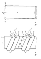
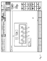
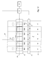
- Fig. 1 shows as an example of a printing machine schematically a four-high tower of a web press with both sides of a printing substrate 01, z. B. a paper web 01, employees printing cylinder 02, z. B. transfer cylinder 02, wherein two transfer cylinders 02 are employed in pairs against each other.
- To each side of the paper web 01 are for carrying out a multi-color printing, z. B. a four-color print each more, z. B. four transfer cylinders 02 arranged.
- the paper web 01 thus passes through four printing locations in its direction of transport T directed upwards from the bottom, on each of which one of the four printing inks of the four-color printing is applied to the paper web 01.
- the two first, ie lower, pressure points in the transport direction T of the paper web 01 form a lower printing unit in the four-high tower, whereas the two subsequent, ie upper, pressure points form an upper printing unit.
- the not shown forme cylinder fall under the name printing cylinder 02.
- the transfer cylinder 02 transferred in their respective axial direction side by side several print images on the web 01, z. B. at least two to eight printed images, each of the printed images with one of a plurality of transverse to the transport direction T of the paper web 01 juxtaposed sections 41; 42; 43; 44; 46; 47 correlates ( Fig. 10 ).
- the web press is z. B. used in newspaper printing.
- the printed on the respective transfer cylinders 02 side by side printed images each correspond to one side of a newspaper.
- Each multi-colored newspaper page consists of a precisely fitting, in the transport direction T of the web 01 consecutively executed overprint of several, z. B. four partial printing images or color separations, ie assigned between the individual each one ink, on the web 01 successively each same newspaper page printing color separations should not be inadmissible Passerdifferenzen.
- Fig. 2 indicates in a simplified representation of how a width B01 of the paper web 01 as it passes through in the Fig. 1 illustrated four-high tower in particular by a moisture absorption at the four successive pressure points preferably at the two in the transport direction T of the paper web 01 directed edges each by an amount of transverse strain ⁇ 01; ⁇ 02 widens, provided that no compensation of the fan-out effect takes place, wherein the transverse strain ⁇ 01; ⁇ 02 on both edges of the paper web 01 by no means must be equal in magnitude.
- a section 41 which correlates with this printed image also varies; 42; 43; 44; 46; 47 of the paper web 01 received amount of dampening solution, which in the respective section 41; 42; 43; 44; 46; 47 of the Paper web 01 sources, ie in particular their respective, possibly asymmetrical transverse strain ⁇ 01; ⁇ 02 caused.
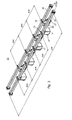
- Fig. 3 shows the orbit controller 03 of the Fig. 1 in an assembly representation, wherein the term of the assembly in the sense of DIN 6789 taken definitions is used.
- each actuator 04 is formed in each case as a controllable module 04 with a force acting on the paper web 01 actuating means 07, wherein the actuating means 07 in turn preferably as a deflectable, freely rotatably mounted roller 07 is formed.
- an action brought about by the adjusting means 07 is arranged in the plane of the paper web 01-executing actuator 13, this actuator 13, in the illustrated example, causing the deflection of the respective roller 07 ( Fig. 5 ), wherein with the respective deflection of at least one of the rollers 07, the paper web 01 in its width B01 z. B. is deformed wave-shaped and thereby a between different pressure points occurred register difference, in particular color register shift is corrected.
- rollers 07 Because the deflection of the rollers 07 takes place in each case in the plane of the paper web 01 in order to hire the rollers 07 to the paper web 01 or out of this plane for the purpose of parking the rollers 07 of the web 01, at the same time pivoted both sides in the plane of the web 01 Rollers 07 the paper web 01 in their width B01 wavy or S-shaped deform.
- the actuator 13 sets a control command of a control unit 33 (FIG. Fig. 9 ) in mechanical work, in particular in a running of the respective roller 07 movement to.
- the actuator 13 is z. B. formed as an electromechanical drive 13.
- a further exemplary embodiment of the actuator 13 may be in the form of a valve 13, which influences a flow, in particular the pressure of an air flow directed onto the plane of the paper web 01, by its opening or closing controlled by the control unit 33.
- the pressure set by the control unit 33 of the flow directed onto the plane of the paper web 01 corresponds to the actuating means 07 moved by the respective actuator 13 in the case of a mechanical image path controller 03.
- the actuators 13 are accordingly in each case the actuators in one of the control unit 33 influenced control chain or, if the control unit 33 is fed back a correlating with the setting of the actuating means 07 signal in a controlled by the control unit 33 control loop.
- each adjusting means 07 is an intensity of its engagement in the plane of the paper web 01 and thus a degree of deformation of the paper web 01 controlled by a control unit 33 to the actuator 13 control command or at least controllable and thus metered or at least metered, z. B.
- each roller 07 for the purpose of their deflection preferably a continuously adjustable adjustment S07 in the range z. B. between 10 mm and 50 mm, in particular between 15 mm and 25 mm.
- the modules 04 are z. B. by means of a bracket 08 and a detachable connection, for. As a screw, attached to the respective cross member 06, preferably clamped, wherein the respective traverse 06 z. B. as a preferably hollow profile bar with a z. B.
- the modules 04 are preferably arranged equidistantly at their respective traverse 06, z. B. each at a distance A04 of 200 mm to 400 mm, in particular 350 mm, said distance A04 z. B. the respective width of the sections 41; 42; 43; 44; 46; 47, in which the width B01 of the paper web 01 is divided ( Fig. 10 ).
- Each traverse 06 has z. B. a clear width or length L06 in the range of 1700 mm to 2400 mm, in particular between 1,900 mm and 2,000 mm.
- the modules 04 are along their respective traverse 06 are preferably arranged displaceably and can be freely positioned at their respective traverse 06, ie, in particular with regard to the width B01 of the paper web 01 at any desired locations.
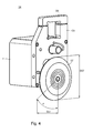
- Fig. 4 shows in an enlargement of one of the modules 04 with an associated along the displacement S07 deflectable roller 07.
- the adjustment S07 each roller 07 of the orginal controller 03 can z. B. at a press belonging to the control room z. B. from -25% to + 100% and be changed in this area, wherein at a setting of -25%, the respective roller 07 is pivoted from the plane of the paper web 01 maximum and therefore a retraction of the paper web 01 between the two spaced arranged trusses 06 is possible.
- At a setting of 0% is an orthogonal to the paper web 01 distance of z. B. 0.5 mm between the respective roller 07 and the paper web 01.
- each roller 07 has a diameter D07 in the range of z. B. 50 mm to 100 mm, in particular 60 mm to 80 mm.
- the bracket 08 of the module 04 is z. B.
- the mounting plate 09 carries on its one side a housing 11, in which at least the drive 13 is preferably arranged dust and moisture protected for adjusting the belonging to this module 04 roller 07, and to its other side z.
- a connected to the drive shaft 13 14 passes through the mounting plate 09.
- the roller 07 supporting the lever 12 is fixedly connected to this shaft 14.
- the lever 12 and thus the one on it Axle pivot freely rotatably mounted roller 07 deflected.
- the displacement S07 of the roller 07 may be limited in their two deflection directions each by a mechanical stop, which protrudes in each case from the mounting plate 09 and against the z. B. the roller 07 supporting lever 12 abuts in an inadmissible rotational movement of the shaft 14.
- the arranged in the housing 11 of the module 04 actuator 13 is in the preferred embodiment as a drive 13 for adjusting the belonging to this module 04 roller 07 z. B. as an electrically driven motor 13, in particular as a stepper motor 13, preferably as a Klauenpol Colourmotor 13, z. B. formed as a 2-phase stepping motor 13, the winding z. B. is switched unipolar.
- the motor 13 by means of a rotation of the shaft 14 driven by it, preferably adjusts the adjustment path S07 of the roller 07 of the relevant setting unit 04 via the gear 16 coupled to it.
- the maximum of the roller 07 to be executed adjustment S07 requires z. B. a rotation angle ⁇ of the shaft 14 in the range of only 30 ° to 60 °, in particular 40 ° to 45 ° ( Fig. 4 ), wherein the transmission 16 z. B. performs a total of between 1,000 and 2,500 steps, in particular 1,800 to 2,000 steps.
- a provided in or on the housing 11 of the module 04, preferably connected to the driven shaft 14 potentiometer is used to detect the angular position of this shaft 14th
- the respective actuator 13 for adjusting the belonging to this module 04 roller 07 z. B. at least supplied with electrical energy in connection with a constant voltage.
- a bidirectional communication gestattende line connection 17 is preferably also designed as a data interface 17, with which the actuator 13 of the respective module 04 is connected to a digital network 34 for data exchange or at least attachable.
- the data interface 17 is preferably a the respective actuator 13 at least with respect to the control unit 33 identifying electronic address impressed.
- a measured value provided by the potentiometer with respect to the angular position of the shaft 14 to the z. B.
- the drive 13 controlling the control unit 33, whereby a closed loop is formed with respect to the control exercised by the control unit 33.
- a directed from the potentiometer via the control unit 33 to the drive 13 data flow is used in particular in an automatically running loop for setting and / or tracking of the respective actuating means 07.
- the physical line management belonging to the digital network 34 preferably takes place initially in or along the traverse 06 carrying the module 04 and then on to the control unit 33, which is preferably arranged outside the printing unit.
- the digital network 34 is generally a plurality of different, with the control unit 33 Data exchanging aggregates connected, but at least all actuators 13 of the image path controller 03.
- the control unit 33 may, for. B. be integrated in the belonging to the printing press control room.
- the drive 13 and / or the potentiometer, and the control unit 33 preferably takes place via a line system 34, which is designed as the digital network 34, said line system 34 may be integrated into a network for controlling the printing press.
- the network 34 via which the control unit 33 exchanges data between it and at least the respective actuator 13 to be controlled of the image path controller 03, is a network for controlling arranged in the printing machine units, z.
- an inking unit and / or a dampening unit which are involved in a running in the printing press printing process.
- Each of the rollers 07 of the in the Fig. 3 illustrated image controller 03 is from the control unit 33, z. B. of the press belonging to the control station, individually and independently of the other rollers 07 of this orbit controller 03 set in their respective adjustment S07 or at least adjustable.
- each belonging to a Jardinbahnregler 03 module 04 is individually addressed from the control center or at least addressable, ie based on an individual, the respective module 04 associated, in particular unique address selectively set from the control center or at least adjustable.
- the respective actuator 13 of the actuating units 04 is assigned an electronic address identifying it in the digital network 34, by means of which a specific one of the plurality of actuators 13 connected to the digital network 34 can be selected, and the actuator 13 selected by the latter z. B.
- FIG. 2 illustrates in a block diagram the control or regulation in a device comprising the already mentioned control unit 33 and the above-described multiple track 04 having image path controller 03.
- Adjusting means 07 assigned to this paper web 01 are preferably used simultaneously by the control unit 33, but in opposite directions, so that these adjusting means 07 move in pairs either toward one another or away from each other (FIG. Fig. 11 ).
- the control room has, as in the Fig. 9 indicated, at least via a display device 36, to which various program masks 18 are displayed, and via an operating unit 37, with which values can be manually entered or with which in at least one of the program masks 18 displayed values are selectable.
- Fig. 6 shows, by way of example, such a program mask 18 displayed on the control station, in the left lower area of which a particular printing tower of the printing press is shown schematically and selected or at least selectable by means of at least one button 19.
- a particular printing tower of the printing press is shown schematically and selected or at least selectable by means of at least one button 19.
- the upper left area of the Fig. 6 shown can then in the selected printing tower of z. B. between the lower and the upper pressure unit of this printing tower arranged image path controller 03 are selected based on at least one other button 21, in which case the adjustment S07 z. B.
- each individual roller 07 z. B. by means of sliders 22 or by a numerical input in the individual rollers 07 associated input fields 23 can be adjusted. If all rollers 07 are to be adjusted in the same way, a numerical input can also be made in an input field 24 serving for overall adjustment.
- the input in the input fields 23; 24 concerns z. B. on the ranging from -25% to + 100% range S07 percentages, which z. B. can then be visualized by a corresponding positioning of the slider 22 in their respective adjustment and / or by a display of this numerical value.
- Fig. 7 indicates alternatively Fig. 6 a further program mask 18, in which in respective input fields 23 for each of the roller 07 of a selected orbital controller 03, a numerical value, in particular a percentage, for the respective displacement S07 of the respective roller 07 can be entered.
- a numerical input for a uniform adjustment of all belonging to this image path controller 03 rollers 07 can be entered.
- the example shown shows a compensation value of 15%.
- the program masks 18 of the Fig. 7 and Fig. 6 is common that on the one hand an individual setting of several, preferably all belonging to a particular image controller 03 rollers 07 is provided, but on the other hand it is also possible to impose on these individual settings an input common compensation value.
- This compensation value which applies to all rollers 07, alters all individual settings in the same way. For example, it adds an input compensation value of 15% to all individual settings.
- the intensity of the fan-out effect depends inter alia on the production speed of the printing press, ie on the speed of its printing cylinder 02, in particular transfer cylinder 02 (FIG. Fig. 1 ). There is also a dependence of the intensity of the fan-out effect of properties of the printing substrate 01, z. B. of a grammage of the paper used.
- Fig. 8 shows an example displayed on the control panel or at least displayable program mask 18, which contains at least one graph 26 with a course of a above the rotational speed of the printing cylinder 02 applied compensation curve 27, wherein the compensation curve 27 respectively those z. B. percentage compensation value indicates that all associated with a particular image controller 03 rollers 07 is stamped in association with the speed of the printing cylinder 02.
- a plurality of compensation curves 27 are preferably stored, wherein each of these compensation curves 27 z.
- B. a property of the printing material 01 is associated, for. B. the grammage of the paper used.
- Each of these compensation curves 27 can be called up on the program mask 18 by a corresponding selection.
- compensation curve 27 applies to a paper with the grammage of 45 g / m 2 .
- the course of each compensation curve 27 is defined by several support points 28 or at least fixed, the support points 28 the traversed by the printing press range of production speed from its standstill to its maximum speed z. B. divide evenly. The number of nodes 28 may be for each compensation curve 27 z.
- B. based on a Numeric input in an input field 31 can be freely defined or at least definable. It can z. B. ten support points 28 may be provided, which from standstill to the maximum speed of z. B. divide 45,000 cylinder revolutions per hour reaching range of production speed in nine equal speed intervals.
- the compensation value belonging to the respective values of the production speed is e.g. B. in a diagram 26 associated table 29 editable, ie there numerical values for the respective nodes 28 can be entered. From the numerical values entered in Table 29 for the respective interpolation points 28, the graph of the relevant compensation curve 27 is then generated by the control unit 33 in the diagram 26 by a line connecting the interpolation points 28.
- the course of the respective compensation curve 27 displayed in the diagram 26 can be changed, for. B. the course of the respective compensation curve 27 can be raised or lowered as a whole, wherein the value by which the course of the respective compensation curve 27 is to be changed, can be entered as an absolute value or as a relative value.
- several different adjustable compensation curves 27 are in the memory of the control unit 33 in association with selected productions, z.
- selected productions z.
- d. H. To a type of paper, and / or to selected printing towers, d. H. to a print location, stored or at least storable and can be invoked on program mask 18 from memory as a default.
- the control unit 33 proposes for the respective print locations, i. H. for the respective printing towers of the printing press, certain default settings for the adjustment path S07 of the respective rollers 07 of the image path controller 03 acting on the relevant printing location before and / or sets these default values automatically or after a release by the operator of the printing machine.
- settings of the adjustment S07 of each roller 07 of a particular image controller 03 in an ongoing production of the printing machine automatically z. B. be tracked by a managed by the control unit 33 control loop or by a new manual input to the control unit 33.
- the control executed by the control unit 33 can also be carried out fully automatically without manual intervention, which will be described below by way of example in connection with FIG Fig. 10 is explained.
- the method is thus carried out in a printing press which prints a plurality of inks in the same production process.
- the form cylinder of the printing press used is z. B. formed as a 6/2-forme cylinder, wherein in this example on the lateral surface in the axial direction six printing plates next to each other and at each axial mounting position two printing plates are arranged in its circumferential direction.
- the fixed with respect to the paper web 01 sections 41; 42; 43; 44; 46; 47 are preferably each of equal width B41; B42; B43; B44; B46; B47.
- the width B41; B42; B43; B44; B46; B47 of the respective sections 41; 42; 43; 44; 46; 47 corresponds z. B.
- each with a transversely to the transport direction T of the web 01 directed width of the arranged on the respective with the respective transfer cylinder 02 form cylinder arranged printing forms.
- Example shown are on both sides of a web of paper 01 in the transport direction T centrally passing symmetry line 48 each three of the aforementioned sections 41; 42; 43; 44; 46; 47 provided, wherein each of the symmetry line 48 adjacent sections 43; 44 define a center region of this paper web 01, whereas the regions farthest from the symmetry line 48 41; 47 are each considered to be associated with an edge region of this paper web 01.
- a section 43; 44 is arranged as lying in the middle region of the paper web 01 when it adjoins the line of symmetry 48 passing through the paper web 01 or is passed through by this line of symmetry 48.
- the newspaper involved printing cylinder 02 is in several, preferably in each of these juxtaposed sections 41; 42; 43; 44; 46; 47 each a mark M41; M42; M43; M44; M46; M47 printed on the web 01
- the respective marking M41; M42; M43; M44; M46; M47 may be a one-piece or multi-part mark specially printed to determine registration differences, e.g. B. be a so-called register mark of different geometry.
- the mark M41; M42; M43; M44; M46; M47 can but also a not in addition to the printed image of the respective page of the newspaper to be produced applied significant area in this printed image.
- a one-piece or multi-part detection device 49 detects z. B. optically, in particular by a respective marking M41; M42; M43; M44; M46; M47 imaging method, preferably photographic, d. H. by a photographic image, one or more of the marks M41 printed on the surface of the paper web 01; M42; M43; M44; M46; M47.
- the detection device 49 has the respective with respect to the paper web 01 juxtaposed sections 41; 42; 43; 44; 46; 47 associated detectors 51; 52; 53; 54; 56; 57, each detector 51; 52; 53; 54; 56; 57 preferably exactly one of these sections 41; 42; 43; 44; 46; 47 is assigned.
- the detectors 51; 52; 53; 54; 56; 57 are each formed as separate components, for. B. each as a scanner or as a camera. In an alternative embodiment of the detection device 49, at least the respective sections 41; 42; 43; 44; 46; 47 associated detection areas 51; 52; 53; 54; 56; 57 provided within a trained as a single assembly detection unit, these detection areas 51; 52; 53; 54; 56; 57 each exactly one of the sections 41; 42; 43; 44; 46; 47 are assigned.
- the respective detectors 51; 52; 53; 54; 56; 57 or detection areas 51; 52; 53; 54; 56; 57 are z. B. individually and independently z. B. activated by a control unit 33.
- one of the sections 41; 42; 43; 44; 46; 47 associated detection areas 51; 52; 53; 54; 56; 57 is measured simultaneously or that all respective detectors 51; 52; 53; 54; 56; 57 simultaneously perform their respective measurement.
- the detection device 49 converts z. B. from the respective detectors 51; 52; 53; 54; 56; 57 or detection areas 51; 52; 53; 54; 56; 57 made mapping of at least one of the printed on the surface of the paper web 01 marks M41; M42; M43; M44; M46; M47 in a preferably electrical, in particular digital Signal to and passes this signal to the control unit 33, which in turn emits an actuating signal to at least one actuator 07 of the image controller 03, wherein this made by the control unit 33 adjustment of the at least one control element 07 in particular in an ongoing production of the printing machine.
- control unit 33 Since the control unit 33 carries out this adjustment of the at least one adjusting element 07 automatically on the basis of the signal of the detection device 49, the control unit 33 has the functionality of a control device 33.
- the detection device 49 can also be used for further control tasks and / or quality checking tasks in the printing press by the signal generated by the detection device 49 is evaluated with respect to various criteria.
- a plurality of actuators 07 having image path controller 03 is operated in the preferred embodiment such that one of the transverse to the transport direction T of the printing substrate 01 juxtaposed portions 41; 42; 43; 44; 46; 47 detected marks M41; M42; M43; M44; M46; M47 z. B. is selected by the control device 33 as a reference and set for the subsequent control method as such, wherein z. B. a mark M43; M44 from one of the middle region of the printing substrate 01 attributable sections 43; 44 is selected as a reference.
- a mark M43; M44 from one of the middle region of the printing substrate 01 attributable sections 43; 44 is selected as a reference.
- the marking M43 has been selected as a reference from the section 43, which is viewed on the left in the direction of transport T of the printing material web, and is adjacent to the line of symmetry 48.
- one of the other markings M41 would have; M42; M44; M46; M47, z. B.
- the marker M44 in the right of the line of symmetry 48 adjacent section 44 can be selected as a reference.
- the marking M43 selected as a reference in this example thus lies in a section 43, which extends transversely to the transport direction T of the printing material web 01 on both sides in each case to a further section 42; 44 of this printing material 01 adjacent.
- a determination of the transverse strain ⁇ 01 made in the printing substrate web 01; ⁇ 02 serving method provides, for example, that then z. B. from the controller 33, a distance A41; A42; A43; A44; A46; A47 between the marker M41 selected as the reference; M42; M43; M44; M46; M47 and the at least one other mark M41 detected at the second time; M42; M43; M44; M46; M47 is determined, this determined distance A41; A42; A43; A44; A46; A47 is compared with its value which it has during the printing of these marks M41; M42; M43; M44; M46; M47 had the first time.
- an undesirable z. B. caused by fan-out width expansion of the substrate web 01 each with respect to a reference selected as the reference marker M43 starting from a z. B. in the middle or near the middle of the printing substrate 01 lying section 43 is gradually adjusted by a from the detection of marks M41; M42; M44; M46; M47 value of a distance A41 related to the reference selected mark M43; A42; A44; A46; A47 is in each case adjusted to its value determined by the fact that the respective section 41; 42; 44; 46; 47 associated actuator 07 is re-adjusted with respect to its effect on the relevant substrate web 01.
- This method described here by way of example for compensating for the elongation of the width meets the experience that the z.
- the width increase relative to the symmetry line 48 or selected as the reference marker M43 may be both symmetrical and asymmetrical.
- the width expansion of the printing material 01 in their different sections 41; 42; 44; 46; Be different, which is a differentiated setting of or the respective section 41; 42; 44; 46; 47 associated adjusting elements 07 requires.
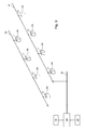
- Fig. 11 shows a schematic partial view of an arrangement of arranged on both sides of the web 01 positioning elements 07 of the image controller 03, wherein arranged on the same side of the paper web 01 positioning elements 07 are each arranged in a direction parallel to the width B01 of this paper web 01 distance A04 ( Fig. 3 ).
- Two arranged on different sides of the paper web 01 actuators 07 work in pairs together by these adjusting means 07 are brought by the control unit 33 simultaneously, but in opposite directions, so that these adjusting means 07 in pairs either move towards each other or move away from each other.
- a pair of cooperating actuating means 07 is in the z. B. the width B43 and B44 having sections 43; 44, each with one of its edges z. B.
- the respective printing cylinder 02 involved in the printing are thus each first in certain, soregisterabweichungen reducing manner arranged relative to each other before the actual compensation of the fan-out caused transverse strain .DELTA.01; ⁇ 02 of the substrate web 01 takes place. This is for the actual compensation of the fan-out caused transverse strain ⁇ 01; .DELTA.02 of the substrate web 01 created a more favorable starting position. Because in the manner described above, aligned in the side register arrangement of the relevant participating in the printing cylinder unit 02 causes the respective sections 41; 42; 43; 44; 46; 47 assigned adjusting means 07 of the orbit controller 03 intervene less intensively in the printing substrate 01 (must).
- This has the advantage that the risk of scratching and / or slitting of the printing material web 01 is reduced by one of the adjusting means 07 of the image web controller 03 participating in the fan-out compensation and / or a tendency to wrinkling of this printing material web 01, which is particularly advantageous for a very thin and / or less tear-resistant printing substrate 01.
- the proposed method thus favors the avoidance of mechanical damage to the printing substrate 01 by at least one participating in the fan-out compensation adjusting means 07 of the image path controller 03.
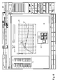
- FIG. 12 shows simplified and schematically the apparatus for performing the proposed method with a preferably printed on both sides of substrate web 01, the transport direction T is indicated by an arrow.
- This substrate web 01 is covered by several, z. B. four successively arranged in the transport direction T printing cylinders 02 z. B. printed in an offset printing process, as it is z. B. in the Fig. 1 is shown.
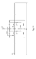
- Fig. 12 By way of example, only one of these printing cylinder 02 is shown, wherein this as well as the other printing cylinder 02 along their respective axis of rotation 38 in each case more, z. B. six pressure points a; b; c; d; e; have f.
- Each of these pressure points a; b; c; d; e; f is in each case exactly one of the transverse to the transport direction T juxtaposed preferably each equal width sections 41; 42; 43; 44; 46; 47 assigned ( Fig. 10 ).
- Fig. 12 is a the printing material 01 in the transport direction T continuous symmetry line 48 indicated, wherein on both sides of this symmetry line 48 each at least one of the sections 41; 42; 43; 44; 46; 47, preferably each more, z. B. three sections 41; 42; 43; 44; 46; 47 are arranged.
- the pressure points a; b; c; d; e; f are z. B.
- Operating position shown by way of example captures the detection device 49 a marking M43 applied to the printing material web 01 by means of the printing location d.
- the respective operating positions of the detecting means 49 for detecting the respective mark M41; M47 in the "outer" sections 41; 47 are indicated.
- the respective marks M41; M42; M43; M44; M46; M47 are preferably in the middle of each of the sections 41; 42; 43; 44; 46; 47 arranged what in the Fig. 12 is indicated by dashed lines, wherein the detection means 49 each to this position in the respective sections 41; 42; 43; 44; 46; 47 is aligned.
- the detection device 49 is z. B. able to mark all marks M41; M42; M43; M44; M46; M47 in all transverse to the transport direction T juxtaposed sections 41; 42; 43; 44; 46; 47 at the same time or in preferably chronologically short steps to capture.
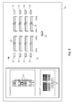
- Fig. 13 shows an example of another program mask 18, as z. B. at one Display device 36 of belonging to the printing press control station is displayed or at least displayable.
- upper portion of this program mask 18 are of the detection device 49 in the transverse to the transport direction T juxtaposed sections 41; 42; 43; 44; 46; 47 detected, on the substrate web 01 preferably in each case multi-part formed markings M41; M42; M43; M44; M46; M47 each in the form z. B. of trademark fields in a row next to each other.
- the immediately adjacent to the printing substrate 01 in the transport direction T continuous line of symmetry 48 adjacent section 43 has been selected in this example as a reference and is therefore preferably shown highlighted on the program screen 18, z. B.
- z. B from the control unit 33 first for the involved in the printing process cylinder unit 02 color register set to its desired value, with a selected in this selected section 43 actual value and provided for this section 43 setpoint of the color register respectively by the respective position or the respective arrangement the relevant mark M43 are given in the relevant reference selected section 43, wherein z. B.
- control unit 33 performs a comparison of the determined actual value with the predetermined target value and at a certain tolerance limit exceeding and thus impermissible deviation between the actual value and the desired value involved in the printing process printing cylinder 02 repositioned relative to each other by at least one of these printing cylinder 02 at least is readjusted in its axial position and / or in its rotational angle position.
- Fig. 13 shows the mark M43 of the reference-selected portion 43 in an arrangement which is e.g. B.
- the respective position or the respective arrangement of the respective marks M41; M42; M44; M46; M47 is different from the location or arrangement of the respective marker M43 in the reference-selected portion 43, which means that the respective color register in the remaining portions 41; 42; 44; 46; 47 each of which for the respective section 41; 42; 44; 46; 47 deviates setpoint of the color register.
- all the markers M41 usually deviate; M42; M43; M44; M46; M47 in their respective position or the arrangement of their respective brands or brand elements relative to each other.
- the existing page register deviations are now z. In start-up area A or in run-up area B ( Fig.
- the control unit 33 determines for each relevant ink, ie for each respective printing cylinder 02 an average of all determined for this printing cylinder 02 page register deviations. It can be provided that a particularly high value for a page register deviation that does not appear plausible in the context of the other values of the respectively determined page register deviations, such as the one shown on the program mask 18 z.
- control unit 33 After by the control unit 33 preferably at least for all the colors involved in the printing and for all involved in the pressure transversely to the transport direction T juxtaposed pressure points a; b; c; d; e; f and their associated sections 41; 42; 43; 44; 46; 47, the respective page register deviations have been determined, all determined values of these page register deviations between the respective markings M41; M42; M43; M44; M46; M47 of immediately adjacent portions 41; 42; 43; 44; 46; 47 by a in the Fig.
- the compensation of fan-out induced transverse strain ⁇ 01; ⁇ 02 of the printing material web 01 by the at least one adjusting means 07 of the image path controller 03 is carried out according to the proposed method only after at least one of the relevant pressure cylinder concerned 02 has been displaced along its respective axis of rotation 38 by the maximum amount corresponding to the predetermined barrier value and so some leveling or equalization of the page register deviations has taken place.
- the respective printing cylinder 02 formed as a forme cylinder is displaced axially in the manner described.
- the proposed method thus provides a special, particularly advantageous starting situation for carrying out the compensation of a fan-out-related transverse strain ⁇ 01; ⁇ 02 a printing substrate printed in a printing machine with multiple printing inks ready when at least one adjusting means 07 of an image controller 03 is used for this compensation.
- a reference preferably that of the juxtaposed portions 41; 42; 43; 44; 46; 47 selected, in which the most uniform and thus best leveling of the side register deviations is achieved by the axial displacement of the printing cylinder 02 involved in the printing process in question.
- This selection makes the control unit 33 on the basis of a comparison of its from the respective sections 41; 42; 43; 44; 46; 47 and / or based on the respective sections 41; 42; 43; 44; 46; 47 results obtained.
- the best leveling of the page register deviations is achieved when, taking into account preferably several, in particular all printing inks involved in the printing, in particular the chromatic colors, z.
- a respective formed from the respective determined page register deviations mean value after execution of the axial displacement of at least one of the pressure cylinder involved in the respective printing process cylinder 02 by the maximum the predetermined threshold amount corresponding to a reduced compared to the original situation, preferably assumes its absolute value as low as possible.
- a method for compensating a fan-out conditional transverse strain ⁇ 01; ⁇ 02 of a printing material web 01 printed in a printing machine having a plurality of printing inks, one printing cylinder 02 being used for the printing of each of these printing inks, a section 43 of sections 41, 41 arranged side by side on the printing material web 01 in a row transverse to its transport direction T; 42; 43; 44; 46; 47 is selected as a reference for setting a valid for the participating printing unit cylinder 02 color register, wherein in each of the juxtaposed sections 41; 42; 43; 44; 46; 47 on the substrate web 01 in each case detectable by a detection device 49 marking M41; M42; M43; M44; M46; M47 is mounted, wherein for the selected as the reference section 43 using the detected in this section 43 of the detection means 49 marking M43 applicable to the pressure cylinder 02 involved color register is set, wherein thereafter for at least one of the printing cylinder 02 involved in the pressure first at least one between the immediately
- the respective value of the page register deviations determined for the relevant printing cylinder 02 is reduced in particular by the displacement of the relevant printing cylinder 02 along its axis of rotation 38 by a maximum amount corresponding to a predetermined threshold value, if the respective determined value of at least one of the page register deviations greater than the predetermined Is the barrier value.
- the threshold value a value within a range of ⁇ 0.1 mm is preferably used.
- the compensation of fan-out induced transverse strain ⁇ 01; ⁇ 02 of the printing material web 01 is advantageously carried out after several or all of the printing units 02, each printing a color ink, have been displaced along their respective axis of rotation 38 by the maximum amount corresponding to the predetermined barrier value.
- a value determined for one of the page register deviations is then ignored by the control unit 33 in a preferred embodiment, although this value is greater than the predetermined threshold value, but in relation to the values of the remaining page register deviations is not plausible.
- the respective value for the respective page register deviation is preferably displayed graphically and / or numerically in a program mask 18 of a display device 36.
- a desired value of the color register and / or the threshold value is or will be z. B.
- the proposed method is carried out in particular in a four-high tower of a web press, wherein the web press in their printing process z. B. a wet offset printing method used.
- the page register deviations are z. B. determined in a start-up area A or in a run-up area B or in the continuous printing of the web press.
Landscapes
- Engineering & Computer Science (AREA)
- Mechanical Engineering (AREA)
- Inking, Control Or Cleaning Of Printing Machines (AREA)
Applications Claiming Priority (1)
| Application Number | Priority Date | Filing Date | Title |
|---|---|---|---|
| DE102013214566.7A DE102013214566B4 (de) | 2013-07-25 | 2013-07-25 | Verfahren zur Kompensation einer Fan-out bedingten Querdehnung einer in einer Druckmaschine mit mehreren Druckfarben bedruckten Bedruckstoffbahn unter Verwendung von mindestens einem Stellmittel eines Bildbahnreglers |
Publications (3)
| Publication Number | Publication Date |
|---|---|
| EP2829401A2 true EP2829401A2 (fr) | 2015-01-28 |
| EP2829401A3 EP2829401A3 (fr) | 2015-09-16 |
| EP2829401B1 EP2829401B1 (fr) | 2018-11-14 |
Family
ID=50677942
Family Applications (1)
| Application Number | Title | Priority Date | Filing Date |
|---|---|---|---|
| EP14166158.7A Active EP2829401B1 (fr) | 2013-07-25 | 2014-04-28 | Procédé de compensation d'une dilatation transversale consécutive à l'allongement en éventail d'une bande de matériau imprimée à l'aide de plusieurs couleurs d'impression dans une imprimante |
Country Status (2)
| Country | Link |
|---|---|
| EP (1) | EP2829401B1 (fr) |
| DE (1) | DE102013214566B4 (fr) |
Cited By (1)
| Publication number | Priority date | Publication date | Assignee | Title |
|---|---|---|---|---|
| CN109789696A (zh) * | 2016-07-13 | 2019-05-21 | 小森公司 | 有价证券的文字或号码检查装置以及文字或号码检查方法 |
Citations (7)
| Publication number | Priority date | Publication date | Assignee | Title |
|---|---|---|---|---|
| DE29501373U1 (de) | 1995-01-30 | 1995-04-27 | MAN Roland Druckmaschinen AG, 63075 Offenbach | Vorrichtung zur Korrektur des Fan-Out-Effekts an Rollenrotationsdruckmaschinen |
| DE19529430A1 (de) | 1995-07-06 | 1997-01-16 | Baumueller Nuernberg Gmbh | Elektrisches Antriebssystem und Sicherheitsmodul insbesondere in einer Bogendruckmaschine |
| DE10244437A1 (de) | 2002-09-24 | 2004-04-01 | Maschinenfabrik Wifag | Verfahren und Vorrichtung zur Bestimmung der Position und/oder Form von Marken auf einer bedruckten Papierbahn |
| DE10352619A1 (de) | 2003-07-11 | 2005-02-10 | Koenig & Bauer Ag | Verfahren und Vorrichtung zur Beeinflussung des Fan-Out-Effektes |
| DE102004004264A1 (de) | 2004-01-28 | 2005-09-01 | Koenig & Bauer Ag | Verfahren zur Kompensation einer Querdehnung und/oder einer Längsdehnung eines Bedruckstoffes und Druckmaschine mit mehreren mindestens ein Druckbild auf einem Bedruckstoff erzeugenden Druckwerken |
| DE102008001367A1 (de) | 2008-04-24 | 2009-10-29 | Koenig & Bauer Aktiengesellschaft | Verfahren zum Betrieb eines in einer Druckmaschine angeordneten mehrere Stellelemente aufweisenden Bildbahnreglers |
| EP2447071A1 (fr) | 2009-06-25 | 2012-05-02 | Mitsubishi Heavy Industries Printing & Packaging Machinery, Ltd. | Dispositif de correction d'alignement en largeur, imprimante et procédé de correction d'alignement en largeur |
Family Cites Families (4)
| Publication number | Priority date | Publication date | Assignee | Title |
|---|---|---|---|---|
| JP2566897B2 (ja) * | 1992-07-29 | 1996-12-25 | 株式会社東京機械製作所 | 多色刷平版印刷機 |
| DE59706517D1 (de) * | 1996-10-25 | 2002-04-11 | Koenig & Bauer Ag | Anordnung zur korrektur des fan-out-effektes an rollenrotationsdruckmaschinen |
| DE59902522D1 (de) * | 1998-04-22 | 2002-10-10 | Wifag Maschf | Registerhaltiger Antrieb eines Druckzylinders oder einer Schnittregisterwalze einer Rotationsdruckmaschine |
| DE102007035692B4 (de) * | 2007-07-30 | 2011-12-01 | Koenig & Bauer Aktiengesellschaft | Bildbahnregler einer Druckmaschine |
-
2013
- 2013-07-25 DE DE102013214566.7A patent/DE102013214566B4/de not_active Expired - Fee Related
-
2014
- 2014-04-28 EP EP14166158.7A patent/EP2829401B1/fr active Active
Patent Citations (7)
| Publication number | Priority date | Publication date | Assignee | Title |
|---|---|---|---|---|
| DE29501373U1 (de) | 1995-01-30 | 1995-04-27 | MAN Roland Druckmaschinen AG, 63075 Offenbach | Vorrichtung zur Korrektur des Fan-Out-Effekts an Rollenrotationsdruckmaschinen |
| DE19529430A1 (de) | 1995-07-06 | 1997-01-16 | Baumueller Nuernberg Gmbh | Elektrisches Antriebssystem und Sicherheitsmodul insbesondere in einer Bogendruckmaschine |
| DE10244437A1 (de) | 2002-09-24 | 2004-04-01 | Maschinenfabrik Wifag | Verfahren und Vorrichtung zur Bestimmung der Position und/oder Form von Marken auf einer bedruckten Papierbahn |
| DE10352619A1 (de) | 2003-07-11 | 2005-02-10 | Koenig & Bauer Ag | Verfahren und Vorrichtung zur Beeinflussung des Fan-Out-Effektes |
| DE102004004264A1 (de) | 2004-01-28 | 2005-09-01 | Koenig & Bauer Ag | Verfahren zur Kompensation einer Querdehnung und/oder einer Längsdehnung eines Bedruckstoffes und Druckmaschine mit mehreren mindestens ein Druckbild auf einem Bedruckstoff erzeugenden Druckwerken |
| DE102008001367A1 (de) | 2008-04-24 | 2009-10-29 | Koenig & Bauer Aktiengesellschaft | Verfahren zum Betrieb eines in einer Druckmaschine angeordneten mehrere Stellelemente aufweisenden Bildbahnreglers |
| EP2447071A1 (fr) | 2009-06-25 | 2012-05-02 | Mitsubishi Heavy Industries Printing & Packaging Machinery, Ltd. | Dispositif de correction d'alignement en largeur, imprimante et procédé de correction d'alignement en largeur |
Cited By (2)
| Publication number | Priority date | Publication date | Assignee | Title |
|---|---|---|---|---|
| CN109789696A (zh) * | 2016-07-13 | 2019-05-21 | 小森公司 | 有价证券的文字或号码检查装置以及文字或号码检查方法 |
| CN109789696B (zh) * | 2016-07-13 | 2021-01-29 | 小森公司 | 有价证券的文字或号码检查装置以及文字或号码检查方法 |
Also Published As
| Publication number | Publication date |
|---|---|
| DE102013214566B4 (de) | 2015-02-05 |
| DE102013214566A1 (de) | 2015-01-29 |
| EP2829401A3 (fr) | 2015-09-16 |
| EP2829401B1 (fr) | 2018-11-14 |
Similar Documents
| Publication | Publication Date | Title |
|---|---|---|
| DE69606076T2 (de) | Bildkompensation mittels gedruckter Referenzmarken | |
| EP1644192B1 (fr) | Procede pour influer sur le phenomene de tuilage par un dispositif | |
| EP2392459B1 (fr) | Procédé et dispositif de réglage du registre d'une presse d' impression | |
| DE10132266B4 (de) | Verfahren zur Regelung des Übergabepassers in einer Bogenrotationsdruckmaschine | |
| EP3539777B1 (fr) | Procédé et dispositif de correction d'une position d'impression d'un groupe d'impression ainsi que imprimante | |
| DE19781048B4 (de) | Druckeinrichtung | |
| DE29501373U1 (de) | Vorrichtung zur Korrektur des Fan-Out-Effekts an Rollenrotationsdruckmaschinen | |
| DE29718968U1 (de) | Anordnung zur Korrektur des Fan-Out-Effektes an Rollenrotationsdruckmaschinen | |
| WO2004048092A2 (fr) | Procede et dispositif pour regler le registre d'une machine d'impression | |
| DE102005019566A1 (de) | Druckmaschine und Verfahren zur Registerkorrektur | |
| WO2014020083A2 (fr) | Procédé de réglage de la longueur d'impression d'une image d'impression dans une rotative polychrome | |
| DE102004004264A1 (de) | Verfahren zur Kompensation einer Querdehnung und/oder einer Längsdehnung eines Bedruckstoffes und Druckmaschine mit mehreren mindestens ein Druckbild auf einem Bedruckstoff erzeugenden Druckwerken | |
| EP2829401B1 (fr) | Procédé de compensation d'une dilatation transversale consécutive à l'allongement en éventail d'une bande de matériau imprimée à l'aide de plusieurs couleurs d'impression dans une imprimante | |
| EP1135256A1 (fr) | Procede de regulation d'un registre | |
| EP1759844B1 (fr) | Procédé pour corriger l'impression | |
| EP1708886B1 (fr) | Machine a imprimer faisant appel a un dispositif et a un procede pour compenser un allongement longitudinal et un allongement transversal d'une bande de matiere d' impression imprimee dans differents groupes d'impression | |
| EP2025513B1 (fr) | Procédé destiné au fonctionnement d'un dispositif de réglage de bande d'image d'une imprimante | |
| DE102008001367B4 (de) | Verfahren zum Betrieb eines in einer Druckmaschine angeordneten, mehrere Stellelemente aufweisenden Bildbahnreglers | |
| DE102006018462B4 (de) | Verfahren zum Steuern und/oder Regeln eines Registers in einer Druckmaschine | |
| DE102005021148B3 (de) | Verfahren zur Regelung eines Umfangsregisters in einer Druckmaschine | |
| WO2006117291A2 (fr) | Procede pour piloter et/ou reguler un reperage dans une machine a imprimer, ainsi que dispositif pour piloter et/ou reguler un reperage circonferentiel | |
| DE102015200148B4 (de) | Verfahren zur Anpassung mindestens einer Länge einer auf mehreren Druckbogen jeweils gleich groß drucktechnisch auszubildenden Fläche | |
| DE102007035692B4 (de) | Bildbahnregler einer Druckmaschine | |
| EP1980396A2 (fr) | Procédé destiné déplacer des modules de machines d'impression | |
| DE102007035688B4 (de) | Verfahren zum Betrieb eines Bildbahnreglers einer Druckmaschine |
Legal Events
| Date | Code | Title | Description |
|---|---|---|---|
| 17P | Request for examination filed |
Effective date: 20140428 |
|
| AK | Designated contracting states |
Kind code of ref document: A2 Designated state(s): AL AT BE BG CH CY CZ DE DK EE ES FI FR GB GR HR HU IE IS IT LI LT LU LV MC MK MT NL NO PL PT RO RS SE SI SK SM TR |
|
| AX | Request for extension of the european patent |
Extension state: BA ME |
|
| PUAI | Public reference made under article 153(3) epc to a published international application that has entered the european phase |
Free format text: ORIGINAL CODE: 0009012 |
|
| PUAL | Search report despatched |
Free format text: ORIGINAL CODE: 0009013 |
|
| RAP1 | Party data changed (applicant data changed or rights of an application transferred) |
Owner name: KOENIG & BAUER AG |
|
| AK | Designated contracting states |
Kind code of ref document: A3 Designated state(s): AL AT BE BG CH CY CZ DE DK EE ES FI FR GB GR HR HU IE IS IT LI LT LU LV MC MK MT NL NO PL PT RO RS SE SI SK SM TR |
|
| AX | Request for extension of the european patent |
Extension state: BA ME |
|
| RIC1 | Information provided on ipc code assigned before grant |
Ipc: B41F 7/12 20060101AFI20150812BHEP Ipc: B41F 13/14 20060101ALI20150812BHEP Ipc: B41F 33/00 20060101ALI20150812BHEP |
|
| R17P | Request for examination filed (corrected) |
Effective date: 20150909 |
|
| GRAP | Despatch of communication of intention to grant a patent |
Free format text: ORIGINAL CODE: EPIDOSNIGR1 |
|
| STAA | Information on the status of an ep patent application or granted ep patent |
Free format text: STATUS: GRANT OF PATENT IS INTENDED |
|
| INTG | Intention to grant announced |
Effective date: 20180718 |
|
| GRAS | Grant fee paid |
Free format text: ORIGINAL CODE: EPIDOSNIGR3 |
|
| GRAA | (expected) grant |
Free format text: ORIGINAL CODE: 0009210 |
|
| STAA | Information on the status of an ep patent application or granted ep patent |
Free format text: STATUS: THE PATENT HAS BEEN GRANTED |
|
| AK | Designated contracting states |
Kind code of ref document: B1 Designated state(s): AL AT BE BG CH CY CZ DE DK EE ES FI FR GB GR HR HU IE IS IT LI LT LU LV MC MK MT NL NO PL PT RO RS SE SI SK SM TR |
|
| REG | Reference to a national code |
Ref country code: CH Ref legal event code: EP Ref country code: AT Ref legal event code: REF Ref document number: 1064322 Country of ref document: AT Kind code of ref document: T Effective date: 20181115 |
|
| REG | Reference to a national code |
Ref country code: DE Ref legal event code: R096 Ref document number: 502014010030 Country of ref document: DE |
|
| REG | Reference to a national code |
Ref country code: NL Ref legal event code: FP Ref country code: IE Ref legal event code: FG4D Free format text: LANGUAGE OF EP DOCUMENT: GERMAN |
|
| REG | Reference to a national code |
Ref country code: LT Ref legal event code: MG4D |
|
| PG25 | Lapsed in a contracting state [announced via postgrant information from national office to epo] |
Ref country code: LV Free format text: LAPSE BECAUSE OF FAILURE TO SUBMIT A TRANSLATION OF THE DESCRIPTION OR TO PAY THE FEE WITHIN THE PRESCRIBED TIME-LIMIT Effective date: 20181114 Ref country code: FI Free format text: LAPSE BECAUSE OF FAILURE TO SUBMIT A TRANSLATION OF THE DESCRIPTION OR TO PAY THE FEE WITHIN THE PRESCRIBED TIME-LIMIT Effective date: 20181114 Ref country code: BG Free format text: LAPSE BECAUSE OF FAILURE TO SUBMIT A TRANSLATION OF THE DESCRIPTION OR TO PAY THE FEE WITHIN THE PRESCRIBED TIME-LIMIT Effective date: 20190214 Ref country code: NO Free format text: LAPSE BECAUSE OF FAILURE TO SUBMIT A TRANSLATION OF THE DESCRIPTION OR TO PAY THE FEE WITHIN THE PRESCRIBED TIME-LIMIT Effective date: 20190214 Ref country code: HR Free format text: LAPSE BECAUSE OF FAILURE TO SUBMIT A TRANSLATION OF THE DESCRIPTION OR TO PAY THE FEE WITHIN THE PRESCRIBED TIME-LIMIT Effective date: 20181114 Ref country code: LT Free format text: LAPSE BECAUSE OF FAILURE TO SUBMIT A TRANSLATION OF THE DESCRIPTION OR TO PAY THE FEE WITHIN THE PRESCRIBED TIME-LIMIT Effective date: 20181114 Ref country code: IS Free format text: LAPSE BECAUSE OF FAILURE TO SUBMIT A TRANSLATION OF THE DESCRIPTION OR TO PAY THE FEE WITHIN THE PRESCRIBED TIME-LIMIT Effective date: 20190314 Ref country code: ES Free format text: LAPSE BECAUSE OF FAILURE TO SUBMIT A TRANSLATION OF THE DESCRIPTION OR TO PAY THE FEE WITHIN THE PRESCRIBED TIME-LIMIT Effective date: 20181114 |
|
| PG25 | Lapsed in a contracting state [announced via postgrant information from national office to epo] |
Ref country code: SE Free format text: LAPSE BECAUSE OF FAILURE TO SUBMIT A TRANSLATION OF THE DESCRIPTION OR TO PAY THE FEE WITHIN THE PRESCRIBED TIME-LIMIT Effective date: 20181114 Ref country code: RS Free format text: LAPSE BECAUSE OF FAILURE TO SUBMIT A TRANSLATION OF THE DESCRIPTION OR TO PAY THE FEE WITHIN THE PRESCRIBED TIME-LIMIT Effective date: 20181114 Ref country code: GR Free format text: LAPSE BECAUSE OF FAILURE TO SUBMIT A TRANSLATION OF THE DESCRIPTION OR TO PAY THE FEE WITHIN THE PRESCRIBED TIME-LIMIT Effective date: 20190215 Ref country code: PT Free format text: LAPSE BECAUSE OF FAILURE TO SUBMIT A TRANSLATION OF THE DESCRIPTION OR TO PAY THE FEE WITHIN THE PRESCRIBED TIME-LIMIT Effective date: 20190314 Ref country code: AL Free format text: LAPSE BECAUSE OF FAILURE TO SUBMIT A TRANSLATION OF THE DESCRIPTION OR TO PAY THE FEE WITHIN THE PRESCRIBED TIME-LIMIT Effective date: 20181114 |
|
| PG25 | Lapsed in a contracting state [announced via postgrant information from national office to epo] |
Ref country code: CZ Free format text: LAPSE BECAUSE OF FAILURE TO SUBMIT A TRANSLATION OF THE DESCRIPTION OR TO PAY THE FEE WITHIN THE PRESCRIBED TIME-LIMIT Effective date: 20181114 Ref country code: IT Free format text: LAPSE BECAUSE OF FAILURE TO SUBMIT A TRANSLATION OF THE DESCRIPTION OR TO PAY THE FEE WITHIN THE PRESCRIBED TIME-LIMIT Effective date: 20181114 Ref country code: PL Free format text: LAPSE BECAUSE OF FAILURE TO SUBMIT A TRANSLATION OF THE DESCRIPTION OR TO PAY THE FEE WITHIN THE PRESCRIBED TIME-LIMIT Effective date: 20181114 Ref country code: DK Free format text: LAPSE BECAUSE OF FAILURE TO SUBMIT A TRANSLATION OF THE DESCRIPTION OR TO PAY THE FEE WITHIN THE PRESCRIBED TIME-LIMIT Effective date: 20181114 |
|
| REG | Reference to a national code |
Ref country code: DE Ref legal event code: R097 Ref document number: 502014010030 Country of ref document: DE |
|
| PG25 | Lapsed in a contracting state [announced via postgrant information from national office to epo] |
Ref country code: SK Free format text: LAPSE BECAUSE OF FAILURE TO SUBMIT A TRANSLATION OF THE DESCRIPTION OR TO PAY THE FEE WITHIN THE PRESCRIBED TIME-LIMIT Effective date: 20181114 Ref country code: RO Free format text: LAPSE BECAUSE OF FAILURE TO SUBMIT A TRANSLATION OF THE DESCRIPTION OR TO PAY THE FEE WITHIN THE PRESCRIBED TIME-LIMIT Effective date: 20181114 Ref country code: SM Free format text: LAPSE BECAUSE OF FAILURE TO SUBMIT A TRANSLATION OF THE DESCRIPTION OR TO PAY THE FEE WITHIN THE PRESCRIBED TIME-LIMIT Effective date: 20181114 Ref country code: EE Free format text: LAPSE BECAUSE OF FAILURE TO SUBMIT A TRANSLATION OF THE DESCRIPTION OR TO PAY THE FEE WITHIN THE PRESCRIBED TIME-LIMIT Effective date: 20181114 |
|
| PLBE | No opposition filed within time limit |
Free format text: ORIGINAL CODE: 0009261 |
|
| STAA | Information on the status of an ep patent application or granted ep patent |
Free format text: STATUS: NO OPPOSITION FILED WITHIN TIME LIMIT |
|
| 26N | No opposition filed |
Effective date: 20190815 |
|
| PG25 | Lapsed in a contracting state [announced via postgrant information from national office to epo] |
Ref country code: SI Free format text: LAPSE BECAUSE OF FAILURE TO SUBMIT A TRANSLATION OF THE DESCRIPTION OR TO PAY THE FEE WITHIN THE PRESCRIBED TIME-LIMIT Effective date: 20181114 |
|
| REG | Reference to a national code |
Ref country code: CH Ref legal event code: PL |
|
| REG | Reference to a national code |
Ref country code: BE Ref legal event code: MM Effective date: 20190430 |
|
| GBPC | Gb: european patent ceased through non-payment of renewal fee |
Effective date: 20190428 |
|
| PG25 | Lapsed in a contracting state [announced via postgrant information from national office to epo] |
Ref country code: MC Free format text: LAPSE BECAUSE OF FAILURE TO SUBMIT A TRANSLATION OF THE DESCRIPTION OR TO PAY THE FEE WITHIN THE PRESCRIBED TIME-LIMIT Effective date: 20181114 Ref country code: LU Free format text: LAPSE BECAUSE OF NON-PAYMENT OF DUE FEES Effective date: 20190428 |
|
| PG25 | Lapsed in a contracting state [announced via postgrant information from national office to epo] |
Ref country code: LI Free format text: LAPSE BECAUSE OF NON-PAYMENT OF DUE FEES Effective date: 20190430 Ref country code: GB Free format text: LAPSE BECAUSE OF NON-PAYMENT OF DUE FEES Effective date: 20190428 Ref country code: CH Free format text: LAPSE BECAUSE OF NON-PAYMENT OF DUE FEES Effective date: 20190430 |
|
| PG25 | Lapsed in a contracting state [announced via postgrant information from national office to epo] |
Ref country code: BE Free format text: LAPSE BECAUSE OF NON-PAYMENT OF DUE FEES Effective date: 20190430 Ref country code: FR Free format text: LAPSE BECAUSE OF NON-PAYMENT OF DUE FEES Effective date: 20190430 |
|
| PG25 | Lapsed in a contracting state [announced via postgrant information from national office to epo] |
Ref country code: TR Free format text: LAPSE BECAUSE OF FAILURE TO SUBMIT A TRANSLATION OF THE DESCRIPTION OR TO PAY THE FEE WITHIN THE PRESCRIBED TIME-LIMIT Effective date: 20181114 |
|
| PG25 | Lapsed in a contracting state [announced via postgrant information from national office to epo] |
Ref country code: IE Free format text: LAPSE BECAUSE OF NON-PAYMENT OF DUE FEES Effective date: 20190428 |
|
| REG | Reference to a national code |
Ref country code: AT Ref legal event code: MM01 Ref document number: 1064322 Country of ref document: AT Kind code of ref document: T Effective date: 20190428 |
|
| PG25 | Lapsed in a contracting state [announced via postgrant information from national office to epo] |
Ref country code: AT Free format text: LAPSE BECAUSE OF NON-PAYMENT OF DUE FEES Effective date: 20190428 |
|
| PG25 | Lapsed in a contracting state [announced via postgrant information from national office to epo] |
Ref country code: CY Free format text: LAPSE BECAUSE OF FAILURE TO SUBMIT A TRANSLATION OF THE DESCRIPTION OR TO PAY THE FEE WITHIN THE PRESCRIBED TIME-LIMIT Effective date: 20181114 |
|
| PG25 | Lapsed in a contracting state [announced via postgrant information from national office to epo] |
Ref country code: MT Free format text: LAPSE BECAUSE OF FAILURE TO SUBMIT A TRANSLATION OF THE DESCRIPTION OR TO PAY THE FEE WITHIN THE PRESCRIBED TIME-LIMIT Effective date: 20181114 Ref country code: HU Free format text: LAPSE BECAUSE OF FAILURE TO SUBMIT A TRANSLATION OF THE DESCRIPTION OR TO PAY THE FEE WITHIN THE PRESCRIBED TIME-LIMIT; INVALID AB INITIO Effective date: 20140428 |
|
| PG25 | Lapsed in a contracting state [announced via postgrant information from national office to epo] |
Ref country code: MK Free format text: LAPSE BECAUSE OF FAILURE TO SUBMIT A TRANSLATION OF THE DESCRIPTION OR TO PAY THE FEE WITHIN THE PRESCRIBED TIME-LIMIT Effective date: 20181114 |
|
| PGFP | Annual fee paid to national office [announced via postgrant information from national office to epo] |
Ref country code: NL Payment date: 20250426 Year of fee payment: 12 |
|
| PGFP | Annual fee paid to national office [announced via postgrant information from national office to epo] |
Ref country code: DE Payment date: 20250603 Year of fee payment: 12 |