EP2829358A1 - Workpiece changing device for automatic work piece or pallet changing in a processing centre - Google Patents
Workpiece changing device for automatic work piece or pallet changing in a processing centre Download PDFInfo
- Publication number
- EP2829358A1 EP2829358A1 EP13003718.7A EP13003718A EP2829358A1 EP 2829358 A1 EP2829358 A1 EP 2829358A1 EP 13003718 A EP13003718 A EP 13003718A EP 2829358 A1 EP2829358 A1 EP 2829358A1
- Authority
- EP
- European Patent Office
- Prior art keywords
- workpiece
- storage
- handling device
- workpieces
- pallets
- Prior art date
- Legal status (The legal status is an assumption and is not a legal conclusion. Google has not performed a legal analysis and makes no representation as to the accuracy of the status listed.)
- Granted
Links
- 238000012545 processing Methods 0.000 title description 2
- 230000033001 locomotion Effects 0.000 claims abstract description 40
- 238000013461 design Methods 0.000 claims abstract description 16
- 238000000151 deposition Methods 0.000 claims abstract description 15
- 238000000034 method Methods 0.000 claims abstract description 13
- 238000012546 transfer Methods 0.000 claims abstract description 12
- 238000010276 construction Methods 0.000 abstract description 3
- 230000002452 interceptive effect Effects 0.000 description 7
- 238000003491 array Methods 0.000 description 2
- 238000011161 development Methods 0.000 description 2
- 230000018109 developmental process Effects 0.000 description 2
- 238000003754 machining Methods 0.000 description 2
- 238000013459 approach Methods 0.000 description 1
- 230000001419 dependent effect Effects 0.000 description 1
- 238000012986 modification Methods 0.000 description 1
- 230000004048 modification Effects 0.000 description 1
- 210000004258 portal system Anatomy 0.000 description 1
Images


Classifications
-
- B—PERFORMING OPERATIONS; TRANSPORTING
- B23—MACHINE TOOLS; METAL-WORKING NOT OTHERWISE PROVIDED FOR
- B23Q—DETAILS, COMPONENTS, OR ACCESSORIES FOR MACHINE TOOLS, e.g. ARRANGEMENTS FOR COPYING OR CONTROLLING; MACHINE TOOLS IN GENERAL CHARACTERISED BY THE CONSTRUCTION OF PARTICULAR DETAILS OR COMPONENTS; COMBINATIONS OR ASSOCIATIONS OF METAL-WORKING MACHINES, NOT DIRECTED TO A PARTICULAR RESULT
- B23Q7/00—Arrangements for handling work specially combined with or arranged in, or specially adapted for use in connection with, machine tools, e.g. for conveying, loading, positioning, discharging, sorting
- B23Q7/10—Arrangements for handling work specially combined with or arranged in, or specially adapted for use in connection with, machine tools, e.g. for conveying, loading, positioning, discharging, sorting by means of magazines
-
- B—PERFORMING OPERATIONS; TRANSPORTING
- B23—MACHINE TOOLS; METAL-WORKING NOT OTHERWISE PROVIDED FOR
- B23Q—DETAILS, COMPONENTS, OR ACCESSORIES FOR MACHINE TOOLS, e.g. ARRANGEMENTS FOR COPYING OR CONTROLLING; MACHINE TOOLS IN GENERAL CHARACTERISED BY THE CONSTRUCTION OF PARTICULAR DETAILS OR COMPONENTS; COMBINATIONS OR ASSOCIATIONS OF METAL-WORKING MACHINES, NOT DIRECTED TO A PARTICULAR RESULT
- B23Q7/00—Arrangements for handling work specially combined with or arranged in, or specially adapted for use in connection with, machine tools, e.g. for conveying, loading, positioning, discharging, sorting
- B23Q7/14—Arrangements for handling work specially combined with or arranged in, or specially adapted for use in connection with, machine tools, e.g. for conveying, loading, positioning, discharging, sorting co-ordinated in production lines
- B23Q7/1426—Arrangements for handling work specially combined with or arranged in, or specially adapted for use in connection with, machine tools, e.g. for conveying, loading, positioning, discharging, sorting co-ordinated in production lines with work holders not rigidly fixed to the transport devices
- B23Q7/1494—Arrangements for handling work specially combined with or arranged in, or specially adapted for use in connection with, machine tools, e.g. for conveying, loading, positioning, discharging, sorting co-ordinated in production lines with work holders not rigidly fixed to the transport devices using grippers
Definitions
- the invention relates to a workpiece changer for the automatic workpiece or pallet change, wherein the workpiece changer is preferably constructed in gantry design and is particularly suitable for lateral loading and unloading a machining center in gantry or traveling column design, comprising a memory arrangement for workpieces or workpiece pallets with a variety of storage spaces which form the shape of a circular ring on a plurality of storage levels arranged vertically one above the other and which are jointly rotatable on all depositing planes around a vertical axis and a handling device for the workpieces or the workpiece pallets arranged laterally next to the storage arrangement, which is linear along a horizontal axis and linear along a vertical axis movable and is rotatable about this vertical axis.
- Such workpiece changer are from the DE 10 2011 016 713 A1 or the EP 0 462 533 A2 known.
- - gantry design - is understood in the context of the present invention, a workpiece changer, which is constructed in its design according to the known in mechanical portal system and, for example, a gantry crane resembles a horizontal bridge is arranged on vertical supports and a hanging, in several Spaces movable handling device is attached.
- a workpiece changer with a rotatable tower storage is known, which is mounted laterally next to a handling device.
- the tower storage consists of a turntable on which a plurality of similar shelf modules are arranged in a support structure, and is part of a circularly arranged shelf storage.
- the rotatable handling device is designed for a front loading of the imaged machining center, which is disadvantageous for some applications due to the limited accessibility to the machining center.
- a major disadvantage of the rotatable tower memory form the carrier of the individual shelf modules that allow removal and storage of workpiece pallets solely by a linear movement.
- a workpiece changer having one or more rotatable multi-level memory arrays and a handling device located laterally adjacent to the memory arrays.
- This handling device is mounted on a rotatable base, whereby the translational spatial axes rotate with a rotational movement. Due to a compact design, the handling device can be positioned very close to the storage arrangement. Because of this, however, a second handling device for the workpiece change with the machining center is required.
- this workpiece changer is also provided for loading on the front of the machining center and therefore limits the accessibility of the operating personnel. For the removal of the workpieces from the storage arrangement, a linear movement of the gripper is also required.
- the present invention seeks to provide a workpiece changer with a multi-storey memory arrangement, which makes it possible in particular for a gantry system, with a handling device that can perform only two translational and a rotational direction of movement, both the workpieces or to remove the workpiece pallets from the storage arrangement and store, as well as the workpiece change with the machining center, preferably from the side to perform.
- the workpiece changer should be constructed as space-saving and cause no significant increase in the footprint compared to a workpiece changer with a similarly constructed single-level memory array.
- the workpiece changer is preferably constructed in gantry design and is particularly suitable for lateral loading and unloading a machining center in gantry or traveling column design, comprising a memory arrangement for workpieces or workpiece pallets with a variety of Storage spaces, which form the shape of a circular ring on a plurality of vertically stacked storage levels and the on all storage levels together are power-driven rotatable about a vertical axis and located laterally next to the storage arrangement handling device for the workpieces or workpiece pallets, which is linear along a horizontal axis and linear along a vertical axis movable and rotatable about this vertical axis, according to the invention thereby solved in that the depositing places are arranged at a depositing plane offset in angle from the depositing places on the depositing plane above and / or below, so that above and / or below each workpiece or each workpiece pallet a free interspace arises in which the interfering contours of the handling
- the invention improves on the known state of the art in that for the first time it is possible to arrange a handling device so close to a multi-storey circular-shaped memory arrangement that the interference circuit of the memory arrangement intersects with interference contours of the handling device at certain levels.
- Multi-storey storage arrangements in which the handling device is mounted for reasons of space so close to the storage arrangement previously had to be performed with a large vertical distance between the storage levels, so that the interfering contours could not collide and a change operation could be done by a rotary motion in the vertical space.
- the vertical distance between the workpiece top edge and the overlying storage level can be kept very small, so that the vertical distance between two storage levels compared to the known prior art is almost halved.
- the storage capacity of the workpiece changer is due to the structure with multiple storage levels compared to a workpiece changer with a similarly constructed single-storey memory array many times increased without significantly increasing the footprint.
- the storage capacity is doubled, although the total height of the workpiece changer does not have to be increased compared to a single-storey variant.
- a workpiece changer with single-storey storage arrangement therefore had to be designed to be the same height as is the case in a two-storey design according to the novel construction according to the invention, which permits a change operation within the same storage floor.
- the free space next to each storage space is large enough to supply the workpieces or the workpiece pallets within the respective storage level in the horizontal direction only by the pure circular rotary motion of the handling device of the respective transfer position or remove it.
- a storage space serves as an empty space and is not occupied with workpieces or workpiece pallets to allow the transport of a workpiece or a workpiece pallet in a linear horizontal direction within the respective storage floor.
- the empty space is located on the topmost or the lowest storage level.
- 8 storage spaces with a uniform circular graduation of 45 ° are arranged per storage level.
- the offset between the depositing places on the vertically adjacent depositing planes is 22.5 ° in each case.
- the invention is further based on the object to provide a method for the automatic changing process by which the given space can be used optimally and a more compact design can be made possible.
- This object is achieved by a method for automatically loading and unloading a storage space of the workpiece changer, in which one or more axis movements of the handling device and a rotational movement of the storage arrangement are executed superimposed to interact with the interfering contours of the handling device in the free space between the workpieces or be able to immerse the workpiece pallets. This allows a more compact design.
- This object is also achieved by a method for automatically loading and unloading a storage space of the workpiece changer, in which the transfer position in the horizontal direction is approached on an elliptical path by a rotational movement of the handling device is performed interpolating with a linear horizontal movement of the handling device and / or at the same time the rotational movement of the storage arrangement is carried out in order to store larger workpieces or workpiece pallets can.
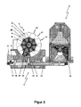
- a workpiece changer 1 is shown for automatic workpiece or pallet change.
- the workpiece changer 1 is constructed in the illustrated embodiment in gantry design and arranged laterally on a machining center 2 to allow lateral loading and unloading of the machining center 2.
- the machining center 2 can be designed in gantry or traveling column construction.
- the workpiece changer 1 has a memory arrangement 3 for workpieces 4 or workpiece pallets 5 with a multiplicity of depositing places 21, which are arranged on a plurality of vertically stacked depositing planes 6, 7 and form the shape of a circular ring.
- the storage spaces 21 are on all storage levels 6, 7 together power-driven about a vertical axis 8 rotatable.
- the workpiece changer 1 furthermore has a handling device 9 for the workpieces 4 or the workpiece pallets 5 located laterally next to the storage arrangement 3.
- the handling device 9 is linearly displaceable along a horizontal axis 10 and linearly along a vertical axis 11 and can additionally be rotated about this vertical axis 11.
- the handling device 9 is moved by means of a drive motor 13 along a bridge 14, which forms the horizontal axis 10.
- the handling device 9 is mounted on a vertical slide 15, which is movable by means of a drive motor 20 in the vertical direction.
- the workpiece changer 1 is mounted on a base frame 12, are arranged on the vertically extending supports 18 which carry the bridge 14. On the base frame 12, a set-up table 17 and a table 19 are further arranged.
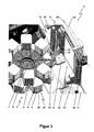
- the storage spaces 21 on a storage level 6, 7 are angularly offset from the storage places 21 on the above and / or underlying storage level 6, 7, so that above and / or below each workpiece 4 or each workpiece pallet 5, a free space is formed in the interference contours 16 of the handling device 9 can immerse in a change process.
- the free space next to each storage space 21 is large enough to supply the workpieces 4 or workpiece pallets 5 with the handling device 9 within the respective storage A, B in the horizontal direction only by a circular or elliptical movement of the respective transfer position 24 or to remove it ,
- the free space next to each storage space 21 is large enough to supply the workpieces 4 or workpiece pallets 5 within the respective storage A, B in the horizontal direction only by the pure circular rotary motion c of the handling device 9 of the respective transfer position 24 or from this to remove.
- One of the storage locations 21 serves as empty space 22 and is not occupied by workpieces 4 or workpiece pallets 5. This makes it possible to transport a workpiece 4 or a workpiece pallet 5 in a linear horizontal direction within the respective storage shelves A, B.
- the empty space 22 is preferably located on the uppermost or the lowest storage level 6, 7.
- each 8 storage spaces 21 are arranged with a uniform circular pitch of 45 °, and the offset between the storage spaces 21 on the vertically adjacent storage levels 6, 7 is 22.5 ° each.
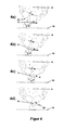
- the automatic loading and unloading of a storage space 21 with the workpiece changer 1 is such that one or more axis movements b, c the handling device 9 and a rotational movement of the memory arrangement 3 are superimposed executed.
- the interference contours 16 of the handling device 9 can dip into the free space between the workpieces 4 or the workpiece pallets 5, which allows a more compact design.
- the automatic loading and unloading of a storage space 21 with the workpiece changer 1 also take place such that the transfer position 24 is approached in a horizontal direction on an elliptical path by the rotational movement c of the handling device 9 performed interpolating with the linear horizontal movement b of the handling device 9 and / or at the same time the rotational movement a of the memory device 3 is performed in order to store larger workpieces 4 or 5 workpiece pallets can.
- the process is complete when the workpiece pallet 5 to be removed has reached the transfer station 24 (see FIG. FIGS. 4a to 4d ).
- the workpiece pallet 5 is received by a gripper device over a short vertical linear movement upwards and removed from the fixation of the storage space 21.
- FIGS. 5a to 5d show a change process within the lower storage level 6 by a pure rotational movement c of the handling device 9. It is also conceivable that the change process is performed by superimposing the movements c and b or c and a or c, b, and a to one less To be able to drive away wide interfering track and thus be able to deposit larger workpieces.
Landscapes
- Engineering & Computer Science (AREA)
- Mechanical Engineering (AREA)
- Feeding Of Workpieces (AREA)
Abstract
Die vorliegende Erfindung betrifft einen Werkstückwechsler (1) für den automatischen Werkstück- oder Palettenwechsel, wobei der Werkstückwechsler (1) vorzugsweise in Portalbauweise aufgebaut und insbesondere zur seitlichen Be- und Entladung eines Bearbeitungszentrums (2) in Gantry- oder Fahrständerbauweise geeignet ist, umfassend eine Speicheranordnung (3) für Werkstücke (4) oder Werkstückpaletten (5) mit einer Vielzahl von Ablageplätzen (21), die auf mehreren vertikal übereinander angeordneten Ablageebenen (6, 7) die Form eines Kreisrings bilden und die auf allen Ablageebenen (6, 7) gemeinsam kraftbetrieben um eine vertikale Achse (8) drehbar sind und eine seitlich neben der Speicheranordnung (3) befindliche Handhabungseinrichtung (9) für die Werkstücke (4) oder die Werkstückpaletten (5), die linear entlang einer horizontalen Achse (10) und linear entlang einer vertikalen Achse (11) verfahrbar und um diese vertikale Achse (11) drehbar ist, bei dem erfindungsgemäß die Ablageplätze (21) auf einer Ablageebene (6, 7) winkelversetzt zu den Ablageplätzen (21) auf der darüber- und/oder darunterliegenden Ablageebene (6, 7) angeordnet sind, so dass über und/oder unter jedem Werkstück (4) bzw. jeder Werkstückpalette (5) ein freier Zwischenraum entsteht, in den die Störkonturen (16) der Handhabungseinrichtung (9) bei einem Wechselvorgang eintauchen können, und dass der freie Zwischenraum neben jedem Ablageplatz (21) groß genug ist, um die Werkstücke (4) oder die Werkstückpaletten (5) mit der Handhabungseinrichtung (9) innerhalb der jeweiligen Ablageetage (A, B) in horizontaler Richtung nur durch eine kreis- oder ellipsenförmige Bewegung der jeweiligen Übergabeposition (24) zuzuführen oder von dieser zu entfernen.The present invention relates to a workpiece changer (1) for the automatic workpiece or pallet change, wherein the workpiece changer (1) preferably constructed in gantry design and in particular for lateral loading and unloading of a machining center (2) in gantry or traveling column construction is suitable, comprising a Storage arrangement (3) for workpieces (4) or workpiece pallets (5) with a plurality of depositing places (21) which form the shape of a circular ring on a plurality of vertically stacked depositing planes (6, 7) and which are arranged on all depositing planes (6, 7). together are rotatable about a vertical axis (8) and a laterally next to the memory arrangement (3) located handling means (9) for the workpieces (4) or the workpiece pallets (5) along a horizontal axis (10) and linear along a vertical axis (11) movable and about this vertical axis (11) is rotatable, in accordance with the invention, the Ab Positioning (21) on a storage plane (6, 7) angularly offset from the storage spaces (21) on the above and / or underlying storage level (6, 7) are arranged so that above and / or below each workpiece (4) or each workpiece pallet (5) creates a free space into which the Störkonturen (16) of the handling device (9) can dive in a change process, and that the free space next to each storage space (21) is large enough to the workpieces (4) or the workpiece pallets (5) with the handling device (9) within the respective storage tray (A, B) in the horizontal direction only by a circular or elliptical movement of the respective transfer position (24) supply or remove it.
Description
Die Erfindung betrifft einen Werkstückwechsler für den automatischen Werkstück- oder Palettenwechsel, wobei der Werkstückwechsler vorzugsweise in Portalbauweise aufgebaut und insbesondere zur seitlichen Be- und Entladung eines Bearbeitungszentrums in Gantry- oder Fahrständerbauweise geeignet ist, umfassend eine Speicheranordnung für Werkstücke oder Werkstückpaletten mit einer Vielzahl von Ablageplätzen, die auf mehreren vertikal übereinander angeordneten Ablageebenen die Form eines Kreisrings bilden und die auf allen Ablageebenen gemeinsam kraftbetrieben um eine vertikale Achse drehbar sind und eine seitlich neben der Speicheranordnung befindliche Handhabungseinrichtung für die Werkstücke oder die Werkstückpaletten, die linear entlang einer horizontalen Achse und linear entlang einer vertikalen Achse verfahrbar und um diese vertikale Achse drehbar ist.The invention relates to a workpiece changer for the automatic workpiece or pallet change, wherein the workpiece changer is preferably constructed in gantry design and is particularly suitable for lateral loading and unloading a machining center in gantry or traveling column design, comprising a memory arrangement for workpieces or workpiece pallets with a variety of storage spaces which form the shape of a circular ring on a plurality of storage levels arranged vertically one above the other and which are jointly rotatable on all depositing planes around a vertical axis and a handling device for the workpieces or the workpiece pallets arranged laterally next to the storage arrangement, which is linear along a horizontal axis and linear along a vertical axis movable and is rotatable about this vertical axis.
Derartige Werkstückwechsler sind aus der
Unter dem Begriff - Portalbauweise - wird im Sinne der vorliegenden Erfindung ein Werkstückwechsler verstanden, der in seiner Ausgestaltung nach dem im Maschinenbau bekannten Portalsystem errichtet ist und beispielsweise einem Portalkran ähnelt, indem eine horizontale Brücke auf vertikalen Stützen angeordnet ist und daran eine hängende, in mehreren Raumrichtungen verfahrbare Handhabungseinrichtung angebracht ist.The term - gantry design - is understood in the context of the present invention, a workpiece changer, which is constructed in its design according to the known in mechanical portal system and, for example, a gantry crane resembles a horizontal bridge is arranged on vertical supports and a hanging, in several Spaces movable handling device is attached.
Zur Automatisierung von Bearbeitungszentren sind zahlreiche Lösungen in Form von Werkstückwechslern, Palettenwechslern oder komplexen Robotersystemen bekannt. Allen gemeinsam ist das Ziel, einen möglichst mannarmen Betrieb eines solchen Bearbeitungszentrums zu ermöglichen, indem eine Vielzahl von unbearbeiteten Rohteilen oder bearbeiteten Fertigteilen in einer Speicheranordnung zwischengelagert und bei Bedarf dem Bearbeitungszentrum automatisch zu- und abgeführt werden. Neben der Bearbeitungsdauer eines Werkstückes bestimmt die Anzahl der Ablageplätze daher maßgeblich die Dauer einer mannlosen Periode und folglich die in einem Betrieb mit mehreren solcher automatisierter Bearbeitungszentren benötigte Anzahl an Bedienern. Dementsprechend ist eine hohe Anzahl von Ablageplätzen in den meisten Fällen von großem Vorteil. Um auf kleiner Aufstellfläche eine hohe Speicherkapazität zu erreichen, eignen sich Speichereinheiten mit mehreren Ablageebenen besonders gut. Jedoch bestehen auch in der Höhe gewisse Platzbeschränkungen, so dass es nutzbringend ist, die einzelnen Ablageebenen unter Berücksichtigung der maximalen Werkstückhöhe möglichst dicht übereinander anzuordnen. Dabei muss allerdings berücksichtigt werden, dass die Werkstücke inklusive der eventuell vorhandenen Werkstückpaletten trotz der dichten Anordnung noch möglichst einfach aus den Ablageplätzen entnommen werden können, ohne hierfür eine zusätzliche Fahrachse oder gar eine zusätzliche Wechseleinrichtung vorsehen zu müssen. Weiterhin gilt es für einen Werkstückwechsler der eingangs genannten Art zu berücksichtigen, dass der Arbeitsraum des Bearbeitungszentrums für eventuelle manuelle Eingriffe eine gute Zugänglichkeit aufweisen sollte.Numerous solutions in the form of workpiece changers, pallet changers or complex robot systems are known for the automation of machining centers. All have in common is the goal to enable a low-manpower as possible operation of such a machining center by a variety of unprocessed blanks or machined finished parts stored in a storage arrangement and automatically fed to the processing center and removed. In addition to the processing time of a workpiece, therefore, the number of storage spaces significantly determines the duration of a unmanned period and consequently in an operation with several such automated machining centers needed number of operators. Accordingly, a high number of storage spaces in most cases of great advantage. In order to achieve a high storage capacity on a small footprint, storage units with several storage levels are particularly well suited. However, there are also some space restrictions in the height, so that it is useful to arrange the individual storage levels as closely as possible, taking into account the maximum workpiece height. However, it must be taken into account that, in spite of the tight arrangement, the workpieces, including any workpiece pallets, can still be removed as easily as possible from the depositing places without having to provide an additional driving axle or even an additional changing device. Furthermore, it should be considered for a workpiece changer of the type mentioned that the working space of the machining center for any manual intervention should have good accessibility.
Aus der
Aus der
Ausgehend vom Stand der Technik liegt der vorliegenden Erfindung die Aufgabe zugrunde, einen Werkstückwechsler mit einer mehrstöckigen Speicheranordnung zu schaffen, die es insbesondere für ein Portalsystem ermöglicht, mit einer Handhabungseinrichtung, die nur zwei translatorische und eine rotatorische Bewegungsrichtung ausführen kann, sowohl die Werkstücke bzw. die Werkstückpaletten aus der Speicheranordnung zu entnehmen und abzulegen, als auch den Werkstückwechsel mit dem Bearbeitungszentrum, vorzugsweise von der Seite, durchzuführen. Außerdem soll der Werkstückwechsler möglichst platzsparend aufgebaut sein und gegenüber einem Werkstückwechsler mit einer gleichartig aufgebauten einstöckigen Speicheranordnung keine maßgebliche Vergrößerung der Aufstellfläche verursachen.Based on the prior art, the present invention seeks to provide a workpiece changer with a multi-storey memory arrangement, which makes it possible in particular for a gantry system, with a handling device that can perform only two translational and a rotational direction of movement, both the workpieces or to remove the workpiece pallets from the storage arrangement and store, as well as the workpiece change with the machining center, preferably from the side to perform. In addition, the workpiece changer should be constructed as space-saving and cause no significant increase in the footprint compared to a workpiece changer with a similarly constructed single-level memory array.
Diese Aufgabe wird bei einem Werkstückwechsler für den automatischen Werkstück- oder Palettenwechsel, wobei der Werkstückwechsler vorzugsweise in Portalbauweise aufgebaut und insbesondere zur seitlichen Be- und Entladung eines Bearbeitungszentrums in Gantry- oder Fahrständerbauweise geeignet ist, umfassend eine Speicheranordnung für Werkstücke oder Werkstückpaletten mit einer Vielzahl von Ablageplätzen, die auf mehreren vertikal übereinander angeordneten Ablageebenen die Form eines Kreisrings bilden und die auf allen Ablageebenen gemeinsam kraftbetrieben um eine vertikale Achse drehbar sind und eine seitlich neben der Speicheranordnung befindliche Handhabungseinrichtung für die Werkstücke oder die Werkstückpaletten, die linear entlang einer horizontalen Achse und linear entlang einer vertikalen Achse verfahrbar und um diese vertikale Achse drehbar ist, erfindungsgemäß dadurch gelöst, dass die Ablageplätze auf einer Ablageebene winkelversetzt zu den Ablageplätzen auf der darüber- und/oder darunterliegenden Ablageebene angeordnet sind, so dass über und/oder unter jedem Werkstück bzw. jeder Werkstückpalette ein freier Zwischenraum entsteht, in den die Störkonturen der Handhabungseinrichtung bei einem Wechselvorgang eintauchen können, und dass der freie Zwischenraum neben jedem Ablageplatz groß genug ist, um die Werkstücke oder die Werkstückpaletten mit der Handhabungseinrichtung in der jeweiligen Ablageetage in horizontaler Richtung nur durch eine kreis- oder ellipsenförmige Bewegung der jeweiligen Übergabeposition zuzuführen oder von dieser zu entfernen.This object is in a workpiece changer for automatic workpiece or pallet change, the workpiece changer is preferably constructed in gantry design and is particularly suitable for lateral loading and unloading a machining center in gantry or traveling column design, comprising a memory arrangement for workpieces or workpiece pallets with a variety of Storage spaces, which form the shape of a circular ring on a plurality of vertically stacked storage levels and the on all storage levels together are power-driven rotatable about a vertical axis and located laterally next to the storage arrangement handling device for the workpieces or workpiece pallets, which is linear along a horizontal axis and linear along a vertical axis movable and rotatable about this vertical axis, according to the invention thereby solved in that the depositing places are arranged at a depositing plane offset in angle from the depositing places on the depositing plane above and / or below, so that above and / or below each workpiece or each workpiece pallet a free interspace arises in which the interfering contours of the handling device occur during a changing operation can dive, and that the free space next to each storage space is large enough to the workpieces or workpiece pallets with the handling device in the respective storage tray in the horizontal direction only by a circular or elliptical e Move the movement to the respective transfer position or remove it from it.
Die Erfindung verbessert den bekannten Stand der Technik dahingehend, dass es erstmalig möglich ist, eine Handhabungseinrichtung so nahe neben einer mehrstöckigen kreisringförmigen Speicheranordnung anzuordnen, dass sich der Störkreis der Speicheranordnung mit Störkonturen der Handhabungseinrichtung in gewissen Ebenen überschneidet. Mehrstöckige Speicheranordnungen, bei denen die Handhabungseinrichtung aus Platzgründen derart nahe neben der Speicheranordnung angebracht ist, mussten bisher mit großem vertikalem Abstand zwischen den Ablageebenen ausgeführt werden, damit die Störkonturen nicht kollidieren und ein Wechselvorgang durch eine Drehbewegung im vertikalen Zwischenraum erfolgen konnte. Nach dem neuen erfindungsgemäßen Aufbau kann der vertikale Abstand zwischen der Werkstückoberkante und der darüber liegenden Ablageebene sehr klein gehalten werden, so dass der vertikale Abstand zwischen zwei Ablageebenen gegenüber dem bekannten Stand der Technik nahezu halbiert wird.The invention improves on the known state of the art in that for the first time it is possible to arrange a handling device so close to a multi-storey circular-shaped memory arrangement that the interference circuit of the memory arrangement intersects with interference contours of the handling device at certain levels. Multi-storey storage arrangements in which the handling device is mounted for reasons of space so close to the storage arrangement, previously had to be performed with a large vertical distance between the storage levels, so that the interfering contours could not collide and a change operation could be done by a rotary motion in the vertical space. According to the novel structure according to the invention, the vertical distance between the workpiece top edge and the overlying storage level can be kept very small, so that the vertical distance between two storage levels compared to the known prior art is almost halved.
Die Speicherkapazität des Werkstückwechslers wird durch den Aufbau mit mehreren Ablageebenen gegenüber einem Werkstückwechsler mit einer gleichartig aufgebauten einstöckigen Speicheranordnung um ein Vielfaches erhöht, ohne die Aufstellfläche maßgeblich zu vergrößern. Für die Ausführung mit nur zwei Ablageebenen wird die Speicherkapazität verdoppelt, obwohl die Gesamthöhe des Werkstückwechslers gegenüber einer einstöckigen Variante nicht erhöht werden muss. Nach dem bisherigen Stand der Technik musste der Wechselvorgang nämlich über der jeweiligen Ablageetage erfolgen, wenn die Handhabungseinrichtung derart nahe neben der Speicheranordnung angebracht war. Ein Werkstückwechsler mit einstöckiger Speicheranordnung musste daher bereits gleich hoch ausgeführt sein, wie es bei einer zweistöckigen Ausführung nach dem neuen erfindungsgemäßen Aufbau, der einen Wechselvorgang innerhalb der gleichen Ablageetage zulässt, der Fall ist.The storage capacity of the workpiece changer is due to the structure with multiple storage levels compared to a workpiece changer with a similarly constructed single-storey memory array many times increased without significantly increasing the footprint. For the design with only two storage levels, the storage capacity is doubled, although the total height of the workpiece changer does not have to be increased compared to a single-storey variant. Namely, according to the prior art, when the handling device was so close to the storage device, the changing operation had to be performed over the respective storage tray. A workpiece changer with single-storey storage arrangement therefore had to be designed to be the same height as is the case in a two-storey design according to the novel construction according to the invention, which permits a change operation within the same storage floor.
Die Unteransprüche haben vorteilhafte Weiterbildungen der Erfindung zum Inhalt.The dependent claims have advantageous developments of the invention to the content.
Gemäß einer bevorzugten Weiterbildung ist der freie Zwischenraum neben jedem Ablageplatz groß genug, um die Werkstücke oder die Werkstückpaletten innerhalb der jeweiligen Ablageetage in horizontaler Richtung nur durch die reine kreisförmige Drehbewegung der Handhabungseinrichtung der jeweiligen Übergabeposition zuzuführen oder von dieser zu entfernen.According to a preferred embodiment of the free space next to each storage space is large enough to supply the workpieces or the workpiece pallets within the respective storage level in the horizontal direction only by the pure circular rotary motion of the handling device of the respective transfer position or remove it.
Gemäß einer bevorzugten Weiterbildung dient ein Ablageplatz als Leerplatz und wird nicht mit Werkstücken bzw. Werkstückpaletten belegt, um den Transport eines Werkstücks bzw. einer Werkstückpalette in linearer Horizontalrichtung innerhalb der jeweiligen Ablageetage zu ermöglichen.According to a preferred embodiment, a storage space serves as an empty space and is not occupied with workpieces or workpiece pallets to allow the transport of a workpiece or a workpiece pallet in a linear horizontal direction within the respective storage floor.
Gemäß einer bevorzugten Weiterbildung befindet sich der Leerplatz auf der obersten oder der untersten Ablageebene.According to a preferred embodiment, the empty space is located on the topmost or the lowest storage level.
Gemäß einer bevorzugten Weiterbildung sind pro Ablageebene jeweils 8 Ablageplätze mit einer gleichmäßigen Kreisteilung von 45° angeordnet.According to a preferred development, 8 storage spaces with a uniform circular graduation of 45 ° are arranged per storage level.
Gemäß einer bevorzugten Weiterbildung beträgt der Versatz zwischen den Ablageplätzen auf den vertikal benachbarten Ablageebenen jeweils 22,5°.According to a preferred refinement, the offset between the depositing places on the vertically adjacent depositing planes is 22.5 ° in each case.
Der Erfindung liegt ferner die Aufgabe zugrunde, ein Verfahren für den automatischen Wechselvorgang bereitzustellen, durch das die vorgegebenen Platzverhältnisse optimal genutzt werden können und eine kompaktere Bauweise ermöglicht werden kann.The invention is further based on the object to provide a method for the automatic changing process by which the given space can be used optimally and a more compact design can be made possible.
Diese Aufgabe wird gelöst durch ein Verfahren zum automatischen Be- und Entladen eines Ablageplatzes des Werkstückwechslers, bei dem eine oder mehrere Achsbewegungen der Handhabungseinrichtung und eine Drehbewegung der Speicheranordnung überlagert ausgeführt werden, um mit den Störkonturen der Handhabungseinrichtung in den freien Zwischenraum zwischen den Werkstücken bzw. den Werkstückpaletten eintauchen zu können. Dies ermöglicht eine kompaktere Bauweise.This object is achieved by a method for automatically loading and unloading a storage space of the workpiece changer, in which one or more axis movements of the handling device and a rotational movement of the storage arrangement are executed superimposed to interact with the interfering contours of the handling device in the free space between the workpieces or be able to immerse the workpiece pallets. This allows a more compact design.
Diese Aufgabe wird außerdem gelöst durch ein Verfahren zum automatischen Be- und Entladen eines Ablageplatzes des Werkstückwechslers, bei dem die Übergabeposition in horizontaler Richtung auf einer ellipsenförmigen Bahn angefahren wird, indem eine Drehbewegung der Handhabungseinrichtung interpolierend mit einer linearen Horizontalbewegung der Handhabungseinrichtung ausgeführt wird und/oder gleichzeitig die Drehbewegung der Speicheranordnung ausgeführt wird, um größere Werkstücke bzw. Werkstückpaletten ablegen zu können.This object is also achieved by a method for automatically loading and unloading a storage space of the workpiece changer, in which the transfer position in the horizontal direction is approached on an elliptical path by a rotational movement of the handling device is performed interpolating with a linear horizontal movement of the handling device and / or at the same time the rotational movement of the storage arrangement is carried out in order to store larger workpieces or workpiece pallets can.
Weitere Einzelheiten, Merkmale und Vorteile der Erfindung ergeben sich aus nachfolgender Beschreibung anhand der Zeichnungen. Es zeigen:
Figur 1- eine Seitenansicht eines erfindungsgemäß aufgebauten Werkstückwechslers,
Figur 2- eine Draufsicht auf einen erfindungsgemäß aufgebauten Werkstückwechsler,
Figur 3- eine Detailansicht des erfindungsgemäß aufgebauten Werkstückwechslers,
Figur 4- den Werkstückwechselvorgang (Annäherung der Handhabungseinrichtung zur Werkstückpalette), und
Figur 5- den Werkstückwechselvorgang in der unteren Ablageebene.
- FIG. 1
- a side view of an inventively constructed workpiece changer,
- FIG. 2
- a top view of a inventively constructed workpiece changer,
- FIG. 3
- a detailed view of the inventively constructed workpiece changer,
- FIG. 4
- the workpiece change operation (approach of the handling device to the workpiece pallet), and
- FIG. 5
- the workpiece change process in the lower storage level.
In den
Der Werkstückwechsler 1 weist eine Speicheranordnung 3 für Werkstücke 4 oder Werkstückpaletten 5 mit einer Vielzahl von Ablageplätzen 21 auf, die auf mehreren vertikal übereinander angeordneten Ablageebenen 6, 7 angeordnet sind und die Form eines Kreisrings bilden. Die Ablageplätze 21 sind auf allen Ablageebenen 6, 7 gemeinsam kraftbetrieben um eine vertikale Achse 8 drehbar.The
Der Werkstückwechsler 1 weist weiterhin eine seitlich neben der Speicheranordnung 3 befindliche Handhabungseinrichtung 9 für die Werkstücke 4 oder die Werkstückpaletten 5 auf. Die Handhabungseinrichtung 9 ist linear entlang einer horizontalen Achse 10 und linear entlang einer vertikalen Achse 11 verfahrbar und kann zusätzlich um diese vertikale Achse 11 gedreht werden. Zur horizontalen Verfahrbarkeit ist die Handhabungseinrichtung 9 mittels eines Antriebsmotors 13 entlang einer Brücke 14 verfahrbar, welche die horizontale Achse 10 bildet. Zur vertikalen Verfahrbarkeit ist die Handhabungseinrichtung 9 an einem Vertikalschlitten 15 gelagert, der mittels eines Antriebsmotors 20 in vertikaler Richtung verfahrbar ist.The
Der Werkstückwechsler 1 ist auf einem Grundgestell 12 gelagert, auf dem vertikal verlaufenden Stützen 18 angeordnet sind, welche die Brücke 14 tragen. Auf dem Grundgestell 12 sind weiterhin ein Rüsttisch 17 und ein Tisch 19 angeordnet.The
Die Ablageplätze 21 auf einer Ablageebene 6, 7 sind winkelversetzt zu den Ablageplätzen 21 auf der darüber- und/oder darunterliegenden Ablageebene 6, 7 angeordnet, so dass über und/oder unter jedem Werkstück 4 bzw. jeder Werkstückpalette 5 ein freier Zwischenraum entsteht, in den die Störkonturen 16 der Handhabungseinrichtung 9 bei einem Wechselvorgang eintauchen können. Der freie Zwischenraum neben jedem Ablageplatz 21 ist groß genug, um die Werkstücke 4 oder Werkstückpaletten 5 mit der Handhabungseinrichtung 9 innerhalb der jeweiligen Ablageetage A, B in horizontaler Richtung nur durch eine kreis- oder ellipsenförmige Bewegung der jeweiligen Übergabeposition 24 zuzuführen oder von dieser zu entfernen.The
Bei dem dargestellten Ausführungsbeispiel ist der freie Zwischenraum neben jedem Ablageplatz 21 groß genug, um die Werkstücke 4 oder Werkstückpaletten 5 innerhalb der jeweiligen Ablageetage A, B in horizontaler Richtung nur durch die reine kreisförmige Drehbewegung c der Handhabungseinrichtung 9 der jeweiligen Übergabeposition 24 zuzuführen oder von dieser zu entfernen.In the illustrated embodiment, the free space next to each
Einer der Ablageplätze 21 dient als Leerplatz 22 und wird nicht mit Werkstücken 4 bzw. Werkstückpaletten 5 belegt. Dies ermöglicht den Transport eines Werkstücks 4 bzw. einer Werkstückpalette 5 in linearer Horizontalrichtung innerhalb der jeweiligen Ablageetage A, B.One of the
Der Leerplatz 22 befindet sich bevorzugt auf der obersten oder der untersten Ablageebene 6, 7.The
Pro Ablageebene 6, 7 sind jeweils 8 Ablageplätze 21 mit einer gleichmäßigen Kreisteilung von 45° angeordnet, und der Versatz zwischen den Ablageplätzen 21 auf den vertikal benachbarten Ablageebenen 6, 7 beträgt jeweils 22,5°.Per
Das automatische Be- und Entladen eines Ablageplatzes 21 mit dem Werkstückwechsler 1 erfolgt derart, dass eine oder mehrere Achsbewegungen b, c der Handhabungseinrichtung 9 und eine Drehbewegung a der Speicheranordnung 3 überlagert ausgeführt werden. Somit können die Störkonturen 16 der Handhabungseinrichtung 9 in den freien Zwischenraum zwischen den Werkstücken 4 bzw. den Werkstückpaletten 5 eintauchen, was eine kompaktere Bauweise ermöglicht.The automatic loading and unloading of a
Zusätzlich kann das automatische Be- und Entladen eines Ablageplatzes 21 mit dem Werkstückwechsler 1 auch derart erfolgen, dass die Übergabeposition 24 in horizontaler Richtung auf einer ellipsenförmigen Bahn angefahren wird, indem die Drehbewegung c der Handhabungseinrichtung 9 interpolierend mit der linearen Horizontalbewegung b der Handhabungseinrichtung 9 ausgeführt wird und/oder gleichzeitig die Drehbewegung a der Speicheranordnung 3 ausgeführt wird, um größere Werkstücke 4 bzw. Werkstückpaletten 5 ablegen zu können.In addition, the automatic loading and unloading of a
Vor einem Wechsel wird die aus der Speicheranordnung 3 zu entnehmende Werkstückpalette 5 durch eine Drehung der Speicheranordnung 3 in eine Vorposition 23 gebracht. Dafür ist es erforderlich, dass die Störkonturen 16 der Handhabungseinrichtung 9 über der Oberkante der in der oberen Ablageetage 7 abgelegten Werkstücke 4 positioniert sind. Anschließend bewegt sich die Handhabungseinrichtung 9 in vertikaler Richtung nach unten. Bei der Entnahme einer Werkstückpalette 5 von der unteren Ablageebene 6 tauchen die Störkonturen 16 der Handhabungseinrichtung 9 dabei in den freien Zwischenraum zwischen den Werkstücken 4 aus der oberen Ablageebene 7 ein. Daraufhin wird die Handhabungseinrichtung 9 durch folgende simultane Bewegungen an den Palettenhalter 25 angenähert:
- Drehbewegung a
der Speicheranordnung 3 - Horizontalbewegung
b der Handhabungseinrichtung 9 - Drehbewegung c der Handhabungseinrichtung 9
- Rotational movement a of the
memory arrangement 3 - Horizontal movement b of the
handling device 9 - Rotational movement c of the
handling device 9
Der Vorgang ist abgeschlossen, wenn die zu entnehmende Werkstückpalette 5 den Übergabeplatz 24 erreicht hat (s.
Abschließend wird die Werkstückpalette 5 über eine kurze vertikale Linearbewegung nach oben durch eine Greifervorrichtung aufgenommen und aus der Fixierung des Ablageplatzes 21 entnommen.Finally, the
Die
Die vorhergehende Beschreibung der vorliegenden Erfindung dient nur zu illustrativen Zwecken und nicht zum Zwecke der Beschränkung der Erfindung. Im Rahmen der Erfindung sind verschiedene Änderungen und Modifikationen möglich, ohne den Umfang der Erfindung sowie ihrer Äquivalente zu verlassen.The foregoing description of the present invention is for illustrative purposes only, and not for the purpose of limiting the invention. Various changes and modifications are possible within the scope of the invention without departing from the scope of the invention and its equivalents.
- 11
- WerkstückwechslerWorkpiece changer
- 22
- Bearbeitungszentrummachining center
- 33
- Speicheranordnungmemory array
- 44
- Werkstückworkpiece
- 55
- WerkstückpaletteWorkpiece pallet
- 66
- Ablageebenestorage level
- 77
- Ablageebenestorage level
- 88th
- Vertikale AchseVertical axis
- 99
- Handhabungseinrichtunghandling device
- 1010
- Horizontale AchseHorizontal axis
- 1111
- Vertikale AchseVertical axis
- 1212
- Grundgestellbase frame
- 1313
- Antriebsmotordrive motor
- 1414
- Brückebridge
- 1515
- Vertikalschlittenvertical slide
- 1616
- Störkontureninterfering contours
- 1717
- Rüsttischset-up table
- 1818
- Stützesupport
- 1919
- Tischtable
- 2020
- Antriebsmotordrive motor
- 2121
- Ablageplatzspace
- 2222
- Leerplatzempty space
- 2323
- Vorpositionpre-position
- 2424
- ÜbergabepositionTransfer position
- 2525
- Palettenhalterpallet holder
- AA
- Ablageetagestorage floor
- BB
- Ablageetagestorage floor
- aa
- Drehbewegung SpeicheranordnungRotary movement storage arrangement
- bb
- Horizontalbewegung HandhabungseinrichtungHorizontal movement handling device
- cc
- Drehbewegung HandhabungseinrichtungRotary movement handling device
Claims (8)
dadurch gekennzeichnet, dass die Ablageplätze (21) auf einer Ablageebene (6, 7) winkelversetzt zu den Ablageplätzen (21) auf der darüber- und/oder darunterliegenden Ablageebene (6, 7) angeordnet sind, so dass über und/oder unter jedem Werkstück (4) bzw. jeder Werkstückpalette (5) ein freier Zwischenraum entsteht, in den die Störkonturen (16) der Handhabungseinrichtung (9) bei einem Wechselvorgang eintauchen können, und dass der freie Zwischenraum neben jedem Ablageplatz (21) groß genug ist, um die Werkstücke (4) oder die Werkstückpaletten (5) mit der Handhabungseinrichtung (9) innerhalb der jeweiligen Ablageetage (A, B) in horizontaler Richtung nur durch eine kreis- oder ellipsenförmige Bewegung der jeweiligen Übergabeposition (24) zuzuführen oder von dieser zu entfernen.
characterized in that the storage places (21) on a storage plane (6, 7) angularly offset from the storage places (21) on the above and / or underlying storage level (6, 7) are arranged so that above and / or below each workpiece (4) or each workpiece pallet (5) creates a free space into which the Störkonturen (16) of the handling device (9) can dive in a change process, and that the free space next to each storage space (21) is large enough to the Workpieces (4) or the workpiece pallets (5) with the handling device (9) within the respective storage floor (A, B) in the horizontal direction only by a circular or elliptical movement of the respective transfer position (24) supply or remove it.
Priority Applications (1)
| Application Number | Priority Date | Filing Date | Title |
|---|---|---|---|
| EP13003718.7A EP2829358B1 (en) | 2013-07-24 | 2013-07-24 | Workpiece changing device for automatic work piece or pallet changing in a processing centre |
Applications Claiming Priority (1)
| Application Number | Priority Date | Filing Date | Title |
|---|---|---|---|
| EP13003718.7A EP2829358B1 (en) | 2013-07-24 | 2013-07-24 | Workpiece changing device for automatic work piece or pallet changing in a processing centre |
Publications (2)
| Publication Number | Publication Date |
|---|---|
| EP2829358A1 true EP2829358A1 (en) | 2015-01-28 |
| EP2829358B1 EP2829358B1 (en) | 2016-09-21 |
Family
ID=48915792
Family Applications (1)
| Application Number | Title | Priority Date | Filing Date |
|---|---|---|---|
| EP13003718.7A Active EP2829358B1 (en) | 2013-07-24 | 2013-07-24 | Workpiece changing device for automatic work piece or pallet changing in a processing centre |
Country Status (1)
| Country | Link |
|---|---|
| EP (1) | EP2829358B1 (en) |
Cited By (2)
| Publication number | Priority date | Publication date | Assignee | Title |
|---|---|---|---|---|
| DE102020115816A1 (en) | 2020-06-16 | 2021-12-16 | Liebherr-Verzahntechnik Gmbh | Storage and / or manufacturing system with at least one handling device |
| EP4163053A1 (en) * | 2021-10-06 | 2023-04-12 | WFL Millturn Technologies GmbH & Co. KG | Flexible manufacturing cell |
Citations (4)
| Publication number | Priority date | Publication date | Assignee | Title |
|---|---|---|---|---|
| US4986715A (en) * | 1988-07-13 | 1991-01-22 | Tokyo Electron Limited | Stock unit for storing carriers |
| EP0462533A2 (en) | 1990-06-20 | 1991-12-27 | Matsuura Machinery Corporation | Pallet storage device and pallet exchange device for machine tool, and lathe with pallet automatically removable |
| US20040245278A1 (en) * | 2003-01-30 | 2004-12-09 | Steffens Lowell G. | Propane tank vending machine |
| DE102011016713A1 (en) | 2011-04-11 | 2012-10-11 | Liebherr-Verzahntechnik Gmbh | manufacturing system |
-
2013
- 2013-07-24 EP EP13003718.7A patent/EP2829358B1/en active Active
Patent Citations (5)
| Publication number | Priority date | Publication date | Assignee | Title |
|---|---|---|---|---|
| US4986715A (en) * | 1988-07-13 | 1991-01-22 | Tokyo Electron Limited | Stock unit for storing carriers |
| EP0462533A2 (en) | 1990-06-20 | 1991-12-27 | Matsuura Machinery Corporation | Pallet storage device and pallet exchange device for machine tool, and lathe with pallet automatically removable |
| US20040245278A1 (en) * | 2003-01-30 | 2004-12-09 | Steffens Lowell G. | Propane tank vending machine |
| DE102011016713A1 (en) | 2011-04-11 | 2012-10-11 | Liebherr-Verzahntechnik Gmbh | manufacturing system |
| EP2511044A2 (en) * | 2011-04-11 | 2012-10-17 | LIEBHERR-VERZAHNTECHNIK GmbH | Manufacturing system |
Cited By (2)
| Publication number | Priority date | Publication date | Assignee | Title |
|---|---|---|---|---|
| DE102020115816A1 (en) | 2020-06-16 | 2021-12-16 | Liebherr-Verzahntechnik Gmbh | Storage and / or manufacturing system with at least one handling device |
| EP4163053A1 (en) * | 2021-10-06 | 2023-04-12 | WFL Millturn Technologies GmbH & Co. KG | Flexible manufacturing cell |
Also Published As
| Publication number | Publication date |
|---|---|
| EP2829358B1 (en) | 2016-09-21 |
Similar Documents
| Publication | Publication Date | Title |
|---|---|---|
| EP2792431B1 (en) | Machining system for structural components of aircraft | |
| EP2812152B1 (en) | Honing machine with a plurality of work stations and a rotary table | |
| EP3579987B1 (en) | Bending tool storage device and method for feeding a press brake | |
| EP0977651B1 (en) | Process and device for manufacturing complex parts | |
| WO1986003153A1 (en) | Flexible manufacturing system for the processing and production of multiple-component assemblies, in particular unfinished coachwork assemblies | |
| DE3823947C2 (en) | ||
| DE102009008647A1 (en) | System for changing and inserting or presenting tools on a machine tool and tool magazine for storing tools | |
| DE102006000721A1 (en) | Handling system e.g. for handling work piece with industrial robot, has robot for moving workpieces from storage zone to processing machine and batch zone is provided | |
| DE102019204612A1 (en) | Manufacturing station for processing components | |
| CH709498B1 (en) | Carousel storage for a processing machine and processing machine with such a carousel storage. | |
| EP1511596B1 (en) | Multi-spindle lathe | |
| EP2829358B1 (en) | Workpiece changing device for automatic work piece or pallet changing in a processing centre | |
| DE202009006856U1 (en) | Transport device for transporting objects from and to a workstation | |
| EP3740344B1 (en) | Machine tool for machining workpieces, and method for changing a pallet in a machine tool | |
| EP0129677A2 (en) | Machining centre for milling and drilling operations | |
| WO2017182015A1 (en) | Method for handling stacked part carriers which receive parts within an automation cell, and automation cell for carrying out the method | |
| DE102016120151A1 (en) | Method and machine tool for processing plate-shaped workpieces, in particular sheets | |
| DE3816861A1 (en) | Flexible production apparatus with several processing machines arranged next to one another in parallel at a distance apart | |
| DE202015101884U1 (en) | Plant for the transport of objects from and to a workstation | |
| EP2918373A1 (en) | Tool storage arrangement for extending the tool storage capacity of a milling, drilling and/or turning centre | |
| DE102021113892B4 (en) | Combined transfer and storage device and machining plant | |
| EP2823933B1 (en) | Tool storage arrangement for extending the tool storage capacity of a milling, drilling and/or turning centre | |
| DE202007018833U1 (en) | machine tool | |
| DE8914604U1 (en) | Handling device | |
| EP2708313A1 (en) | Method and device for automated processing of workpieces in finishing cells |
Legal Events
| Date | Code | Title | Description |
|---|---|---|---|
| 17P | Request for examination filed |
Effective date: 20130724 |
|
| AK | Designated contracting states |
Kind code of ref document: A1 Designated state(s): AL AT BE BG CH CY CZ DE DK EE ES FI FR GB GR HR HU IE IS IT LI LT LU LV MC MK MT NL NO PL PT RO RS SE SI SK SM TR |
|
| AX | Request for extension of the european patent |
Extension state: BA ME |
|
| PUAI | Public reference made under article 153(3) epc to a published international application that has entered the european phase |
Free format text: ORIGINAL CODE: 0009012 |
|
| R17P | Request for examination filed (corrected) |
Effective date: 20150216 |
|
| RBV | Designated contracting states (corrected) |
Designated state(s): AL AT BE BG CH CY CZ DE DK EE ES FI FR GB GR HR HU IE IS IT LI LT LU LV MC MK MT NL NO PL PT RO RS SE SI SK SM TR |
|
| GRAP | Despatch of communication of intention to grant a patent |
Free format text: ORIGINAL CODE: EPIDOSNIGR1 |
|
| INTG | Intention to grant announced |
Effective date: 20160617 |
|
| GRAS | Grant fee paid |
Free format text: ORIGINAL CODE: EPIDOSNIGR3 |
|
| GRAA | (expected) grant |
Free format text: ORIGINAL CODE: 0009210 |
|
| AK | Designated contracting states |
Kind code of ref document: B1 Designated state(s): AL AT BE BG CH CY CZ DE DK EE ES FI FR GB GR HR HU IE IS IT LI LT LU LV MC MK MT NL NO PL PT RO RS SE SI SK SM TR |
|
| REG | Reference to a national code |
Ref country code: GB Ref legal event code: FG4D Free format text: NOT ENGLISH |
|
| REG | Reference to a national code |
Ref country code: CH Ref legal event code: EP |
|
| REG | Reference to a national code |
Ref country code: AT Ref legal event code: REF Ref document number: 830648 Country of ref document: AT Kind code of ref document: T Effective date: 20161015 |
|
| REG | Reference to a national code |
Ref country code: IE Ref legal event code: FG4D Free format text: LANGUAGE OF EP DOCUMENT: GERMAN |
|
| REG | Reference to a national code |
Ref country code: DE Ref legal event code: R096 Ref document number: 502013004639 Country of ref document: DE |
|
| REG | Reference to a national code |
Ref country code: CH Ref legal event code: NV Representative=s name: KELLER AND PARTNER PATENTANWAELTE AG, CH |
|
| REG | Reference to a national code |
Ref country code: LT Ref legal event code: MG4D Ref country code: NL Ref legal event code: MP Effective date: 20160921 |
|
| PG25 | Lapsed in a contracting state [announced via postgrant information from national office to epo] |
Ref country code: NO Free format text: LAPSE BECAUSE OF FAILURE TO SUBMIT A TRANSLATION OF THE DESCRIPTION OR TO PAY THE FEE WITHIN THE PRESCRIBED TIME-LIMIT Effective date: 20161221 Ref country code: FI Free format text: LAPSE BECAUSE OF FAILURE TO SUBMIT A TRANSLATION OF THE DESCRIPTION OR TO PAY THE FEE WITHIN THE PRESCRIBED TIME-LIMIT Effective date: 20160921 Ref country code: LT Free format text: LAPSE BECAUSE OF FAILURE TO SUBMIT A TRANSLATION OF THE DESCRIPTION OR TO PAY THE FEE WITHIN THE PRESCRIBED TIME-LIMIT Effective date: 20160921 Ref country code: RS Free format text: LAPSE BECAUSE OF FAILURE TO SUBMIT A TRANSLATION OF THE DESCRIPTION OR TO PAY THE FEE WITHIN THE PRESCRIBED TIME-LIMIT Effective date: 20160921 |
|
| PG25 | Lapsed in a contracting state [announced via postgrant information from national office to epo] |
Ref country code: GR Free format text: LAPSE BECAUSE OF FAILURE TO SUBMIT A TRANSLATION OF THE DESCRIPTION OR TO PAY THE FEE WITHIN THE PRESCRIBED TIME-LIMIT Effective date: 20161222 Ref country code: SE Free format text: LAPSE BECAUSE OF FAILURE TO SUBMIT A TRANSLATION OF THE DESCRIPTION OR TO PAY THE FEE WITHIN THE PRESCRIBED TIME-LIMIT Effective date: 20160921 Ref country code: LV Free format text: LAPSE BECAUSE OF FAILURE TO SUBMIT A TRANSLATION OF THE DESCRIPTION OR TO PAY THE FEE WITHIN THE PRESCRIBED TIME-LIMIT Effective date: 20160921 Ref country code: NL Free format text: LAPSE BECAUSE OF FAILURE TO SUBMIT A TRANSLATION OF THE DESCRIPTION OR TO PAY THE FEE WITHIN THE PRESCRIBED TIME-LIMIT Effective date: 20160921 |
|
| PG25 | Lapsed in a contracting state [announced via postgrant information from national office to epo] |
Ref country code: EE Free format text: LAPSE BECAUSE OF FAILURE TO SUBMIT A TRANSLATION OF THE DESCRIPTION OR TO PAY THE FEE WITHIN THE PRESCRIBED TIME-LIMIT Effective date: 20160921 Ref country code: RO Free format text: LAPSE BECAUSE OF FAILURE TO SUBMIT A TRANSLATION OF THE DESCRIPTION OR TO PAY THE FEE WITHIN THE PRESCRIBED TIME-LIMIT Effective date: 20160921 |
|
| PG25 | Lapsed in a contracting state [announced via postgrant information from national office to epo] |
Ref country code: SK Free format text: LAPSE BECAUSE OF FAILURE TO SUBMIT A TRANSLATION OF THE DESCRIPTION OR TO PAY THE FEE WITHIN THE PRESCRIBED TIME-LIMIT Effective date: 20160921 Ref country code: PT Free format text: LAPSE BECAUSE OF FAILURE TO SUBMIT A TRANSLATION OF THE DESCRIPTION OR TO PAY THE FEE WITHIN THE PRESCRIBED TIME-LIMIT Effective date: 20170123 Ref country code: ES Free format text: LAPSE BECAUSE OF FAILURE TO SUBMIT A TRANSLATION OF THE DESCRIPTION OR TO PAY THE FEE WITHIN THE PRESCRIBED TIME-LIMIT Effective date: 20160921 Ref country code: PL Free format text: LAPSE BECAUSE OF FAILURE TO SUBMIT A TRANSLATION OF THE DESCRIPTION OR TO PAY THE FEE WITHIN THE PRESCRIBED TIME-LIMIT Effective date: 20160921 Ref country code: SM Free format text: LAPSE BECAUSE OF FAILURE TO SUBMIT A TRANSLATION OF THE DESCRIPTION OR TO PAY THE FEE WITHIN THE PRESCRIBED TIME-LIMIT Effective date: 20160921 Ref country code: BG Free format text: LAPSE BECAUSE OF FAILURE TO SUBMIT A TRANSLATION OF THE DESCRIPTION OR TO PAY THE FEE WITHIN THE PRESCRIBED TIME-LIMIT Effective date: 20161221 Ref country code: IS Free format text: LAPSE BECAUSE OF FAILURE TO SUBMIT A TRANSLATION OF THE DESCRIPTION OR TO PAY THE FEE WITHIN THE PRESCRIBED TIME-LIMIT Effective date: 20170121 Ref country code: CZ Free format text: LAPSE BECAUSE OF FAILURE TO SUBMIT A TRANSLATION OF THE DESCRIPTION OR TO PAY THE FEE WITHIN THE PRESCRIBED TIME-LIMIT Effective date: 20160921 |
|
| REG | Reference to a national code |
Ref country code: DE Ref legal event code: R097 Ref document number: 502013004639 Country of ref document: DE |
|
| REG | Reference to a national code |
Ref country code: FR Ref legal event code: PLFP Year of fee payment: 5 |
|
| PLBE | No opposition filed within time limit |
Free format text: ORIGINAL CODE: 0009261 |
|
| STAA | Information on the status of an ep patent application or granted ep patent |
Free format text: STATUS: NO OPPOSITION FILED WITHIN TIME LIMIT |
|
| PG25 | Lapsed in a contracting state [announced via postgrant information from national office to epo] |
Ref country code: DK Free format text: LAPSE BECAUSE OF FAILURE TO SUBMIT A TRANSLATION OF THE DESCRIPTION OR TO PAY THE FEE WITHIN THE PRESCRIBED TIME-LIMIT Effective date: 20160921 |
|
| 26N | No opposition filed |
Effective date: 20170622 |
|
| PG25 | Lapsed in a contracting state [announced via postgrant information from national office to epo] |
Ref country code: SI Free format text: LAPSE BECAUSE OF FAILURE TO SUBMIT A TRANSLATION OF THE DESCRIPTION OR TO PAY THE FEE WITHIN THE PRESCRIBED TIME-LIMIT Effective date: 20160921 |
|
| REG | Reference to a national code |
Ref country code: IE Ref legal event code: MM4A |
|
| PG25 | Lapsed in a contracting state [announced via postgrant information from national office to epo] |
Ref country code: IE Free format text: LAPSE BECAUSE OF NON-PAYMENT OF DUE FEES Effective date: 20170724 |
|
| REG | Reference to a national code |
Ref country code: BE Ref legal event code: MM Effective date: 20170731 |
|
| PG25 | Lapsed in a contracting state [announced via postgrant information from national office to epo] |
Ref country code: LU Free format text: LAPSE BECAUSE OF NON-PAYMENT OF DUE FEES Effective date: 20170724 |
|
| REG | Reference to a national code |
Ref country code: FR Ref legal event code: PLFP Year of fee payment: 6 |
|
| PG25 | Lapsed in a contracting state [announced via postgrant information from national office to epo] |
Ref country code: BE Free format text: LAPSE BECAUSE OF NON-PAYMENT OF DUE FEES Effective date: 20170731 |
|
| PG25 | Lapsed in a contracting state [announced via postgrant information from national office to epo] |
Ref country code: MT Free format text: LAPSE BECAUSE OF FAILURE TO SUBMIT A TRANSLATION OF THE DESCRIPTION OR TO PAY THE FEE WITHIN THE PRESCRIBED TIME-LIMIT Effective date: 20160921 |
|
| PG25 | Lapsed in a contracting state [announced via postgrant information from national office to epo] |
Ref country code: AL Free format text: LAPSE BECAUSE OF FAILURE TO SUBMIT A TRANSLATION OF THE DESCRIPTION OR TO PAY THE FEE WITHIN THE PRESCRIBED TIME-LIMIT Effective date: 20160921 |
|
| PG25 | Lapsed in a contracting state [announced via postgrant information from national office to epo] |
Ref country code: HU Free format text: LAPSE BECAUSE OF FAILURE TO SUBMIT A TRANSLATION OF THE DESCRIPTION OR TO PAY THE FEE WITHIN THE PRESCRIBED TIME-LIMIT; INVALID AB INITIO Effective date: 20130724 Ref country code: MC Free format text: LAPSE BECAUSE OF FAILURE TO SUBMIT A TRANSLATION OF THE DESCRIPTION OR TO PAY THE FEE WITHIN THE PRESCRIBED TIME-LIMIT Effective date: 20160921 |
|
| PG25 | Lapsed in a contracting state [announced via postgrant information from national office to epo] |
Ref country code: CY Free format text: LAPSE BECAUSE OF FAILURE TO SUBMIT A TRANSLATION OF THE DESCRIPTION OR TO PAY THE FEE WITHIN THE PRESCRIBED TIME-LIMIT Effective date: 20160921 |
|
| PG25 | Lapsed in a contracting state [announced via postgrant information from national office to epo] |
Ref country code: MK Free format text: LAPSE BECAUSE OF FAILURE TO SUBMIT A TRANSLATION OF THE DESCRIPTION OR TO PAY THE FEE WITHIN THE PRESCRIBED TIME-LIMIT Effective date: 20160921 |
|
| PG25 | Lapsed in a contracting state [announced via postgrant information from national office to epo] |
Ref country code: TR Free format text: LAPSE BECAUSE OF FAILURE TO SUBMIT A TRANSLATION OF THE DESCRIPTION OR TO PAY THE FEE WITHIN THE PRESCRIBED TIME-LIMIT Effective date: 20160921 |
|
| PG25 | Lapsed in a contracting state [announced via postgrant information from national office to epo] |
Ref country code: HR Free format text: LAPSE BECAUSE OF FAILURE TO SUBMIT A TRANSLATION OF THE DESCRIPTION OR TO PAY THE FEE WITHIN THE PRESCRIBED TIME-LIMIT Effective date: 20160921 |
|
| REG | Reference to a national code |
Ref country code: CH Ref legal event code: PFA Owner name: MASCHINENFABRIK BERTHOLD HERMLE AG, DE Free format text: FORMER OWNER: MASCHINENFABRIK BERTHOLD HERMLE AG, DE |
|
| P01 | Opt-out of the competence of the unified patent court (upc) registered |
Effective date: 20230418 |
|
| PGFP | Annual fee paid to national office [announced via postgrant information from national office to epo] |
Ref country code: IT Payment date: 20230731 Year of fee payment: 11 Ref country code: GB Payment date: 20230724 Year of fee payment: 11 Ref country code: CH Payment date: 20230802 Year of fee payment: 11 Ref country code: AT Payment date: 20230718 Year of fee payment: 11 |
|
| PGFP | Annual fee paid to national office [announced via postgrant information from national office to epo] |
Ref country code: FR Payment date: 20230724 Year of fee payment: 11 Ref country code: DE Payment date: 20230725 Year of fee payment: 11 |