EP2829325B1 - Crusher and use thereof - Google Patents
Crusher and use thereof Download PDFInfo
- Publication number
- EP2829325B1 EP2829325B1 EP14167308.7A EP14167308A EP2829325B1 EP 2829325 B1 EP2829325 B1 EP 2829325B1 EP 14167308 A EP14167308 A EP 14167308A EP 2829325 B1 EP2829325 B1 EP 2829325B1
- Authority
- EP
- European Patent Office
- Prior art keywords
- crusher
- vessel
- crushing
- crusher according
- comminuting
- Prior art date
- Legal status (The legal status is an assumption and is not a legal conclusion. Google has not performed a legal analysis and makes no representation as to the accuracy of the status listed.)
- Not-in-force
Links
Images


Classifications
-
- B—PERFORMING OPERATIONS; TRANSPORTING
- B02—CRUSHING, PULVERISING, OR DISINTEGRATING; PREPARATORY TREATMENT OF GRAIN FOR MILLING
- B02C—CRUSHING, PULVERISING, OR DISINTEGRATING IN GENERAL; MILLING GRAIN
- B02C13/00—Disintegrating by mills having rotary beater elements ; Hammer mills
- B02C13/14—Disintegrating by mills having rotary beater elements ; Hammer mills with vertical rotor shaft, e.g. combined with sifting devices
- B02C13/16—Disintegrating by mills having rotary beater elements ; Hammer mills with vertical rotor shaft, e.g. combined with sifting devices with beaters hinged to the rotor
-
- B—PERFORMING OPERATIONS; TRANSPORTING
- B02—CRUSHING, PULVERISING, OR DISINTEGRATING; PREPARATORY TREATMENT OF GRAIN FOR MILLING
- B02C—CRUSHING, PULVERISING, OR DISINTEGRATING IN GENERAL; MILLING GRAIN
- B02C13/00—Disintegrating by mills having rotary beater elements ; Hammer mills
- B02C13/26—Details
- B02C13/286—Feeding or discharge
-
- B—PERFORMING OPERATIONS; TRANSPORTING
- B02—CRUSHING, PULVERISING, OR DISINTEGRATING; PREPARATORY TREATMENT OF GRAIN FOR MILLING
- B02C—CRUSHING, PULVERISING, OR DISINTEGRATING IN GENERAL; MILLING GRAIN
- B02C23/00—Auxiliary methods or auxiliary devices or accessories specially adapted for crushing or disintegrating not provided for in preceding groups or not specially adapted to apparatus covered by a single preceding group
- B02C23/18—Adding fluid, other than for crushing or disintegrating by fluid energy
-
- B—PERFORMING OPERATIONS; TRANSPORTING
- B02—CRUSHING, PULVERISING, OR DISINTEGRATING; PREPARATORY TREATMENT OF GRAIN FOR MILLING
- B02C—CRUSHING, PULVERISING, OR DISINTEGRATING IN GENERAL; MILLING GRAIN
- B02C13/00—Disintegrating by mills having rotary beater elements ; Hammer mills
- B02C13/26—Details
- B02C13/28—Shape or construction of beater elements
- B02C2013/2816—Shape or construction of beater elements of chain, rope or cable type
-
- B—PERFORMING OPERATIONS; TRANSPORTING
- B02—CRUSHING, PULVERISING, OR DISINTEGRATING; PREPARATORY TREATMENT OF GRAIN FOR MILLING
- B02C—CRUSHING, PULVERISING, OR DISINTEGRATING IN GENERAL; MILLING GRAIN
- B02C13/00—Disintegrating by mills having rotary beater elements ; Hammer mills
- B02C13/26—Details
- B02C13/286—Feeding or discharge
- B02C2013/28609—Discharge means
-
- B—PERFORMING OPERATIONS; TRANSPORTING
- B02—CRUSHING, PULVERISING, OR DISINTEGRATING; PREPARATORY TREATMENT OF GRAIN FOR MILLING
- B02C—CRUSHING, PULVERISING, OR DISINTEGRATING IN GENERAL; MILLING GRAIN
- B02C13/00—Disintegrating by mills having rotary beater elements ; Hammer mills
- B02C13/26—Details
- B02C13/286—Feeding or discharge
- B02C2013/28618—Feeding means
-
- B—PERFORMING OPERATIONS; TRANSPORTING
- B02—CRUSHING, PULVERISING, OR DISINTEGRATING; PREPARATORY TREATMENT OF GRAIN FOR MILLING
- B02C—CRUSHING, PULVERISING, OR DISINTEGRATING IN GENERAL; MILLING GRAIN
- B02C13/00—Disintegrating by mills having rotary beater elements ; Hammer mills
- B02C13/26—Details
- B02C13/286—Feeding or discharge
- B02C2013/2869—Arrangements of feed and discharge means in relation to each other
Definitions
- the present invention relates to a crusher in particular for comminution of organic material.
- Crushers that may be used for comminution of organic material as well as for other types of material are known in the prior art from European patent application EP 1 479 441 A2 or DE 19903526 , where a horizontally rotating crushing tool comprising a number of chains extending out from a central hub is applied to comminution of material in a batch process, where the material is loaded into the vessel containing the crushing tool and then processed for a time period, where after a door is opened in the side wall of the vessel and the processed material is removed from the vessel by the action of the chains.
- a different crusher is disclosed in US patent No. 5,697,563 where a number of scrapers are arranged at the horizontal bottom wall of the comminution vessel to rotate and cause the crushed material to be pushed outside of the vessel through an opening in the side wall of the vessel, thus allowing a continuous operation of the crusher.
- a crusher for comminuting material comprising a comminuting vessel with an inner vertical side wall, a drive shaft extending substantially vertically and centrally within said comminuting vessel, a crushing tool arranged on said drive shaft within the comminuting vessel to rotate with the drive shaft, the crushing tool comprising at least one flexible, elongated crushing element having a free end, the crusher furthermore comprising crusher drive means arranged to drive the rotation of said drive shaft, the comminuting vessel having an inlet opening and an outlet opening, wherein the outlet opening of the comminuting vessel is situated in the cylindrical wall of the comminuting vessel at the horizontal level of said at least one crushing element, wherein the free end of the at least one crushing element extends out through the outlet opening during operation of the crusher when the drive means drives the rotation of the drive shaft and the crushing tool.
- the outlet opening i.e. the area defined by the edges of the opening in the inner walls of the vessel, and the elongated crushing element so that the end of the at least one element during rotation of the crushing tool will extend out through the opening, i.e. will pass the opening when the tool rotates, it is ensured that the processed material is removed from the vessel by the crushing elements themselves without the need for a particular arrangement for that purpose, and the material is prevented from accidentally blocking the outlet and halting the operation of crusher, which in particular organic material that has been comminuted to a small particle size has a tendency to do.
- a simple crusher is obtained that is suited for continuous operation and processing of organic material.
- the crusher further comprising a conveyor device arranged for conveying processed material away from the outlet opening, wherein the conveyor device comprising a conveying means and a conveyor drive means for driving the conveying means.
- the conveyor drive means is preferably arranged with an adjustable speed so as to control the flow rate of processed material out through the outlet opening.
- the conveying means comprises preferably a conveyor screw, in particular a centerless conveyor screw.
- a conveyor screw in particular a centerless conveyor screw.
- other conveying means such as a flighted belt conveyor could be applied alternatively.
- the inner wall of the comminuting vessel is of a substantially cylindrical cross-section at least at the vertical level of the rotating crushing tool.
- the crushing tool comprises preferably at least two flexible, elongated crushing elements each having a free end which extends out through the outlet opening during operation of the crusher when the drive means drives the rotation of the drive shaft and the crushing tool, and the crushing elements of the crushing tool are preferably arranged in balance around the drive shaft.
- the crushing tool may comprise more crushing elements and the crushing elements may be arranged in a plurality of vertical levels.
- the crushing element or elements are flexible and may be formed e.g. of steel wire ropes with a hammer element at the free end thereof. However, it is preferred that the crushing element or elements are formed of chains which are very wear resistant.
- the comminuting vessel may in a preferred embodiment further comprise a bottom wall immediately below the horizontal plane of the crushing tool, in particular a substantially horizontal bottom wall that is parallel with the rotational plane of the crushing tool.
- the outlet opening is preferably formed in said bottom wall as well as in said side wall so that the outlet opening extends from the side wall into the bottom wall and the free end or ends of the crushing elements during rotation of the crushing tool will pass vertically above the part of the outlet opening defined in the bottom wall, whereby the gravitational pull will assist in removing the processed material from the comminuting vessel.
- the crusher preferably also comprises a driven feeding device for feeding material into the inlet opening so that the feeding of material may be controlled.
- the crusher may preferably further comprise control means arranged to receive an input relating to the power consumption of the crusher drive means during operation of the crusher and to control the operation of said feeding device in response to the input.
- the crusher is suited for being operated in a continuous mode, where the control means of the crusher monitors the power consumption of the motor driving the crushing tool and controls the operation of the material feeding device.
- the power consumption of the motor decreases when the material contained within the vessel is processed to a finer size and the feeding device may is in response to a lowering of the power consumption be activated by the control means to increase the feeding of material into the vessel in order to maintain the power consumption of the motor and thus the processing rate of the crusher substantially constant.
- the partly comminuted mass tend to become sticky and may form an annulus sticking to the wall on the inside of the comminuting vessel right above the rotating crushing tool. At intervals, parts of this annulus breaks free and interacts with the crushing tool, causing an excessive load on the crusher drive means and a non-continuous flow of comminuted material out through the outlet opening, both consequences of the formation of the annulus being disadvantageous.
- the crusher further comprises a liquid supplying device for supplying liquid into the comminuting vessel during operation of the crusher.
- the liquid supplying device may comprise one or more nozzles as well as piping to connect the nozzle(s) to an arrangement for providing the liquid under pressure, e.g. comprising a pump and a reservoir.
- the liquid may be water, such as waste water used for cleaning of the crusher and other equipment, or it may in a preferred embodiment be liquid farm slurry.
- the amount of liquid supplied into the comminuting vessel during operation of the crusher may in a preferred embodiment be controlled by control means in response to the feeding of material into the inlet opening.
- the crusher may for that purpose comprise feeding measuring means for determining the amount of material fed into the inlet opening and providing an output accordingly to the control means for controlling the supply of liquid, the feeding measuring means being such as weighing means for determining the weight of the material fed into the inlet opening e.g. by means of the driven feeding device.
- the present invention relates in a second aspect of the invention to a crusher for comminuting material, in particular organic material, comprising a comminuting vessel with an inner vertical side wall, a drive shaft extending substantially vertically and centrally within said comminuting vessel, a crushing tool arranged on said drive shaft within the comminuting vessel to rotate with the drive shaft, the crushing tool comprising at least one flexible, elongated crushing element having a free end, the crusher furthermore comprising crusher drive means arranged to drive the rotation of said drive shaft, the comminuting vessel having an inlet opening and an outlet opening, the outlet opening being situated in the cylindrical wall of the comminuting vessel at the horizontal level of said at least one crushing element, wherein the crusher further comprises a liquid supplying device for supplying liquid into the comminuting vessel during operation of the crusher.
- the crusher according to this second aspect of the present invention may comprise one or more of the optional features of the crusher according to the first mentioned aspect of the invention as discussed herein.
- the present invention further relates to the use of a crusher as described herein for the comminuting of material in a continuous process, in particular where the material is organic material.
- the comminution of organic material is in particular in use for organic material that is further processed in a plant for biological decomposition of the organic material for the production of biogas as the finer size of the material allows for a faster and more uniform biological decomposition and the present crusher is preferably used for such purpose.
- the embodiment of the crusher 1 shown in the accompanying drawing is primarily intended for comminution of organic material such as animal excrements mixed with straw, organic industrial waste or food waste so that it is better suited for being fed to a biogas plant, also known as a biogas digester.
- the crusher 1 comprises a comminution vessel 2 having an inner vertical wall 3 of a cylindrical cross-section with a funnel 4 at the top of the vessel 2 which constitutes an inlet of the comminution vessel 2.
- a feeding device (not shown) may be provided as part of the crusher 1 for controlled feeding of material into the vessel 2 through the funnel 4.
- a vertical drive shaft 5 extends through the horizontal bottom wall 6 of the vessel 2 and carries a crushing tool 7 comprising a hub 8 rigidly connected to the drive shaft 5 and two chains 9 extending on opposing sides of the hub 8.
- Each chain 9 is at one end 10 fastened to the hub 8 and has an opposing free end 11 carrying an end link 12 of the chain 9 acting as a hammer.
- An electric motor 13 is a drive means for the crushing tool 7 and is connected to the drive shaft 5 by means of a belt drive 14.
- the crushing tool 7 is arranged right above the bottom wall 6 so that the chains 9 during operation of the crusher 1 will rotates parallel to and immediately above the bottom wall 6.
- the comminution vessel 2 has an outlet opening 15 formed in the bottom part of the side wall 3 of the vessel 2 as well as in the bottom wall 6 and the outlet opening 15 is formed so that the free ends 11 of the chains 9 under operation of the crusher 1 will extend out through the outlet opening 15, i.e. the outer part of the end links 12 of the chains 9 will pass out through the opening area defined by the of the edges of the outlet opening 15 in the inner walls 3, 6 of the comminution vessel 2 when the electric motor 13 drives the crushing tool 7 to rotate during operation of the crusher 1.
- the outlet opening 15 extends horizontally along an angle range of the inner wall 3 of the vessel 2 and in the vertical direction in a height sufficient to accommodate the passing of the free ends 11 of the chains 9.
- a centerless conveyor screw 16 arranged in a cylindrical housing 17 is arranged outside the outlet opening 15 of the comminution vessel 2 of the crusher 1 to convey the processed material away from the outlet opening 15.
- the conveyor screw 16 is driven by means of an electrical motor 18 with a variable speed which may be adjusted to control the flow rate of processed material out from the comminution vessel 2 and thus the degree of processing of the material.
- the crusher 1 is suited for being operated in a continuous mode, where a control unit (not shown) of the crusher 1 monitors the power consumption of the electrical motor 13 driving the crushing tool 7 and controls the operation of the material feeding device (not shown).
- the power consumption of the motor 13 is decreasing when the material contained within the vessel 2 is processed to a finer size and the feeding device is in response to a lowering of the power consumption activated to increase the feeding of material into the vessel 2 through the inlet opening 4 thereof in order to maintain the power consumption of the motor 13 and thus the processing rate of the crusher 2 substantially constant.
- the operation of the crusher 1 to produce an output of material that has been comminuted to a suitable degree may be continuous by the fact that has been realised by the inventor of the present invention, that the material of the finest size has a tendency to move to the lowest part of the comminution vessel 2 where the free ends 11 of the chains 9 during rotation will force the material out through the outlet opening 15, and the fact that these free ends 11 extend out through the inner opening area of the outlet opening 15 ensures that the flow of material out through the outlet opening 15 is continuous and that the opening 15 will not be blocked by the material.
- the crusher furthermore comprises nozzles (not shown) for adding a liquid, preferably farm slurry to the interior of the comminuting vessel 2 in order to prevent the formation of an annulus of sticky, partly comminuted organic material, which may happen during comminution of some types of material, in particular when such material as livestock bedding is fed into the crusher.
- the amount of liquid added to the vessel 2 may preferably be controlled parallel to the feeding device for feeding the organic material into the inlet opening of the comminution vessel 2 so that the amount of liquid matches the amount of material fed by the feeding device.
- the feeding device may comprise weighting means for determining the weight of the material fed into the vessel and the control means may then control the supply of liquid in response to said weight of material fed to the vessel 2.
Landscapes
- Engineering & Computer Science (AREA)
- Food Science & Technology (AREA)
- Crushing And Pulverization Processes (AREA)
Description
- The present invention relates to a crusher in particular for comminution of organic material.
- Crushers that may be used for comminution of organic material as well as for other types of material are known in the prior art from European
patent application EP 1 479 441 A2 orDE 19903526 , where a horizontally rotating crushing tool comprising a number of chains extending out from a central hub is applied to comminution of material in a batch process, where the material is loaded into the vessel containing the crushing tool and then processed for a time period, where after a door is opened in the side wall of the vessel and the processed material is removed from the vessel by the action of the chains. - A different crusher is disclosed in
US patent No. 5,697,563 where a number of scrapers are arranged at the horizontal bottom wall of the comminution vessel to rotate and cause the crushed material to be pushed outside of the vessel through an opening in the side wall of the vessel, thus allowing a continuous operation of the crusher. - It is an object of the present invention to provide a simpler crusher that allow for continuous operation in particular of organic material and it is a further object to provide a crusher where the quality of the comminution of the material can be controlled in an improved manner.
- The objects of the present invention are obtained by providing a crusher for comminuting material, in particular organic material, comprising a comminuting vessel with an inner vertical side wall, a drive shaft extending substantially vertically and centrally within said comminuting vessel, a crushing tool arranged on said drive shaft within the comminuting vessel to rotate with the drive shaft, the crushing tool comprising at least one flexible, elongated crushing element having a free end, the crusher furthermore comprising crusher drive means arranged to drive the rotation of said drive shaft, the comminuting vessel having an inlet opening and an outlet opening, wherein the outlet opening of the comminuting vessel is situated in the cylindrical wall of the comminuting vessel at the horizontal level of said at least one crushing element, wherein the free end of the at least one crushing element extends out through the outlet opening during operation of the crusher when the drive means drives the rotation of the drive shaft and the crushing tool.
- By forming the outlet opening, i.e. the area defined by the edges of the opening in the inner walls of the vessel, and the elongated crushing element so that the end of the at least one element during rotation of the crushing tool will extend out through the opening, i.e. will pass the opening when the tool rotates, it is ensured that the processed material is removed from the vessel by the crushing elements themselves without the need for a particular arrangement for that purpose, and the material is prevented from accidentally blocking the outlet and halting the operation of crusher, which in particular organic material that has been comminuted to a small particle size has a tendency to do. Thus, a simple crusher is obtained that is suited for continuous operation and processing of organic material.
- It is preferred that the crusher further comprising a conveyor device arranged for conveying processed material away from the outlet opening, wherein the conveyor device comprising a conveying means and a conveyor drive means for driving the conveying means. The conveyor drive means is preferably arranged with an adjustable speed so as to control the flow rate of processed material out through the outlet opening. By controlling the flow rate of processed material away from the outlet opening of the vessel the processing time of the material and thus comminution degree of the processed material leaving the vessel through the outlet opening may be controlled.
- The conveying means comprises preferably a conveyor screw, in particular a centerless conveyor screw. However, other conveying means such as a flighted belt conveyor could be applied alternatively.
- It is preferred that the inner wall of the comminuting vessel is of a substantially cylindrical cross-section at least at the vertical level of the rotating crushing tool.
- The crushing tool comprises preferably at least two flexible, elongated crushing elements each having a free end which extends out through the outlet opening during operation of the crusher when the drive means drives the rotation of the drive shaft and the crushing tool, and the crushing elements of the crushing tool are preferably arranged in balance around the drive shaft. The crushing tool may comprise more crushing elements and the crushing elements may be arranged in a plurality of vertical levels.
- The crushing element or elements are flexible and may be formed e.g. of steel wire ropes with a hammer element at the free end thereof. However, it is preferred that the crushing element or elements are formed of chains which are very wear resistant.
- The comminuting vessel may in a preferred embodiment further comprise a bottom wall immediately below the horizontal plane of the crushing tool, in particular a substantially horizontal bottom wall that is parallel with the rotational plane of the crushing tool.
- The outlet opening is preferably formed in said bottom wall as well as in said side wall so that the outlet opening extends from the side wall into the bottom wall and the free end or ends of the crushing elements during rotation of the crushing tool will pass vertically above the part of the outlet opening defined in the bottom wall, whereby the gravitational pull will assist in removing the processed material from the comminuting vessel.
- The crusher preferably also comprises a driven feeding device for feeding material into the inlet opening so that the feeding of material may be controlled.
- The crusher may preferably further comprise control means arranged to receive an input relating to the power consumption of the crusher drive means during operation of the crusher and to control the operation of said feeding device in response to the input. The crusher is suited for being operated in a continuous mode, where the control means of the crusher monitors the power consumption of the motor driving the crushing tool and controls the operation of the material feeding device. The power consumption of the motor decreases when the material contained within the vessel is processed to a finer size and the feeding device may is in response to a lowering of the power consumption be activated by the control means to increase the feeding of material into the vessel in order to maintain the power consumption of the motor and thus the processing rate of the crusher substantially constant.
- During comminution of certain types of organic material, such as livestock bedding which is a mixture of urine, faeces and an absorbing material such as straw or woodchips, the partly comminuted mass tend to become sticky and may form an annulus sticking to the wall on the inside of the comminuting vessel right above the rotating crushing tool. At intervals, parts of this annulus breaks free and interacts with the crushing tool, causing an excessive load on the crusher drive means and a non-continuous flow of comminuted material out through the outlet opening, both consequences of the formation of the annulus being disadvantageous. To solve this problem, it has been found that the supplying of a liquid into the comminuting vessel during operation of the crusher may prevent the formation of the annulus and thereby increase the comminuting capacity of the crusher with up to as much as about 100% while ensuring a more steady load on the crusher drive means. Thus, it is preferred that the crusher further comprises a liquid supplying device for supplying liquid into the comminuting vessel during operation of the crusher.
- The liquid supplying device may comprise one or more nozzles as well as piping to connect the nozzle(s) to an arrangement for providing the liquid under pressure, e.g. comprising a pump and a reservoir. The liquid may be water, such as waste water used for cleaning of the crusher and other equipment, or it may in a preferred embodiment be liquid farm slurry.
- The amount of liquid supplied into the comminuting vessel during operation of the crusher may in a preferred embodiment be controlled by control means in response to the feeding of material into the inlet opening. The crusher may for that purpose comprise feeding measuring means for determining the amount of material fed into the inlet opening and providing an output accordingly to the control means for controlling the supply of liquid, the feeding measuring means being such as weighing means for determining the weight of the material fed into the inlet opening e.g. by means of the driven feeding device.
- As the formation of such annulus of sticky, partly comminuted organic material may occur in other types of crushers, the present invention relates in a second aspect of the invention to a crusher for comminuting material, in particular organic material, comprising a comminuting vessel with an inner vertical side wall, a drive shaft extending substantially vertically and centrally within said comminuting vessel, a crushing tool arranged on said drive shaft within the comminuting vessel to rotate with the drive shaft, the crushing tool comprising at least one flexible, elongated crushing element having a free end, the crusher furthermore comprising crusher drive means arranged to drive the rotation of said drive shaft, the comminuting vessel having an inlet opening and an outlet opening, the outlet opening being situated in the cylindrical wall of the comminuting vessel at the horizontal level of said at least one crushing element, wherein the crusher further comprises a liquid supplying device for supplying liquid into the comminuting vessel during operation of the crusher.
- The crusher according to this second aspect of the present invention may comprise one or more of the optional features of the crusher according to the first mentioned aspect of the invention as discussed herein.
- The present invention further relates to the use of a crusher as described herein for the comminuting of material in a continuous process, in particular where the material is organic material. The comminution of organic material is in particular in use for organic material that is further processed in a plant for biological decomposition of the organic material for the production of biogas as the finer size of the material allows for a faster and more uniform biological decomposition and the present crusher is preferably used for such purpose.
- A preferred embodiment of the present invention is shown in the accompanying drawing which comprises the following figures
-
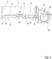
Fig. 1 is an end view of a crusher according to the invention, -
Fig. 2 is a perspective view of the crusher ofFig. 1 , -
Fig. 3 is a vertical cross-section of the crusher ofFigs. 1 and2 , -
Fig. 4 is a detail of the cross-section ofFig. 3 , and -
Fig. 5 is a horizontal cross-section of the lower part of the comminution vessel of the crusher. - The embodiment of the present invention shown in the drawing is an example of the invention provided to illustrate it and is not in any way to be construed as a limitation of the present invention.
- The embodiment of the
crusher 1 shown in the accompanying drawing is primarily intended for comminution of organic material such as animal excrements mixed with straw, organic industrial waste or food waste so that it is better suited for being fed to a biogas plant, also known as a biogas digester. Thecrusher 1 comprises acomminution vessel 2 having an innervertical wall 3 of a cylindrical cross-section with afunnel 4 at the top of thevessel 2 which constitutes an inlet of thecomminution vessel 2. A feeding device (not shown) may be provided as part of thecrusher 1 for controlled feeding of material into thevessel 2 through thefunnel 4. - A vertical drive shaft 5 extends through the
horizontal bottom wall 6 of thevessel 2 and carries acrushing tool 7 comprising ahub 8 rigidly connected to the drive shaft 5 and twochains 9 extending on opposing sides of thehub 8. Eachchain 9 is at oneend 10 fastened to thehub 8 and has an opposingfree end 11 carrying anend link 12 of thechain 9 acting as a hammer. Anelectric motor 13 is a drive means for the crushingtool 7 and is connected to the drive shaft 5 by means of abelt drive 14. The crushingtool 7 is arranged right above thebottom wall 6 so that thechains 9 during operation of thecrusher 1 will rotates parallel to and immediately above thebottom wall 6. - The
comminution vessel 2 has an outlet opening 15 formed in the bottom part of theside wall 3 of thevessel 2 as well as in thebottom wall 6 and the outlet opening 15 is formed so that thefree ends 11 of thechains 9 under operation of thecrusher 1 will extend out through the outlet opening 15, i.e. the outer part of theend links 12 of thechains 9 will pass out through the opening area defined by the of the edges of the outlet opening 15 in theinner walls comminution vessel 2 when theelectric motor 13 drives the crushingtool 7 to rotate during operation of thecrusher 1. The outlet opening 15 extends horizontally along an angle range of theinner wall 3 of thevessel 2 and in the vertical direction in a height sufficient to accommodate the passing of thefree ends 11 of thechains 9. - A
centerless conveyor screw 16 arranged in acylindrical housing 17 is arranged outside the outlet opening 15 of thecomminution vessel 2 of thecrusher 1 to convey the processed material away from the outlet opening 15. Theconveyor screw 16 is driven by means of anelectrical motor 18 with a variable speed which may be adjusted to control the flow rate of processed material out from thecomminution vessel 2 and thus the degree of processing of the material. - The
crusher 1 is suited for being operated in a continuous mode, where a control unit (not shown) of thecrusher 1 monitors the power consumption of theelectrical motor 13 driving thecrushing tool 7 and controls the operation of the material feeding device (not shown). The power consumption of themotor 13 is decreasing when the material contained within thevessel 2 is processed to a finer size and the feeding device is in response to a lowering of the power consumption activated to increase the feeding of material into thevessel 2 through the inlet opening 4 thereof in order to maintain the power consumption of themotor 13 and thus the processing rate of thecrusher 2 substantially constant. - The operation of the
crusher 1 to produce an output of material that has been comminuted to a suitable degree may be continuous by the fact that has been realised by the inventor of the present invention, that the material of the finest size has a tendency to move to the lowest part of thecomminution vessel 2 where thefree ends 11 of thechains 9 during rotation will force the material out through the outlet opening 15, and the fact that thesefree ends 11 extend out through the inner opening area of the outlet opening 15 ensures that the flow of material out through the outlet opening 15 is continuous and that the opening 15 will not be blocked by the material. - The crusher furthermore comprises nozzles (not shown) for adding a liquid, preferably farm slurry to the interior of the comminuting
vessel 2 in order to prevent the formation of an annulus of sticky, partly comminuted organic material, which may happen during comminution of some types of material, in particular when such material as livestock bedding is fed into the crusher. The amount of liquid added to thevessel 2 may preferably be controlled parallel to the feeding device for feeding the organic material into the inlet opening of thecomminution vessel 2 so that the amount of liquid matches the amount of material fed by the feeding device. Alternatively, the feeding device may comprise weighting means for determining the weight of the material fed into the vessel and the control means may then control the supply of liquid in response to said weight of material fed to thevessel 2. -
- 1
- Crusher
- 2
- Commination vessel
- 3
- Inner vertical wall of comminution vessel
- 4
- Funnel defining inlet opening of comminution vessel
- 5
- Drive shaft
- 6
- Bottom wall of comminution vessel
- 7
- Crushing tool
- 8
- Hub of crushing tool
- 9
- Chains
- 10
- Inner end of chains
- 11
- Free end of chains
- 12
- End link of chains
- 13
- Electric motor driving crushing tool
- 14
- Belt drive
- 15
- Outlet opening
- 16
- Conveyor screw
- 17
- Housing of conveyor screw
- 18
- Electrical motor for driving the conveyor screw
Claims (15)
- A crusher (1) for comminuting material, in particular organic material, comprising a comminuting vessel (2) with an inner vertical side wall (3),a drive shaft (5) extending substantially vertically and centrally within said comminuting vessel,a crushing tool (7) arranged on said drive shaft within the comminuting vessel to rotate with the drive shaft, the crushing tool comprising at least one flexible, elongated crushing element (9) having a free end (11),the crusher furthermore comprising crusher drive means (13, 14) arranged to drive the rotation of said drive shaft,
the comminuting vessel having an inlet opening (4) and an outlet opening (15), wherein the outlet opening of the comminuting vessel is situated in the cylindrical wall of the comminuting vessel at the horizontal level of said at least one crushing element,
wherein the free end of the at least one crushing element extends out through the outlet opening during operation of the crusher when the drive means drives the rotation of the drive shaft and the crushing tool. - Crusher according to claim 1 further comprising a conveyor device (16, 17, 18) arranged for conveying processed material away from the outlet opening, the conveyor device comprising a conveying means (16) and a conveyor drive means (18) for driving the conveying means.
- Crusher according to claim 2, wherein the conveying means comprises a conveyor screw, in particular a centerless conveyor screw.
- Crusher according to any of claims 1 to 3, wherein said inner wall of the comminuting vessel is of a substantially cylindrical cross-section.
- Crusher according to any of the preceding claims, wherein the crushing tool comprises at least two flexible, elongated crushing elements each having a free end which extends out through the outlet opening during operation of the crusher when the drive means drives the rotation of the drive shaft and the crushing tool.
- Crusher according to claim 5, wherein the crushing elements of the crushing tool are arranged in balance around the drive shaft.
- Crusher according to any of the preceding claims, wherein the crushing element or elements are formed of chains.
- Crusher according to any of the preceding claims, wherein the comminuting vessel further comprises a bottom wall (6) immediately below the horizontal plane of the crushing tool.
- Crusher according to claim 8, wherein said bottom wall is substantially horizontal.
- Crusher according to claim 8 or 9, wherein the outlet opening is formed in said bottom wall as well as in said side wall.
- Crusher according to any of the preceding claims further comprising a driven feeding device for feeding material into the inlet opening.
- Crusher according to claim 11 further comprising control means arranged to receive an input relating to the power consumption of the crusher drive means during operation of the crusher and to control the operation of said feeding device in response to the input.
- Crusher according to any of the preceding claims, further comprising a liquid supplying device for supplying liquid into the comminuting vessel (2) during operation of the crusher (1).
- Crusher according to claim 13, wherein the amount of liquid supplied into the comminuting vessel (2) during operation of the crusher (1) is controlled by control means in response to the feeding of material into the inlet opening (4).
- Crusher according to claim 14 comprising feeding measuring means for determining the amount of material fed into the inlet opening (4) and providing an output accordingly to the control means for controlling the supply of liquid.
Applications Claiming Priority (2)
| Application Number | Priority Date | Filing Date | Title |
|---|---|---|---|
| DK201370256A DK177721B1 (en) | 2013-05-07 | 2013-05-07 | Crusher and use thereof |
| DKPA201370396 | 2013-07-12 |
Publications (3)
| Publication Number | Publication Date |
|---|---|
| EP2829325A2 EP2829325A2 (en) | 2015-01-28 |
| EP2829325A3 EP2829325A3 (en) | 2015-06-03 |
| EP2829325B1 true EP2829325B1 (en) | 2016-06-29 |
Family
ID=50630706
Family Applications (1)
| Application Number | Title | Priority Date | Filing Date |
|---|---|---|---|
| EP14167308.7A Not-in-force EP2829325B1 (en) | 2013-05-07 | 2014-05-07 | Crusher and use thereof |
Country Status (1)
| Country | Link |
|---|---|
| EP (1) | EP2829325B1 (en) |
Cited By (1)
| Publication number | Priority date | Publication date | Assignee | Title |
|---|---|---|---|---|
| CN107470006A (en) * | 2017-09-07 | 2017-12-15 | 袁福德 | One kind can category filter Chinese chestnut milling apparatus |
Families Citing this family (1)
| Publication number | Priority date | Publication date | Assignee | Title |
|---|---|---|---|---|
| AT522020B1 (en) * | 2018-12-20 | 2022-06-15 | Technik Man Gmbh | Device for crushing solids |
Family Cites Families (3)
| Publication number | Priority date | Publication date | Assignee | Title |
|---|---|---|---|---|
| DE19903526B4 (en) * | 1999-01-29 | 2018-04-12 | Andritz Mewa Gmbh | Separation device for products composed of different substances |
| AT407970B (en) * | 1999-06-02 | 2001-07-25 | Bacher Helmut | DEVICE AND METHOD FOR PROCESSING, IN PARTICULAR THERMOPLASTIC, PLASTIC MATERIAL |
| DE102006006096A1 (en) * | 2006-02-10 | 2007-08-16 | Altenburger Maschinen Jäckering GmbH | Apparatus and method for feeding moist and / or sticky products, in particular cellulose, in an air vortex mill |
-
2014
- 2014-05-07 EP EP14167308.7A patent/EP2829325B1/en not_active Not-in-force
Cited By (1)
| Publication number | Priority date | Publication date | Assignee | Title |
|---|---|---|---|---|
| CN107470006A (en) * | 2017-09-07 | 2017-12-15 | 袁福德 | One kind can category filter Chinese chestnut milling apparatus |
Also Published As
| Publication number | Publication date |
|---|---|
| EP2829325A3 (en) | 2015-06-03 |
| EP2829325A2 (en) | 2015-01-28 |
Similar Documents
| Publication | Publication Date | Title |
|---|---|---|
| CN106714545B (en) | Planting machine and agricultural unmanned plane | |
| CN107062872A (en) | A kind of agricultural paddy class path grain foodstuff drying device | |
| CN108658631A (en) | A kind of production equipment of excrement fowl organic fertilizer | |
| EP2829325B1 (en) | Crusher and use thereof | |
| KR101891335B1 (en) | Apparatus for crushing sludge of waste-water | |
| KR100836071B1 (en) | Processing device for synthetic material | |
| US9079723B2 (en) | Paper feeder and method of feeding paper | |
| DK177721B1 (en) | Crusher and use thereof | |
| US9649637B2 (en) | Device and method for processing materials | |
| CN210121502U (en) | Fine feeding workshop | |
| US7055769B2 (en) | Collider | |
| KR101283335B1 (en) | Cocoa husk automatic crushing and measure supply device | |
| US20190270090A1 (en) | Separator apparatus and method | |
| US612744A (en) | Almond huller and separator | |
| CN208894129U (en) | Production equipment for pesticide jelly | |
| CN102511208A (en) | Extrusion soil breaker | |
| RU2524258C1 (en) | Line of combined fodder production | |
| CN207549182U (en) | A kind of homogenizing bin | |
| RU2767617C1 (en) | Technological line for receiving and processing root crops | |
| KR102235160B1 (en) | Pepper Grinding Apparatus | |
| RU217471U1 (en) | FEED GRINDER | |
| KR20230075795A (en) | Haystack-feed crushing supply equipment | |
| CN221132115U (en) | Batching jar that unloading is even | |
| CN220520337U (en) | Anti-blocking mechanism for feed inlet of sludge dehydrator | |
| KR102122157B1 (en) | Feed mixer with a hydraulically driven side window |
Legal Events
| Date | Code | Title | Description |
|---|---|---|---|
| 17P | Request for examination filed |
Effective date: 20140507 |
|
| AK | Designated contracting states |
Kind code of ref document: A2 Designated state(s): AL AT BE BG CH CY CZ DE DK EE ES FI FR GB GR HR HU IE IS IT LI LT LU LV MC MK MT NL NO PL PT RO RS SE SI SK SM TR |
|
| AX | Request for extension of the european patent |
Extension state: BA ME |
|
| PUAI | Public reference made under article 153(3) epc to a published international application that has entered the european phase |
Free format text: ORIGINAL CODE: 0009012 |
|
| PUAL | Search report despatched |
Free format text: ORIGINAL CODE: 0009013 |
|
| AK | Designated contracting states |
Kind code of ref document: A3 Designated state(s): AL AT BE BG CH CY CZ DE DK EE ES FI FR GB GR HR HU IE IS IT LI LT LU LV MC MK MT NL NO PL PT RO RS SE SI SK SM TR |
|
| AX | Request for extension of the european patent |
Extension state: BA ME |
|
| RIC1 | Information provided on ipc code assigned before grant |
Ipc: B02C 13/286 20060101ALI20150428BHEP Ipc: B02C 23/18 20060101ALI20150428BHEP Ipc: B02C 13/28 20060101ALI20150428BHEP Ipc: B02C 13/16 20060101AFI20150428BHEP |
|
| R17P | Request for examination filed (corrected) |
Effective date: 20151130 |
|
| RBV | Designated contracting states (corrected) |
Designated state(s): AL AT BE BG CH CY CZ DE DK EE ES FI FR GB GR HR HU IE IS IT LI LT LU LV MC MK MT NL NO PL PT RO RS SE SI SK SM TR |
|
| GRAP | Despatch of communication of intention to grant a patent |
Free format text: ORIGINAL CODE: EPIDOSNIGR1 |
|
| INTG | Intention to grant announced |
Effective date: 20160118 |
|
| GRAS | Grant fee paid |
Free format text: ORIGINAL CODE: EPIDOSNIGR3 |
|
| GRAA | (expected) grant |
Free format text: ORIGINAL CODE: 0009210 |
|
| AK | Designated contracting states |
Kind code of ref document: B1 Designated state(s): AL AT BE BG CH CY CZ DE DK EE ES FI FR GB GR HR HU IE IS IT LI LT LU LV MC MK MT NL NO PL PT RO RS SE SI SK SM TR |
|
| REG | Reference to a national code |
Ref country code: GB Ref legal event code: FG4D |
|
| REG | Reference to a national code |
Ref country code: CH Ref legal event code: EP |
|
| REG | Reference to a national code |
Ref country code: AT Ref legal event code: REF Ref document number: 808653 Country of ref document: AT Kind code of ref document: T Effective date: 20160715 |
|
| REG | Reference to a national code |
Ref country code: IE Ref legal event code: FG4D |
|
| REG | Reference to a national code |
Ref country code: DE Ref legal event code: R096 Ref document number: 602014002450 Country of ref document: DE |
|
| REG | Reference to a national code |
Ref country code: NL Ref legal event code: FP |
|
| REG | Reference to a national code |
Ref country code: LT Ref legal event code: MG4D |
|
| PG25 | Lapsed in a contracting state [announced via postgrant information from national office to epo] |
Ref country code: LT Free format text: LAPSE BECAUSE OF FAILURE TO SUBMIT A TRANSLATION OF THE DESCRIPTION OR TO PAY THE FEE WITHIN THE PRESCRIBED TIME-LIMIT Effective date: 20160629 Ref country code: NO Free format text: LAPSE BECAUSE OF FAILURE TO SUBMIT A TRANSLATION OF THE DESCRIPTION OR TO PAY THE FEE WITHIN THE PRESCRIBED TIME-LIMIT Effective date: 20160929 Ref country code: FI Free format text: LAPSE BECAUSE OF FAILURE TO SUBMIT A TRANSLATION OF THE DESCRIPTION OR TO PAY THE FEE WITHIN THE PRESCRIBED TIME-LIMIT Effective date: 20160629 |
|
| PG25 | Lapsed in a contracting state [announced via postgrant information from national office to epo] |
Ref country code: GR Free format text: LAPSE BECAUSE OF FAILURE TO SUBMIT A TRANSLATION OF THE DESCRIPTION OR TO PAY THE FEE WITHIN THE PRESCRIBED TIME-LIMIT Effective date: 20160930 Ref country code: SE Free format text: LAPSE BECAUSE OF FAILURE TO SUBMIT A TRANSLATION OF THE DESCRIPTION OR TO PAY THE FEE WITHIN THE PRESCRIBED TIME-LIMIT Effective date: 20160629 Ref country code: RS Free format text: LAPSE BECAUSE OF FAILURE TO SUBMIT A TRANSLATION OF THE DESCRIPTION OR TO PAY THE FEE WITHIN THE PRESCRIBED TIME-LIMIT Effective date: 20160629 Ref country code: HR Free format text: LAPSE BECAUSE OF FAILURE TO SUBMIT A TRANSLATION OF THE DESCRIPTION OR TO PAY THE FEE WITHIN THE PRESCRIBED TIME-LIMIT Effective date: 20160629 Ref country code: LV Free format text: LAPSE BECAUSE OF FAILURE TO SUBMIT A TRANSLATION OF THE DESCRIPTION OR TO PAY THE FEE WITHIN THE PRESCRIBED TIME-LIMIT Effective date: 20160629 |
|
| REG | Reference to a national code |
Ref country code: AT Ref legal event code: MK05 Ref document number: 808653 Country of ref document: AT Kind code of ref document: T Effective date: 20160629 |
|
| PG25 | Lapsed in a contracting state [announced via postgrant information from national office to epo] |
Ref country code: EE Free format text: LAPSE BECAUSE OF FAILURE TO SUBMIT A TRANSLATION OF THE DESCRIPTION OR TO PAY THE FEE WITHIN THE PRESCRIBED TIME-LIMIT Effective date: 20160629 Ref country code: CZ Free format text: LAPSE BECAUSE OF FAILURE TO SUBMIT A TRANSLATION OF THE DESCRIPTION OR TO PAY THE FEE WITHIN THE PRESCRIBED TIME-LIMIT Effective date: 20160629 Ref country code: SK Free format text: LAPSE BECAUSE OF FAILURE TO SUBMIT A TRANSLATION OF THE DESCRIPTION OR TO PAY THE FEE WITHIN THE PRESCRIBED TIME-LIMIT Effective date: 20160629 Ref country code: RO Free format text: LAPSE BECAUSE OF FAILURE TO SUBMIT A TRANSLATION OF THE DESCRIPTION OR TO PAY THE FEE WITHIN THE PRESCRIBED TIME-LIMIT Effective date: 20160629 Ref country code: IT Free format text: LAPSE BECAUSE OF FAILURE TO SUBMIT A TRANSLATION OF THE DESCRIPTION OR TO PAY THE FEE WITHIN THE PRESCRIBED TIME-LIMIT Effective date: 20160629 Ref country code: IS Free format text: LAPSE BECAUSE OF FAILURE TO SUBMIT A TRANSLATION OF THE DESCRIPTION OR TO PAY THE FEE WITHIN THE PRESCRIBED TIME-LIMIT Effective date: 20161029 |
|
| PG25 | Lapsed in a contracting state [announced via postgrant information from national office to epo] |
Ref country code: AT Free format text: LAPSE BECAUSE OF FAILURE TO SUBMIT A TRANSLATION OF THE DESCRIPTION OR TO PAY THE FEE WITHIN THE PRESCRIBED TIME-LIMIT Effective date: 20160629 Ref country code: ES Free format text: LAPSE BECAUSE OF FAILURE TO SUBMIT A TRANSLATION OF THE DESCRIPTION OR TO PAY THE FEE WITHIN THE PRESCRIBED TIME-LIMIT Effective date: 20160629 Ref country code: SM Free format text: LAPSE BECAUSE OF FAILURE TO SUBMIT A TRANSLATION OF THE DESCRIPTION OR TO PAY THE FEE WITHIN THE PRESCRIBED TIME-LIMIT Effective date: 20160629 Ref country code: BE Free format text: LAPSE BECAUSE OF FAILURE TO SUBMIT A TRANSLATION OF THE DESCRIPTION OR TO PAY THE FEE WITHIN THE PRESCRIBED TIME-LIMIT Effective date: 20160629 Ref country code: PL Free format text: LAPSE BECAUSE OF FAILURE TO SUBMIT A TRANSLATION OF THE DESCRIPTION OR TO PAY THE FEE WITHIN THE PRESCRIBED TIME-LIMIT Effective date: 20160629 Ref country code: PT Free format text: LAPSE BECAUSE OF FAILURE TO SUBMIT A TRANSLATION OF THE DESCRIPTION OR TO PAY THE FEE WITHIN THE PRESCRIBED TIME-LIMIT Effective date: 20161031 |
|
| REG | Reference to a national code |
Ref country code: DE Ref legal event code: R097 Ref document number: 602014002450 Country of ref document: DE |
|
| REG | Reference to a national code |
Ref country code: FR Ref legal event code: PLFP Year of fee payment: 4 |
|
| PG25 | Lapsed in a contracting state [announced via postgrant information from national office to epo] |
Ref country code: DK Free format text: LAPSE BECAUSE OF FAILURE TO SUBMIT A TRANSLATION OF THE DESCRIPTION OR TO PAY THE FEE WITHIN THE PRESCRIBED TIME-LIMIT Effective date: 20160629 |
|
| 26N | No opposition filed |
Effective date: 20170330 |
|
| PLBE | No opposition filed within time limit |
Free format text: ORIGINAL CODE: 0009261 |
|
| STAA | Information on the status of an ep patent application or granted ep patent |
Free format text: STATUS: NO OPPOSITION FILED WITHIN TIME LIMIT |
|
| PGFP | Annual fee paid to national office [announced via postgrant information from national office to epo] |
Ref country code: NL Payment date: 20170512 Year of fee payment: 4 |
|
| PGFP | Annual fee paid to national office [announced via postgrant information from national office to epo] |
Ref country code: FR Payment date: 20170511 Year of fee payment: 4 Ref country code: DE Payment date: 20170509 Year of fee payment: 4 |
|
| PG25 | Lapsed in a contracting state [announced via postgrant information from national office to epo] |
Ref country code: BG Free format text: LAPSE BECAUSE OF FAILURE TO SUBMIT A TRANSLATION OF THE DESCRIPTION OR TO PAY THE FEE WITHIN THE PRESCRIBED TIME-LIMIT Effective date: 20160929 Ref country code: SI Free format text: LAPSE BECAUSE OF FAILURE TO SUBMIT A TRANSLATION OF THE DESCRIPTION OR TO PAY THE FEE WITHIN THE PRESCRIBED TIME-LIMIT Effective date: 20160629 Ref country code: LU Free format text: LAPSE BECAUSE OF NON-PAYMENT OF DUE FEES Effective date: 20170531 |
|
| PGFP | Annual fee paid to national office [announced via postgrant information from national office to epo] |
Ref country code: IE Payment date: 20170810 Year of fee payment: 4 |
|
| REG | Reference to a national code |
Ref country code: CH Ref legal event code: PL |
|
| PG25 | Lapsed in a contracting state [announced via postgrant information from national office to epo] |
Ref country code: MC Free format text: LAPSE BECAUSE OF FAILURE TO SUBMIT A TRANSLATION OF THE DESCRIPTION OR TO PAY THE FEE WITHIN THE PRESCRIBED TIME-LIMIT Effective date: 20160629 |
|
| PG25 | Lapsed in a contracting state [announced via postgrant information from national office to epo] |
Ref country code: CH Free format text: LAPSE BECAUSE OF NON-PAYMENT OF DUE FEES Effective date: 20170531 Ref country code: LI Free format text: LAPSE BECAUSE OF NON-PAYMENT OF DUE FEES Effective date: 20170531 |
|
| PG25 | Lapsed in a contracting state [announced via postgrant information from national office to epo] |
Ref country code: LU Free format text: LAPSE BECAUSE OF NON-PAYMENT OF DUE FEES Effective date: 20170507 |
|
| PG25 | Lapsed in a contracting state [announced via postgrant information from national office to epo] |
Ref country code: MT Free format text: LAPSE BECAUSE OF NON-PAYMENT OF DUE FEES Effective date: 20170507 |
|
| PG25 | Lapsed in a contracting state [announced via postgrant information from national office to epo] |
Ref country code: AL Free format text: LAPSE BECAUSE OF FAILURE TO SUBMIT A TRANSLATION OF THE DESCRIPTION OR TO PAY THE FEE WITHIN THE PRESCRIBED TIME-LIMIT Effective date: 20160629 |
|
| REG | Reference to a national code |
Ref country code: DE Ref legal event code: R119 Ref document number: 602014002450 Country of ref document: DE |
|
| REG | Reference to a national code |
Ref country code: NL Ref legal event code: MM Effective date: 20180601 |
|
| GBPC | Gb: european patent ceased through non-payment of renewal fee |
Effective date: 20180507 |
|
| REG | Reference to a national code |
Ref country code: IE Ref legal event code: MM4A |
|
| PG25 | Lapsed in a contracting state [announced via postgrant information from national office to epo] |
Ref country code: DE Free format text: LAPSE BECAUSE OF NON-PAYMENT OF DUE FEES Effective date: 20181201 Ref country code: GB Free format text: LAPSE BECAUSE OF NON-PAYMENT OF DUE FEES Effective date: 20180507 Ref country code: IE Free format text: LAPSE BECAUSE OF NON-PAYMENT OF DUE FEES Effective date: 20180507 Ref country code: NL Free format text: LAPSE BECAUSE OF NON-PAYMENT OF DUE FEES Effective date: 20180601 Ref country code: FR Free format text: LAPSE BECAUSE OF NON-PAYMENT OF DUE FEES Effective date: 20180531 |
|
| PG25 | Lapsed in a contracting state [announced via postgrant information from national office to epo] |
Ref country code: HU Free format text: LAPSE BECAUSE OF FAILURE TO SUBMIT A TRANSLATION OF THE DESCRIPTION OR TO PAY THE FEE WITHIN THE PRESCRIBED TIME-LIMIT; INVALID AB INITIO Effective date: 20140507 |
|
| PG25 | Lapsed in a contracting state [announced via postgrant information from national office to epo] |
Ref country code: CY Free format text: LAPSE BECAUSE OF FAILURE TO SUBMIT A TRANSLATION OF THE DESCRIPTION OR TO PAY THE FEE WITHIN THE PRESCRIBED TIME-LIMIT Effective date: 20160629 |
|
| PG25 | Lapsed in a contracting state [announced via postgrant information from national office to epo] |
Ref country code: MK Free format text: LAPSE BECAUSE OF FAILURE TO SUBMIT A TRANSLATION OF THE DESCRIPTION OR TO PAY THE FEE WITHIN THE PRESCRIBED TIME-LIMIT Effective date: 20160629 |
|
| PG25 | Lapsed in a contracting state [announced via postgrant information from national office to epo] |
Ref country code: TR Free format text: LAPSE BECAUSE OF FAILURE TO SUBMIT A TRANSLATION OF THE DESCRIPTION OR TO PAY THE FEE WITHIN THE PRESCRIBED TIME-LIMIT Effective date: 20160629 |