EP2828455B1 - Manipulationssicheres riegelschloss zum verschliessen eines frachtbehälters - Google Patents
Manipulationssicheres riegelschloss zum verschliessen eines frachtbehälters Download PDFInfo
- Publication number
- EP2828455B1 EP2828455B1 EP13764844.0A EP13764844A EP2828455B1 EP 2828455 B1 EP2828455 B1 EP 2828455B1 EP 13764844 A EP13764844 A EP 13764844A EP 2828455 B1 EP2828455 B1 EP 2828455B1
- Authority
- EP
- European Patent Office
- Prior art keywords
- bolt
- receiving member
- lock device
- circuit
- receiving
- Prior art date
- Legal status (The legal status is an assumption and is not a legal conclusion. Google has not performed a legal analysis and makes no representation as to the accuracy of the status listed.)
- Active
Links
- 230000001953 sensory effect Effects 0.000 claims description 19
- 238000000034 method Methods 0.000 claims description 15
- 230000037361 pathway Effects 0.000 claims description 6
- 239000002184 metal Substances 0.000 claims description 5
- 239000004033 plastic Substances 0.000 claims description 3
- 229920003023 plastic Polymers 0.000 claims description 3
- 230000004044 response Effects 0.000 claims description 3
- 239000010409 thin film Substances 0.000 claims description 2
- 238000009429 electrical wiring Methods 0.000 claims 1
- 239000008393 encapsulating agent Substances 0.000 description 12
- 239000004020 conductor Substances 0.000 description 9
- 239000000463 material Substances 0.000 description 6
- 238000003780 insertion Methods 0.000 description 5
- 230000037431 insertion Effects 0.000 description 5
- 230000013011 mating Effects 0.000 description 5
- 230000004323 axial length Effects 0.000 description 4
- 238000005516 engineering process Methods 0.000 description 4
- 230000008901 benefit Effects 0.000 description 3
- 238000004891 communication Methods 0.000 description 2
- 238000010586 diagram Methods 0.000 description 2
- 238000004519 manufacturing process Methods 0.000 description 2
- 230000008569 process Effects 0.000 description 2
- 238000007789 sealing Methods 0.000 description 2
- 230000015556 catabolic process Effects 0.000 description 1
- 238000010276 construction Methods 0.000 description 1
- 230000003247 decreasing effect Effects 0.000 description 1
- 238000006731 degradation reaction Methods 0.000 description 1
- 230000000694 effects Effects 0.000 description 1
- 239000012777 electrically insulating material Substances 0.000 description 1
- 238000005538 encapsulation Methods 0.000 description 1
- 230000006870 function Effects 0.000 description 1
- 239000007769 metal material Substances 0.000 description 1
- 238000000465 moulding Methods 0.000 description 1
- 230000000737 periodic effect Effects 0.000 description 1
- 238000012545 processing Methods 0.000 description 1
- 239000007787 solid Substances 0.000 description 1
- 238000000638 solvent extraction Methods 0.000 description 1
- 239000000758 substrate Substances 0.000 description 1
- 238000011179 visual inspection Methods 0.000 description 1
Images
Classifications
-
- E—FIXED CONSTRUCTIONS
- E05—LOCKS; KEYS; WINDOW OR DOOR FITTINGS; SAFES
- E05B—LOCKS; ACCESSORIES THEREFOR; HANDCUFFS
- E05B39/00—Locks giving indication of authorised or unauthorised unlocking
- E05B39/04—Locks giving indication of authorised or unauthorised unlocking with counting or registering devices
-
- B—PERFORMING OPERATIONS; TRANSPORTING
- B65—CONVEYING; PACKING; STORING; HANDLING THIN OR FILAMENTARY MATERIAL
- B65D—CONTAINERS FOR STORAGE OR TRANSPORT OF ARTICLES OR MATERIALS, e.g. BAGS, BARRELS, BOTTLES, BOXES, CANS, CARTONS, CRATES, DRUMS, JARS, TANKS, HOPPERS, FORWARDING CONTAINERS; ACCESSORIES, CLOSURES, OR FITTINGS THEREFOR; PACKAGING ELEMENTS; PACKAGES
- B65D90/00—Component parts, details or accessories for large containers
- B65D90/22—Safety features
-
- E—FIXED CONSTRUCTIONS
- E05—LOCKS; KEYS; WINDOW OR DOOR FITTINGS; SAFES
- E05B—LOCKS; ACCESSORIES THEREFOR; HANDCUFFS
- E05B17/00—Accessories in connection with locks
-
- E—FIXED CONSTRUCTIONS
- E05—LOCKS; KEYS; WINDOW OR DOOR FITTINGS; SAFES
- E05B—LOCKS; ACCESSORIES THEREFOR; HANDCUFFS
- E05B17/00—Accessories in connection with locks
- E05B17/22—Means for operating or controlling lock or fastening device accessories, i.e. other than the fastening members, e.g. switches, indicators
-
- E—FIXED CONSTRUCTIONS
- E05—LOCKS; KEYS; WINDOW OR DOOR FITTINGS; SAFES
- E05B—LOCKS; ACCESSORIES THEREFOR; HANDCUFFS
- E05B39/00—Locks giving indication of authorised or unauthorised unlocking
- E05B39/005—Locks with means for tracking the location of locked items, e.g. freight containers
-
- E—FIXED CONSTRUCTIONS
- E05—LOCKS; KEYS; WINDOW OR DOOR FITTINGS; SAFES
- E05B—LOCKS; ACCESSORIES THEREFOR; HANDCUFFS
- E05B73/00—Devices for locking portable objects against unauthorised removal; Miscellaneous locking devices
- E05B73/0017—Anti-theft devices, e.g. tags or monitors, fixed to articles, e.g. clothes, and to be removed at the check-out of shops
-
- G—PHYSICS
- G06—COMPUTING; CALCULATING OR COUNTING
- G06K—GRAPHICAL DATA READING; PRESENTATION OF DATA; RECORD CARRIERS; HANDLING RECORD CARRIERS
- G06K19/00—Record carriers for use with machines and with at least a part designed to carry digital markings
- G06K19/06—Record carriers for use with machines and with at least a part designed to carry digital markings characterised by the kind of the digital marking, e.g. shape, nature, code
- G06K19/067—Record carriers with conductive marks, printed circuits or semiconductor circuit elements, e.g. credit or identity cards also with resonating or responding marks without active components
- G06K19/07—Record carriers with conductive marks, printed circuits or semiconductor circuit elements, e.g. credit or identity cards also with resonating or responding marks without active components with integrated circuit chips
- G06K19/077—Constructional details, e.g. mounting of circuits in the carrier
- G06K19/07749—Constructional details, e.g. mounting of circuits in the carrier the record carrier being capable of non-contact communication, e.g. constructional details of the antenna of a non-contact smart card
- G06K19/07798—Constructional details, e.g. mounting of circuits in the carrier the record carrier being capable of non-contact communication, e.g. constructional details of the antenna of a non-contact smart card part of the antenna or the integrated circuit being adapted for rupturing or breaking, e.g. record carriers functioning as sealing devices for detecting not-authenticated opening of containers
-
- G—PHYSICS
- G07—CHECKING-DEVICES
- G07C—TIME OR ATTENDANCE REGISTERS; REGISTERING OR INDICATING THE WORKING OF MACHINES; GENERATING RANDOM NUMBERS; VOTING OR LOTTERY APPARATUS; ARRANGEMENTS, SYSTEMS OR APPARATUS FOR CHECKING NOT PROVIDED FOR ELSEWHERE
- G07C1/00—Registering, indicating or recording the time of events or elapsed time, e.g. time-recorders for work people
- G07C1/32—Time-recording locks
-
- G—PHYSICS
- G09—EDUCATION; CRYPTOGRAPHY; DISPLAY; ADVERTISING; SEALS
- G09F—DISPLAYING; ADVERTISING; SIGNS; LABELS OR NAME-PLATES; SEALS
- G09F3/00—Labels, tag tickets, or similar identification or indication means; Seals; Postage or like stamps
- G09F3/02—Forms or constructions
- G09F3/03—Forms or constructions of security seals
- G09F3/0305—Forms or constructions of security seals characterised by the type of seal used
- G09F3/0317—Forms or constructions of security seals characterised by the type of seal used having bolt like sealing means
-
- G—PHYSICS
- G09—EDUCATION; CRYPTOGRAPHY; DISPLAY; ADVERTISING; SEALS
- G09F—DISPLAYING; ADVERTISING; SIGNS; LABELS OR NAME-PLATES; SEALS
- G09F3/00—Labels, tag tickets, or similar identification or indication means; Seals; Postage or like stamps
- G09F3/02—Forms or constructions
- G09F3/03—Forms or constructions of security seals
- G09F3/0305—Forms or constructions of security seals characterised by the type of seal used
- G09F3/0329—Forms or constructions of security seals characterised by the type of seal used having electronic sealing means
-
- B—PERFORMING OPERATIONS; TRANSPORTING
- B65—CONVEYING; PACKING; STORING; HANDLING THIN OR FILAMENTARY MATERIAL
- B65D—CONTAINERS FOR STORAGE OR TRANSPORT OF ARTICLES OR MATERIALS, e.g. BAGS, BARRELS, BOTTLES, BOXES, CANS, CARTONS, CRATES, DRUMS, JARS, TANKS, HOPPERS, FORWARDING CONTAINERS; ACCESSORIES, CLOSURES, OR FITTINGS THEREFOR; PACKAGING ELEMENTS; PACKAGES
- B65D2211/00—Anti-theft means
-
- B—PERFORMING OPERATIONS; TRANSPORTING
- B65—CONVEYING; PACKING; STORING; HANDLING THIN OR FILAMENTARY MATERIAL
- B65D—CONTAINERS FOR STORAGE OR TRANSPORT OF ARTICLES OR MATERIALS, e.g. BAGS, BARRELS, BOTTLES, BOXES, CANS, CARTONS, CRATES, DRUMS, JARS, TANKS, HOPPERS, FORWARDING CONTAINERS; ACCESSORIES, CLOSURES, OR FITTINGS THEREFOR; PACKAGING ELEMENTS; PACKAGES
- B65D2401/00—Tamper-indicating means
-
- E—FIXED CONSTRUCTIONS
- E05—LOCKS; KEYS; WINDOW OR DOOR FITTINGS; SAFES
- E05B—LOCKS; ACCESSORIES THEREFOR; HANDCUFFS
- E05B47/00—Operating or controlling locks or other fastening devices by electric or magnetic means
- E05B2047/0048—Circuits, feeding, monitoring
- E05B2047/0067—Monitoring
-
- E—FIXED CONSTRUCTIONS
- E05—LOCKS; KEYS; WINDOW OR DOOR FITTINGS; SAFES
- E05B—LOCKS; ACCESSORIES THEREFOR; HANDCUFFS
- E05B47/00—Operating or controlling locks or other fastening devices by electric or magnetic means
- E05B2047/0072—Operation
-
- E—FIXED CONSTRUCTIONS
- E05—LOCKS; KEYS; WINDOW OR DOOR FITTINGS; SAFES
- E05B—LOCKS; ACCESSORIES THEREFOR; HANDCUFFS
- E05B47/00—Operating or controlling locks or other fastening devices by electric or magnetic means
- E05B2047/0097—Operating or controlling locks or other fastening devices by electric or magnetic means including means for monitoring voltage, e.g. for indicating low battery state
-
- Y—GENERAL TAGGING OF NEW TECHNOLOGICAL DEVELOPMENTS; GENERAL TAGGING OF CROSS-SECTIONAL TECHNOLOGIES SPANNING OVER SEVERAL SECTIONS OF THE IPC; TECHNICAL SUBJECTS COVERED BY FORMER USPC CROSS-REFERENCE ART COLLECTIONS [XRACs] AND DIGESTS
- Y10—TECHNICAL SUBJECTS COVERED BY FORMER USPC
- Y10T—TECHNICAL SUBJECTS COVERED BY FORMER US CLASSIFICATION
- Y10T70/00—Locks
- Y10T70/60—Systems
- Y10T70/625—Operation and control
-
- Y—GENERAL TAGGING OF NEW TECHNOLOGICAL DEVELOPMENTS; GENERAL TAGGING OF CROSS-SECTIONAL TECHNOLOGIES SPANNING OVER SEVERAL SECTIONS OF THE IPC; TECHNICAL SUBJECTS COVERED BY FORMER USPC CROSS-REFERENCE ART COLLECTIONS [XRACs] AND DIGESTS
- Y10—TECHNICAL SUBJECTS COVERED BY FORMER USPC
- Y10T—TECHNICAL SUBJECTS COVERED BY FORMER US CLASSIFICATION
- Y10T70/00—Locks
- Y10T70/80—Parts, attachments, accessories and adjuncts
- Y10T70/8027—Condition indicators
- Y10T70/8054—With recorder
- Y10T70/8081—Electric
-
- Y—GENERAL TAGGING OF NEW TECHNOLOGICAL DEVELOPMENTS; GENERAL TAGGING OF CROSS-SECTIONAL TECHNOLOGIES SPANNING OVER SEVERAL SECTIONS OF THE IPC; TECHNICAL SUBJECTS COVERED BY FORMER USPC CROSS-REFERENCE ART COLLECTIONS [XRACs] AND DIGESTS
- Y10—TECHNICAL SUBJECTS COVERED BY FORMER USPC
- Y10T—TECHNICAL SUBJECTS COVERED BY FORMER US CLASSIFICATION
- Y10T70/00—Locks
- Y10T70/80—Parts, attachments, accessories and adjuncts
- Y10T70/8027—Condition indicators
- Y10T70/8216—Tampering detector
Definitions
- Various embodiments concern the field of bolt locks for shipping containers. More particularly, various embodiments are directed to intelligent bolt locks which, if tampered with, can report the day and time that they have been tampered with.
- Bolt locks are frequently placed on shipping containers to prevent access to the container's contents by unauthorized parties.
- a bolt lock can be locked, but it cannot be unlocked-that is to say, when the container finally reaches its intended destination, the bolt has to be split open with bolt cutters in order to access the contents of the container.
- a bolt lock is a one-time use device.
- bolt locks typically include a metal bolt which is inserted through the hasps of cargo container doors.
- One end of the bolt includes a head which is substantially large enough to prevent the bolt from sliding out of the hasps in one direction.
- the other end of the bolt is designed to be inserted into a receiving member. Once the bolt is inserted into the receiving member (which is large enough to prevent the bolt from being slid of the hasps in the other direction), the bolt is then locked into place.
- the legally responsible party will be predicated upon which party had possession of the container when the theft actually occurred. For example, if the theft occurred after the container was locked, but before the container was provided to the shipper, the missing items are typically the seller's responsibility. If the theft occurred during transit, the missing items can be the shipper's responsibility or its insurer (unless explicitly disclaimed in the contract). If the theft occurred after the shipper delivered the container to the purchaser's storage facility, the missing items are no longer the seller or shipper's responsibility, but rather, it is the purchaser's loss.
- US2010/253099A1 discloses a locking arrangement for securely sealing the doors of a freight container.
- the locking arrangement comprises a sealing device comprising a bolt seal and a cable.
- the bolt seal comprises an insertion bolt comprising an elongated body, an enlarged base and a securing tip.
- the bolt seal further comprises a locking bush into which the securing tip is inserted.
- the cable comprises a first end and a second end joined to the bolt seal.
- the device can include a receiving member, a conductive bolt member adapted to be snap-locked into the receiving member, and a plastic encapsulant which tethers the bolt member to the receiving member.
- the encapsulant can contain an electrically conductive medium, such as a wire, which runs from the receiving member to the second end the bolt.
- a sensory circuit disposed within the receiving member can be configured to sense whether the circuit has been interrupted (e.g., if the bolt has been cut). In the event of an interruption, the circuit can record the present time and/or date in memory.
- An RFID transponder disposed within the encapsulant or the receiving member can then transmit the recorded date/time to an RFID interrogator if a dispute subsequently arises as to when the lock had been broken.
- a bolt lock device as defined in claim 1.
- Disclosed is a device and method for aiding with the determination of liability for a theft by knowing when a shipping container had been accessed by an unauthorized party.
- the device is an alternative to conventional bolt seals or other types of cargo container seals and provides a record of the time of access.
- a transponder disposed within in the lock can be queried using a suitable reader to determine whether a tamper event was recorded. If a tamper event was recorded, the date and time of the event can then be transmitted to the reader. The date and time of the tamper event makes it substantially easier to determine which party was in possession of the cargo container when the tamper event occurred (and consequently, which party is legally responsible for covering the loss).
- transponder can be repeatedly queried while the container is en route, particularly each time possession of the cargo container changes hands. This process can assist law enforcement since theft can be discovered more immediately (rather than, for example, being discovered upon ultimate delivery to the purchaser, which is sometimes weeks after the day that the theft occurred).
- the bolt lock device includes a bolt member and a receiving member.
- the bolt member is intended to be inserted through one or more hasps, with one end of the bolt member being inserted into the receiving member.
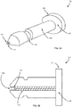
- FIG. 1A is a perspective view of an exemplary bolt member.
- the bolt member 102 can be made of metal or some other material.
- bolt member 102 can have a first end 104 adapted for insertion into a receiving member 202 (shown in FIG. 2 ), and a lock groove 116 for locking the bolt member 102 to the receiving member 202.
- the second end 106 of the bolt member 102 can form a head 108 which is substantially larger than the diameter of the hasps of cargo container doors (not shown) and therefore also substantially larger than the diameter of the shaft 109 of the bolt.
- the head 108 can thus serve to prevent the bolt member 102 from sliding through the hasps of the cargo container door in a first direction.
- FIG. 1B is a cross-sectional view of the exemplary bolt member depicted in FIG. 1A .
- the bolt member 102 can have a conductive center 110 running the axial length of the bolt.
- the conductive center 110 can be made of the same material as the structural part of the bolt (e.g., metallic), or it can be made of a different material.
- the conductive center 110 can consist of conductive wiring.
- the conductive center 110 can be electrically insulated from the structural portion of the bolt.
- An insulated core within which the conductive center lies can have a small diameter to minimize degradation in the physical strength of the structural part of the bolt member 102.
- the conductive center 110 can be surrounded with a second material having electrically insulating material or dielectric properties.
- the conductive center 110 can be adapted to interface with one or electrical contacts 212 of a circuit 206 disposed within a receiving member 202 (shown in FIG. 2 ).
- pin connector 112 can be a female connector adapted to receive one or more pins through a pin connector opening 114 positioned at the first end 104 of the bolt member 102.
- the conductive center 110 can terminate at the head 108 and form a conductive pathway through metal in the head 108 and metal in the shaft 109 in order to complete the circuit.
- the conductor 110 can simply wrap backwards upon itself after it has traversed the length of the bolt member 102.
- the conductor or conductive material 110 running through the center of the bolt member 102
- the conductor or conductive material need not necessarily run through the center of the bolt member 102, but can be positioned differently in other examples.
- the conductor or conductive material can be radially offset by some distance from the center of the shaft 108, including, for example, being positioned at a radial edge of shaft 109.
- the conductor or conductive material can run through multiple locations of the bolt member 102.
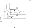
- FIG. 2 is a cross sectional view of an exemplary receiving member according to one example.
- the receiving member 202 can be configured to receive the bolt member 102 inserted therein and prevent its withdrawal, thereby locking it into place.
- lock ring 204 disposed within the receiving member 202 is adapted to interface with lock groove 116 (shown in FIG. 1A ) in order to facilitate the locking.
- Receiving member 202 can include a circuit 206 adapted to interface with conductive center 110 (shown in FIG. IB) via a set of electrical contacts 212.
- electrical contacts 212 can include a set of connectors, such as one or more mating pins adapted to be inserted with pin connector 112 of the bolt member 102. Instead of mating pins, note that other types of electrical contacts 212 can be used in the alternative.
- the first end 104 of the bolt member 102 can be shaped specifically to facilitate its insertion into the receiving member 202, and to electrically interface with one or more electrical contacts 212 formed in the receiving member 202.
- a continuous circuit is formed from one electrical contact 212 through the conductive center 110, across length of the bolt member 102, up to its head 108, returning through the metal material of which the bolt is made, and then back to a second electrical contact 212.
- the circuit 206 can be a sensory circuit configured to sense whether the circuit is continuous or has been interrupted (i.e., whether it is a "short” or "open” circuit). Thus, if the conductive center 110 running the axial length of the bolt member 102 has been severed (for example, if bolt member 102 has been cut with bolt cutters) the circuit 206 can therefore detect this condition.
- circuit 206 can be designed in a number of different manners and/or circuit arrangements in order to accomplish this purpose.
- a battery 208 can be molded or otherwise included in the receiving member 202.
- This battery 208 can be used in order to enable operations of timekeeping, event and data logging, and other functions. Batteries 208 of any type can be used for this purpose, such as button or coin cells, or thin-film batteries.
- the receiving member 202 can be configured to connect the battery 208 to the circuit 206 only when the bolt is inserted, i.e. when the container is sealed, in order to maintain battery charge while on the shelf.
- the circuit 206 can also include a processor, memory, and a timing circuit or clock (not shown), the latter component for keeping track of the current date and/or time.
- a processor for keeping track of the current date and/or time.
- the present date and/or time can be written to memory. This serves as evidence as to when the tamper event occurred.
- the memory can also store a transaction record of intermediate events that occurred during the course of travel or shipment, such as times and places of transfers. This information can further assist in pinpointing the exact location of the shipping container when the tamper event occurred.
- the state of the condition of the circuit 206 (i.e., whether the circuit has been shorted or opened) can be polled at periodic intervals in order to extend the operational life of battery 208.
- a polling event can take place every five minutes. The regularity of polling can be adjusted to correspond with the operational life of the battery 208 and/or the total expected time of delivery of the shipment.
- the circuit 206 can also include a transponder 210 and an antenna 214.
- the transponder 210 can comprise a single chip, or a combination of chips and components forming a wireless communication means.
- the chip is an RFID chip operating in the UHF frequency band and complying with the ISO 18000-6C or EPC C1G2 standard. Other chips can also be applied, including those operating in the HF frequency band and compliant with ISO 14443A/B or ISO 15693, Bluetooth, Zigbee, or proprietary technologies.
- electrical contacts 212 can connect with contact pins which are part of the transponder 210.
- the transponder 210 can be connected to antenna 214, which serves to receive and transmit signals to a reader or interrogator.
- the one or more batteries 208 can be used to power the transponder, either continuously or intermittently.
- the transponder 210 can contain a unique identifier and other information related to the nature of the shipment and its contents. This data can be stored in a memory module local to the transponder 210 or in another memory source associated with circuit 206.
- a serial or parallel bus connection can be used to read/write data to memory of the circuit 206.
- a USB, FireWire, or RS-232 port can be included within receiving member 202. If an arrival time and location is to be written to the memory of the circuit 206 (for example, when the shipping container is being transferred from ship to train), a handheld device with a connecting serial bus cable can transmit the data to be written through the serial bus cable to the memory. Conversely, if the contents of the memory are queried in order to determine if a tamper event occurred, the requested data can be transmitted from memory of the circuit 206 over the serial cable to the querying device.
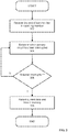
- FIG. 3 is a flow diagram illustrating an exemplary method of electronically detecting whether a bolt lock has been tampered with according to one embodiment.
- a first end of a bolt member is received in a receiving member.
- the first end of the bolt member can be specifically shaped for insertion into the receiving member, such that the bolt member can be locked in the receiving member upon or after insertion.
- a sensory circuit disposed within the receiving member can be adapted to electrically interface with a conductive medium running the axial length of the bolt member.
- one or more mating pins can electrically interface with a female pin connector through a pin connector opening at a first end of the bolt member.
- circuit When the circuit is connected to a power source, such as a battery, electrical current can then run from a first mating pin through the axial length of the bolt and back to a second mating pin in order to form a continuous circuit. If the circuit is severed (for example, the bolt is cut), the circuit can then detect an interruption (e.g., an open or short circuit). This condition can be checked continually or periodically according to various embodiments. Blocks 304 and 306 depict this process.
- a power source such as a battery
- the present date and time can be written to a local memory module.
- This data serves as evidence as to when the tamper event occurred.
- the data stored within this memory can subsequently be transmitted to an external device in response to a query transmitted from a wireless transceiver (e.g., an RFID interrogator) or over a serial bus cable.
- a wireless transceiver e.g., an RFID interrogator
- the memory of the bolt lock device can be written to as well. These write operations can be used, for example, in tracking a container as it is shipped through multiple locations and/or as the container is transferred between multiple parties. By periodically writing to the memory of the bolt lock device as the device changes locations and/or handling parties, a location log and date-stamp can be generated to facilitate more immediate discoveries of tamper events. In this manner, tamper events can be discovered well before the shipping container arrives at its intended destination.
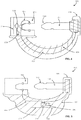
- FIG. 4 is a cross-sectional view of an exemplary bolt lock device with sensory circuit components disposed within the receiving member according to one embodiment.
- exemplary bolt lock device 400 can include a bolt member 102, a receiving member 202, and an encapsulant 402 connected to both the bolt member 102 and the receiving member 202.
- the receiving member 202 and the bolt member 102 are tethered to each other by the encapsulant 402.
- This has the further advantage that the bolt lock device 400 is a single unit rather than two parts which may become separated, lost, or accidentally switched with a similar component from a different bolt lock device 400.
- the components of the sensory circuit 206 are contained within the receiving member 202.
- This may include, for example, a transponder 210, an antenna 214, and one or more batteries 208.
- a serial bus interface e.g., USB, Firewire, RS-232, etc.
- transponder 210 and antenna 214 can be used in addition to or in lieu of transponder 210 and antenna 214 according to some embodiments.
- a portion of the electrical loop which detects tampering can be partly external to the bolt member 102 and the receiving member 202, formed within an encapsulating material.
- This encapsulant 402 can be made of flexible and durable material, such as certain plastics.
- a circuit wire 404 or other conductive medium can be routed from a part of the circuit 206 disposed within the receiving member 202 through the encapsulant 402 and connect electrically and/or mechanically with the second end 106 of the bolt member 102 (for example, it can connect with the head 108 of the bolt member 102, see FIG. 1A ).
- the bolt member 102 can have a solid interior according to some embodiments. This simplifies manufacture as the bolt member 102 does not require special processing in order to ensure that there is an adequate opening for a separate conductive medium. Instead, the structural portion of the bolt member 102 can itself serve to conduct electrical current in a single direction.
- an electrically conductive pathway can be formed from a first connecting pad (or pin) of the transponder 210, through an external wire 404 in the encapsulant 402, to the second end 106 of the bolt member 102, and return to a second connecting pad (or pin) of the transponder 210.
- Electrical continuity between the bolt member 102 and the second connecting pad (or pin) of the transponder 210 can be formed by a connection to a spring contact, or alternatively, to the lock retaining ring 204 (see FIG. 2 ) that is part of the receiving member 202.
- the transponder 210 can comprise a single chip, or a combination of chips and components forming a wireless communication means.
- the chip is an RFID chip operating in the UHF frequency band and complying with the ISO 18000-6C or EPC C1G2 standard.
- Other chips can also be applied, including those operating in the HF frequency band and compliant with ISO 14443A/B or ISO 15693, Bluetooth, Zigbee, or proprietary technologies.
- FIG. 5 is a cross-sectional view of an exemplary bolt lock device with sensory circuit components disposed within the encapsulant according to one embodiment.
- exemplary bolt lock device 500 can be structured and arranged similarly to exemplary bolt lock device 400 of FIG. 4 , except that the components of the circuit 206 (e.g., the transponder 210, the battery 208, and the antenna 214) can be disposed within the flexible "tether" encapsulant 402 which connects the receiving member 202 to the bolt member 102.
- This configuration can simplify the construction and assembly of the receiving member 202, as it is significantly easier to place the transponder 210, antenna 214, battery 208, and connections to the loop wire 404 in the encapsulant 402 than to assemble the components in the body of the receiving member 202.
- These circuit components can be made flexible or rigid as required, preassembled onto a substrate, and encapsulated as a unit according to some embodiments. A number of methods for encapsulation may be used for this purpose (for example, over-molding).
Landscapes
- Engineering & Computer Science (AREA)
- Physics & Mathematics (AREA)
- General Physics & Mathematics (AREA)
- Theoretical Computer Science (AREA)
- Computer Security & Cryptography (AREA)
- Microelectronics & Electronic Packaging (AREA)
- Mechanical Engineering (AREA)
- Computer Hardware Design (AREA)
- Lock And Its Accessories (AREA)
- Closures For Containers (AREA)
Claims (16)
- Riegelschlossvorrichtung, umfassend:ein Riegelglied (102);ein Aufnahmeglied (202), das eine Struktur zum Aufnehmen eines ersten Endes (104) des Riegelglieds umfasst;ein Anbindeglied (402), das mit dem Aufnahmeglied (202) und mit dem Riegelglied (102) verbunden ist, wobei das Anbindeglied ein leitfähiges Medium (110) umfasst, wobei, wenn das erste Ende (104) des Riegelglieds (102) in dem Aufnahmeglied (202) aufgenommen wurde, ein elektrisch leitender Weg von dem leitfähigen Medium durch mindestens einen Abschnitt des Riegelglieds (102) und mindestens einen Abschnitt des Aufnahmeglieds (202) gebildet wird; undeinen sensorischen Kreis (206), der in dem Aufnahmeglied (102) angeordnet ist, wobei der sensorische Kreis (206) einen Speicher umfasst,wobei der sensorische Kreis (206) betreibbar ist, um elektrischen Strom durch den elektrisch leitenden Weg zu übertragen, um so zu detektieren, ob der Kreis unterbrochen wurde,wobei der sensorische Kreis (206) ferner betreibbar ist, um im Fall einer detektierten Unterbrechung das aktuelle Datum und die aktuelle Uhrzeit in dem Speicher aufzuzeichnen.
- Riegelschlossvorrichtung nach Anspruch 1, wobei das Riegelglied Metall umfasst.
- Riegelschlossvorrichtung nach Anspruch 1, wobei:(i) das leitfähige Medium (110) elektrische Verdrahtung umfasst; und/oder(ii) das Anbindeglied (402) Kunststoff umfasst.
- Riegelschlossvorrichtung nach Anspruch 1, wobei ein zweites Ende (106) des Riegelglieds (102) einen elektrisch leitfähigen Kopf mit einem Durchmesser, der größer als der Durchmesser des Rests des Riegelglieds ist, umfasst.
- Riegelschlossvorrichtung nach Anspruch 4, wobei das leitfähige Medium (110) dazu ausgebildet ist, mit dem leitfähigen Kopf (106) elektrisch verbunden zu sein.
- Riegelschlossvorrichtung nach Anspruch 1, wobei der sensorische Kreis (206) ferner eine serielle Busverbindung umfasst.
- Riegelschlossvorrichtung nach Anspruch 1, wobei:(i) der sensorische Kreis (206) ferner einen Transponder, eine Antenne und eine Batterie umfasst; oder(ii) der sensorische Kreis ferner einen Transponder, der einen RFID-Chip umfasst, eine Antenne und eine Batterie umfasst.
- Riegelschlossvorrichtung nach Anspruch 7, wobei die Batterie eine Zellenbatterie umfasst oder wobei die Batterie eine Dünnschichtbatterie umfasst.
- Riegelschlossvorrichtung nach Anspruch 7, wobei die Batterie nur dann elektrisch mit dem sensorischen Kreis (206) verbunden ist, wenn das erste Ende (104) des Riegelglieds (102) in dem Aufnahmeglied (202) aufgenommen wurde.
- Riegelschlossvorrichtung nach einem beliebigen vorhergehenden Anspruch, wobei der sensorische Kreis ferner dazu ausgebildet ist, in dem Speicher eine Uhrzeit und einen Ort aufzuzeichnen.
- Verfahren zum elektronischen Detektieren, ob eine Riegelschlossvorrichtung nach Anspruch 1 manipuliert wurde, wobei das Verfahren umfasst:Aufnehmen eines ersten Endes des Riegelglieds (102) in dem Aufnahmeglied (202), wobei das Aufnahmeglied (202) mit dem Riegelglied (102) über das Anbindeglied (402) verbunden ist, das ein leitfähiges Medium (110) umfasst, wobei, wenn das erste Ende des Riegelglieds (102) in dem Aufnahmeglied (202) aufgenommen wurde, ein elektrisch leitender Weg von dem leitfähigen Medium (110) durch mindestens einen Abschnitt des Riegelglieds (102) und mindestens einen Abschnitt des Aufnahmeglieds (202) gebildet wird;Übertragen durch den sensorischen Kreis (206), der in dem Aufnahmeglied angeordnet ist, eines elektrischen Stroms durch den elektrisch leitenden Weg;Detektieren, ob der sensorische Kreis (206) unterbrochen wurde; und,im Fall einer detektierten Unterbrechung, Aufzeichnen des aktuellen Datums und der aktuellen Uhrzeit in dem Speicher.
- Verfahren nach Anspruch 11, ferner umfassend:Empfangen einer Anforderung von einer externen Vorrichtung, um Speicherinhalt zu lesen; und,als Antwort auf die Anforderung, Übertragen von Daten, die das aufgezeichnete Datum und die aufgezeichnete Uhrzeit angeben, an die externe Vorrichtung.
- Verfahren nach Anspruch 12, wobei Übertragen von Daten, die das aufgezeichnete Datum und die aufgezeichnete Uhrzeit angeben, an die externe Vorrichtung ferner drahtloses Übertragen von Daten, die das aufgezeichnete Datum und die aufgezeichnete Uhrzeit angeben, an die externe Vorrichtung umfasst.
- Verfahren nach Anspruch 12, wobei Übertragen von Daten, die das aufgezeichnete Datum und die aufgezeichnete Uhrzeit angeben, an die externe Vorrichtung ferner Übertragen von Daten, die das aufgezeichnete Datum und die aufgezeichnete Uhrzeit angeben, an die externe Vorrichtung über ein serielles Buskabel umfasst.
- Verfahren nach Anspruch 11, ferner umfassend:Empfangen einer Anforderung von einer externen Vorrichtung, um Daten auf einen Speicher zu schreiben;als Antwort auf die Anforderung, Schreiben der Daten auf den Speicher.
- Verfahren nach Anspruch 15, wobei die Daten einen Ort und ein Datum umfassen.
Applications Claiming Priority (2)
| Application Number | Priority Date | Filing Date | Title |
|---|---|---|---|
| US201261612906P | 2012-03-19 | 2012-03-19 | |
| PCT/US2013/030035 WO2013142104A1 (en) | 2012-03-19 | 2013-03-08 | Tamper evident cargo container seal bolt lock |
Publications (3)
| Publication Number | Publication Date |
|---|---|
| EP2828455A1 EP2828455A1 (de) | 2015-01-28 |
| EP2828455A4 EP2828455A4 (de) | 2016-03-23 |
| EP2828455B1 true EP2828455B1 (de) | 2019-08-14 |
Family
ID=49223182
Family Applications (1)
| Application Number | Title | Priority Date | Filing Date |
|---|---|---|---|
| EP13764844.0A Active EP2828455B1 (de) | 2012-03-19 | 2013-03-08 | Manipulationssicheres riegelschloss zum verschliessen eines frachtbehälters |
Country Status (5)
| Country | Link |
|---|---|
| US (4) | US9121195B2 (de) |
| EP (1) | EP2828455B1 (de) |
| CA (1) | CA2867133A1 (de) |
| MX (1) | MX351492B (de) |
| WO (1) | WO2013142104A1 (de) |
Families Citing this family (22)
| Publication number | Priority date | Publication date | Assignee | Title |
|---|---|---|---|---|
| US8963712B2 (en) | 2012-03-09 | 2015-02-24 | Neology, Inc. | Tamper evident cargo container seal bolt lock |
| MX351492B (es) | 2012-03-19 | 2017-10-18 | Neology Inc | Seguro de perno sensible a la manipulacion para contenedor de carga. |
| EP2743864A1 (de) * | 2012-12-17 | 2014-06-18 | Nafith Logistics Psc. | Sichere Dichtungsvorrichtung und Verfahren |
| CN105155928A (zh) * | 2015-06-17 | 2015-12-16 | 安徽中铁施封锁有限公司 | 一种安全施封锁 |
| CN104989183A (zh) * | 2015-06-17 | 2015-10-21 | 安徽中铁施封锁有限公司 | 一种新型施封锁 |
| CN105178720A (zh) * | 2015-06-17 | 2015-12-23 | 安徽中铁施封锁有限公司 | 一种施封锁 |
| CN105109449B (zh) * | 2015-08-20 | 2017-11-07 | 北京天润和创科技股份有限公司 | 一种多功能物流数字锁 |
| EP3206211A1 (de) * | 2016-02-15 | 2017-08-16 | The European Atomic Energy Community (EURATOM), represented by the European Commission | Siegelbolzen und verfahren zur installation des siegelgbolzen |
| ITUA20162059A1 (it) * | 2016-03-07 | 2017-09-07 | Luciano Grapsa | Sigillo di sicurezza autobloccante |
| US10210448B2 (en) | 2016-05-13 | 2019-02-19 | Xerox Corporation | Chipless radio frequency identification (RFIT) for tamper evidence |
| US10444805B1 (en) * | 2016-11-23 | 2019-10-15 | Amazon Technologies, Inc. | Tamper-evident brace for juncture of case pieces |
| US10276006B1 (en) * | 2017-12-02 | 2019-04-30 | The Boeing Company | Wireless tamper device |
| GB2569155A (en) * | 2017-12-07 | 2019-06-12 | Sekura Global Llp | Security Tag |
| WO2019140292A1 (en) | 2018-01-11 | 2019-07-18 | Grove Geoffrey | Metal fastener with embedded rfid tag and method of production |
| CN108784859B (zh) * | 2018-03-19 | 2021-06-25 | 成都频泰医疗设备有限公司 | 具有直接佩戴型矫正器的牙齿矫正系统 |
| US10597903B2 (en) * | 2018-04-27 | 2020-03-24 | Andrew C. Reeves | Systems and methods of securing items and verifying the same |
| CN112219213A (zh) | 2018-06-01 | 2021-01-12 | 应力工程服务股份有限公司 | 用于监控、跟踪和追踪物流的系统和方法 |
| US11157789B2 (en) | 2019-02-18 | 2021-10-26 | Compx International Inc. | Medicinal dosage storage and method for combined electronic inventory data and access control |
| TWI671460B (zh) * | 2019-03-15 | 2019-09-11 | 陳誌權 | 防盜電子封條 |
| CN110094110B (zh) * | 2019-05-24 | 2020-11-17 | 尹文秋 | 一种封签锁管理装置及方法 |
| US11847940B2 (en) | 2021-04-23 | 2023-12-19 | J. J. Keller & Associates, Inc. | Bolt seal |
| US11773626B2 (en) * | 2022-02-15 | 2023-10-03 | Stress Engineering Services, Inc. | Systems and methods for facilitating logistics |
Citations (3)
| Publication number | Priority date | Publication date | Assignee | Title |
|---|---|---|---|---|
| US6069563A (en) * | 1996-03-05 | 2000-05-30 | Kadner; Steven P. | Seal system |
| US20070262850A1 (en) * | 2004-07-06 | 2007-11-15 | Tagmaster Ab | Electronic Security Seal |
| US20100253099A1 (en) * | 2006-02-27 | 2010-10-07 | Navatech Container Security Llc | Device and Method of Sealing a Freight Container |
Family Cites Families (42)
| Publication number | Priority date | Publication date | Assignee | Title |
|---|---|---|---|---|
| US3712655A (en) | 1970-11-16 | 1973-01-23 | Stoffel Steel Corp | Plastic seal |
| US3824540A (en) * | 1972-07-27 | 1974-07-16 | K Smith | Bicycle lock and alarm apparatus |
| US3810145A (en) | 1972-10-27 | 1974-05-07 | Oak Industries Inc | Door bolt with electric alarm |
| US5097253A (en) | 1989-01-06 | 1992-03-17 | Battelle Memorial Institute | Electronic security device |
| DE4019265C1 (de) * | 1990-06-16 | 1991-11-28 | Anatoli 3013 Barsinghausen De Stobbe | |
| ATE136674T1 (de) | 1991-12-19 | 1996-04-15 | Ake Gustafson | Sicherheitsverschliessvorrichtung |
| DE29521243U1 (de) | 1994-09-05 | 1996-10-31 | Permasign Ltd | Sicherheitsvorrichtung |
| US5836002A (en) | 1995-06-01 | 1998-11-10 | Morstein; Jason | Anti-theft device |
| IL119509A (en) | 1996-10-28 | 2000-02-17 | Hi G Tek Ltd | Electronic tag |
| DE29813738U1 (de) | 1997-09-09 | 1999-01-21 | Plettner Andreas | Vorrichtung zum manipulationssicheren Kennzeichnen von Gegenständen |
| EP0978812B1 (de) | 1998-08-03 | 2006-04-12 | Hi-G-Tek Ltd | Selbstsperrende Siegel |
| WO2000016284A1 (en) | 1998-09-11 | 2000-03-23 | Key-Trak, Inc. | Tamper detection and prevention for an object control and tracking system |
| US6265973B1 (en) | 1999-04-16 | 2001-07-24 | Transguard Industries, Inc. | Electronic security seal |
| GB9914711D0 (en) | 1999-06-23 | 1999-08-25 | Leck Michael J | Electronic seal,methods and security system |
| GB2368174A (en) | 2000-10-19 | 2002-04-24 | Encrypta Electronics Ltd | Security seal device with detatchable cable display indicating reopening |
| US20030011474A1 (en) | 2001-07-13 | 2003-01-16 | Ng Sing King | Circuit and method for electronic security seal |
| US6778083B2 (en) | 2002-08-27 | 2004-08-17 | Hi-G-Tek Ltd. | Electronic locking seal |
| US6753775B2 (en) * | 2002-08-27 | 2004-06-22 | Hi-G-Tek Ltd. | Smart container monitoring system |
| US7498938B2 (en) * | 2002-10-08 | 2009-03-03 | Henry B. Ulrich | Security intelligence tracking anti-terrorist system |
| US7042354B2 (en) | 2002-12-11 | 2006-05-09 | Hi-G-Tek Ltd. | Tamper-resistant electronic seal |
| ZA200402317B (en) | 2003-09-15 | 2004-10-07 | Andrew Gerald Lynn Brown | "A seal". |
| US7239238B2 (en) | 2004-03-30 | 2007-07-03 | E. J. Brooks Company | Electronic security seal |
| US20090280862A1 (en) | 2004-07-22 | 2009-11-12 | Stanton Concepts Inc. | Tool Operated Combination Lock |
| DE102004063487A1 (de) | 2004-12-23 | 2006-07-13 | Intec Holding Gmbh | Siegeleinrichtung |
| US20080276668A1 (en) * | 2005-06-03 | 2008-11-13 | Stachowiak Jr John Edward | Retained lock system and method |
| US7828342B2 (en) | 2005-07-29 | 2010-11-09 | Terahop Networks, Inc. | Reusable locking body, of bolt-type seal lock, having open-ended passageway and U-shaped bolt |
| US7438334B2 (en) | 2005-07-29 | 2008-10-21 | Terry Daniel J | Bolt-type seal lock |
| EP1949346B1 (de) * | 2005-11-15 | 2016-04-13 | E.J. Brooks Company | Elektronische plombe mit originalitätssicherung |
| SG133417A1 (en) | 2005-12-08 | 2007-07-30 | Brooks Asia Pte Ltd | A locking seal with tamper indication and notification device |
| US20070256615A1 (en) | 2006-01-17 | 2007-11-08 | David Delgrosso | System and method for unattended access to safe deposit boxes |
| CN2915758Y (zh) * | 2006-02-21 | 2007-06-27 | 硕学电子科技(上海)有限公司 | Uhf全向无源电子货柜锁 |
| US7543467B2 (en) * | 2006-09-19 | 2009-06-09 | Sheehan Thomas R | Portable lock wirelessly connectable to security system |
| US9472125B2 (en) * | 2007-10-05 | 2016-10-18 | E.J. Brooks Company | Reusable bolt electronic seal module with GPS/cellular phone communications and tracking system |
| US8031069B2 (en) | 2008-01-14 | 2011-10-04 | Oded Yair Cohn | Electronic security seal and system |
| TW200936866A (en) | 2008-02-26 | 2009-09-01 | Jin-Hao Chaocheng | RFID electronic lock |
| US8207848B2 (en) * | 2008-05-16 | 2012-06-26 | Google Inc. | Locking system for shipping container including bolt seal and electronic device with arms for receiving bolt seal |
| WO2009140669A2 (en) * | 2008-05-16 | 2009-11-19 | Terahop Networks, Inc. | Securing, monitoring and tracking shipping containers |
| KR20110032130A (ko) | 2009-09-22 | 2011-03-30 | 변지은 | 자전거용 도난 방지장치 |
| US8666664B2 (en) * | 2009-11-27 | 2014-03-04 | Syris Technology Corp. | Electronic seal |
| WO2013068036A1 (en) * | 2011-11-08 | 2013-05-16 | Sellmore Bv | Electromechanical lock for cabinets, showcases and drawers |
| US8963712B2 (en) | 2012-03-09 | 2015-02-24 | Neology, Inc. | Tamper evident cargo container seal bolt lock |
| MX351492B (es) * | 2012-03-19 | 2017-10-18 | Neology Inc | Seguro de perno sensible a la manipulacion para contenedor de carga. |
-
2013
- 2013-03-08 MX MX2014011244A patent/MX351492B/es active IP Right Grant
- 2013-03-08 CA CA 2867133 patent/CA2867133A1/en not_active Abandoned
- 2013-03-08 EP EP13764844.0A patent/EP2828455B1/de active Active
- 2013-03-08 WO PCT/US2013/030035 patent/WO2013142104A1/en active Application Filing
- 2013-03-08 US US13/791,630 patent/US9121195B2/en active Active
-
2015
- 2015-08-31 US US14/841,666 patent/US9624692B2/en active Active
-
2017
- 2017-03-24 US US15/468,588 patent/US10145146B2/en active Active
-
2018
- 2018-11-28 US US16/202,945 patent/US10689882B2/en active Active
Patent Citations (3)
| Publication number | Priority date | Publication date | Assignee | Title |
|---|---|---|---|---|
| US6069563A (en) * | 1996-03-05 | 2000-05-30 | Kadner; Steven P. | Seal system |
| US20070262850A1 (en) * | 2004-07-06 | 2007-11-15 | Tagmaster Ab | Electronic Security Seal |
| US20100253099A1 (en) * | 2006-02-27 | 2010-10-07 | Navatech Container Security Llc | Device and Method of Sealing a Freight Container |
Also Published As
| Publication number | Publication date |
|---|---|
| EP2828455A1 (de) | 2015-01-28 |
| US10145146B2 (en) | 2018-12-04 |
| US20170200401A1 (en) | 2017-07-13 |
| US20130255337A1 (en) | 2013-10-03 |
| WO2013142104A1 (en) | 2013-09-26 |
| US9121195B2 (en) | 2015-09-01 |
| MX2014011244A (es) | 2015-03-09 |
| EP2828455A4 (de) | 2016-03-23 |
| US20150368930A1 (en) | 2015-12-24 |
| US9624692B2 (en) | 2017-04-18 |
| US20190145129A1 (en) | 2019-05-16 |
| CA2867133A1 (en) | 2013-09-26 |
| MX351492B (es) | 2017-10-18 |
| US10689882B2 (en) | 2020-06-23 |
Similar Documents
| Publication | Publication Date | Title |
|---|---|---|
| US10689882B2 (en) | Tamper evident cargo container seal bolt lock | |
| US10815694B2 (en) | Tamper evident cargo container seal bolt lock | |
| US9745782B2 (en) | Secure sealing device and method | |
| US7828342B2 (en) | Reusable locking body, of bolt-type seal lock, having open-ended passageway and U-shaped bolt | |
| US7202788B2 (en) | RFID electronic seal and system using the RFID electronic seal | |
| US20080198011A1 (en) | Radio-frequency identification tags for preventing and detecting tampering | |
| EP2590154A1 (de) | Sicherheitssiegel | |
| CN115023705A (zh) | 包括无线电识别密封件的包装 | |
| EP3005246B1 (de) | Modular rfid system with passif rfid module and active rfid module | |
| US20190138874A1 (en) | Rfid-based indicator for use with fastening substrates and related methods | |
| US20090199606A1 (en) | Tamper evident seal | |
| US7612671B2 (en) | Attachment device, attachment receiving device and system for identifying secured containers | |
| WO2021015666A1 (en) | Electronic bolt seal |
Legal Events
| Date | Code | Title | Description |
|---|---|---|---|
| PUAI | Public reference made under article 153(3) epc to a published international application that has entered the european phase |
Free format text: ORIGINAL CODE: 0009012 |
|
| 17P | Request for examination filed |
Effective date: 20140917 |
|
| AK | Designated contracting states |
Kind code of ref document: A1 Designated state(s): AL AT BE BG CH CY CZ DE DK EE ES FI FR GB GR HR HU IE IS IT LI LT LU LV MC MK MT NL NO PL PT RO RS SE SI SK SM TR |
|
| AX | Request for extension of the european patent |
Extension state: BA ME |
|
| DAX | Request for extension of the european patent (deleted) | ||
| RA4 | Supplementary search report drawn up and despatched (corrected) |
Effective date: 20160224 |
|
| RIC1 | Information provided on ipc code assigned before grant |
Ipc: E05B 45/00 20060101ALI20160218BHEP Ipc: E05B 39/04 20060101AFI20160218BHEP |
|
| STAA | Information on the status of an ep patent application or granted ep patent |
Free format text: STATUS: EXAMINATION IS IN PROGRESS |
|
| 17Q | First examination report despatched |
Effective date: 20180214 |
|
| GRAP | Despatch of communication of intention to grant a patent |
Free format text: ORIGINAL CODE: EPIDOSNIGR1 |
|
| STAA | Information on the status of an ep patent application or granted ep patent |
Free format text: STATUS: GRANT OF PATENT IS INTENDED |
|
| INTG | Intention to grant announced |
Effective date: 20190307 |
|
| GRAS | Grant fee paid |
Free format text: ORIGINAL CODE: EPIDOSNIGR3 |
|
| GRAA | (expected) grant |
Free format text: ORIGINAL CODE: 0009210 |
|
| STAA | Information on the status of an ep patent application or granted ep patent |
Free format text: STATUS: THE PATENT HAS BEEN GRANTED |
|
| AK | Designated contracting states |
Kind code of ref document: B1 Designated state(s): AL AT BE BG CH CY CZ DE DK EE ES FI FR GB GR HR HU IE IS IT LI LT LU LV MC MK MT NL NO PL PT RO RS SE SI SK SM TR |
|
| REG | Reference to a national code |
Ref country code: GB Ref legal event code: FG4D |
|
| REG | Reference to a national code |
Ref country code: CH Ref legal event code: EP Ref country code: AT Ref legal event code: REF Ref document number: 1167221 Country of ref document: AT Kind code of ref document: T Effective date: 20190815 |
|
| REG | Reference to a national code |
Ref country code: IE Ref legal event code: FG4D |
|
| REG | Reference to a national code |
Ref country code: DE Ref legal event code: R096 Ref document number: 602013059159 Country of ref document: DE |
|
| REG | Reference to a national code |
Ref country code: NL Ref legal event code: MP Effective date: 20190814 |
|
| REG | Reference to a national code |
Ref country code: LT Ref legal event code: MG4D |
|
| PG25 | Lapsed in a contracting state [announced via postgrant information from national office to epo] |
Ref country code: LT Free format text: LAPSE BECAUSE OF FAILURE TO SUBMIT A TRANSLATION OF THE DESCRIPTION OR TO PAY THE FEE WITHIN THE PRESCRIBED TIME-LIMIT Effective date: 20190814 Ref country code: HR Free format text: LAPSE BECAUSE OF FAILURE TO SUBMIT A TRANSLATION OF THE DESCRIPTION OR TO PAY THE FEE WITHIN THE PRESCRIBED TIME-LIMIT Effective date: 20190814 Ref country code: NL Free format text: LAPSE BECAUSE OF FAILURE TO SUBMIT A TRANSLATION OF THE DESCRIPTION OR TO PAY THE FEE WITHIN THE PRESCRIBED TIME-LIMIT Effective date: 20190814 Ref country code: BG Free format text: LAPSE BECAUSE OF FAILURE TO SUBMIT A TRANSLATION OF THE DESCRIPTION OR TO PAY THE FEE WITHIN THE PRESCRIBED TIME-LIMIT Effective date: 20191114 Ref country code: PT Free format text: LAPSE BECAUSE OF FAILURE TO SUBMIT A TRANSLATION OF THE DESCRIPTION OR TO PAY THE FEE WITHIN THE PRESCRIBED TIME-LIMIT Effective date: 20191216 Ref country code: FI Free format text: LAPSE BECAUSE OF FAILURE TO SUBMIT A TRANSLATION OF THE DESCRIPTION OR TO PAY THE FEE WITHIN THE PRESCRIBED TIME-LIMIT Effective date: 20190814 Ref country code: NO Free format text: LAPSE BECAUSE OF FAILURE TO SUBMIT A TRANSLATION OF THE DESCRIPTION OR TO PAY THE FEE WITHIN THE PRESCRIBED TIME-LIMIT Effective date: 20191114 Ref country code: SE Free format text: LAPSE BECAUSE OF FAILURE TO SUBMIT A TRANSLATION OF THE DESCRIPTION OR TO PAY THE FEE WITHIN THE PRESCRIBED TIME-LIMIT Effective date: 20190814 |
|
| REG | Reference to a national code |
Ref country code: AT Ref legal event code: MK05 Ref document number: 1167221 Country of ref document: AT Kind code of ref document: T Effective date: 20190814 |
|
| PG25 | Lapsed in a contracting state [announced via postgrant information from national office to epo] |
Ref country code: RS Free format text: LAPSE BECAUSE OF FAILURE TO SUBMIT A TRANSLATION OF THE DESCRIPTION OR TO PAY THE FEE WITHIN THE PRESCRIBED TIME-LIMIT Effective date: 20190814 Ref country code: IS Free format text: LAPSE BECAUSE OF FAILURE TO SUBMIT A TRANSLATION OF THE DESCRIPTION OR TO PAY THE FEE WITHIN THE PRESCRIBED TIME-LIMIT Effective date: 20191214 Ref country code: GR Free format text: LAPSE BECAUSE OF FAILURE TO SUBMIT A TRANSLATION OF THE DESCRIPTION OR TO PAY THE FEE WITHIN THE PRESCRIBED TIME-LIMIT Effective date: 20191115 Ref country code: ES Free format text: LAPSE BECAUSE OF FAILURE TO SUBMIT A TRANSLATION OF THE DESCRIPTION OR TO PAY THE FEE WITHIN THE PRESCRIBED TIME-LIMIT Effective date: 20190814 Ref country code: AL Free format text: LAPSE BECAUSE OF FAILURE TO SUBMIT A TRANSLATION OF THE DESCRIPTION OR TO PAY THE FEE WITHIN THE PRESCRIBED TIME-LIMIT Effective date: 20190814 Ref country code: LV Free format text: LAPSE BECAUSE OF FAILURE TO SUBMIT A TRANSLATION OF THE DESCRIPTION OR TO PAY THE FEE WITHIN THE PRESCRIBED TIME-LIMIT Effective date: 20190814 |
|
| PG25 | Lapsed in a contracting state [announced via postgrant information from national office to epo] |
Ref country code: TR Free format text: LAPSE BECAUSE OF FAILURE TO SUBMIT A TRANSLATION OF THE DESCRIPTION OR TO PAY THE FEE WITHIN THE PRESCRIBED TIME-LIMIT Effective date: 20190814 |
|
| PG25 | Lapsed in a contracting state [announced via postgrant information from national office to epo] |
Ref country code: AT Free format text: LAPSE BECAUSE OF FAILURE TO SUBMIT A TRANSLATION OF THE DESCRIPTION OR TO PAY THE FEE WITHIN THE PRESCRIBED TIME-LIMIT Effective date: 20190814 Ref country code: EE Free format text: LAPSE BECAUSE OF FAILURE TO SUBMIT A TRANSLATION OF THE DESCRIPTION OR TO PAY THE FEE WITHIN THE PRESCRIBED TIME-LIMIT Effective date: 20190814 Ref country code: DK Free format text: LAPSE BECAUSE OF FAILURE TO SUBMIT A TRANSLATION OF THE DESCRIPTION OR TO PAY THE FEE WITHIN THE PRESCRIBED TIME-LIMIT Effective date: 20190814 Ref country code: RO Free format text: LAPSE BECAUSE OF FAILURE TO SUBMIT A TRANSLATION OF THE DESCRIPTION OR TO PAY THE FEE WITHIN THE PRESCRIBED TIME-LIMIT Effective date: 20190814 Ref country code: IT Free format text: LAPSE BECAUSE OF FAILURE TO SUBMIT A TRANSLATION OF THE DESCRIPTION OR TO PAY THE FEE WITHIN THE PRESCRIBED TIME-LIMIT Effective date: 20190814 Ref country code: PL Free format text: LAPSE BECAUSE OF FAILURE TO SUBMIT A TRANSLATION OF THE DESCRIPTION OR TO PAY THE FEE WITHIN THE PRESCRIBED TIME-LIMIT Effective date: 20190814 |
|
| PG25 | Lapsed in a contracting state [announced via postgrant information from national office to epo] |
Ref country code: SM Free format text: LAPSE BECAUSE OF FAILURE TO SUBMIT A TRANSLATION OF THE DESCRIPTION OR TO PAY THE FEE WITHIN THE PRESCRIBED TIME-LIMIT Effective date: 20190814 Ref country code: IS Free format text: LAPSE BECAUSE OF FAILURE TO SUBMIT A TRANSLATION OF THE DESCRIPTION OR TO PAY THE FEE WITHIN THE PRESCRIBED TIME-LIMIT Effective date: 20200224 Ref country code: SK Free format text: LAPSE BECAUSE OF FAILURE TO SUBMIT A TRANSLATION OF THE DESCRIPTION OR TO PAY THE FEE WITHIN THE PRESCRIBED TIME-LIMIT Effective date: 20190814 Ref country code: CZ Free format text: LAPSE BECAUSE OF FAILURE TO SUBMIT A TRANSLATION OF THE DESCRIPTION OR TO PAY THE FEE WITHIN THE PRESCRIBED TIME-LIMIT Effective date: 20190814 |
|
| REG | Reference to a national code |
Ref country code: DE Ref legal event code: R097 Ref document number: 602013059159 Country of ref document: DE |
|
| PLBE | No opposition filed within time limit |
Free format text: ORIGINAL CODE: 0009261 |
|
| STAA | Information on the status of an ep patent application or granted ep patent |
Free format text: STATUS: NO OPPOSITION FILED WITHIN TIME LIMIT |
|
| PG2D | Information on lapse in contracting state deleted |
Ref country code: IS |
|
| 26N | No opposition filed |
Effective date: 20200603 |
|
| PG25 | Lapsed in a contracting state [announced via postgrant information from national office to epo] |
Ref country code: SI Free format text: LAPSE BECAUSE OF FAILURE TO SUBMIT A TRANSLATION OF THE DESCRIPTION OR TO PAY THE FEE WITHIN THE PRESCRIBED TIME-LIMIT Effective date: 20190814 |
|
| PG25 | Lapsed in a contracting state [announced via postgrant information from national office to epo] |
Ref country code: MC Free format text: LAPSE BECAUSE OF FAILURE TO SUBMIT A TRANSLATION OF THE DESCRIPTION OR TO PAY THE FEE WITHIN THE PRESCRIBED TIME-LIMIT Effective date: 20190814 |
|
| REG | Reference to a national code |
Ref country code: CH Ref legal event code: PL |
|
| REG | Reference to a national code |
Ref country code: BE Ref legal event code: MM Effective date: 20200331 |
|
| PG25 | Lapsed in a contracting state [announced via postgrant information from national office to epo] |
Ref country code: LU Free format text: LAPSE BECAUSE OF NON-PAYMENT OF DUE FEES Effective date: 20200308 |
|
| PG25 | Lapsed in a contracting state [announced via postgrant information from national office to epo] |
Ref country code: LI Free format text: LAPSE BECAUSE OF NON-PAYMENT OF DUE FEES Effective date: 20200331 Ref country code: IE Free format text: LAPSE BECAUSE OF NON-PAYMENT OF DUE FEES Effective date: 20200308 Ref country code: CH Free format text: LAPSE BECAUSE OF NON-PAYMENT OF DUE FEES Effective date: 20200331 |
|
| PG25 | Lapsed in a contracting state [announced via postgrant information from national office to epo] |
Ref country code: BE Free format text: LAPSE BECAUSE OF NON-PAYMENT OF DUE FEES Effective date: 20200331 |
|
| PG25 | Lapsed in a contracting state [announced via postgrant information from national office to epo] |
Ref country code: MT Free format text: LAPSE BECAUSE OF FAILURE TO SUBMIT A TRANSLATION OF THE DESCRIPTION OR TO PAY THE FEE WITHIN THE PRESCRIBED TIME-LIMIT Effective date: 20190814 Ref country code: CY Free format text: LAPSE BECAUSE OF FAILURE TO SUBMIT A TRANSLATION OF THE DESCRIPTION OR TO PAY THE FEE WITHIN THE PRESCRIBED TIME-LIMIT Effective date: 20190814 |
|
| PG25 | Lapsed in a contracting state [announced via postgrant information from national office to epo] |
Ref country code: MK Free format text: LAPSE BECAUSE OF FAILURE TO SUBMIT A TRANSLATION OF THE DESCRIPTION OR TO PAY THE FEE WITHIN THE PRESCRIBED TIME-LIMIT Effective date: 20190814 |
|
| PGFP | Annual fee paid to national office [announced via postgrant information from national office to epo] |
Ref country code: FR Payment date: 20230123 Year of fee payment: 11 |
|
| PGFP | Annual fee paid to national office [announced via postgrant information from national office to epo] |
Ref country code: GB Payment date: 20230119 Year of fee payment: 11 Ref country code: DE Payment date: 20230117 Year of fee payment: 11 |