EP2828226B1 - Modular installation for the manufacture of an explosive emulsion precursor - Google Patents
Modular installation for the manufacture of an explosive emulsion precursor Download PDFInfo
- Publication number
- EP2828226B1 EP2828226B1 EP14703120.7A EP14703120A EP2828226B1 EP 2828226 B1 EP2828226 B1 EP 2828226B1 EP 14703120 A EP14703120 A EP 14703120A EP 2828226 B1 EP2828226 B1 EP 2828226B1
- Authority
- EP
- European Patent Office
- Prior art keywords
- tank
- container
- emulsion
- oily phase
- aqueous phase
- Prior art date
- Legal status (The legal status is an assumption and is not a legal conclusion. Google has not performed a legal analysis and makes no representation as to the accuracy of the status listed.)
- Active
Links
- 239000000839 emulsion Substances 0.000 title claims description 127
- 238000009434 installation Methods 0.000 title claims description 67
- 238000004519 manufacturing process Methods 0.000 title claims description 22
- 239000002360 explosive Substances 0.000 title claims description 20
- 239000002243 precursor Substances 0.000 title claims description 13
- 239000012071 phase Substances 0.000 claims description 152
- 239000008346 aqueous phase Substances 0.000 claims description 84
- 238000002360 preparation method Methods 0.000 claims description 54
- 238000002156 mixing Methods 0.000 claims description 32
- XLYOFNOQVPJJNP-UHFFFAOYSA-N water Substances O XLYOFNOQVPJJNP-UHFFFAOYSA-N 0.000 claims description 32
- 239000013529 heat transfer fluid Substances 0.000 claims description 31
- 238000010438 heat treatment Methods 0.000 claims description 28
- 238000003860 storage Methods 0.000 claims description 26
- 238000005086 pumping Methods 0.000 claims description 25
- 239000012530 fluid Substances 0.000 claims description 21
- 239000004094 surface-active agent Substances 0.000 claims description 19
- 229910002651 NO3 Inorganic materials 0.000 claims description 17
- NHNBFGGVMKEFGY-UHFFFAOYSA-N Nitrate Chemical compound [O-][N+]([O-])=O NHNBFGGVMKEFGY-UHFFFAOYSA-N 0.000 claims description 17
- 238000003756 stirring Methods 0.000 claims description 16
- 238000004090 dissolution Methods 0.000 claims description 15
- 239000000872 buffer Substances 0.000 claims description 14
- 238000000034 method Methods 0.000 claims description 13
- 150000002823 nitrates Chemical class 0.000 claims description 11
- 238000004458 analytical method Methods 0.000 claims description 6
- 238000011049 filling Methods 0.000 claims description 6
- 235000013311 vegetables Nutrition 0.000 claims description 4
- 229910052500 inorganic mineral Inorganic materials 0.000 claims description 3
- 239000011707 mineral Substances 0.000 claims description 3
- 230000000087 stabilizing effect Effects 0.000 claims description 3
- 239000007788 liquid Substances 0.000 claims description 2
- 238000010079 rubber tapping Methods 0.000 claims 1
- 239000003921 oil Substances 0.000 description 22
- 239000000203 mixture Substances 0.000 description 11
- 238000001816 cooling Methods 0.000 description 10
- 238000013019 agitation Methods 0.000 description 8
- 238000010008 shearing Methods 0.000 description 7
- 239000003795 chemical substances by application Substances 0.000 description 6
- 239000000295 fuel oil Substances 0.000 description 6
- 239000008187 granular material Substances 0.000 description 6
- 230000008569 process Effects 0.000 description 6
- 239000000446 fuel Substances 0.000 description 5
- 239000007800 oxidant agent Substances 0.000 description 5
- 230000001590 oxidative effect Effects 0.000 description 5
- 239000000654 additive Substances 0.000 description 4
- 230000008901 benefit Effects 0.000 description 4
- 238000000926 separation method Methods 0.000 description 4
- 238000007599 discharging Methods 0.000 description 3
- 239000002480 mineral oil Substances 0.000 description 3
- 239000000047 product Substances 0.000 description 3
- 239000002994 raw material Substances 0.000 description 3
- 238000011084 recovery Methods 0.000 description 3
- LPXPTNMVRIOKMN-UHFFFAOYSA-M sodium nitrite Chemical compound [Na+].[O-]N=O LPXPTNMVRIOKMN-UHFFFAOYSA-M 0.000 description 3
- PAWQVTBBRAZDMG-UHFFFAOYSA-N 2-(3-bromo-2-fluorophenyl)acetic acid Chemical compound OC(=O)CC1=CC=CC(Br)=C1F PAWQVTBBRAZDMG-UHFFFAOYSA-N 0.000 description 2
- DGAQECJNVWCQMB-PUAWFVPOSA-M Ilexoside XXIX Chemical compound C[C@@H]1CC[C@@]2(CC[C@@]3(C(=CC[C@H]4[C@]3(CC[C@@H]5[C@@]4(CC[C@@H](C5(C)C)OS(=O)(=O)[O-])C)C)[C@@H]2[C@]1(C)O)C)C(=O)O[C@H]6[C@@H]([C@H]([C@@H]([C@H](O6)CO)O)O)O.[Na+] DGAQECJNVWCQMB-PUAWFVPOSA-M 0.000 description 2
- 229910000831 Steel Inorganic materials 0.000 description 2
- 230000009471 action Effects 0.000 description 2
- 238000007792 addition Methods 0.000 description 2
- 238000004891 communication Methods 0.000 description 2
- 230000001276 controlling effect Effects 0.000 description 2
- 230000005611 electricity Effects 0.000 description 2
- 238000012423 maintenance Methods 0.000 description 2
- 238000007726 management method Methods 0.000 description 2
- 238000005457 optimization Methods 0.000 description 2
- 239000010690 paraffinic oil Substances 0.000 description 2
- 238000003908 quality control method Methods 0.000 description 2
- 230000001105 regulatory effect Effects 0.000 description 2
- 239000011734 sodium Substances 0.000 description 2
- 229910052708 sodium Inorganic materials 0.000 description 2
- 239000010959 steel Substances 0.000 description 2
- UMGDCJDMYOKAJW-UHFFFAOYSA-N thiourea Chemical compound NC(N)=S UMGDCJDMYOKAJW-UHFFFAOYSA-N 0.000 description 2
- 208000031968 Cadaver Diseases 0.000 description 1
- OYPRJOBELJOOCE-UHFFFAOYSA-N Calcium Chemical compound [Ca] OYPRJOBELJOOCE-UHFFFAOYSA-N 0.000 description 1
- 241001080024 Telles Species 0.000 description 1
- XSQUKJJJFZCRTK-UHFFFAOYSA-N Urea Natural products NC(N)=O XSQUKJJJFZCRTK-UHFFFAOYSA-N 0.000 description 1
- 241001639412 Verres Species 0.000 description 1
- 239000002253 acid Substances 0.000 description 1
- 230000000996 additive effect Effects 0.000 description 1
- DVARTQFDIMZBAA-UHFFFAOYSA-O ammonium nitrate Chemical class [NH4+].[O-][N+]([O-])=O DVARTQFDIMZBAA-UHFFFAOYSA-O 0.000 description 1
- 230000003416 augmentation Effects 0.000 description 1
- 230000004888 barrier function Effects 0.000 description 1
- 239000011575 calcium Substances 0.000 description 1
- 229910052791 calcium Inorganic materials 0.000 description 1
- ZCCIPPOKBCJFDN-UHFFFAOYSA-N calcium nitrate Chemical class [Ca+2].[O-][N+]([O-])=O.[O-][N+]([O-])=O ZCCIPPOKBCJFDN-UHFFFAOYSA-N 0.000 description 1
- 239000003153 chemical reaction reagent Substances 0.000 description 1
- 230000000295 complement effect Effects 0.000 description 1
- 238000010924 continuous production Methods 0.000 description 1
- 239000002826 coolant Substances 0.000 description 1
- 238000002425 crystallisation Methods 0.000 description 1
- 230000008025 crystallization Effects 0.000 description 1
- 238000009826 distribution Methods 0.000 description 1
- 230000000694 effects Effects 0.000 description 1
- 238000010616 electrical installation Methods 0.000 description 1
- 229940082150 encore Drugs 0.000 description 1
- 239000003925 fat Substances 0.000 description 1
- 239000012467 final product Substances 0.000 description 1
- 238000002309 gasification Methods 0.000 description 1
- 239000011521 glass Substances 0.000 description 1
- 238000002513 implantation Methods 0.000 description 1
- 230000006872 improvement Effects 0.000 description 1
- 238000011065 in-situ storage Methods 0.000 description 1
- 238000009830 intercalation Methods 0.000 description 1
- 230000002687 intercalation Effects 0.000 description 1
- 239000004005 microsphere Substances 0.000 description 1
- 235000010446 mineral oil Nutrition 0.000 description 1
- 238000005192 partition Methods 0.000 description 1
- 230000000704 physical effect Effects 0.000 description 1
- 230000001737 promoting effect Effects 0.000 description 1
- 230000009467 reduction Effects 0.000 description 1
- 238000005070 sampling Methods 0.000 description 1
- 230000001235 sensitizing effect Effects 0.000 description 1
- 235000010288 sodium nitrite Nutrition 0.000 description 1
- VGTPCRGMBIAPIM-UHFFFAOYSA-M sodium thiocyanate Chemical compound [Na+].[S-]C#N VGTPCRGMBIAPIM-UHFFFAOYSA-M 0.000 description 1
- 239000007787 solid Substances 0.000 description 1
- 230000006641 stabilisation Effects 0.000 description 1
- 239000012536 storage buffer Substances 0.000 description 1
- 239000000126 substance Substances 0.000 description 1
- 239000008400 supply water Substances 0.000 description 1
- 239000008158 vegetable oil Substances 0.000 description 1
- 230000000007 visual effect Effects 0.000 description 1
- 239000011800 void material Substances 0.000 description 1
- 230000003313 weakening effect Effects 0.000 description 1
Images


Classifications
-
- C—CHEMISTRY; METALLURGY
- C06—EXPLOSIVES; MATCHES
- C06B—EXPLOSIVES OR THERMIC COMPOSITIONS; MANUFACTURE THEREOF; USE OF SINGLE SUBSTANCES AS EXPLOSIVES
- C06B21/00—Apparatus or methods for working-up explosives, e.g. forming, cutting, drying
- C06B21/0008—Compounding the ingredient
-
- C—CHEMISTRY; METALLURGY
- C06—EXPLOSIVES; MATCHES
- C06B—EXPLOSIVES OR THERMIC COMPOSITIONS; MANUFACTURE THEREOF; USE OF SINGLE SUBSTANCES AS EXPLOSIVES
- C06B47/00—Compositions in which the components are separately stored until the moment of burning or explosion, e.g. "Sprengel"-type explosives; Suspensions of solid component in a normally non-explosive liquid phase, including a thickened aqueous phase
- C06B47/14—Compositions in which the components are separately stored until the moment of burning or explosion, e.g. "Sprengel"-type explosives; Suspensions of solid component in a normally non-explosive liquid phase, including a thickened aqueous phase comprising a solid component and an aqueous phase
-
- B—PERFORMING OPERATIONS; TRANSPORTING
- B01—PHYSICAL OR CHEMICAL PROCESSES OR APPARATUS IN GENERAL
- B01F—MIXING, e.g. DISSOLVING, EMULSIFYING OR DISPERSING
- B01F21/00—Dissolving
- B01F21/10—Dissolving using driven stirrers
-
- B—PERFORMING OPERATIONS; TRANSPORTING
- B01—PHYSICAL OR CHEMICAL PROCESSES OR APPARATUS IN GENERAL
- B01F—MIXING, e.g. DISSOLVING, EMULSIFYING OR DISPERSING
- B01F23/00—Mixing according to the phases to be mixed, e.g. dispersing or emulsifying
- B01F23/40—Mixing liquids with liquids; Emulsifying
- B01F23/41—Emulsifying
- B01F23/411—Emulsifying using electrical or magnetic fields, heat or vibrations
-
- B—PERFORMING OPERATIONS; TRANSPORTING
- B01—PHYSICAL OR CHEMICAL PROCESSES OR APPARATUS IN GENERAL
- B01F—MIXING, e.g. DISSOLVING, EMULSIFYING OR DISPERSING
- B01F27/00—Mixers with rotary stirring devices in fixed receptacles; Kneaders
- B01F27/05—Stirrers
- B01F27/11—Stirrers characterised by the configuration of the stirrers
- B01F27/19—Stirrers with two or more mixing elements mounted in sequence on the same axis
- B01F27/192—Stirrers with two or more mixing elements mounted in sequence on the same axis with dissimilar elements
-
- B—PERFORMING OPERATIONS; TRANSPORTING
- B01—PHYSICAL OR CHEMICAL PROCESSES OR APPARATUS IN GENERAL
- B01F—MIXING, e.g. DISSOLVING, EMULSIFYING OR DISPERSING
- B01F27/00—Mixers with rotary stirring devices in fixed receptacles; Kneaders
- B01F27/80—Mixers with rotary stirring devices in fixed receptacles; Kneaders with stirrers rotating about a substantially vertical axis
- B01F27/85—Mixers with rotary stirring devices in fixed receptacles; Kneaders with stirrers rotating about a substantially vertical axis with two or more stirrers on separate shafts
-
- B—PERFORMING OPERATIONS; TRANSPORTING
- B01—PHYSICAL OR CHEMICAL PROCESSES OR APPARATUS IN GENERAL
- B01F—MIXING, e.g. DISSOLVING, EMULSIFYING OR DISPERSING
- B01F27/00—Mixers with rotary stirring devices in fixed receptacles; Kneaders
- B01F27/80—Mixers with rotary stirring devices in fixed receptacles; Kneaders with stirrers rotating about a substantially vertical axis
- B01F27/90—Mixers with rotary stirring devices in fixed receptacles; Kneaders with stirrers rotating about a substantially vertical axis with paddles or arms
-
- B—PERFORMING OPERATIONS; TRANSPORTING
- B01—PHYSICAL OR CHEMICAL PROCESSES OR APPARATUS IN GENERAL
- B01F—MIXING, e.g. DISSOLVING, EMULSIFYING OR DISPERSING
- B01F33/00—Other mixers; Mixing plants; Combinations of mixers
- B01F33/50—Movable or transportable mixing devices or plants
- B01F33/501—Movable mixing devices, i.e. readily shifted or displaced from one place to another, e.g. portable during use
- B01F33/5013—Movable mixing devices, i.e. readily shifted or displaced from one place to another, e.g. portable during use movable by mechanical means, e.g. hoisting systems, grippers or lift trucks
-
- B—PERFORMING OPERATIONS; TRANSPORTING
- B01—PHYSICAL OR CHEMICAL PROCESSES OR APPARATUS IN GENERAL
- B01F—MIXING, e.g. DISSOLVING, EMULSIFYING OR DISPERSING
- B01F35/00—Accessories for mixers; Auxiliary operations or auxiliary devices; Parts or details of general application
- B01F35/90—Heating or cooling systems
- B01F35/93—Heating or cooling systems arranged inside the receptacle
-
- C—CHEMISTRY; METALLURGY
- C06—EXPLOSIVES; MATCHES
- C06B—EXPLOSIVES OR THERMIC COMPOSITIONS; MANUFACTURE THEREOF; USE OF SINGLE SUBSTANCES AS EXPLOSIVES
- C06B31/00—Compositions containing an inorganic nitrogen-oxygen salt
-
- C—CHEMISTRY; METALLURGY
- C06—EXPLOSIVES; MATCHES
- C06B—EXPLOSIVES OR THERMIC COMPOSITIONS; MANUFACTURE THEREOF; USE OF SINGLE SUBSTANCES AS EXPLOSIVES
- C06B47/00—Compositions in which the components are separately stored until the moment of burning or explosion, e.g. "Sprengel"-type explosives; Suspensions of solid component in a normally non-explosive liquid phase, including a thickened aqueous phase
- C06B47/14—Compositions in which the components are separately stored until the moment of burning or explosion, e.g. "Sprengel"-type explosives; Suspensions of solid component in a normally non-explosive liquid phase, including a thickened aqueous phase comprising a solid component and an aqueous phase
- C06B47/145—Water in oil emulsion type explosives in which a carbonaceous fuel forms the continuous phase
-
- F—MECHANICAL ENGINEERING; LIGHTING; HEATING; WEAPONS; BLASTING
- F28—HEAT EXCHANGE IN GENERAL
- F28D—HEAT-EXCHANGE APPARATUS, NOT PROVIDED FOR IN ANOTHER SUBCLASS, IN WHICH THE HEAT-EXCHANGE MEDIA DO NOT COME INTO DIRECT CONTACT
- F28D1/00—Heat-exchange apparatus having stationary conduit assemblies for one heat-exchange medium only, the media being in contact with different sides of the conduit wall, in which the other heat-exchange medium is a large body of fluid, e.g. domestic or motor car radiators
- F28D1/02—Heat-exchange apparatus having stationary conduit assemblies for one heat-exchange medium only, the media being in contact with different sides of the conduit wall, in which the other heat-exchange medium is a large body of fluid, e.g. domestic or motor car radiators with heat-exchange conduits immersed in the body of fluid
- F28D1/0206—Heat exchangers immersed in a large body of liquid
- F28D1/0213—Heat exchangers immersed in a large body of liquid for heating or cooling a liquid in a tank
-
- F—MECHANICAL ENGINEERING; LIGHTING; HEATING; WEAPONS; BLASTING
- F28—HEAT EXCHANGE IN GENERAL
- F28D—HEAT-EXCHANGE APPARATUS, NOT PROVIDED FOR IN ANOTHER SUBCLASS, IN WHICH THE HEAT-EXCHANGE MEDIA DO NOT COME INTO DIRECT CONTACT
- F28D7/00—Heat-exchange apparatus having stationary tubular conduit assemblies for both heat-exchange media, the media being in contact with different sides of a conduit wall
- F28D7/02—Heat-exchange apparatus having stationary tubular conduit assemblies for both heat-exchange media, the media being in contact with different sides of a conduit wall the conduits being helically coiled
- F28D7/024—Heat-exchange apparatus having stationary tubular conduit assemblies for both heat-exchange media, the media being in contact with different sides of a conduit wall the conduits being helically coiled the conduits of only one medium being helically coiled tubes, the coils having a cylindrical configuration
-
- F—MECHANICAL ENGINEERING; LIGHTING; HEATING; WEAPONS; BLASTING
- F28—HEAT EXCHANGE IN GENERAL
- F28D—HEAT-EXCHANGE APPARATUS, NOT PROVIDED FOR IN ANOTHER SUBCLASS, IN WHICH THE HEAT-EXCHANGE MEDIA DO NOT COME INTO DIRECT CONTACT
- F28D7/00—Heat-exchange apparatus having stationary tubular conduit assemblies for both heat-exchange media, the media being in contact with different sides of a conduit wall
- F28D7/08—Heat-exchange apparatus having stationary tubular conduit assemblies for both heat-exchange media, the media being in contact with different sides of a conduit wall the conduits being otherwise bent, e.g. in a serpentine or zig-zag
- F28D7/082—Heat-exchange apparatus having stationary tubular conduit assemblies for both heat-exchange media, the media being in contact with different sides of a conduit wall the conduits being otherwise bent, e.g. in a serpentine or zig-zag with serpentine or zig-zag configuration
- F28D7/085—Heat-exchange apparatus having stationary tubular conduit assemblies for both heat-exchange media, the media being in contact with different sides of a conduit wall the conduits being otherwise bent, e.g. in a serpentine or zig-zag with serpentine or zig-zag configuration in the form of parallel conduits coupled by bent portions
- F28D7/087—Heat-exchange apparatus having stationary tubular conduit assemblies for both heat-exchange media, the media being in contact with different sides of a conduit wall the conduits being otherwise bent, e.g. in a serpentine or zig-zag with serpentine or zig-zag configuration in the form of parallel conduits coupled by bent portions assembled in arrays, each array being arranged in the same plane
-
- B—PERFORMING OPERATIONS; TRANSPORTING
- B01—PHYSICAL OR CHEMICAL PROCESSES OR APPARATUS IN GENERAL
- B01F—MIXING, e.g. DISSOLVING, EMULSIFYING OR DISPERSING
- B01F35/00—Accessories for mixers; Auxiliary operations or auxiliary devices; Parts or details of general application
- B01F35/90—Heating or cooling systems
- B01F2035/99—Heating
-
- F—MECHANICAL ENGINEERING; LIGHTING; HEATING; WEAPONS; BLASTING
- F28—HEAT EXCHANGE IN GENERAL
- F28F—DETAILS OF HEAT-EXCHANGE AND HEAT-TRANSFER APPARATUS, OF GENERAL APPLICATION
- F28F13/00—Arrangements for modifying heat-transfer, e.g. increasing, decreasing
- F28F13/06—Arrangements for modifying heat-transfer, e.g. increasing, decreasing by affecting the pattern of flow of the heat-exchange media
- F28F13/12—Arrangements for modifying heat-transfer, e.g. increasing, decreasing by affecting the pattern of flow of the heat-exchange media by creating turbulence, e.g. by stirring, by increasing the force of circulation
- F28F13/125—Arrangements for modifying heat-transfer, e.g. increasing, decreasing by affecting the pattern of flow of the heat-exchange media by creating turbulence, e.g. by stirring, by increasing the force of circulation by stirring
Definitions
- the present invention relates to an installation and a process for preparing an explosive emulsion precursor consisting of a reverse emulsion (water-in-oil) on site.
- the explosive precursors are manufactured on site by emulsion of a concentrated aqueous phase, in particular supersaturated with nitrates constituting an oxidant in an oily phase containing a surfactant and constituting a mixture of fuels.
- the aqueous phase is typically prepared by dissolving ammonium nitrates, and / or sodium and / or calcium in water in which additives promoting gasification and additives to adjust the pH of the phase are added. aqueous. Due to the high concentration of nitrates (in weight proportion of about 80-82% for 18-20% water) and in order to facilitate their dissolution, the water is heated to a temperature of at least 65 ° C (degrees Celsius).
- the oily phase consists of a mixture of different vegetable or mineral fats and surfactants. More particularly, the oily phase obtained by mixing new mineral oils or recovery such as paraffinic oils and fuel oil, preferably in a proportion by weight of 50/50 to 80/20 with a quantity of surfactant in a proportion from 10 to 30% of the total oily phase
- the oily phase is heated to about 40-90 ° C, preferably 50-70 ° C.
- a premix of low viscosity is prepared in a tank containing agitation means. Because of its low viscosity, this premix has insufficient stability and consistency unsuitable for its subsequent use for the preparation of the explosive. This is why the viscosity of the premix is increased by means of a shearing device to obtain a higher viscosity emulsion.
- the emulsion constituting the explosive precursor Because of the specificity of the emulsion constituting the explosive precursor, it is advantageously manufactured on site in a modular installation transportable and mountable on site in containers. In order to facilitate the transport, the elements allowing the implementation of the precursor manufacturing process are transported in containers. The arrangement of these elements within the containers is made in such a way that it requires the least possible operations relating to the mounting of the installation.
- a modular installation is known from the prior art, consisting essentially of two large containers approximately 12.2 m (40 feet) juxtaposed and communicating on one of their longitudinal faces.
- One of the containers comprises dissolving tanks for the preparation of the aqueous phase and a boiler separated by a partition.
- the other container comprises the preparation tanks for the oily phase and the inverse emulsion and a separate electrical installation.
- the three stages of preparation of the emulsion are in a common container.
- the fact that the three stages of preparation of the emulsion are in the same container poses risks for the safety of the site and / or the operators in the event of an incident and / or damage.
- tainer also referred to as “container” is understood to mean steel sheet boxes used for the transport of goods according to standardized characteristics, and in particular according to ISO 668 and ISO 1496 standards.
- the present invention aims in particular to solve the disadvantages of the aforementioned prior art.
- first containers and second containers are not juxtaposed to one another and are therefore physically separated by the third container, which makes it possible to physically separate the oxidant (aqueous phase) and the fuel (oily phase ) and avoid any inappropriate and dangerous accidental mixing.
- first container Since the first container is exclusively and entirely dedicated to the preparation of said aqueous phase, it is possible to implement a first small container, including a standard size container of about 6.1 m in length (20 feet). Similarly, because a plurality of juxtaposed containers, each dedicated to a limited number of steps and / or equipment, is used in total, the installation more easily fulfills the aims of the invention than the installations of the prior art.
- the fact that the main containers of aqueous phase preparation / oil phase preparation and mixing of the emulsion are juxtaposed on at least one of their side walls makes it possible to optimize the footprint and footprint of the product. on the one hand, and above all, facilitates the operation of the installation and minimizes the operating risks for the operating staff.
- the containers are provided with openings equipped with quick connection / disconnection elements of the fluid transfer lines, comprising the aqueous phase raw material fluid or oil phase or emulsion, but also the possible heat transfer fluid for the heating means and electrical cables, the assembly / disassembly of the installation and its transport are facilitated.
- the modular installation according to the invention has the advantage of being easily transportable since the installation, when disassembled, is in the form of standard containers of relatively smaller size.
- the installation is thus more easily removable and reassembly by a qualified operator. Since the installation was previously assembled and tested at the place of manufacture of the installation, the operator must only restore the connections between the different containers when assembling the installation on site.
- the modularity of the installation is enhanced because it is possible to easily add a container containing a optional equipment, such as a cooling tower and a plate heat exchanger; the optional equipment that can be connected to the on-site installation through the openings previously made in the different containers.
- a container containing a optional equipment such as a cooling tower and a plate heat exchanger
- the installation makes it possible to limit the risks for the safety of personnel in case of fire or damage by a physical separation of the aqueous phase (constituting the oxidant) and the oily phase (constituting the fuel) but also a separation of the oxidant / fuel mixture and the boiler.
- said fluid transfer lines are preferably constituted by pipe portions equipped with connectable and de-connectable connection elements at said openings.
- said electric cables consist of cable portions equipped with connectable connecting element and de-connectable to complementary sockets at said container walls and / or at said openings.
- said fourth container contains hot fluid supply means comprising a boiler for producing water vapor, said heating means being heat exchangers in which circulates said steam.
- said openings at the walls of the juxtaposed containers further comprise connecting means between the containers.
- the first container comprises a first parallelepipedic tank with at least 5 walls arranged in parallel and of substantially the same dimensions as respectively at least 5 walls of said first container, said first heating means of said first tank comprising a first tubular heat exchanger, said first tubular heat exchanger consisting of a network of heat transfer fluid transfer lines arranged longitudinally and transversely, continuously, at different levels in height, able to heat the liquid contained in said first parallelepipedic tank by distributing the heat of the heat transfer fluid circulating in said pipe network throughout the volume of said first tank with, preferably, a greater number of pipes in the lower part of the first tank, and said first container also containing said first means fluid pump circulation system located between a sixth transverse sidewall of said first vessel and a front transverse sidewall of said first vessel.
- the use of a parallelepipedic tank makes it possible to optimize the volume of the first container with regard to the quantity of aqueous phase that can be produced in the first container. Since the mass proportions used for the preparation of the inverse emulsion are approximately 90% aqueous phase for approximately 10% oily phase, the production capacity of the modular installation depends directly on the quantity of aqueous phase produced. The use of a parallelepipedic tank therefore makes it possible to optimize the use of the space of the first container.
- the first container also comprises pumping means supported by a fixed frame inside said container and located between the first preparation tank of the aqueous phase and one of the walls of the container, has the advantage of facilitating the access of the operator to the pumping means while limiting access to the hazards represented by the nature of the operations performed in the preparation tank of the aqueous phase.
- said first heat exchanger of the first parallelepipedic tank comprises a network of longitudinal cylindrical conduits arranged continuously at different levels in height, longitudinal lines arranged substantially at the same level in height being connected to each other at their ends on the same side by pipe elements forming transverse horizontal connectors, and an end of at least one longitudinal pipe arranged at a given level being connected to the end of a longitudinal pipe arranged at the bottom or from above by at least one vertical bend pipe element, the pipes of the upper levels being arranged in slightly inclined descending slopes, preferably at an angle of less than 10 ° to the horizontal in the direction of circulation of the coolant since a upper supply port at a c upper transverse nozzle to a lower discharge port at a first lower transverse connector.
- This particular structure of the tubular heat exchanger is adapted to the parallelepipedal shape of the nitrate dissolution tank and allows optimization of the heat distribution in the tank.
- the greatest number of pipes at the lower stage of the exchanger is intended to heat the water initially introduced into the tank optimally at an initial temperature greater than 65-70 degrees Celsius, because it is at this stage, that the maximum of calories is required.
- the upper stage makes it possible to heat the remainder of the first tank when the volume of aqueous phase (18-20%) contained in the first tank, in particular approximately 4 T, increases during the dissolution of the nitrate granules (80-82%), in particular about 20 T to form about 24 T of aqueous phase.
- stirrers between these two heating elements makes it possible to better distribute the heat within the first tank and to promote the homogeneous dissolution of the nitrate granules in the tank.
- the parallel pipes substantially belonging to the same stage of the exchanger are inclined downwardly of the vessel to promote the flow of steam.
- the network of continuous cylindrical pipes some of which are oriented towards the bottom of the parallelepipedic tank allows a better circulation of the steam and the collection of condensate at the outlet of the tank.
- the roof of the first container and the ceiling of said first tank are provided with first openings vis-à-vis one of the other surrounded by first vertical walls of preferably removable extensions extending from the ceiling from the first tank to above the roof of the first container and said first riser walls supporting or being able to support elements permitting the delivery of the nitrate into the first tank through said first openings, the nitrate being preferably conveyed in the first tank using a discharge screw, the nitrate being distributed inside the first tank towards the first stirring means using at least one deflector disposed below the first opening the ceiling of the first tank, said first openings of the ceiling of the first tank and the roof of the first container being preferably closable, being e closed during the transport of said first container and said first tank.
- the space used by the first parallelepipedic tank in the first container is maximized, the elements interacting with the first tank are not enclosed in the first container and may exceed. They are more easily removable.
- Disassembly of the nitrate conveying means during transport is facilitated by the presence of a removable riser opposite an opening on the roof of the container.
- the roof of the first container and the ceiling of the first tank comprise second openings vis-à-vis one another, surrounded by second vertical walls preferably removable removable, said second walls of raises s' extending from the ceiling of the first tank to above the roof of the first container, said second riser walls supporting first stirring means comprising at least one vertical rod extending inside the first vessel on which are mounted rotary stirring blades able to be actuated in rotation around a vertical axis by means of a motor, said motor preferably being fixed by non-permanently on the roof of the first container, said second openings being preferably closable, thus being closable during transport.
- Disassembly of the agitator motor during transport is facilitated by the presence of a detachable riser opposite an opening on the roof of the container.
- the second container dedicated to the preparation of the oily phase comprises a single second tank supported by load cells comprising inside the second tank of the second heating means comprising a second heat exchanger of helical shape.
- a scale tank advantageously makes it possible to precisely know the quantity of oily phase remaining in the second tank after preparation of the emulsion in order to calculate the quantity of oily phase to be produced for the next production cycle.
- the second scale tank also controls the amount of oily phase produced during each new production cycle.
- the third container dedicated to the preparation of the emulsion comprises a said third mixing tank, a shearing device for stabilizing the emulsion and controllably increasing the viscosity of the emulsion discharged from said third tank towards a fourth buffer tank for temporarily collecting the emulsion prepared in said third tank for analysis and / or facilitating sampling prior to evacuation preferably to an external storage tank of the emulsion outside the third container, and the second container and / or the third container comprise furniture and laboratory analysis equipment, a control panel of the various means of circulation by pumping, stirring means and heating means.
- the oily phase being preheated to 50-60 ° C before being introduced into the preparation tank of the emulsion, heating of the third tank is not necessary during the preparation of the emulsion.
- the emulsion obtained has a low viscosity of 6000-8000 cps at the production temperature.
- the viscosity of the emulsion obtained is increased in a controlled manner by passing the emulsion through a shearing device.
- the emulsion regains sufficient stability and consistency suitable for the subsequent preparation of the explosive.
- the buffer tank is intended to temporarily collect the emulsion before its subsequent storage in a silo or a storage tank.
- the buffer tank makes it possible to take emulsion to carry out a quality control without having to stop the production of the emulsion continuously.
- the laboratory and a control panel and an electrical cabinet allow the operator to have all the necessary elements to control the preparation of the emulsion in the second and third containers.
- the process according to the invention makes it possible to produce the emulsion continuously and to increase the production yield of the emulsion.
- the emulsion obtained is of low viscosity, the emulsion has insufficient stability and a consistency that is unsuitable for its subsequent use for the preparation of the explosive.
- the viscosity of the emulsion obtained is increased in a controlled manner via a shearing member to a viscosity set point of 10,000 to 35,000 cps (centipoise).
- the amount of emulsion present in the preparation tank of the emulsion being minimal, the safety of the installation is improved.
- the modular installation 1 comprises a first container 100 dedicated to the preparation of the aqueous phase, a second container 200 dedicated to the preparation of the oily phase and a third container 300 dedicated to the preparation of the inverse emulsion by mixing the aqueous phases. and oily.
- Each of the first, second and third containers 100, 200 and 300 is equipped with first, second and third tanks 110, 210, 310 dedicated to the preparation of the aqueous phase for the first tank 110, the preparation of the oily phase for the second tank 210 and the preparation of the emulsion by mixing aqueous phase and oily phase incorporating a surfactant for the third tank 310.
- These three containers also contain pumping means 190a, 190b, 280, 290, 305 and 336 allowing the transport concerned fluids via fluid transfer lines in or to the various tanks as described below.
- FIG. 1 there is also shown a fourth container 400 enclosing the heat transfer fluid supply means more particularly a boiler 410 producing steam and a fifth container 500 containing means for generating electricity, namely a generator 510 and optionally a sixth container 600 enclosing means for cooling the emulsion produced using a cooling tower 610 described below.
- a fourth container 400 enclosing the heat transfer fluid supply means more particularly a boiler 410 producing steam and a fifth container 500 containing means for generating electricity, namely a generator 510 and optionally a sixth container 600 enclosing means for cooling the emulsion produced using a cooling tower 610 described below.
- transverse direction a horizontal direction perpendicular to the direction horizontal longitudinal axis of the container concerned or the first tank.
- front wall or “front part” means a wall or a part closest to the rectangular access course described below.
- the second container 200 comprises a laboratory equipped with hardware and furniture 250 to control the quality of products from different preparation phases of the emulsion.
- the third container 300 comprises a control panel 330, a fourth buffer tank 320 and an electrical control cabinet 340.
- the buffer tank 320 is intended to temporarily collect the emulsion from the third tank before its subsequent storage in a silo or an external storage tank 50 by means of a discharge pipe 335 passing through an opening 370b in the second longitudinal wall 300c of the third container 300, said pipe cooperating with a transfer pump 336.
- the personnel can operate at the same time. interior of the second and third containers, particularly with regard to the control of the second tank and with regard also to the analysis of the productions of the third tank easily passing from one container to the other of all of the second and third containers 200 and 300 forming when the large openings 275 and 375 are open the same large container.
- These large openings 275 and 375 thus allow better management of the space of the second and third containers and improved ergonomics.
- first, second and third small standard containers of about 6.1 m (20 feet), only the fourth container having the boiler 410 being a large container of standard size d approximately 12.2 m (40 feet). It is also possible to install all the equipment of the boiler 410 in two small juxtaposed containers communicating via a passage formed in the side walls facing each other (idem 275 and 375).
- the plant according to the invention allows the separation of the aqueous and oily phases in two different containers on either side of the emulsion preparation container. which constitutes the important characteristic of the security of the modular installation according to the invention.
- the intercalation of the third container with the third mixing tank 310 between the first container 100 and the second container 200 as described above also makes it possible to optimize the lengths of fluid transfer line between the different tanks, in particular the length of the containers. transfer lines conveying the aqueous phase and the oily phase to the third tank 310 being relatively reduced.
- the passage of an operator from one to the other is facilitated by the presence of a door 261 on the transverse wall before 200a of the second container 200 and the doors 160 on the front transverse wall of the first container 100.
- the doors 160 allow access to a pumping unit 190.
- the first dissolution tank 110 is accessible, for maintenance operations, only by the roof when the tank 110 is empty. Staff security is thus improved.
- the secure access to the roof of the first container 100 is possible through a stairway 101 and barriers 102 on the roof 103.
- Side walls 145 defining an opening at the ceiling 110a of the first tank opens above the roof 103 of the first container and closed by a plate 146 allowing access when the plate 146 is removed inside the first tank 110 as described below.
- a fifth container 500 comprises in addition to the generator 510, a compressor 520 whose function is to supply air to a pneumatic pump 280 for transferring the oil and the surfactant on the one hand and a pneumatic pump 336 for transferring the emulsion else.
- Pumps 190a, 190b, 290 and 305 are electric pumps.
- the installation also comprises a tank 30 containing a reserve of water for supplying water to the installation, and in particular the first tank 110 and the boiler 410.
- the tank 30 is mounted on container-size chassis. standards to facilitate transport to the installation site.
- external vessels containing the raw materials such as nitrates in a large flexible container 10 and the components of the oily phase such as oil, fuel oil and surfactant in external tanks 20 are easily transportable to the using a forklift 40 and are of suitable size to be stored in standard containers or containers of the facility.
- the installation optionally comprises a sixth container 600 comprising an optional module for cooling the emulsion 610.
- the cooling module comprises, for example, a cooling tower 615 associated with a plate heat exchanger 620.
- this module is not implemented in the installation but could easily be done by connecting the cooling module to the third container 300 dedicated to the preparation of the emulsion by means of a hydraulic pipe (no shown) passing through an aperture vis-à-vis a corresponding opening 370c formed on the second rear longitudinal wall 300c of the third container 300.
- the modular installation 1 consists of first, second, third, fifth and sixth containers of standard size of about 6.1 m in length (20 feet) only the fourth container 400 containing the boiler 410, being a container about 12.2 m in length (40 feet) because of the large amount of steam to be supplied to the facility.
- the first container 100 comprising the first dissolution tank 110 may consist of a container about 6.1 m long (20 feet) 30 cm higher than the standard containers of about 6.1 m length (20 feet), called "high cube", because of the dimensioning of the first tank.
- the openings of said containers are closable which can be closed and reinforced during the transport of containers with removable closures elements. In this way, the container resumes a configuration adapted to its transport among other standard containers. Possible damage to the containers due to the presence of eccentric elements or openings weakening the structure of the container is thus avoided.
- the openings may be intended to facilitate the passage of people, especially for maintenance operations, or allow the passage of electrical cables and hydraulic lines for communication between the different containers.
- the openings 170 and 370a at the first and third containers 100 and 300 allow the passage of a transfer line portion of the aqueous phase from the first container 100 connected to a portion of pipe 313 itself connected to the third emulsion preparation tank 310 cooperating with an aqueous phase flow control flow meter 311b within the third container 300.
- a vapor transfer line 430 extends from the boiler 410 through an opening 270b of the second longitudinal wall 200c of the second container to feed a line 292 inside the second container connected to the upper end 222 of a helical tubular heat exchanger 220 inside the second tank 210.
- a transfer line 293 allows the components of the oily phase (oil, fuel oil and surfactants) to be conveyed to said second tank 210 by means of a pump 280 inside the second container from connection valves 281. , 282 and 283 to which are connected supply lines in each of the components from the tank 20 passing through an opening 270a of the second longitudinal side wall 200c of the second container.
- a transfer line 325 allows the transfer of the emulsion by means of a pump 305 from the third tank 310 to a buffer tank 320 or to a discharge line 335 cooperating with a valve 336 or a discharge to a tank external storage 40 by passing through an opening 370b of the second longitudinal side wall 300c of the third container 300.
- a vapor transfer line 420 extends from the boiler 410 through the second and third containers through the openings 270b of the second longitudinal side wall 200c and the large opening 275 of the first longitudinal side wall 200b of the second container and the large opening. 375 of the first longitudinal side wall 300b of the third container or passes over the second and third containers to supply a pipe 171 connected to the upper orifice 121 of the tubular heat exchanger 120 of the first container described below via the valve 170.
- the different openings of the containers described above or hereinafter namely the openings 170a and 175 of the first container, the openings 270a and 275 of the second container, the openings 370b, 370a and 370c of the third container are rectangular openings of dimension d approximately 50 cm x 50 cm.
- the electrical cables and the hydraulic lines may consist of cable portions or pipe portions respectively having at their ends connection elements and more particularly pluggable, said connection elements at the ends of the cables and pipes being fixed at the openings of said containers comprising connection plugs of said connecting elements of the electric cables and connection plugs of said connection elements at the ends of said pipes.
- connection plugs allow quick connections and disconnections of different portions of cable or portions of pipe disposed within the different containers.
- the dissolution tank 110 of the first container 100 is parallelepipedic and adapted to the dimensions of the second container 200 which is also parallelepipedal.
- the first tank 100 has 5 walls substantially of the same dimensions as 5 walls of the first container against which they are applied, a sixth lateral transverse wall before 110b of the first tank is set back however, the front transverse side wall having the doors 160 of the first container so as to provide a compartment that can receive a pumping unit 190.
- the pumping unit 190 supplies the parallelepiped tank 110 with water from the tank 30 with the pump 190b and ensures the transfer of the aqueous phase from the first tank 110 to the pipe portion 313 connected to the third tank 310 for preparing the emulsion with the pump 190a.
- Access to the pumping unit 190 for handling operations is facilitated by the presence in the immediate vicinity of the doors 160 of the front transverse wall of the container 100 but also by the presence of an opening 175 formed on the rear longitudinal wall. 100b of the first container with regard to the pumping group 190.
- the mass proportions used for the preparation of the inverse emulsion being from 85 to 95% and preferably from 90 to 94% of aqueous phase for 15 to 5% and preferentially from 10 to 6% of oily phase
- the production capacity of the modular installation 1 depends directly on the amount of aqueous phase produced during a cycle of preparation of the emulsion.
- the first tank 110 is closed and is accessible only through the ceiling 110a where are made openings surrounded by vertical walls of risers 135, 136 and 145 whose upper ends pass through roof openings 103 of the first container 100 and protrude above the roof 103 of the first container 100.
- the said vertical riser walls 145 form a cylinder with a square or rectangular section substantially in the center of the ceiling 110a of the first tank, while the small walls lift up 135 and 136 disposed on either side of the large walls of riser 145 are cylindrical in shape with a circular section but may be presented at their base a square section plate to close the corresponding square opening corresponding to the ceiling 110a of the first tank.
- said first container in addition to the side openings 170, 175 and 370a and its door 160 also has openings at its roof 103 opposite the openings of said first vat, namely two small openings corresponding to the small walls of risers 135 and 136 and a large opening with square or rectangular section passing through the large square cylindrical extension wall or rectangular section 145.
- Two small upstanding walls 135 and 136 respectively support vertical rods 130c and 131c extending inside the first tank 110 and each supporting two rotary blades 130a, 130b adapted to be actuated in rotation about an axis constituted by said rods 131a, 131b. Said rotating blades are actuated in rotation by rotational drive motors 130d and 131d disposed above the roof 103 of the first container 100 to constitute stirrers 130 and 131 within the first tank.
- Large extension walls 145 located between the two small extension walls 135 and 136, opens substantially at the center of the roof 110a of the first tank 110 and delimits a manhole through which are transported the nitrate granules from a tank of external storage 10 to the first tank 110 driven by an external discharge screw 140.
- the extension walls 135, 136 and 155 When transporting the first container, the extension walls 135, 136 and 155 can be separated from the roof of the first tank and the corresponding openings on the roof 103 of the first ceiling container 110a of the first tank can be closed using plates also to strengthen the structure of the container during transport.
- the elements supported by said small extension walls 135, 136, namely the rods forming the axes of rotation 130c and 131c and the motors 130d and 131d and the discharge screw 140 for the large riser wall 145 can also be disassembled and stored for transport.
- a deflector 141 disposed under the central opening delimited by the large walls raises 145 at the top of the roof 110a of the first tank 110 allows the granules of nitrate to be diverted towards the two agitators 130 and 131.
- the granules are easily rotated by the stirrers and dissolved in the solution present in the tank.
- the granules could fall in the middle of the tank, out of a sufficient effect of the action of agitators / mixers.
- the first tank 110 comprises a heat exchanger 120 consisting of an assembly of three stages 122, 123 and 124 of longitudinal ducts with circular section, parallel and interconnected in continuity by horizontal pipe members or transverse connectors 126a to 126f and 128a, 128b for the pipes arranged in the same said stage.
- parallel pipes of the same floor is understood here to mean that the pipes of the same floor have their axes situated in parallel planes, said ducts however being slightly inclined at an angle of less than 10 ° with respect to the horizontal as will be described below, do not have their axes strictly parallel to each other.
- These pipes of the exchanger 120 form a continuous network of pipes in which circulates the water vapor coming from the boiler 410.
- the ends of certain longitudinal pipes at the different stages of the exchanger are connected to those of a stage immediately. higher or lower by vertical bent pipe members extending in a vertical plane also called vertical connectors 127a, 127b below.
- the longitudinal pipes are grouped so as to provide a free central space 120a.
- This central free space 120a allows the passage of the rotary rods and blades of the stirrers 130 and 131.
- the third stage or lower stage 124 on the other hand substantially substantially covers the whole surface of the floor of the first tank, the longitudinal pipes being spaced therein in the direction crosswise of the same distance from each other.
- the small blades 130a and 131a of the stirrers 130 and 131 are located in height between the second and third stages 122 and 123 of the exchanger 120 near the pipes of the third stage 124.
- the large blades 130b and 131b of the stirrers 130 and 131 are located above the pipes of the first stage 122 of the exchanger 120.
- the structure of the exchanger 120 and the location of the blades or stirrers 130 and 131 are particularly suitable for the dissolution of nitrates in a parallelepipedic tank.
- the adjacent parallel longitudinal pipes of the same floor are inverted inclinations and their ends on the same longitudinal side are interconnected by horizontal transverse connectors.
- the end of at least one longitudinal pipe of each stage is connected to an end of the same side of at least one pipe of a lower or upper stage by vertical bent connectors 127a, 127b.
- the inclination of the different parallel longitudinal ducts promotes the flow of steam and the recovery of condensates formed by the cooling of the steam in contact with the water or the aqueous phase are favored at the level of the lower stage.
- the exchanger 120 of the figure 3 comprises 22 longitudinal ducts whose longitudinal axes are arranged in planes parallel to each other.
- the longitudinal ducts 22 are arranged symmetrically with respect to a vertical median plane of the exchanger.
- the longitudinal lines are located near the bottom wall 110c of the tank 110, said parallel longitudinal conduits 124a to 124 are spaced substantially the same distance in the transverse direction.
- a first transverse connector 128a comprises a central discharge orifice 129 constituting a lower outlet orifice of the exchanger 120 allowing the heat transfer fluid to exit the exchanger before it is transferred and heated in the boiler 410 and then redirected to the upper feed port 121 described hereinafter.
- a first upper transverse connector 126a having a central supply port 121 feeds the ends of one side of the two longitudinal conduits 122c and 122d defining said central space 120a.
- the two ducts 122c and 122d are slightly inclined downwardly towards their other longitudinal end to 2 upper transverse connectors 126b connecting them to the longitudinal ends of the same side of the two ducts 122b and 122e, respectively.
- These ducts 122b and 122e are in turn inclined in reverse downward slope towards their other longitudinal ends to transverse connectors 126c connecting them to the longitudinal ends of the same side of the two outer ducts 122a and 122f respectively (the farthest away therefore from the empty central space 120a).
- the vertical connectors 127a formed of bent pipe elements provide the connection of said pipes 122a and 122f to the ends located on the same longitudinal side of the pipes 123c and 123d of the second pipe stage 123.
- the six parallel longitudinal ducts 123a to 123f of the second stage 123 are also grouped into two groups of three ducts arranged symmetrically respectively on each side of the empty central space 120a above the third stage of ducts, namely a first group of conduits 123a, 123b and 123c and a second group of conduits 123d, 123e and 123f.
- the two internal longitudinal ducts 123c and 123d of the second stage delimiting the central space 120a are connected to the two adjacent conduits 123b and 123e respectively by first intermediate transverse connectors 126e at the longitudinal end opposite that of the first vertical bent connectors 127a.
- first vertical bend connectors 127a provide the connection between the outer conduits 122a and 122f with the inner conduits of the second stage 123c and 123d, it is understood that said vertical bent connectors 127a have a horizontal cross sectional section 126f.
- the two pipes 123c and 123d are also inclined in opposite directions with respect to the pipes 123b and 123e so as to slope down towards their other longitudinal ends to second intermediate horizontal transverse connectors 126d ensuring their connection with the ends. longitudinals of the same longitudinal side of the 2 outer pipes of the second floor 123a and 123f respectively.
- the other longitudinal ends situated on the same side as the supply and discharge orifices 129 and 129, of the two external conduits of the second stage 123a and 123f, respectively, are connected to the longitudinal ends of the same side of the two external conduits of the third stage 124a and 124i by second vertical bend connectors 127b.
- the end pipes 124a and 124j of the third stage 124 are inclined in a downward slope from their ends connected to the second vertical connectors 127b to their ends connected to second horizontal bottom transverse connectors 128b disposed on the opposite side in the longitudinal direction to the side having the supply ports 121 and discharge port 129.
- the eight parallel longitudinal ducts 124b to 124i of the third stage or lower stage are substantially horizontal or sloped in opposite directions relative to that of the two external ducts 124a and 124j from said second horizontal transverse connectors 128b towards their other longitudinal ends connected to the same first lower transverse connector 128a for discharging the heat transfer fluid (steam) to the central supply port 129.
- water from the tank 30 is introduced into the first tank 110 to cover the third stage or lower stage 124 of the exchanger is about 1/8 e the height of the tank, ie from 2000 to 5000L, more particularly about 4000 +/- 500 (liters).
- the amount of water introduced into the tank is measured by a flow meter connected to the central controller.
- the exchanger 120 is supplied with steam and the mixers are actuated. The water is thus heated by contact with the third stage 124 of the exchanger associated with the action of stirring mixers 130 and 131.
- a first portion of ammonium nitrate is introduced into the first tank 110 by the discharge screw 140 with a flow rate of 15t / h.
- another portion of nitrate is introduced into the first tank. This is done until about 20 tons of nitrates have been added to the solution of about 4 tons of water to obtain about 24 tons of aqueous phase.
- the pH and humidity are controlled and corrected, if necessary, by the addition of water in the vat or weak acid.
- a dissolution additive is also added, for example based on thiourea or sodium thiocyanate, ie about 100 kg.
- the first tank When the first tank is filled, above the first stage 122, it comprises mass proportions of about 80-82% of nitrate and 18-20% and 0.2 to 0.6% of additives.
- the amount of heat required for dissolution of the nitrate supplied by the heat exchanger 120 is about 6000 Mega Joules.
- the Figures 4A and 4B describe the second container 200 in particular dedicated to the preparation of the oily phase, the second step of the process.
- the oily phase is obtained by homogeneous mixing of new mineral oil or recovery (recycled) such as paraffinic oils and fuel oil in proportions ranging from 0% to 100%, preferably 50% to 80% of oil to which is added a surfactant of the nonionic type in a mass proportion of 10 to 30% of the total oily phase thus obtained.
- the surfactant is intended to facilitate the mixing of the aqueous phase in the oily phase in the form of an inverse emulsion during the third step of the process within the third container.
- the second container 200 comprises a tank for preparing the oily phase referred to as the second tank 210 in part cylindrical with a circular section mounted on load cells 240 with an internal volume of V 2 of approximately 3000 l and further comprises a furniture and laboratory equipment of analysis 250.
- the scales 240 make it possible to evaluate the weight of the second tank and its container in order to control the quantities of oily phase produced or remaining as explained hereinafter.
- the laboratory 250 allows to control the quality of the products resulting from the various stages of preparation of the emulsion and the final product.
- the second tank 210 is a cylindrical vessel with a circular section and comprises within it an internal helical heat exchanger 220 disposed near the internal face of the cylindrical wall of the cylinder. the exchanger.
- the second tank 210 comprises, inside the helical exchanger 220, a mixer 230 with rotating blades supported by a vertical rod forming a rotation axis 230b driven in rotation by a motor 230c disposed above the ceiling 210a of the second tank 210.
- the helical tubular exchanger 220 is supplied at its upper opening 222 with water vapor coming from the boiler 410 and makes it possible to heat the oily phase to a temperature greater than 40-45.degree. C., preferably 50-60.degree.
- the exchanger 220 and the mixer 230a make it possible to obtain a homogeneous oily phase.
- the fuel oil, the oil and the surfactant are successively introduced into the second tank through the upper opening 293a at the ceiling 210a.
- a system of pumps and valves controlled from a control panel 330 makes it possible to select the type of fluid introduced into the second tank 210 through the end 293a of a transfer line 293 whose other end is connected to the pump 280 itself connected to the external tanks 20 of oil, oil and surfactants via pipes connected to the pipe connection valves 281, 182 and 283 respectively.
- the amount of oily phase introduced is measured during filling, thanks to the load cells 240 making it possible to evaluate the weight of the second tank 210.
- the agitator 230 When the oil and the oil have been introduced into the second tank according to the desired quantity, the agitator 230 is rotated (or actuated) and steam is introduced into the exchanger 220 through the opening 222 of the upper end of the helical coil of the heat exchanger 220. The surfactant is then introduced into the second tank 210. The amount of steam introduced into the exchanger 220 is regulated so as to obtain the desired temperature of 40-60 ° C preferentially 50-55 ° C in the second tank.
- the oily phase obtained is then kept at a constant temperature in the second tank 210 before being conveyed to a portion of pipe 312 connected to the third emulsion preparation tank 310 in the third container 300 according to a mass flow rate regulated by a flowmeter 311a in the third container described hereinafter.
- the Figure 4B represents a rear view on which are represented the different openings of the second container.
- the opening 270a of the second longitudinal wall 200C of the second container gives access to said valves 281, 282, 283 intended to be connected to pipes themselves connected to external storage tanks 20 of oil, oil and surfactants.
- the upper opening 270b of the wall 200c gives access to a valve 284 possibly cooperating with a connecting hose 292 supplied with steam by the boiler 410.
- the second container 200 also comprises a door 261 on its transverse front wall aimed at facilitate the passage of an operator to the pumping unit 190 of the container 100 and doors 260 on its rear transverse wall that can serve as an emergency exit in case of an incident.
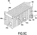
- the Figures 5A , 5B and 5C represent the third container 300 for preparing the emulsion, the last step of the process for preparing the emulsion by mixing the aqueous phase and the oily phase.
- the emulsion is produced in the third tank 310 by mixing the aqueous phase in the oily phase, the third tank 310 being equipped with stirrers 350.
- the oily phase is produced, during a previous step, at a temperature of 50 ° C. at 55 ° C to facilitate the temperature difference with the aqueous phase at 80-85 ° C and to facilitate the mixing of the two phases.
- the emulsion produced in the third tank 310 being of low viscosity, its consistency renders it unsuitable for its subsequent use for the preparation of the explosive.
- the emulsion is thus sent, after subtraction, into a shearing device 315 making it possible to increase the viscosity of the emulsion up to a set value.
- the emulsion is then stored temporarily in a buffer tank 320 before being subsequently conveyed to a silo or storage tank not shown.
- the temporary storage of the emulsion makes it easy to take samples for quality control at the laboratory 250. The operator can thus check the composition and the physical properties of the emulsion without reaching the end of a production cycle. . It can also have a visual control of the nature of the emulsion produced.
- the preparation of the emulsion in the third tank 310 is in two sub-steps.
- the third tank 310 is filled with aqueous phase and oily phase in proportions by weight of 85-95% of aqueous phase for 5-15% oily phase using flowmeters 311a and 311b.
- the third tank 310 is fed continuously in the aqueous phase and in the oily phase, while the pump 305 continuously withdraws an equivalent quantity of fluid emulsion and sends it into the body. 315.
- the respect of the aqueous phase / oily phase percentage is at all times guaranteed by the use of pumps equipped with mass flow meters.
- the mass flow rate of aqueous phase filling will be about 13 times greater than that of the oily phase.
- the two substeps follow one another so that the third tank 310 is never empty, the underflow flow rate of the emulsion from the tank 310 being constant.
- the tank 210 must contain the oily phase by exceeding because the mixing tank or third tank 310 is fed continuously from the first tank 110 and the second tank 210 until the first tank 110 has been exhausted.
- the opening 370a in the transverse wall before 300a of the third container adjacent to the first container 100 allows the passage of conduits the transport of the aqueous phase from the first tank 110 to the third tank 310 for preparing the the emulsion comprising a pipe 313 cooperating with an adjustable flowmeter 311b inside the third container.
- a connection element is advantageously provided at the end of the pipe portion 313 making it possible to make a quick connection with a portion of pipe extending inside the first container connected to the pumping unit 190 and the first tank.
- the other openings 370b, 370c and 370d of the third container are located on its rear longitudinal wall 300c not adjacent to the second container.
- the opening 370d located above the third emulsion preparation tank 310 makes it possible to communicate with an optional device for extracting vapors coming from the third emulsion preparation tank 310 via conduits. hydraulic.
- An opening 370c situated between the third emulsion preparation tank 310 and the small buffer tank 320 makes it possible to communicate with an optional emulsion 610 cooling module within an optional sixth container 600. More specifically, these hydraulic lines allow the connection of the cooling tower 615 and the plate heat exchanger 620 to the pipe 325 connecting the shear device to the buffer tank through a corresponding opening not shown.
- the opening 370b located behind the buffer tank 320 and allows the delivery of the emulsion to a silo or a storage tank 50 via a discharge pipe 335 cooperating with a valve336.
- a pipe 420 makes it possible to feed the first tank of the first container while a steam pipe 430 makes it possible to supply via a connection 284 at the orifice 270b of the longitudinal wall 200c free of the second container, a supply line 292 of the end 222 of the helical coil of the exchanger 220.
- boiler 410 provides the modular steam plant. In other embodiments, it could be considered that the boiler supplies the installation with hot fluid and in particular with hot water.
- ammonium nitrate is used for the preparation of the aqueous phase.
- Sodium or calcium nitrates could also be used.
- the fuel oil and the oil used for the preparation of the oil phase can be replaced by other vegetable and / or mineral oils.
Landscapes
- Chemical & Material Sciences (AREA)
- Engineering & Computer Science (AREA)
- Chemical Kinetics & Catalysis (AREA)
- Mechanical Engineering (AREA)
- Organic Chemistry (AREA)
- General Engineering & Computer Science (AREA)
- Thermal Sciences (AREA)
- Physics & Mathematics (AREA)
- Oil, Petroleum & Natural Gas (AREA)
- Inorganic Chemistry (AREA)
- Colloid Chemistry (AREA)
- Accessories For Mixers (AREA)
- Liquid Carbonaceous Fuels (AREA)
Description
La présente invention concerne une installation et un procédé de préparation d'un précurseur d'émulsion explosive constitués d'une émulsion inverse (d'eau dans l'huile) sur site.The present invention relates to an installation and a process for preparing an explosive emulsion precursor consisting of a reverse emulsion (water-in-oil) on site.
Afin de limiter les risques liés au transport, les précurseurs d'explosifs sont fabriqués sur site par émulsion d'une phase aqueuse concentrée, notamment sursaturée en nitrates constituant un comburant dans une phase huileuse contenant un agent tensioactif et constituant un mélange de combustibles.In order to limit the risks associated with transport, the explosive precursors are manufactured on site by emulsion of a concentrated aqueous phase, in particular supersaturated with nitrates constituting an oxidant in an oily phase containing a surfactant and constituting a mixture of fuels.
La phase aqueuse est préparée typiquement par dissolution de nitrates d'ammonium, et/ou de sodium et/ou de calcium dans de l'eau dans laquelle on ajoute des additifs favorisant la gazéification et des additifs permettant d'ajuster le pH de la phase aqueuse. En raison de la grande concentration de nitrates (en proportion pondérale d'environ 80-82% pour 18-20% d'eau) et afin de faciliter leur dissolution, l'eau est chauffée à une température d'au moins 65° C (degrés Celsius).The aqueous phase is typically prepared by dissolving ammonium nitrates, and / or sodium and / or calcium in water in which additives promoting gasification and additives to adjust the pH of the phase are added. aqueous. Due to the high concentration of nitrates (in weight proportion of about 80-82% for 18-20% water) and in order to facilitate their dissolution, the water is heated to a temperature of at least 65 ° C (degrees Celsius).
La phase huileuse se compose d'un mélange de différents corps gras végétaux ou minéraux et d'agents tensioactifs. Plus particulièrement, la phase huileuse obtenue par mélange d'huiles minérales neuves ou de récupération telle que des huiles paraffiniques et de fioul, de préférence dans une proportion pondérale de 50/50 à 80/20 avec une quantité d'agent tensioactif dans une proportion de 10 à 30% du total de la phase huileuseThe oily phase consists of a mixture of different vegetable or mineral fats and surfactants. More particularly, the oily phase obtained by mixing new mineral oils or recovery such as paraffinic oils and fuel oil, preferably in a proportion by weight of 50/50 to 80/20 with a quantity of surfactant in a proportion from 10 to 30% of the total oily phase
Pour favoriser le mélange et réduire l'écart de température entre la phase aqueuse et la phase huileuse avant leur mélange dans l'émulsion, la phase huileuse est chauffée à environ 40 - 90° C, de préférence 50-70°C.To promote mixing and reduce the temperature difference between the aqueous phase and the oily phase before mixing them in the emulsion, the oily phase is heated to about 40-90 ° C, preferably 50-70 ° C.
Pour le mélange et l'obtention de l'émulsion, on prépare un prémix de viscosité faible dans une cuve contenant des moyens d'agitation. De par sa faible viscosité, ce prémix a une stabilité insuffisante et une consistance impropre à son usage ultérieur pour la préparation de l'explosif. C'est pourquoi on augmente la viscosité du prémix à l'aide d'un dispositif de cisaillement pour obtenir une émulsion de viscosité plus élevée.For the mixing and obtaining of the emulsion, a premix of low viscosity is prepared in a tank containing agitation means. Because of its low viscosity, this premix has insufficient stability and consistency unsuitable for its subsequent use for the preparation of the explosive. This is why the viscosity of the premix is increased by means of a shearing device to obtain a higher viscosity emulsion.
En raison de la spécificité de l'émulsion constituant le précurseur d'explosif, celui-ci est fabriqué avantageusement sur site dans une installation modulaire transportable et montable sur site dans des conteneurs. Afin de faciliter le transport, les éléments permettant la mise en oeuvre du procédé de fabrication du précurseur sont transportés dans des conteneurs. L'agencement de ces éléments au sein des conteneurs est fait de telle sorte qu'il nécessite le moins d'opérations possibles relatives au montage de l'installation.Because of the specificity of the emulsion constituting the explosive precursor, it is advantageously manufactured on site in a modular installation transportable and mountable on site in containers. In order to facilitate the transport, the elements allowing the implementation of the precursor manufacturing process are transported in containers. The arrangement of these elements within the containers is made in such a way that it requires the least possible operations relating to the mounting of the installation.
Plus particulièrement, la présente invention concerne une installation modulaire permettant la mise en oeuvre d'un procédé de fabrication d'un précurseur d'émulsion explosive constitué d'une émulsion inverse d'eau dans l'huile comportant :
- a) une étape de préparation d'une phase aqueuse par dissolution de nitrates dans de l'eau et chauffage,
- b) une étape de préparation d'une phase huileuse par mélange de composants comprenant au moins un corps gras végétal et/ou minéral et un agent tensioactif et chauffage, et
- c) une étape de préparation de ladite émulsion par mélange de ladite phase aqueuse dans ladite phase huileuse. Ladite émulsion sera ultérieurement rendue explosive par ajouts et mélange de réactifs chimiques tel qu'une solution de nitrite de sodium et/ou des agents sensibilisants solides tels que des microsphères de verre dans des unités de fabrication sur site juste avant utilisation comme explosif destiné à être introduit dans les trous de mine.
- a) a step of preparing an aqueous phase by dissolving nitrates in water and heating,
- b) a step of preparing an oily phase by mixing components comprising at least one vegetable and / or mineral fatty substance and a surfactant and heating, and
- c) a step of preparing said emulsion by mixing said aqueous phase in said oily phase. Said emulsion will subsequently be made explosive by additions and mixing of chemical reagents such as a solution of sodium nitrite and / or agents solid sensitizers such as glass microspheres in manufacturing units on site just prior to use as an explosive for introduction into the boreholes.
On connait dans
On connaît de l'art antérieur une installation modulaire composée essentiellement de deux grands conteneurs d'environ 12,2 m (40 pieds) juxtaposés et communiquant sur l'une de leurs faces longitudinales. L'un des conteneurs comprend des cuves de dissolution pour la préparation de la phase aqueuse ainsi qu'une chaudière séparée par une cloison. L'autre conteneur comprend les cuves de préparation de la phase huileuse et de l'émulsion inverse ainsi qu'une installation électrique séparée. Ainsi, les trois étapes de préparation de l'émulsion se trouvent dans un conteneur commun. Le fait que les trois étapes de préparation de l'émulsion se trouvent dans un même conteneur présente des risques pour la sécurité du site et/ou des opérateurs en cas d'incident et/ou d'avarie.A modular installation is known from the prior art, consisting essentially of two large containers approximately 12.2 m (40 feet) juxtaposed and communicating on one of their longitudinal faces. One of the containers comprises dissolving tanks for the preparation of the aqueous phase and a boiler separated by a partition. The other container comprises the preparation tanks for the oily phase and the inverse emulsion and a separate electrical installation. Thus, the three stages of preparation of the emulsion are in a common container. The fact that the three stages of preparation of the emulsion are in the same container poses risks for the safety of the site and / or the operators in the event of an incident and / or damage.
De plus, le transport de conteneurs d'une telle grande taille n'est pas aisé. Or, il est souhaitable de pouvoir transporter les conteneurs déjà installés car si l'installation est assemblée sur site, elle nécessite le déplacement de personnel qualifié, ce qui engendre des coûts supplémentaires, notamment si l'on souhaite ajouter des éléments optionnels par la suite.In addition, the transport of such large containers is not easy. However, it is desirable to be able to transport the containers already installed because if the installation is assembled on site, it requires the movement of qualified personnel, which generates additional costs, especially if one wishes to add optional elements thereafter .
On entend ici par « conteneur » (encore dénommés « container ») des caissons en tôle d'acier utilisés pour le transport de marchandises selon des caractéristiques normalisées, et notamment selon les normes ISO 668 et ISO 1496.Here "container" (also referred to as "container") is understood to mean steel sheet boxes used for the transport of goods according to standardized characteristics, and in particular according to ISO 668 and ISO 1496 standards.
La présente invention vise notamment à résoudre les inconvénients de l'art antérieur précités.The present invention aims in particular to solve the disadvantages of the aforementioned prior art.
Plus particulièrement, le but de la présente invention est de fournir une installation modulaire améliorée, qui permet d'optimiser les conditions de :
- encombrement et d'emprise au sol de l'installation sur son lieu final d'implantation en vue d'un rendement de production maximal, et
- transport de l'installation, et
- sécurité à la fois du transport et de l'exploitation par le personnel chargé de l'exploitation de l'installation, y compris optimisation des conditions de circulation et de travail du personnel dans l'installation.
- congestion and footprint of the installation at its final location for maximum production efficiency, and
- transport of the installation, and
- safety of both the transport and the operation by the personnel responsible for the operation of the installation, including the optimization of the traffic and working conditions of the personnel in the installation.
Plus particulièrement encore, l'installation doit être :
- facilement transportable sans contrainte particulière, et
- facilement assemblable sur site sans nécessiter un trop grand nombre d'heures de travail et de compétences spécifiques, et
- totalement autonome en énergie et autres ressources de matières premières nécessaires et/ou facilement raccordable à des facilités sur le lieu d'exploitation, et
- capable de produire au moins 25 tonnes/jour d'émulsion, soit environ 6000 tonnes/an, et
- évolutive avec possibilité d'ajout de fonctionnalités dans le temps.
- démontable pour être transporté à nouveau et installé sur un autre site, et ce éventuellement à plusieurs reprises.
- easily transportable without any particular constraint, and
- Easily assembled on site without requiring too many hours of work and specific skills, and
- totally autonomous in energy and other resources of necessary raw materials and / or easily connected to facilities at the place of exploitation, and
- capable of producing at least 25 tonnes / day of emulsion, or about 6000 tonnes / year, and
- scalable with possibility of adding features over time.
- removable to be transported again and installed on another site, and this possibly several times.
Plus précisément, l'invention fournit une installation modulaire tel que défini ci-dessus comportant les conteneurs suivants agencés comme suit :
- un premier conteneur dédié à la préparation de la phase aqueuse, ledit premier conteneur comprenant une première cuve de dissolution pourvue de premiers moyens de chauffage et de premiers moyens d'agitation de la phase aqueuse contenus dans la première cuve, et ledit premier conteneur contenant des premiers moyens de circulation par pompage d'au moins ladite phase aqueuse et l'eau d'alimentation de ladite première cuve depuis une première cuve externe, et
- un deuxième conteneur contenant une deuxième cuve contenant des deuxièmes moyens de chauffage et deuxièmes moyens d'agitation dédiés à la préparation de la phase huileuse, et un troisième conteneur contenant une dite troisième cuve contenant des troisièmes moyens d'agitation dédiés à la préparation de l'émulsion, et
- au moins l'un desdits deuxième et/ou troisième conteneurs contenant des deuxièmes moyens de circulation par pompage de ladite phase huileuse depuis la deuxième cuve vers la troisième cuve et circulation des composants de la phase huileuse depuis des cuves de stockage externes desdits composants vers ladite deuxième cuve, et des troisièmes moyens de circulation par pompage d'évacuation de ladite émulsion depuis ladite troisième cuve vers une cuve de stockage de l'émulsion, et
- au moins un quatrième et/ou cinquième conteneur comportant des moyens de fourniture de fluide caloporteur permettant d'alimenter en fluide caloporteur lesdits moyens de chauffage et des moyens de fourniture d'énergie électrique permettant d'alimenter en électricité au moins lesdits moyens de circulation de fluide par pompage et lesdits moyens d'agitation, de préférence un quatrième conteneur contenant des moyens de fourniture de fluide caloporteur et un cinquième conteneur contenant des moyens de fourniture d'énergie électrique ,
- lesdits premier, deuxième et/ou troisième conteneurs étant juxtaposés au moins sur une partie d'une de leurs parois latérales, de façon à ce qu'au moins une partie d'une paroi latérale dudit premier conteneur est juxtaposée à au moins une partie d'une paroi latérale dudit troisième conteneur, et au moins une partie d'une paroi latérale du deuxième conteneur est juxtaposée à au moins une partie d'une autre paroi latérale du troisième conteneur, de sorte que ledit troisième conteneur est intercalé entre ledit premier conteneur et ledit deuxième conteneur, et
- lesdits premier, deuxième et/ou troisième conteneurs comprenant, au niveau de leur parois, des ouvertures par lesquelles passent et/ou sont connectées des conduites de transfert de fluide entre lesdits conteneurs et/ou des câbles électriques,
- lesdites ouvertures étant obturables, notamment pouvant être obturées lors du transport des conteneurs.
- a first container dedicated to the preparation of the aqueous phase, said first container comprising a first dissolution tank provided with first heating means and first means for stirring the aqueous phase contained in the first tank, and said first container containing first circulation means by pumping at least said aqueous phase and the supply water of said first tank from a first external vessel, and
- a second container containing a second tank containing second heating means and second stirring means dedicated to the preparation of the oily phase, and a third container containing a said third tank containing third stirring means dedicated to the preparation of the second emulsion, and
- at least one of said second and / or third containers containing second circulation means by pumping said oily phase from the second tank to the third tank and circulation of the oily phase components from external storage tanks of said components to said second tank, and third pump means for evacuation of said emulsion from said third tank to a storage tank of the emulsion, and
- at least one fourth and / or fifth container having means for supplying heat transfer fluid for supplying heat transfer fluid with said heating means and means for supplying electrical energy making it possible to supply electricity to at least said means for circulating heat. pumped fluid and said stirring means, preferably a fourth container containing heat transfer fluid supply means and a fifth container containing electrical energy supply means,
- said first, second and / or third containers being juxtaposed at least on a portion of one of their side walls, so that at least a portion of a side wall of said first container is juxtaposed with at least a portion of a side wall of said third container, and at least a portion of a side wall of the second container is juxtaposed with at least a portion of another side wall of the third container, such that said third container is interposed between said first container and said second container, and
- said first, second and / or third containers comprising, at their walls, openings through which fluid transfer lines between said containers and / or electrical cables pass and / or are connected,
- said openings being closable, in particular being closable during the transport of the containers.
On comprend qu'ainsi lesdits premiers conteneurs et deuxième conteneurs ne sont pas juxtaposés l'un à l'autre et sont donc séparés physiquement par le troisième conteneur, ce qui permet de séparer physiquement le comburant (phase aqueuse) et le combustible (phase huileuse) et d'éviter tout mélange accidentel inapproprié et dangereux.It is thus understood that said first containers and second containers are not juxtaposed to one another and are therefore physically separated by the third container, which makes it possible to physically separate the oxidant (aqueous phase) and the fuel (oily phase ) and avoid any inappropriate and dangerous accidental mixing.
Du fait que le premier conteneur est exclusivement et entièrement dédié à la préparation de ladite phase aqueuse, il est possible de mettre en oeuvre un premier conteneur de petite taille, notamment un conteneur de taille standard d'environ 6,1 m de longueur (20 pieds). De même, du fait que l'on met en oeuvre une pluralité de conteneurs juxtaposés, dédiés chacun à un nombre limité d'étapes et/ou de matériel, au total, l'installation rempli plus facilement les buts de l'invention que les installations de la technique antérieure.Since the first container is exclusively and entirely dedicated to the preparation of said aqueous phase, it is possible to implement a first small container, including a standard size container of about 6.1 m in length (20 feet). Similarly, because a plurality of juxtaposed containers, each dedicated to a limited number of steps and / or equipment, is used in total, the installation more easily fulfills the aims of the invention than the installations of the prior art.
D'autre part, le fait que les principaux conteneurs de préparation de phase aqueuse/préparation de phase huileuse et mélange de l'émulsion sont juxtaposés sur au moins une de leurs parois latérales, permet d'optimiser l'encombrement et emprise au sol d'une part, et surtout facilite d'exploitation de l'installation et minimise les risques d'exploitation pour le personnel d'exploitation.On the other hand, the fact that the main containers of aqueous phase preparation / oil phase preparation and mixing of the emulsion are juxtaposed on at least one of their side walls, makes it possible to optimize the footprint and footprint of the product. on the one hand, and above all, facilitates the operation of the installation and minimizes the operating risks for the operating staff.
Enfin, du fait que les conteneurs sont pourvus d'ouvertures équipées d'éléments de connexion/déconnexion rapide des conduites de transfert de fluide, comprenant le fluide de matière première de phase aqueuse ou phase huileuse ou émulsion, mais aussi le fluide calorifique éventuel pour les moyens de chauffage, et des câbles électriques, le montage/démontage de l'installation ainsi que son transport sont facilités.Finally, because the containers are provided with openings equipped with quick connection / disconnection elements of the fluid transfer lines, comprising the aqueous phase raw material fluid or oil phase or emulsion, but also the possible heat transfer fluid for the heating means and electrical cables, the assembly / disassembly of the installation and its transport are facilitated.
L'installation modulaire selon l'invention présente l'avantage d'être ainsi facilement transportable puisque l'installation, lorsqu'elle a été démontée, se présente sous la forme de conteneurs standards de relativement plus petite taille.The modular installation according to the invention has the advantage of being easily transportable since the installation, when disassembled, is in the form of standard containers of relatively smaller size.
En outre, l'installation est ainsi plus facilement démontable et remontable par un opérateur qualifié. L'installation ayant été préalablement montée et testée sur le lieu de fabrication de l'installation, l'opérateur ne doit rétablir, lors du montage de l'installation sur site, que les connections entre les différents conteneurs.In addition, the installation is thus more easily removable and reassembly by a qualified operator. Since the installation was previously assembled and tested at the place of manufacture of the installation, the operator must only restore the connections between the different containers when assembling the installation on site.
Au surplus, la modularité de l'installation se trouve renforcée puisqu'il est possible d'ajouter facilement un conteneur contenant un équipement optionnel, comme une tour de refroidissement et un échangeur à plaques ; l'équipement optionnel pouvant être raccordé à l'installation sur site par le biais des ouvertures pratiquées préalablement dans les différents conteneurs.In addition, the modularity of the installation is enhanced because it is possible to easily add a container containing a optional equipment, such as a cooling tower and a plate heat exchanger; the optional equipment that can be connected to the on-site installation through the openings previously made in the different containers.
Enfin et surtout, l'installation permet de limiter les risques pour la sécurité du personnel en cas d'incendie ou d'avarie par une séparation physique de la phase aqueuse (constituant le comburant) et de la phase huileuse (constituant le combustible) mais aussi une séparation du mélange comburant/combustible et de la chaudière.Last but not least, the installation makes it possible to limit the risks for the safety of personnel in case of fire or damage by a physical separation of the aqueous phase (constituting the oxidant) and the oily phase (constituting the fuel) but also a separation of the oxidant / fuel mixture and the boiler.
Plus particulièrement, lesdites conduites de transfert de fluide sont :
- une conduite de transfert de ladite phase aqueuse entre la première cuve et la troisième cuve,
- une conduite de transfert de fluide caloporteur entre lesdits moyens de fourniture de fluide caloporteur et lesdits moyens de chauffage de ladite première cuve, et
- une conduite de transfert de phase huileuse entre ladite deuxième cuve et ladite troisième cuve,
- une conduite de transfert de fluide caloporteur entre lesdits moyens de fourniture de fluide caloporteur et lesdits moyens de chauffage de ladite deuxième cuve, et
- une conduite d'évacuation de ladite émulsion entre ladite troisième cuve et une cuve de stockage de l'émulsion, et
- des conduites d'alimentation de ladite deuxième cuve en huile et agents tensioactifs depuis des cuves de stockage externes.
- a pipe for transferring said aqueous phase between the first tank and the third tank,
- a heat transfer fluid transfer line between said heat transfer fluid supply means and said heating means of said first tank, and
- an oily phase transfer line between said second tank and said third tank,
- a heat transfer fluid transfer line between said heat transfer fluid supply means and said heating means of said second tank, and
- a conduit for discharging said emulsion between said third vessel and a storage tank of the emulsion, and
- supply lines for said second oil tank and surfactants from external storage tanks.
De même, lesdits groupes de pompages comprennent plus particulièrement :
- une pompe d'alimentation en eau de ladite première cuve depuis une dite citerne externe,
- une pompe de circulation de la phase aqueuse depuis ladite première cuve vers ladite troisième cuve,
- des pompes d'alimentation en huile et tensioactif depuis des cuves de stockage externes vers ladite deuxième cuve, et
- une pompe de circulation de ladite phase huileuse depuis ladite deuxième cuve vers ladite troisième cuve, et
- une pompe d'évacuation de ladite émulsion depuis ladite troisième cuve vers une cuve de stockage de l'émulsion à l'intérieur et/ou à l'extérieur du troisième conteneur.
- a pump for supplying water to said first tank from an said external tank,
- a pump for circulating the aqueous phase from said first tank to said third tank,
- oil and surfactant feed pumps from external storage tanks to said second tank, and
- a pump for circulating said oily phase from said second tank to said third tank, and
- a pump for discharging said emulsion from said third tank to a storage tank for the emulsion inside and / or outside the third container.
Plus particulièrement encore, lesdites conduites de transfert de fluide sont de préférence constituées de portions de conduites équipées d'éléments de connexion connectables et dé-connectables au niveau desdites ouvertures.More particularly, said fluid transfer lines are preferably constituted by pipe portions equipped with connectable and de-connectable connection elements at said openings.
Plus particulièrement encore, lesdits câbles électriques sont constitués de portions de câbles équipées d'élément de connexion connectables et dé-connectables à des prises complémentaires au niveau desdites parois de conteneurs et/ou au niveau de dites ouvertures.More particularly, said electric cables consist of cable portions equipped with connectable connecting element and de-connectable to complementary sockets at said container walls and / or at said openings.
Plus particulièrement, ledit quatrième conteneur contient des moyens de fourniture du fluide chaud comprenant une chaudière de production de vapeur d'eau, lesdits moyens de chauffage étant des échangeurs thermiques dans lesquels circule ladite vapeur d'eau.More particularly, said fourth container contains hot fluid supply means comprising a boiler for producing water vapor, said heating means being heat exchangers in which circulates said steam.
De façon avantageuse, lesdites ouvertures au niveau des parois des conteneurs juxtaposés comportent en outre des moyens de liaison entre les conteneurs.Advantageously, said openings at the walls of the juxtaposed containers further comprise connecting means between the containers.
Dans un mode particulier de réalisation, l'installation comprend desdits premier, deuxième et troisième conteneurs parallélépipédiques de tailles standards, notamment selon les normes ISO 668 et ISO 1496, de préférence plus petits que le quatrième conteneur, de préférence d'environ 6,1 m (20 pieds) de longueur, juxtaposés comme suit :
- au moins une partie avant d'une paroi latérale longitudinale du premier conteneur à proximité d'une paroi latérale transversale avant équipée de porte(s) du premier conteneur est juxtaposée avec une partie au moins d'une paroi latérale, de préférence une paroi latérale transversale avant, dudit troisième conteneur, ladite partie avant de la paroi latérale longitudinale du premier conteneur étant pourvue d'une première petite ouverture débouchant sur la partie du premier conteneur comprenant des premiers moyens de circulation par pompage, ladite première petite ouverture étant juxtaposée en vis-à-vis d'une deuxième petite ouverture dans ladite paroi latérale du troisième conteneur, lesdites première et deuxième petites ouvertures permettant le passage et/ou la connexion de conduites de transfert de la phase aqueuses depuis ladite première cuve vers ladite troisième cuve, et
- une première paroi latérale longitudinale du deuxième conteneur pourvue d'une première grande ouverture étant juxtaposée à une première paroi latérale longitudinale du troisième conteneur pourvue d'une deuxième grande ouverture en vis-à-vis de ladite première grande ouverture, lesdites première et deuxième grandes ouvertures permettant le passage du personnel et le passage de dites conduites de transfert de fluide entre lesdits deuxième et troisième conteneurs, une paroi latérale transversale avant du deuxième conteneur comprenant d'une porte en alignement avec ladite paroi transversale avant du troisième conteneur, et
- une deuxième paroi latérale longitudinale du deuxième conteneur comprenant d'au moins une troisième petite ouverture permettant le passage et/ou la connexion de conduites de transfert des composants de la phase huileuse depuis des cuves externes de stockage des composants de la phase huileuse vers ladite deuxième cuve et passage et/ou connexion de la conduite de transfert de fluide caloporteur depuis lesdits moyens de fourniture de fluide caloporteur vers lesdits deuxièmes moyens de chauffage de ladite deuxième cuve, et
- une deuxième paroi latérale longitudinale du troisième conteneur étant pourvue d'au moins une ouverture permettant le passage et/ou la connexion de conduites d'évacuation de ladite émulsion depuis ladite troisième cuve vers une cuve de stockage de l'émulsion.
- at least one front portion of a longitudinal side wall of the first container near a front transverse side wall equipped with door (s) of the first container is juxtaposed with at least a portion of a side wall, preferably a side wall transverse front of said third container, said front portion of the longitudinal side wall of the first container being provided with a first small opening opening on the portion of the first container comprising first pumped circulation means, said first small opening being juxtaposed with a screw a second small opening in said side wall of the third container, said first and second small openings allowing passage and / or connection of aqueous phase transfer lines from said first tank to said third tank, and
- a first longitudinal side wall of the second container provided with a first large opening being juxtaposed with a first longitudinal side wall of the third container provided with a second large opening opposite said first large opening, said first and second large openings for the passage of personnel and the passage of said fluid transfer lines between said second and third containers, a front transverse side wall of the second container comprising a door in alignment with said front transverse wall of the third container, and
- a second longitudinal side wall of the second container comprising at least a third small opening allowing the passage and / or the connection of transfer lines of the components of the oily phase from external storage tanks of the components of the oily phase to the second tank and passage and / or connection of the heat transfer fluid transfer line from said heat transfer fluid supply means to said second heating means of said second tank, and
- a second longitudinal side wall of the third container being provided with at least one opening allowing the passage and / or the connection of drain lines of said emulsion from said third tank to a storage tank of the emulsion.
Cette juxtaposition des conteneurs et le passage d'un opérateur étant rendu possible par la présence d'une grande ouverture permet une meilleure gestion de l'espace dans les conteneurs et une amélioration de l'ergonomie, et la longueur des conduites hydrauliques acheminant les phases aqueuse et huileuse vers la cuve de préparation de l'émulsion est optimisée.This juxtaposition of the containers and the passage of an operator being made possible by the presence of a large opening allows a better management of the space in the containers and an improvement of the ergonomics, and the length of the hydraulic lines carrying the phases aqueous and oily to the preparation tank of the emulsion is optimized.
Plus particulièrement, ladite installation comprend :
- ledit premier conteneur comprend une portion de conduite de transfert de fluide depuis ladite première cuve vers ladite troisième cuve, ainsi que une portion de conduite de transfert de fluide caloporteur entre lesdits moyens de fournitures de fluide caloporteur et lesdits premiers moyens de chauffage à l'intérieur de ladite première cuve, et une portion de conduite d'alimentation en eau de ladite première cuve, et
- ledit deuxième conteneur contient une portion de conduite de transfert de phase huileuse entre ladite deuxième cuve et ladite troisième cuve, ainsi que une portion de conduite de transfert de fluide caloporteur entre lesdits moyens de fournitures de fluide caloporteur et lesdits deuxièmes moyens de chauffage à l'intérieur de ladite deuxième cuve, et des portions de conduites d'alimentation en huile et respectivement en agents tensioactifs dans de ladite deuxième cuve, et
- ledit troisième conteneur contient une portion de conduite de transfert de phase aqueuse depuis ladite première cuve vers ladite troisième cuve et une portion de conduite de transfert de phase huileuse depuis ladite deuxième cuve vers ladite troisième cuve, et une portion de conduite d'évacuation de ladite émulsion depuis ladite troisième cuve vers une cuve extérieure de stockage et/ou une cuve tampon de stockage de ladite émulsion.
- said first container comprises a fluid transfer line portion from said first tank to said third tank, as well as a heat transfer fluid transfer line portion between said heat transfer fluid supply means and said first heating means therein said first tank, and a water supply line portion of said first tank, and
- said second container contains an oily phase transfer line portion between said second tank and said third tank, as well as a heat transfer fluid transfer line portion between said heat transfer fluid supply means and said second heating means at the same. inside said second tank, and portions of oil supply lines and surfactants respectively in said second tank, and
- said third container contains an aqueous phase transfer line portion from said first tank to said third tank and an oil phase transfer line portion from said second tank to said third tank, and an exhaust pipe portion of said emulsion since said third tank to an outer storage tank and / or a storage buffer tank of said emulsion.
Selon un autre aspect de la présente invention, le premier conteneur comporte une première cuve parallélépipédique avec au moins 5 parois disposées parallèlement et sensiblement de même dimensions que respectivement au moins 5 parois dudit premier conteneur, lesdits premiers moyens de chauffage de ladite première cuve comprenant un premier échangeur thermique tubulaire, ledit premier échangeur thermique tubulaire étant constitué d'un réseau de conduites de transfert de fluide caloporteur disposées longitudinalement et transversalement, en continu, à différents niveaux en hauteur, aptes à chauffer le liquide contenu dans ladite première cuve parallélépipédique en distribuant la chaleur du fluide caloporteur circulant dans ledit réseau de conduites dans tout le volume de ladite première cuve avec, de préférence, un plus grand nombre de conduites dans la partie inférieure de la première cuve, et ledit premier conteneur contenant en outre desdits premiers moyens de circulation par pompage de fluide situés entre une sixième paroi latérale transversale de ladite première cuve et une paroi latérale transversale avant dudit premier conteneur.According to another aspect of the present invention, the first container comprises a first parallelepipedic tank with at least 5 walls arranged in parallel and of substantially the same dimensions as respectively at least 5 walls of said first container, said first heating means of said first tank comprising a first tubular heat exchanger, said first tubular heat exchanger consisting of a network of heat transfer fluid transfer lines arranged longitudinally and transversely, continuously, at different levels in height, able to heat the liquid contained in said first parallelepipedic tank by distributing the heat of the heat transfer fluid circulating in said pipe network throughout the volume of said first tank with, preferably, a greater number of pipes in the lower part of the first tank, and said first container also containing said first means fluid pump circulation system located between a sixth transverse sidewall of said first vessel and a front transverse sidewall of said first vessel.
Cette caractéristique permet de répartir de façon appropriée la chaleur.This characteristic makes it possible to distribute the heat appropriately.
L'utilisation d'une cuve parallélépipédique permet une optimisation du volume du premier conteneur au regard de la quantité de phase aqueuse pouvant être produite dans le premier conteneur. Les proportions massiques utilisées pour la préparation de l'émulsion inverse étant d'environ 90% de phase aqueuse pour environ 10% de phase huileuse, la capacité de production de l'installation modulaire dépend directement de la quantité de phase aqueuse produite. L'utilisation d'une cuve parallélépipédique permet donc une optimisation de l'utilisation de l'espace du premier conteneur.The use of a parallelepipedic tank makes it possible to optimize the volume of the first container with regard to the quantity of aqueous phase that can be produced in the first container. Since the mass proportions used for the preparation of the inverse emulsion are approximately 90% aqueous phase for approximately 10% oily phase, the production capacity of the modular installation depends directly on the quantity of aqueous phase produced. The use of a parallelepipedic tank therefore makes it possible to optimize the use of the space of the first container.
Le fait que le premier conteneur comporte également des moyens de pompage supportés par un châssis fixe à l'intérieur dudit conteneur et situés entre la première cuve de préparation de la phase aqueuse et l'une des parois du conteneur, présente l'avantage de faciliter l'accès de l'opérateur aux moyens de pompage tout en lui limitant l'accès au dangers représentés par la nature des opérations réalisées dans cuve de préparation de la phase aqueuse.The fact that the first container also comprises pumping means supported by a fixed frame inside said container and located between the first preparation tank of the aqueous phase and one of the walls of the container, has the advantage of facilitating the access of the operator to the pumping means while limiting access to the hazards represented by the nature of the operations performed in the preparation tank of the aqueous phase.
Selon un autre aspect de l'invention, ledit premier échangeur thermique de la première cuve parallélépipédique comporte un réseau de conduites longitudinales cylindriques disposées en continu à différents niveaux en hauteur, des conduites longitudinales disposées sensiblement à un même niveau en hauteur étant reliées entre elles à leurs extrémités d'un même côté par des éléments de conduite formant des connecteurs horizontaux transversaux, et une extrémité d'au moins une conduite longitudinale disposée à un niveau donné étant reliée à l'extrémité d'une conduite longitudinale disposée au niveau du dessous ou du dessus par au moins un élément de conduite coudé vertical, les conduites des niveaux supérieurs étant disposées en pentes légèrement inclinées descendantes de préférence d'un angle inférieur à 10° par rapport à l'horizontal dans le sens de circulation du fluide caloporteur depuis un orifice d'alimentation supérieur au niveau d'un connecteur transversal supérieur vers un orifice d'évacuation inférieure au niveau d'un premier connecteur transversal inférieur.According to another aspect of the invention, said first heat exchanger of the first parallelepipedic tank comprises a network of longitudinal cylindrical conduits arranged continuously at different levels in height, longitudinal lines arranged substantially at the same level in height being connected to each other at their ends on the same side by pipe elements forming transverse horizontal connectors, and an end of at least one longitudinal pipe arranged at a given level being connected to the end of a longitudinal pipe arranged at the bottom or from above by at least one vertical bend pipe element, the pipes of the upper levels being arranged in slightly inclined descending slopes, preferably at an angle of less than 10 ° to the horizontal in the direction of circulation of the coolant since a upper supply port at a c upper transverse nozzle to a lower discharge port at a first lower transverse connector.
Cette structure particulière de l'échangeur thermique tubulaire est adaptée à la forme parallélépipédique de la cuve de dissolution des nitrates et permet une optimisation de la distribution de chaleur dans la cuve.This particular structure of the tubular heat exchanger is adapted to the parallelepipedal shape of the nitrate dissolution tank and allows optimization of the heat distribution in the tank.
Plus particulièrement, le premier échangeur thermique au sein de la première cuve comporte :
- un étage inférieur de dites conduites longitudinales couvrant le plancher de ladite première cuve parallélépipédique, lesdites conduites de l'étage inférieur étant régulièrement espacées dans la direction transversale de la première cuve et s'étendant dans la direction longitudinale sensiblement horizontalement depuis au moins un deuxième connecteur transversal inférieur vers ledit premier connecteur transversal inférieur, et
- au moins un étage supérieur de dites conduites longitudinales en plus petit nombre que les conduites de l'étage inférieur, les conduites dudit étage supérieur étant regroupées de part et d'autre d'un espace central de dimension dans la direction transversale de la cuve plus grande que l'espace entre deux dites conduites adjacentes positionnées d'un même côté dudit espace central, ledit espace central contenant une partie desdits premiers moyens d'agitation de la phase aqueuse de préférence positionnés en partie à une hauteur entre ledit étage supérieur et dit étage inférieur, de préférence encore une autre partie desdits premiers moyens d'agitation étant positionnés au-dessus dudit étage supérieur.
- a lower floor of said longitudinal ducts covering the floor of said first parallelepipedic tank, said ducts of the lower floor being evenly spaced in the direction transverse to the first vessel and extending in the longitudinal direction substantially horizontally from at least one second lower transverse connector to said first lower transverse connector, and
- at least one upper stage of said longitudinal ducts in smaller number than the pipes of the lower stage, the pipes of said upper stage being grouped on either side of a central space of dimension in the transverse direction of the tank more large than the space between two said adjacent pipes positioned on the same side of said central space, said central space containing a portion of said first aqueous phase stirring means preferably positioned partly at a height between said upper stage and said lower stage, more preferably another part of said first stirring means being positioned above said upper stage.
Le plus grand nombre de conduites à l'étage inférieur de l'échangeur est destiné à chauffer l'eau initialement introduite dans la cuve de façon optimale à une température initiale supérieure à 65-70 degrés Celsius, car c'est à ce stade, que le maximum de calories est requis. L'étage supérieur permet de chauffer le reste de la première cuve lorsque le volume de phase aqueuse (18-20%) contenue dans la première cuve notamment environ 4 T augmente lors de la dissolution des granulés de nitrate (80-82%), notamment environ 20 T pour former environ 24 T de phase aqueuse. La présence d'agitateurs entre ces deux éléments de chauffage permet de mieux répartir la chaleur au sein de la première cuve et de favoriser la dissolution homogène des granulés de nitrate dans la cuve.The greatest number of pipes at the lower stage of the exchanger is intended to heat the water initially introduced into the tank optimally at an initial temperature greater than 65-70 degrees Celsius, because it is at this stage, that the maximum of calories is required. The upper stage makes it possible to heat the remainder of the first tank when the volume of aqueous phase (18-20%) contained in the first tank, in particular approximately 4 T, increases during the dissolution of the nitrate granules (80-82%), in particular about 20 T to form about 24 T of aqueous phase. The presence of stirrers between these two heating elements makes it possible to better distribute the heat within the first tank and to promote the homogeneous dissolution of the nitrate granules in the tank.
De façon avantageuse, les conduites parallèles appartenant substantiellement à un même étage de l'échangeur sont inclinées vers le bas de la cuve afin de favoriser l'écoulement de vapeur. Le réseau de conduites cylindriques en continu dont certaines sont orientées vers le bas de la cuve parallélépipédique permet une meilleure circulation de la vapeur et le recueillement des condensats à la sortie de la cuve.Advantageously, the parallel pipes substantially belonging to the same stage of the exchanger are inclined downwardly of the vessel to promote the flow of steam. The network of continuous cylindrical pipes some of which are oriented towards the bottom of the parallelepipedic tank allows a better circulation of the steam and the collection of condensate at the outlet of the tank.
De façon avantageuse, le toit du premier conteneur et le plafond de ladite première cuve sont pourvues de premières ouvertures en vis-à-vis l'une de l'autre entourées de premières parois verticales de rehausses de préférence amovibles s'étendant depuis le plafond de la première cuve jusqu'au-dessus du toit du premier conteneur et lesdites premières parois de rehausse supportant ou étant aptes à supporter des éléments permettant l'acheminement du nitrate dans la première cuve à travers lesdites premières ouvertures, le nitrate étant de préférence acheminé dans la première cuve à l'aide d'une vis de décharge, le nitrate étant réparti à l'intérieur de la première cuve en direction des premiers moyens d'agitation à l'aide d'au moins un déflecteur disposé dessous la première ouverture du plafond de la première cuve, lesdites premières ouvertures du plafond de la première cuve et du toit du premier conteneur étant de préférence obturables, pouvant être obturées lors du transport desdits premier conteneur et dite première cuve.Advantageously, the roof of the first container and the ceiling of said first tank are provided with first openings vis-à-vis one of the other surrounded by first vertical walls of preferably removable extensions extending from the ceiling from the first tank to above the roof of the first container and said first riser walls supporting or being able to support elements permitting the delivery of the nitrate into the first tank through said first openings, the nitrate being preferably conveyed in the first tank using a discharge screw, the nitrate being distributed inside the first tank towards the first stirring means using at least one deflector disposed below the first opening the ceiling of the first tank, said first openings of the ceiling of the first tank and the roof of the first container being preferably closable, being e closed during the transport of said first container and said first tank.
Ainsi, l'espace utilisé par la première cuve parallélépipédique dans le premier conteneur est maximisé, les éléments en interaction avec la première cuve ne sont pas enfermés dans le premier conteneur et peuvent en dépasser. Ils sont de plus facilement démontables.Thus, the space used by the first parallelepipedic tank in the first container is maximized, the elements interacting with the first tank are not enclosed in the first container and may exceed. They are more easily removable.
Le démontage des moyens d'acheminement de nitrates lors du transport est facilité par la présence d'une rehausse démontable en regard d'une ouverture se trouvant sur le toit du conteneur.Disassembly of the nitrate conveying means during transport is facilitated by the presence of a removable riser opposite an opening on the roof of the container.
Avantageusement, le toit du premier conteneur et le plafond de la première cuve comportent des deuxièmes ouvertures en vis-à-vis l'une de l'autre, entourées de deuxièmes parois verticales de rehausse de préférence amovibles, lesdites deuxièmes parois de rehausse s'étendant depuis le plafond de la première cuve jusqu'au-dessus du toit du premier conteneur, lesdites deuxièmes parois de rehausse supportant des premiers moyens d'agitation comprenant au moins une tige verticale s'étendant à l'intérieur de la première cuve sur laquelle sont montées des pâles rotatives d'agitation aptes à être actionnées en rotation au tour d'un axe vertical à l'aide d'un moteur, ledit moteur étant de préférence fixé de façon non permanente sur le toit du premier conteneur, lesdites deuxièmes ouvertures étant de préférence obturables, pouvant ainsi être obturées lors du transport.Advantageously, the roof of the first container and the ceiling of the first tank comprise second openings vis-à-vis one another, surrounded by second vertical walls preferably removable removable, said second walls of raises s' extending from the ceiling of the first tank to above the roof of the first container, said second riser walls supporting first stirring means comprising at least one vertical rod extending inside the first vessel on which are mounted rotary stirring blades able to be actuated in rotation around a vertical axis by means of a motor, said motor preferably being fixed by non-permanently on the roof of the first container, said second openings being preferably closable, thus being closable during transport.
Le démontage du moteur de l'agitateur lors du transport est facilité par la présence d'une rehausse démontable en regard d'une ouverture se trouvant sur le toit du conteneur.Disassembly of the agitator motor during transport is facilitated by the presence of a detachable riser opposite an opening on the roof of the container.
Dans un mode particulier de réalisation, le deuxième conteneur dédié à la préparation de la phase huileuse comporte une seule deuxième cuve supportée par des pesons comprenant à l'intérieur de la deuxième cuve des deuxièmes moyens de chauffage comprenant un deuxième échangeur thermique de forme hélicoïdale.In a particular embodiment, the second container dedicated to the preparation of the oily phase comprises a single second tank supported by load cells comprising inside the second tank of the second heating means comprising a second heat exchanger of helical shape.
L'utilisation d'une cuve à pesons permet, de façon avantageuse, de connaître précisément la quantité de phase huileuse restante dans la deuxième cuve après préparation de l'émulsion afin de calculer la quantité de phase huileuse à produire pour le prochain cycle de production. La deuxième cuve à pesons permet également de contrôler la quantité de phase huileuse produite lors de chaque nouveau cycle de production. Cette solution est particulièrement originale et avantageuse par rapport à l'art antérieur dans lequel on utilise deux cuves communiquant entre elles et équipées de niveaux en haut d'une première cuve, une deuxième cuve contenant le reliquat, l'utilisation de niveaux étant moins précise comme explicité ci-après.The use of a scale tank advantageously makes it possible to precisely know the quantity of oily phase remaining in the second tank after preparation of the emulsion in order to calculate the quantity of oily phase to be produced for the next production cycle. . The second scale tank also controls the amount of oily phase produced during each new production cycle. This solution is particularly original and advantageous compared to the prior art in which two tanks are used communicating with one another and equipped with levels at the top of a first tank, a second tank containing the remainder, the use of levels being less precise. as explained below.
En outre, l'utilisation d'une deuxième cuve unique présente des avantages en termes de réduction des coûts par rapport à l'utilisation de deux cuves cylindriques classiques.In addition, the use of a second single vessel has advantages in terms of cost reduction compared with the use of two conventional cylindrical vessels.
Dans un mode particulier de réalisation, le troisième conteneur dédié à la préparation de l'émulsion comporte une dite troisième cuve de mélange, un dispositif de cisaillement pour stabiliser l'émulsion et augmenter de façon contrôlée la viscosité de l'émulsion évacuée de ladite troisième cuve en direction d'une quatrième cuve tampon destinée à recueillir de façon temporaire l'émulsion préparée dans ladite troisième cuve pour analyse et/ou faciliter l'échantillonnage avant évacuation de préférence vers une cuve externe de stockage de l'émulsion à l'extérieur du troisième conteneur, et le deuxième conteneur et/ou le troisième conteneur comportent du mobilier et matériel de laboratoire d'analyse, un pupitre de commande des différents dits moyens de circulation par pompage, moyens d'agitation et moyens de chauffage.In a particular embodiment, the third container dedicated to the preparation of the emulsion comprises a said third mixing tank, a shearing device for stabilizing the emulsion and controllably increasing the viscosity of the emulsion discharged from said third tank towards a fourth buffer tank for temporarily collecting the emulsion prepared in said third tank for analysis and / or facilitating sampling prior to evacuation preferably to an external storage tank of the emulsion outside the third container, and the second container and / or the third container comprise furniture and laboratory analysis equipment, a control panel of the various means of circulation by pumping, stirring means and heating means.
La phase huileuse étant préalablement chauffée à 50-60° C avant d'être introduite dans la cuve de préparation de l'émulsion, un chauffage de la troisième cuve n'est pas nécessaire lors de la préparation de l'émulsion. L'émulsion obtenue présente à la température de production une viscosité faible de 6000-8000 cps. La viscosité de l'émulsion obtenue est augmentée de façon contrôlée par le passage de l'émulsion à travers un dispositif de cisaillement. Ainsi, l'émulsion retrouve une stabilité suffisante et une consistance convenant à la préparation ultérieure de l'explosif.The oily phase being preheated to 50-60 ° C before being introduced into the preparation tank of the emulsion, heating of the third tank is not necessary during the preparation of the emulsion. The emulsion obtained has a low viscosity of 6000-8000 cps at the production temperature. The viscosity of the emulsion obtained is increased in a controlled manner by passing the emulsion through a shearing device. Thus, the emulsion regains sufficient stability and consistency suitable for the subsequent preparation of the explosive.
La cuve tampon est destinée à recueillir de façon temporaire l'émulsion avant son stockage ultérieur dans un silo ou une citerne de stockage. La cuve tampon permet de prélever de l'émulsion pour effectuer un contrôle qualité sans devoir arrêter la production de l'émulsion en continu.The buffer tank is intended to temporarily collect the emulsion before its subsequent storage in a silo or a storage tank. The buffer tank makes it possible to take emulsion to carry out a quality control without having to stop the production of the emulsion continuously.
Le laboratoire et un pupitre de commande et une armoire électrique permettent que l'opérateur dispose de tous les éléments nécessaires au contrôle de la préparation de l'émulsion au sein des deuxième et troisième conteneurs.The laboratory and a control panel and an electrical cabinet allow the operator to have all the necessary elements to control the preparation of the emulsion in the second and third containers.
La présente invention fournit également un procédé de préparation d'un précurseur d'explosif constitué d'une dite émulsion par mis en oeuvre d'une installation modulaire selon l'invention comportant :
- a)- une étape de préparation d'une dite phase aqueuse par dissolution de nitrates dans de l'eau et chauffage au sein de ladite première cuve,
- b)- une étape de préparation d'une dite phase huileuse et chauffage au sein de ladite deuxième cuve, et
- c)- une étape de préparation de l'émulsion par mélange de la phase aqueuse dans la phase huileuse au sein de ladite troisième cuve, sans chauffage.
- a) - a step of preparing an aqueous phase by dissolving nitrates in water and heating in said first tank,
- b) - a step of preparing a said oily phase and heating within said second tank, and
- c) - a step of preparing the emulsion by mixing the aqueous phase in the oily phase within said third tank, without heating.
Plus particulièrement, on réalise :
- une étape de remplissage en continu de la troisième cuve avec lesdites phases aqueuse et huileuse, et
- une étape de stabilisation de l'émulsion et augmentation contrôlée de la viscosité de l'émulsion évacuée de ladite troisième cuve, à l'aide d'un dispositif de cisaillement.
- a step of continuously filling the third tank with said aqueous and oily phases, and
- a step of stabilizing the emulsion and controlled increase of the viscosity of the emulsion discharged from said third tank, using a shearing device.
Le procédé selon l'invention permet de produire l'émulsion en continu et d'augmenter le rendement de production de l'émulsion. Cependant, l'émulsion obtenue étant de viscosité faible, l'émulsion a une stabilité insuffisante et une consistance impropre à son usage ultérieur pour la préparation de l'explosif. Par conséquent, la viscosité de l'émulsion obtenue est augmentée de façon contrôlée via un organe de cisaillement jusqu'à une valeur de consigne de viscosité de 10 000 à 35 000 cps (centipoise).The process according to the invention makes it possible to produce the emulsion continuously and to increase the production yield of the emulsion. However, since the emulsion obtained is of low viscosity, the emulsion has insufficient stability and a consistency that is unsuitable for its subsequent use for the preparation of the explosive. As a result, the viscosity of the emulsion obtained is increased in a controlled manner via a shearing member to a viscosity set point of 10,000 to 35,000 cps (centipoise).
De plus, la quantité d'émulsion présente dans la cuve de préparation de l'émulsion étant minimale, la sécurité de l'installation est améliorée.In addition, the amount of emulsion present in the preparation tank of the emulsion being minimal, the safety of the installation is improved.
De façon avantageuse, l'étape de mélange de la phase aqueuse dans la phase huileuse comporte deux sous-étapes :
- une première sous-étape dans laquelle on prépare une quantité initiale d'émulsion par le mélange des phases aqueuse et huileuse initialement introduites de façon consécutive dans la troisième cuve de préparation de l'émulsion, et
- une deuxième sous-étape dans laquelle on prépare de l'émulsion par mélange des phases aqueuse et huileuse introduites de façon continue dans ladite troisième cuve et dont le rapport entre les débits de pompage desdites phases aqueuse et huileuse contrôlées par des débitmètres correspond à des proportions voulues des phase aqueuse et phase huileuse, de préférence des proportions massiques de 85-95% de phase aqueuse pour 5-15% de phase huileuse,
- les deux dites sous-étapes se succédant de façon à ce que ladite troisième cuve ne soit jamais vide, le débit d'évacuation par sous-tirage de l'émulsion provenant de ladite troisième cuve étant constant.
- a first substep in which an initial quantity of emulsion is prepared by mixing the aqueous and oily phases initially introduced consecutively into the third preparation tank of the emulsion, and
- a second sub-step in which the emulsion is prepared by mixing the aqueous and oily phases continuously introduced into said third tank and whose ratio between the pumping rates of said aqueous and oily phases controlled by flow meters corresponds to proportions desired aqueous phases and oily phase, preferably mass proportions of 85-95% of aqueous phase for 5-15% oily phase,
- both said substeps succeeding each other so that said third tank is never empty, the discharge rate by under-pulling the emulsion from said third tank being constant.
Plus particulièrement, selon une autre caractéristique du procédé selon l'invention :
- à l'étape c) on alimente ladite troisième cuve en continu en phase aqueuse à partir de la première cuve et en phase huileuse à partir de la deuxième cuve jusqu'à épuisement de la première cuve, et
- à l'étape b) on réalise la préparation de ladite phase huileuse dans une unique deuxième cuve équipée de pesons, la phase huileuse étant maintenue en excédent dans la deuxième cuve, et on pèse à l'aide desdits pesons le reliquat de phase huileuse à l'intérieur de la deuxième cuve à épuisement de la première cuve d'une part, et d'autre part, le volume final de la deuxième cuve après remplissage de la deuxième cuve.
- in step c) feeding said third tank continuously in the aqueous phase from the first tank and in the oily phase from the second tank until the first tank is exhausted, and
- in step b), the preparation of said oily phase is carried out in a single second tank equipped with load cells, the oily phase being kept in excess in the second tank, and using the same weight, the oily phase residue at inside the second tank of the first tank on the one hand, and secondly, the final volume of the second tank after filling the second tank.
Des caractéristiques et avantages particuliers de la présente invention ressortiront de la description détaillée faite en référence aux figures dans lesquelles :
- les
figures 1A et1B représentent en vue de dessus et en coupe horizontale dessous le plafond des conteneurs, une installation modulaire selon l'invention. - la
figure 2A représente une vue de face en coupe longitudinale du premier conteneur 100 au niveau de la cuve 10 de préparation de la phase aqueuse (de la première cuve). - la
figure 2B représente une vue en coupe transversale du premier conteneur 100 au niveau des parois de rehausse 145 de la première cuve 110. - la
figure 2C est une vue du premier conteneur 100 avec un chariot élévateur 40 au niveau d'une cuve de stockage denitrate 10, le premier conteneur 100 étant disposé à proximité d'une citerne d'eau 30. - La
figure 2D est une vue de ladite première cuve équipée desdites parois de rehausse 135, 136et 145. - la
figure 3 représente un échangeur thermique 120 de la cuve de préparation de la phase aqueuse (dite première cuve 110). - la
figure 4A est une vue du deuxième conteneur 200 au niveau de sa première paroi longitudinale 200b montrant à travers lagrande ouverture 275 ouverte un deuxième échangeur thermique tubulaire hélicoïdale à l'intérieur de la deuxième cuve 210 de préparation de la phase huileuse. - la
figure 4B est une vue de la deuxième paroi longitudinale 200c du deuxième conteneur 200 montrant des cuves de stockage externe 20 de composants utiles pour la préparation de la phase huileuse à l'extérieur du deuxième conteneur. - la
figure 5A est une vue en coupe longitudinale du troisième conteneur 300. - la
figure 5B est une vue du deuxième conteneur montrant sa première paroi longitudinale 300b avec sagrande ouverture 375 ouverte montrant l'intérieur du troisième conteneur avec ladite troisième cuve 310. - la
figure 5C est une vue en perspective du troisième conteneur 300.
- the
Figures 1A and1B represent in plan view and in horizontal section below the container ceiling, a modular installation according to the invention. - the
Figure 2A represents a front view in longitudinal section of thefirst container 100 at the level of thetank 10 for preparing the aqueous phase (of the first tank). - the
Figure 2B represents a cross-sectional view of thefirst container 100 at theextension walls 145 of thefirst tank 110. - the
Figure 2C is a view of thefirst container 100 with aforklift 40 at anitrate storage tank 10, thefirst container 100 being disposed near awater tank 30. - The
2D figure is a view of said first tank equipped with saidextension walls - the
figure 3 represents aheat exchanger 120 of the preparation tank of the aqueous phase (called first tank 110). - the
Figure 4A is a view of thesecond container 200 at its firstlongitudinal wall 200b showing through thelarge opening 275 open a second helical tubular heat exchanger inside thesecond tank 210 for preparing the oil phase. - the
Figure 4B is a view of the secondlongitudinal wall 200c of thesecond container 200 showingexternal storage tanks 20 of components useful for the preparation of the oily phase outside the second container. - the
Figure 5A is a longitudinal sectional view of thethird container 300. - the
Figure 5B is a view of the second container showing its firstlongitudinal wall 300b with its largeopen opening 375 showing the interior of the third container with saidthird tank 310. - the
Figure 5C is a perspective view of thethird container 300.
L'installation modulaire 1 comporte un premier conteneur 100 dédié à la préparation de la phase aqueuse, un deuxième conteneur 200 dédié à la préparation de la phase huileuse et un troisième conteneur 300 dédié à la préparation de l'émulsion inverse par mélange des phases aqueuse et huileuse. Chacun des premier, deuxième et troisième conteneurs 100, 200 et 300 est équipé de première, deuxième et troisième cuves 110, 210, 310 dédiées à la préparation de la phase aqueuse pour la première cuve 110, la préparation de la phase huileuse pour la deuxième cuve 210 et la préparation de l'émulsion par mélange de phase aqueuse et phase huileuse incorporant un tensioactif pour la troisième cuve 310. Ces trois conteneurs contiennent également des moyens de pompage 190a, 190b, 280, 290, 305 et 336 permettant l'acheminement des fluides concernés via des conduites de transferts de fluides dans ou vers les différentes cuves tel que décrit ci-après.The modular installation 1 comprises a
Sur la
Dans la présente description, on entend par « direction transversale » une direction horizontale perpendiculaire à la direction longitudinale horizontale du conteneur concerné ou de la première cuve. D'autre part, on entend par « paroi avant » ou « partie avant » une paroi ou une partie la plus proche de la cours d'accès rectangulaire la décrite ci-après.In the present description, the term "transverse direction" a horizontal direction perpendicular to the direction horizontal longitudinal axis of the container concerned or the first tank. On the other hand, the term "front wall" or "front part" means a wall or a part closest to the rectangular access course described below.
Les différents conteneurs de l'installation 1 sont disposés comme suit autour d'une aire d'accès rectangulaire la :
- Le premier conteneur 100 présente sa partie avant équipée de
porte 160 donnant sur lafigure 1A . Une partie avant de la paroi longitudinale 100a du premier conteneur 100 comprenant une ouverture 170, chevauche une partie de la paroi transversale avant 300a du troisième conteneur 300 de sorte qu'une ouverture 370a au niveau de la paroi transversale avant 300a du troisième conteneur 300 soit disposée en vis-à-vis de l'ouverture 170 dupremier conteneur 100. - Le deuxième conteneur 200 est disposé parallèlement au troisième conteneur 300 avec une première paroi longitudinale 200b comprenant une grande ouverture obturable 275 juxtaposé en vis-à-vis d'une grande ouverture obturable 375 de la première paroi longitudinale 300b correspondante du troisième conteneur 300 de telle sorte que la paroi avant transversale 200a du deuxième conteneur 200 équipée d'une
porte 261 donnant sur la cour la soit alignée avec la paroi avant transversale 300a du troisième conteneur 300. - Le quatrième conteneur 400 contenant une chaudière 410 est disposé dans la même direction que le
premier conteneur 100 c'est-à-dire avec ses parois longitudinales perpendiculaires aux parois longitudinales des deuxième et troisième conteneurs, une de ses parois transversales 400a se trouvant en vis-à-vis de la paroi transversale équipée des portes 160 du premier conteneur 100 et délimitant ainsi la cour d'accès 1a.
- The
first container 100 has its front part equipped withdoor 160 overlooking theFigure 1A . A front portion of thelongitudinal wall 100a of thefirst container 100 including anopening 170, overlaps a portion of the fronttransverse wall 300a of thethird container 300 such that anopening 370a at the fronttransverse wall 300a of thethird container 300 is disposed opposite theopening 170 of thefirst container 100. - The
second container 200 is disposed parallel to thethird container 300 with a firstlongitudinal wall 200b comprising a largeclosable opening 275 juxtaposed vis-à-vis a largeclosable opening 375 of the corresponding firstlongitudinal wall 300b of thethird container 300 of such so that the transversefront wall 200a of thesecond container 200 equipped with adoor 261 facing the court is aligned with the transversefront wall 300a of thethird container 300. - The
fourth container 400 containing aboiler 410 is disposed in the same direction as thefirst container 100 that is to say with its longitudinal walls perpendicular to the longitudinal walls of the second and third containers, one of itstransverse walls 400a being screwed to the transverse wall equipped with thedoors 160 of thefirst container 100 and thus delimiting theaccess court 1a.
Dans le mode de réalisation décrit ici, le deuxième conteneur 200 comprend un laboratoire équipé de matériels et mobiliers 250 permettant de contrôler la qualité des produits issus des différentes phases de préparation de l'émulsion. Le troisième conteneur 300 comprend un pupitre de commande 330, une quatrième cuve tampon 320 et une armoire de commande électrique 340. La cuve tampon 320 est destinée à recueillir de façon temporaire l'émulsion provenant de la troisième cuve avant son stockage ultérieur dans un silo ou une citerne de stockage externe 50 à l'aide d'une conduite d'évacuation 335 passant par une ouverture 370b dans la deuxième paroi longitudinale 300c du troisième conteneur 300, ladite conduite coopérant avec une pompe de transfert 336.In the embodiment described here, the
Du fait que les grandes ouvertures 275 et 375 en vis-à-vis des deuxième et troisième conteneurs 200 et 300 juxtaposés présentent une dimension dans la direction longitudinale des conteneurs d'environ la moitié de la longueur du conteneur, le personnel peut opérer à l'intérieur des deuxième et troisième conteneurs, notamment au regard du contrôle de la deuxième cuve et au regard également de l'analyse des productions de la troisième cuve en passant facilement d'un conteneur à l'autre de l'ensemble des deuxième et troisième conteneurs 200 et 300 formant lorsque les grandes ouvertures 275 et 375 sont ouvertes un même grand conteneur. Ces grandes ouvertures 275 et 375 permettent donc une meilleure gestion de l'espace des deuxième et troisième conteneurs et une amélioration de l'ergonomie. Ainsi, il est possible de mettre en oeuvre des premier, deuxième et troisième conteneurs standards de petite taille d'environ 6,1 m (20 pieds), seul le quatrième conteneur comportant la chaudière 410 étant un conteneur de grande taille de format standard d'environ 12,2 m (40 pieds). On peut aussi installer l'ensemble des équipements de la chaudière 410 dans deux petits conteneurs juxtaposés et communiquant via un passage ménagé dans les parois latérales en vis-à-vis (idem 275 et 375).Because the
Des portes additionnelles 360 et 260 sur les parois latérales transversales arrières des deuxième et troisième conteneurs ainsi qu'une porte 261 sur la paroi transversale avant du deuxième conteneur ainsi également que la communication entre les deuxième et troisième conteneurs 200 et 300 par l'ouverture 275 et 375 permettent une évacuation rapide en cas d'incident, soit vers la cours d'accès la soit vers l'arrière du deuxième ou troisième conteneur.
Du fait de la disposition des premier, deuxième et troisième conteneurs décrits ci-dessus, l'installation selon l'invention permet la séparation des phases aqueuse et huileuse dans deux conteneurs différents de part et d'autre du conteneur de préparation d'émulsion ce qui constitue la caractéristique importante de la sécurité de l'installation modulaire selon l'invention.Due to the arrangement of the first, second and third containers described above, the plant according to the invention allows the separation of the aqueous and oily phases in two different containers on either side of the emulsion preparation container. which constitutes the important characteristic of the security of the modular installation according to the invention.
L'intercalation du troisième conteneur avec la troisième cuve 310 de mélange entre les premier conteneur 100 et deuxième conteneur 200 tel que décrit ci-dessus permet aussi d'optimiser les longueurs de conduite de transfert de fluide entre les différentes cuves, notamment la longueur des conduites de transfert acheminant la phase aqueuse et la phase huileuse vers la troisième cuve 310 étant relativement réduite.The intercalation of the third container with the
Bien que le premier conteneur 100 de préparation de la phase aqueuse et les deuxième et troisième conteneurs 200 et 300 de préparation de la phase huileuse et de l'émulsion soient physiquement séparés, le passage d'un opérateur de l'un à l'autre est facilité par la présence d'une porte 261 sur la paroi transversale avant 200a du deuxième conteneur 200 et des portes 160 sur la paroi transversale avant du premier conteneur 100. Les portes 160 permettent l'accès à un groupe de pompage 190.Although the
La première cuve de dissolution 110 n'est accessible, pour des opérations de maintenance, que par le toit lorsque la cuve 110 est vide. La sécurité du personnel s'en trouve ainsi améliorée. L'accès sécurisé au toit du premier conteneur 100 est possible grâce à un escalier 101 et des barrières 102 sur le toit 103. Des parois de rehausse 145 délimitant une ouverture au niveau du plafond 110a de la première cuve débouche au-dessus du toit 103 du premier conteneur et fermé par une plaque 146 permettant d'accéder lorsque la plaque 146 est enlevée à l'intérieur de la première cuve 110 tel que décrit ci-après.The
Un cinquième conteneur 500 comprend outre le groupe électrogène 510, un compresseur 520 qui a pour fonction d'alimenter en air une pompe pneumatique 280 de transfert de l'huile et du tensio actif d'une part et une pompe pneumatique 336 de transfert de l'émulsion d'autre. Les pompes 190a, 190b, 290 et 305 sont des pompes électriques.A
Le fait que les quatrième conteneur et cinquième conteneur soient espacés desdits premier, deuxième et troisième conteneurs est une sécurité supplémentaire.The fact that the fourth container and the fifth container are spaced apart from said first, second and third containers is an additional security.
L'installation comprend également une citerne 30 contenant une réserve d'eau servant à alimenter en eau l'installation et notamment la première cuve 110 et la chaudière 410. De façon avantageuse, la citerne 30 est montée sur des châssis de la taille de conteneurs standards afin de faciliter son transport jusqu'au lieu d'installation.The installation also comprises a
De manière avantageuse, des cuves externes contenant les matières premières comme les nitrates dans un grand récipient souple 10 et les composants de la phase huileuse tel que l'huile, fioul et agent tensio-actifs dans des cuves externes 20 sont facilement transportables à l'aide d'un chariot élévateur 40 et sont de taille adaptée pour pouvoir être rangées dans des conteneurs standards ou des conteneurs de l'installation.Advantageously, external vessels containing the raw materials such as nitrates in a large
L'installation comprend optionnellement un sixième conteneur 600 comprenant un module optionnel de refroidissement de l'émulsion 610. Le module de refroidissement comporte, par exemple, une tour de refroidissement 615 associée à un échangeur à plaques 620. Dans le mode particulier de réalisation décrit ici, ce module n'est pas mis en oeuvre dans l'installation mais pourrait l'être facilement en raccordant le module de refroidissement au troisième container 300 dédié à la préparation de l'émulsion par le biais d'une conduite hydraulique (non représentée) passant au travers d'une ouverture en vis-à-vis d'une ouverture correspondante 370c pratiquée sur la deuxième paroi longitudinale arrière 300c du troisième conteneur 300.The installation optionally comprises a
De façon avantageuse, l'installation modulaire 1 selon l'invention est constituée de premier, deuxième, troisième, cinquième et sixième conteneurs de taille standard d'environ 6,1 m de longueur (20 pieds) seul le quatrième conteneur 400 contenant la chaudière 410, étant un conteneur d'environ 12,2 m de longueur (40 pieds) en raison de la grande quantité de vapeur destinée à être fournie à l'installation. Le premier conteneur 100 comportant la première cuve de dissolution 110 peut être constituée d'un conteneur d'environ 6,1 m de longueur (20 pieds) d'une hauteur supérieure de 30 cm aux conteneurs standards d'environ 6,1 m de longueur (20 pieds), dit « high cube », en raison du dimensionnement de la première cuve.Advantageously, the modular installation 1 according to the invention consists of first, second, third, fifth and sixth containers of standard size of about 6.1 m in length (20 feet) only the
Plus précisément, les tailles des conteneurs 200, 300 ,500 et 600 sont les suivantes : longueur L 6.058 m, largeur l 2.438 et hauteur H = 2.591 Ces conteneurs sont réalisés de façon standard en tôle d'acier.More specifically, the sizes of the
Les ouvertures desdits conteneurs sont obturables pouvant être refermées et renforcées lors du transport des conteneurs à l'aide d'éléments de fermetures démontables. De cette façon, le conteneur reprend une configuration adaptée à son transport parmi d'autres conteneurs standards. Un possible endommagement des conteneurs dû à la présence d'éléments excentrés ou d'ouvertures fragilisant la structure du conteneur étant ainsi évité.The openings of said containers are closable which can be closed and reinforced during the transport of containers with removable closures elements. In this way, the container resumes a configuration adapted to its transport among other standard containers. Possible damage to the containers due to the presence of eccentric elements or openings weakening the structure of the container is thus avoided.
Les ouvertures peuvent être destinées à faciliter le passage des personnes, pour des opérations de maintenance notamment, ou permettre le passage de câbles électriques et de conduites hydrauliques permettant une communication entre les différents conteneurs.The openings may be intended to facilitate the passage of people, especially for maintenance operations, or allow the passage of electrical cables and hydraulic lines for communication between the different containers.
Les ouvertures 170 et 370a au niveau des premier et troisième conteneurs 100 et 300 permettent le passage d'une portion de conduite de transfert de la phase aqueuse provenant du premier conteneur 100 reliée à une portion de conduite 313 elle-même reliée à la troisième cuve de préparation de l'émulsion 310 coopérant avec un débitmètre 311b de contrôle du débit de phase aqueuse à l'intérieur du troisième conteneur 300.The
Le passage d'une portion de conduite de transfert 291 de la phase huileuse depuis la deuxième cuve 210 du deuxième conteneur 200 vers la troisième cuve 310 de préparation de l'émulsion se fait à travers les grandes ouvertures 275 et 375 au niveau des parois longitudinales adjacentes des deuxième et troisième conteneurs, à l'aide d'un pompe 290 à l'intérieur du deuxième conteneur pour se connecter à une portion de conduite 312 relié à la troisième cuve et coopérant avec un débitmètre 311a de contrôle de débit de phase huileuse.The passage of a
Une conduite de transfert de vapeur 430 s'étend depuis la chaudière 410 en traversant une ouverture 270b de la deuxième paroi longitudinale 200c du deuxième conteneur pour alimenter une conduite 292 à l'intérieur du deuxième conteneur reliée à l'extrémité supérieure 222 d'un échangeur thermique tubulaire hélicoïdale 220 à l'intérieur de la deuxième cuve 210.A
Une conduite de transfert 293 permet l'acheminement des composants de la phase huileuse (huile, fioul et agents tensioactifs) vers ladite deuxième cuve 210 à l'aide d'une pompe 280 à l'intérieur du deuxième conteneur depuis des vannes de connexion 281, 282 et 283 auxquelles sont reliées des conduites d'alimentation en chacun des composants depuis la cuve 20 passant par une ouverture 270a de la deuxième paroi latérale longitudinale 200c du deuxième conteneur. Une conduite de transfert 325 permet le transfert de l'émulsion à l'aide d'une pompe 305 depuis la troisième cuve 310 vers une cuve tampon 320 ou vers une conduite d'évacuation 335 coopérant avec une vanne 336 ou une évacuation vers une cuve de stockage externe 40 en passant à travers une ouverture 370b de la deuxième paroi latérale longitudinale 300c du troisième conteneur 300.A
Une conduite de transfert de vapeur 420 s'étend depuis la chaudière 410 traverse les deuxième et troisième conteneurs à travers les ouvertures 270b de la deuxième paroi latérale longitudinale 200c et grande ouverture 275 de la première paroi latérale longitudinale 200b du deuxième conteneur et la grande ouverture 375 de la première paroi latérale longitudinale 300b du troisième conteneur ou passe au-dessus des deuxième et troisième conteneurs pour alimenter une conduite 171 reliée à l'orifice supérieur 121 de l'échangeur thermique tubulaire 120 du premier conteneur décrit ci-après via la vanne 170.A
Les différentes ouvertures des conteneurs décrites ci-dessus ou ci-après à savoir les ouvertures 170a et 175 du premier conteneur, les ouvertures 270a et 275 du deuxième conteneur, les ouvertures 370b, 370a et 370c du troisième conteneur sont des ouvertures rectangulaires de dimension d'environ 50 cm x 50 cm.The different openings of the containers described above or hereinafter namely the
De façon avantageuse, les câbles électriques et les conduites hydrauliques peuvent être constitués de portions de câble ou respectivement portions de conduite comportant à leurs extrémités des éléments de connexion et plus particulièrement enfichables, lesdits éléments de connexion aux extrémités des câbles et conduites étant fixés au niveau des ouvertures desdits conteneurs comprenant des fiches de connexion desdits éléments de connexion des câbles électriques et des fiches de connexion desdits éléments de connexion aux extrémités desdites conduites. Ces fiches permettent des connexions et des déconnexions rapides des différentes portions de câble ou portions de conduite disposées à l'intérieur des différents conteneurs.Advantageously, the electrical cables and the hydraulic lines may consist of cable portions or pipe portions respectively having at their ends connection elements and more particularly pluggable, said connection elements at the ends of the cables and pipes being fixed at the openings of said containers comprising connection plugs of said connecting elements of the electric cables and connection plugs of said connection elements at the ends of said pipes. These plugs allow quick connections and disconnections of different portions of cable or portions of pipe disposed within the different containers.
La cuve de dissolution 110 du premier conteneur 100 est parallélépipédique et adaptée aux dimensions du deuxième conteneur 200 lui aussi parallélépipédique. La première cuve 100 comporte 5 parois sensiblement de même dimensions que 5 parois du premier conteneur contre lesquelles elles sont appliquées, une sixième paroi latérale transversale avant 110b de la première cuve se trouve en retrait toutefois de la paroi latérale transversale avant comportant les portes 160 du premier conteneur de manière à ménager un compartiment pouvant recevoir un groupe de pompage 190. Le groupe de pompage 190 alimente la cuve parallélépipédique 110 en eau provenant de la citerne 30 avec la pompe 190b et assure le transfert de la phase aqueuse depuis la première cuve 110 vers la portion de conduite 313 reliée à la troisième cuve 310 de préparation de l'émulsion avec la pompe 190a.The
L'accès au groupe de pompage 190, pour des opérations de manutention, est facilité par la présence à proximité immédiate des portes 160 de la paroi transversale avant du conteneur 100 mais aussi par la présence d'une ouverture 175 pratiquée sur la paroi longitudinale arrière 100b du premier conteneur au regard du groupe de pompage 190.Access to the
Les dimensions de la cuve parallélépipédiques, à savoir de longueur L1 = 4.40 m permettent d'optimiser la quantité de phase aqueuse pouvant être préparée dans ladite première cuve compte tenu de la taille du premier conteneur 100. En effet, les proportions massiques utilisées pour la préparation de l'émulsion inverse étant de 85 à 95% et préférentiellement de 90 à 94% de phase aqueuse pour 15 à 5% et préférentiellement 10 à 6% de phase huileuse, la capacité de production de l'installation modulaire 1 dépend directement de la quantité de phase aqueuse produite lors d'un cycle de préparation de l'émulsion.The dimensions of the parallelepipedic tank, namely of length L1 = 4.40 m make it possible to optimize the quantity of aqueous phase that can be prepared in said first tank taking into account the size of the
La première cuve 110 est fermée et n'est accessible que par le plafond 110a où sont pratiquées des ouvertures entourées par des parois verticales de rehausse 135, 136 et 145 dont les extrémités supérieures passent à travers des ouvertures du toit 103 du premier conteneur 100 et dépassent au-dessus du toit 103 du premier conteneur 100. Lesdites parois verticales de rehausse 145 forment un cylindre à section carrée ou rectangulaire sensiblement au centre du plafond 110a de la première cuve, tandis que les petites parois de rehausse 135 et 136 disposées de part et d'autre des grandes parois de rehausse 145 sont de forme cylindrique à section circulaire mais peuvent présentées à leur base une plaque à section carrée pour obturer l'ouverture carrée éventuelle correspondante du plafond 110a de la première cuve.The
Du fait desdites parois de rehausse 145, 135 et 136, ledit premier conteneur outre les ouvertures latérales 170, 175 et 370a ainsi que sa porte 160 comporte également des ouvertures au niveau de son toit 103 en vis-à-vis des ouvertures de ladite première cuve, à savoir deux petites ouvertures correspondant aux petites parois de rehausse 135 et 136 et une grande ouverture à section carrée ou rectangulaire laissant passer la grande paroi de rehausse cylindrique à section carrée ou rectangulaire 145.Because of said
Deux petites parois de rehausse 135 et 136 supportent respectivement des tiges verticales 130c et 131c s'étendant à l'intérieur de la première cuve 110 et supportant chacune deux pâles rotatives 130a, 130b aptes à être actionnés en rotation autour d'un axe constitué par lesdites tiges 131a, 131b. Lesdites pâles rotatives sont actionnées en rotation par des moteurs d'entrainement en rotation 130d et 131d disposés au-dessus du toit 103 du premier conteneur 100 pour constituer des agitateurs 130 et 131 au sein de la première cuve. Des grandes parois de rehausse 145, située entre les deux petites parois de rehausse 135 et 136, débouche sensiblement au centre du toit 110a de la première cuve 110 et délimite un trou d'homme par lequel sont acheminés les granulés de nitrates depuis une cuve de stockage externe 10 vers la première cuve 110 entrainés par une vis externe de décharge 140.Two small
Lors du transport du premier conteneur, les parois de rehausse 135, 136 et 155 peuvent être séparées du toit de la première cuve et les ouvertures correspondantes sur le toit 103 du premier conteneur du plafond 110a de la première cuve peuvent être obturées à l'aide de plaques permettant également de renforcer la structure du conteneur pendant son transport. Les éléments supportés par lesdites petites parois de rehausse 135, 136, à savoir les tiges formant les axes de rotation 130c et 131c et les moteurs 130d et 131d et la vis de décharge 140 pour la grande paroi de rehausse 145 peuvent aussi être démontés et rangés pour leur transport.When transporting the first container, the
De façon avantageuse, un déflecteur 141 disposé sous l'ouverture centrale délimitée par les grandes parois de rehausse 145 au sommet du toit 110a de la première cuve 110 permet de dévier les granulés de nitrate en direction des deux agitateurs 130 et 131. Ainsi, les granulés sont facilement entrainés en rotation par les agitateurs et dissous dans la solution présente dans la cuve. En l'absence de déflecteur 141, les granulés pourraient tomber au milieu de la cuve, hors d'une atteinte suffisante de l'action des agitateurs/mélangeurs.Advantageously, a
Sur la
Ces conduites de l'échangeur 120 forment un réseau de conduites en continu dans lequel circule la vapeur d'eau provenant de la chaudière 410. Les extrémités de certaines conduites longitudinales aux différents étages de l'échangeur sont reliées à celles d'un étage immédiatement supérieur ou inférieur par des éléments de conduites verticales coudées s'étendant dans un plan vertical aussi appelées connecteurs verticaux 127a, 127b ci-après.These pipes of the
Au niveau des premier étage 122 et deuxième étage 123, les conduites longitudinales sont regroupées de façon à ménager un espace central 120a libre. Cet espace central 120a libre permet le passage des tiges et pales rotatives des agitateurs 130 et 131. Le troisième étage ou étage inférieur 124 en revanche recouvre substantiellement uniformément toute la surface du plancher de la première cuve, les conduites longitudinales y étant espacés dans la direction transversale d'une même distance les unes des autres.At the
Les petites pales 130a et 131a des agitateurs 130 et 131 se situent en hauteur entre les deuxième et troisième étages 122 et 123 de l'échangeur 120 à proximité des conduites du troisième étage 124. En revanche les grandes pales 130b et 131b des agitateurs 130 et 131 se situent au-dessus des conduites du premier étage 122 de l'échangeur 120.The
La structure de l'échangeur 120 et l'emplacement des pales ou agitateurs 130 et 131 sont particulièrement adaptés à la dissolution de nitrates dans une cuve parallélépipédique.The structure of the
Les conduites longitudinales parallèles adjacentes d'un même étage sont d'inclinaisons inversées et leurs extrémités d'un même côté longitudinal sont reliées entre elles par des connecteurs transversaux horizontaux. L'extrémité d'au moins une conduite longitudinale de chaque étage est reliée à une extrémité du même côté d'au moins une conduite d'un étage inférieur ou supérieur par des connecteurs verticaux coudés 127a, 127b. L'inclinaison des différentes conduites longitudinales parallèles favorise l'écoulement de la vapeur et la récupération des condensats formés par le refroidissement de la vapeur au contact de l'eau ou de la phase aqueuse sont favorisés au niveau de l'étage inférieur.The adjacent parallel longitudinal pipes of the same floor are inverted inclinations and their ends on the same longitudinal side are interconnected by horizontal transverse connectors. The end of at least one longitudinal pipe of each stage is connected to an end of the same side of at least one pipe of a lower or upper stage by vertical
L'échangeur 120 de la
Les 22 conduites longitudinales sont disposées selon 3 étages comme suit :
- Un
premier étage 122 ou étage supérieur avec 6 conduites longitudinales 122a à 122f, et Un deuxième étage 123 intermédiaire avec 6 conduites longitudinales 123a à 123f, etUn troisième étage 124 ou étage inférieur avec 10 conduites longitudinales 124a à 124j.
- A
first stage 122 or upper stage with sixlongitudinal ducts 122a to 122f, and - An intermediate
second stage 123 with sixlongitudinal conduits 123a to 123f, and - A
third stage 124 or lower stage with 10longitudinal conduits 124a to 124j.
Au niveau du troisième étage ou étage inférieur 124, les conduites longitudinales sont situées à proximité de la paroi de fond 110c de la cuve 110, lesdites conduites longitudinales parallèles 124a à 124 sont espacées sensiblement d'une même distance dans la direction transversale.At the third or
Toutes les extrémités desdites conduites longitudinales 124a à 124j du troisième étage situées du même côté sont reliées entre elles par des éléments de conduites transversales horizontales appelées connecteurs transversaux 128a d'un côté et 128b de l'autre côté. Un premier connecteur transversal 128a comporte un orifice d'évacuation central 129 constituant un orifice de sortie inférieur de l'échangeur 120 permettant la sortie du fluide calorifique de l'échangeur avant qu'il ne soit transféré et réchauffé dans la chaudière 410 et puis redirigé vers l'orifice d'alimentation supérieur 121 décrit ci-après.All ends of said third-end
L'étage supérieur ou premier étage 122 de l'échangeur comporte 6 conduites longitudinales groupées comme suit :
- Un premier groupe de 3 conduites longitudinales 122a, 122b, 122c parallèles et espacées sensiblement d'une même distance dans la direction transversale, disposées d'un côté d'un espace central vide 120a, et
- un deuxième groupe de 3 autres conduites longitudinales 122d, 122e, 122f parallèles et espacées sensiblement d'une même distance dans la direction transversale, et situées de l'autre côté de l'espace central vide 120a, ces 3 conduites du deuxième groupe étant disposées symétriquement par rapport aux 3 conduites du premier groupe disposées de l'autre côté de l'espace vide central 120a.
- A first group of 3
longitudinal conduits central space 120a, and - a second group of 3 other
longitudinal ducts central space 120a, these 3 ducts of the second group being arranged symmetrically with respect to the 3 pipes of the first group disposed on the other side of thecentral void space 120a.
Un premier connecteur transversal supérieur 126a comportant un orifice d'alimentation central 121 alimente les extrémités d'un même côté des 2 conduites longitudinales 122c et 122d délimitant ledit espace central 120a.A first upper
Les 2 conduites 122c et 122d sont légèrement inclinées en pente descendante vers leur autre extrémité longitudinale jusqu'à 2 connecteurs transversaux supérieurs 126b les reliant aux extrémités longitudinales du même côté des 2 conduites 122b et respectivement 122e. Ces conduites 122b et 122e sont à leur tour inclinées en pente descendante inverse vers leurs autres extrémités longitudinales jusqu'à des connecteurs transversaux 126c les reliant aux extrémités longitudinales du même côté des 2 conduites externes 122a et respectivement 122f (les plus éloignées donc de l'espace central vide 120a). Ces conduites externes 122a et 122f du premier étage 122 sont à nouveau à leur tour en pente inclinée en sens inverse, c'est-à-dire en pente descendante vers des premiers connecteurs verticaux coudés 127a à leur autre extrémité longitudinal (opposé à celles des orifices d'alimentation 121 et orifice de sortie 129).The two
Les connecteurs verticaux 127a formés d'éléments de conduite coudés assurent la liaison desdites conduites 122a et 122f jusqu'aux extrémités situées du même côté longitudinal des conduites 123c et 123d du deuxième étage de conduites 123.The
Les 6 conduites longitudinales parallèles entre elles 123a à 123f du deuxième étage 123 sont également regroupées en 2 groupes de 3 conduites disposées symétriquement respectivement de chaque côté de l'espace central vide 120a au-dessus du troisième étage de conduites, à savoir un premier groupe de conduites 123a, 123b et 123c et un deuxième groupe de conduites 123d, 123e et 123f.The six parallel
Les 2 conduites longitudinales internes 123c et 123d du deuxième étage délimitant l'espace central 120a sont reliées aux 2 conduites adjacentes 123b et respectivement 123e par des premiers connecteurs transversaux intermédiaires 126e à l'extrémité longitudinale opposée à celle des premiers connecteurs verticaux coudés 127a.The two internal
Du fait que les premiers connecteurs verticaux coudés 127a assurent la liaison entre les conduites externes 122a et 122f avec les conduites internes du deuxième étage 123c et 123d, on comprend que lesdits connecteurs verticaux coudés 127a comportent une section de conduite horizontale dans la direction transversale 126f.Because the first
Les 2 conduites 123c et 123d sont également inclinées en pente de sens inverse par rapport aux conduites 123b et respectivement 123e de manière à être en pente descendante vers leurs autres extrémités longitudinales jusqu'à des deuxièmes connecteurs transversaux horizontaux intermédiaires 126d assurant leur connexion avec les extrémités longitudinales du même côté longitudinal des 2 conduites externes du deuxième étage 123a et respectivement 123f.The two
Les autres extrémités longitudinales situées du même côté que les orifices d'alimentation 121 et d'évacuation 129, des 2 conduites externes du deuxième étage 123a et respectivement 123f, sont reliées aux extrémités longitudinales du même côté des 2 conduites externes du troisième étage 124a et 124i par des deuxièmes connecteurs coudés verticaux 127b.The other longitudinal ends situated on the same side as the supply and discharge
Les 2 conduites d'extrémité 124a et 124j du troisième étage 124 (étage inférieur) sont inclinées en pente descendante depuis leurs extrémités reliées aux deuxièmes connecteurs verticaux 127b jusqu'à leurs extrémités reliées à des deuxièmes connecteurs transversaux horizontaux inférieurs 128b disposés du côté opposé dans la direction longitudinale au côté comportant les orifice d'alimentation 121 et orifice d'évacuation 129.The
Les 8 conduites longitudinales parallèles 124b à 124i du troisième étage ou étage inférieur sont sensiblement horizontales ou en pente inclinée en sens inverse par rapport à celle des 2 conduites externes 124a et 124j depuis lesdits deuxièmes connecteurs transversaux horizontaux 128b en direction de leurs autres extrémités longitudinales toutes reliées à un même premier connecteur transversal inférieur 128a permettant l'évacuation du fluide calorifique (vapeur) vers l'orifice d'alimentation central 129.The eight parallel
Pour la préparation de la phase aqueuse, dans une première étape, de l'eau provenant de la citerne 30 est introduite dans la première cuve 110 jusqu'à recouvrir le troisième étage ou étage inférieur 124 de l'échangeur soit environ 1/8e de la hauteur de la cuve, soit de 2 000 à 5 000l, plus particulièrement environ 4000 +/- 500 (litres). La quantité d'eau introduite dans la cuve est mesurée grâce à un débit mètre connecté à l'automate central. Dans une seconde étape, l'échangeur 120 est alimenté en vapeur d'eau et les mélangeurs sont actionnés. L'eau est ainsi chauffée par contact avec le troisième étage 124 de l'échangeur associée à l'action des mélangeurs agitateurs 130 et 131. Lorsqu'une température d'au moins 70°C de préférence 80-85°C est atteinte dans la cuve, une première portion de nitrate d'ammonium est introduite dans la première cuve 110 par la vis de décharge 140 avec un débit de 15t/h. Après mélange de la solution par les agitateurs et contrôle de la température, une autre portion de nitrate est introduite dans la première cuve. On procède ainsi jusqu'à ce qu'une quantité d'environ 20T de nitrates ait été ajoutée à la solution d'environ 4T d'eau pour obtenir environ 24T de phase aqueuse. Enfin, le pH et l'humidité sont contrôlés et corrigés, si nécessaire, par l'adjonction d'eau dans la cuve ou d'un acide faible. On ajoute également un additif de dissolution par exemple à base de thiourée ou de thiocyanate de sodium, soit environ 100kg. Lorsque la première cuve est remplie, au-dessus du premier étage 122, elle comprend des proportions massiques d'environ 80-82% de nitrate et 18-20% et 0.2 à 0.6% d'additifs. La quantité de chaleur nécessaire à la dissolution du nitrate fourni par l'échangeur de chaleur 120 est d'environ 6000 Méga Joules.For the preparation of the aqueous phase, in a first step, water from the
Les
Le deuxième conteneur 200 comprend une cuve de préparation de la phase huileuse dénommée deuxième cuve 210 en partie cylindriques à section circulaire montée sur des pesons 240 de volume interne de V2 d'environ 3000 l et comprend en outre un mobilier et matériel de laboratoire d'analyse 250.The
Les pesons 240 permettent d'évaluer le poids de la deuxième cuve et de son contenant afin de contrôler les quantités de phase huileuse produites ou restantes comme explicité ci-après. Le laboratoire 250 permet de contrôler la qualité des produits issus des différentes étapes de préparation de l'émulsion et le produit final.The
La deuxième cuve 210 est une cuve cylindrique à section circulaire et comporte en son sein un échangeur thermique hélicoïdal 220 interne disposé à proximité de la face interne de la paroi cylindrique de l'échangeur. La deuxième cuve 210 comporte à l'intérieur de l'échangeur hélicoïdal 220 un mélangeur 230 à pales rotatives supporté par une tige verticale formant axe de rotation 230b entrainée en rotation par un moteur 230c disposé au-dessus du plafond 210a de la deuxième cuve 210. L'échangeur tubulaire hélicoïdal 220 est alimenté à son ouverture supérieure 222 en vapeur d'eau provenant de la chaudière 410 et permet de chauffer la phase huileuse à une température supérieure à 40-45°C, préférentiellement 50-60°C. L'échangeur 220 et le mélangeur 230a permettent d'obtenir une phase huileuse homogène.The
Lors de la préparation de la phase huileuse, le fioul, l'huile et le tensio-actif sont introduits de façon successive dans la deuxième cuve par l'ouverture supérieure 293a au niveau du plafond 210a. Un système de pompes et de vannes commandé à partir d'un pupitre de commande 330 permet de sélectionner le type de fluide introduit dans la deuxième cuve 210 par l'extrémité 293a d'une conduite de transfert 293 dont l'autre extrémité est reliée à la pompe 280 elle-même reliée aux cuves externes 20 de fioul, d'huile et de tensio-actifs via des conduites raccordées à des vannes de connexion de conduite 281, 182 et respectivement 283.During the preparation of the oily phase, the fuel oil, the oil and the surfactant are successively introduced into the second tank through the
La quantité de phase huileuse introduite est mesurée, lors du remplissage, grâce aux pesons 240 permettant d'évaluer le poids de la deuxième cuve 210.The amount of oily phase introduced is measured during filling, thanks to the
Lorsque le fioul et l'huile ont été introduits dans la deuxième cuve selon la quantité désirée, l'agitateur 230 est mis en rotation (ou actionné) et de la vapeur est introduite dans l'échangeur 220 par l'ouverture 222 de l'extrémité supérieure du serpentin hélicoïdal de l'échangeur 220. Le tensio-actif est alors introduit dans la deuxième cuve 210. La quantité de vapeur introduite dans l'échangeur 220 est régulée de façon à obtenir la température souhaitée de 40-60°C préférentiellement 50-55°C dans la deuxième cuve. La phase huileuse obtenue est alors conservée à température constante dans la deuxième cuve 210 avant d'être acheminée vers une portion de conduite 312 reliée à la troisième cuve 310 de préparation de l'émulsion dans le troisième conteneur 300 selon un débit massique régulé par un débitmètre 311a dans le troisième conteneur décrit ci-après.When the oil and the oil have been introduced into the second tank according to the desired quantity, the agitator 230 is rotated (or actuated) and steam is introduced into the
La
Les
Le troisième conteneur 300 contient :
- une troisième cuve 310 de préparation de l'émulsion essentiellement cylindrique à section circulaire d'un volume V3 inférieur à 200 litres équipée d'agitateurs 350, et
- une
petite cuve tampon 320 destinée à recueillir de façon temporaire l'émulsion produite dans la troisième cuve, et - un groupe de pompage 305 apte à véhiculer ladite émulsion vers la cuve tampon ou vers une conduite d'évacuation 335, et
- une conduite de transfert 325 entre la troisième cuve 310 et la
petite cuve 320 et/ou une conduite d'évacuation 335, coopère avec un dispositif de cisaillement 315 apte à augmenter la viscosité de l'émulsion, et - un pupitre de commande 330 apte à commander les différents moyens de pompage, moyens d'agitation, moyens de chauffage et différente vannes et débitmètres en autre de l'installation et une armoire électrique 340 permettant de piloter l'alimentation électrique de l'ensemble de l'installation.
- a
third tank 310 for preparing the essentially cylindrical emulsion with a circular section of a volume V3 of less than 200 liters equipped withstirrers 350, and - a
small buffer tank 320 for temporarily collecting the emulsion produced in the third tank, and - a
pumping unit 305 adapted to convey said emulsion to the buffer tank or to adischarge pipe 335, and - a
transfer line 325 between thethird tank 310 and thesmall tank 320 and / or anevacuation line 335, cooperates with ashearing device 315 capable of increasing the viscosity of the emulsion, and - a
control panel 330 adapted to control the various pumping means, stirring means, heating means and different valves and flowmeters in other of the installation and anelectrical cabinet 340 for controlling the power supply of the whole of installation.
L'émulsion est produite dans la troisième cuve 310 par mélange de la phase aqueuse dans la phase huileuse, la troisième cuve 310 étant équipée d'agitateurs 350. La phase huileuse est produite, lors d'une étape précédente, à une température de 50 à 55°C afin de faciliter l'écart de température avec la phase aqueuse à 80-85°C et de faciliter le mélange des deux phases.The emulsion is produced in the
L'émulsion produite dans la troisième cuve 310 étant de viscosité faible, sa consistance la rend impropre à son usage ultérieur pour la préparation de l'explosif. L'émulsion est donc envoyée, après sous-tirage, dans un dispositif de cisaillement 315 permettant d'augmenter la viscosité de l'émulsion jusqu'à une valeur de consigne.The emulsion produced in the
L'émulsion est ensuite stockée de façon temporaire dans une cuve tampon 320 avant d'être acheminée ultérieurement vers un silo ou une citerne de stockage non représenté. Le stockage temporaire de l'émulsion permet de prélever facilement des échantillons destinés à des contrôles qualité au niveau du laboratoire 250. L'opérateur peut ainsi vérifier la composition et les propriétés physiques de l'émulsion sans atteindre la fin d'un cycle de production. Il peut également avoir un contrôle visuel de la nature de l'émulsion produite.The emulsion is then stored temporarily in a
La préparation de l'émulsion dans la troisième cuve 310 se fait en deux sous-étapes. Lors d'une première sous-étape de démarrage, la troisième cuve 310 est remplie de phase aqueuse et de phase huileuse dans des proportions massiques de 85-95% de phase aqueuse pour 5-15% de phase huileuse à l'aide de débitmètres massiques 311a et 311b. Ensuite, lors d'une deuxième sous-étape, la troisième cuve 310 est alimentée en continu en phase aqueuse et en phase huileuse, pendant que la pompe 305 soutire en continu une quantité équivalente d'émulsion fluide et l'envoie dans l'organe de cisaillement 315. Le respect du pourcentage phase aqueuse/phase huileuse étant à tout moment garanti par l'utilisation de pompes équipées de débitmètres massiques. Ainsi, le débit massique de remplissage de phase aqueuse sera d'environ 13 fois supérieure à celui de la phase huileuse. Les deux sous-étapes se succèdent de façon à ce que la troisième cuve 310 ne soit jamais vide, le débit de sous-tirage de l'émulsion provenant de la cuve 310 étant constant.The preparation of the emulsion in the
La cuve 210 doit contenir la phase huileuse en excédant car on alimente la cuve de mélange ou troisième cuve 310 en continu à partir de la première cuve 110 et de la deuxième cuve 210 jusqu'à épuisement de la première cuve 110.The
La mise en oeuvre d'une seule deuxième cuve 210 avec pesons 240 permet de peser plus précisément le reliquat de la phase huileuse à l'intérieur de la deuxième cuve 210 à épuisement de la première cuve 110 d'une part et d'autre part le volume final dans la deuxième cuve 210 lorsqu'on réapprovisionne la deuxième cuve 210.The implementation of a single
Dans l'art antérieur, on mettait en oeuvre deux cuves de préparation de phase huileuse communiquant entre elles et équipées de niveaux afin de connaître la quantité de phase huileuse non utilisée et/ou de mesurer la quantité de phase huileuse produite. Le nombre de niveaux étant discret, la précision atteinte est moindre. L'utilisation d'une cuve à pesons permet donc de s'affranchir de l'utilisation d'une deuxième cuve.In the prior art, two oil-phase preparation tanks communicating with each other and equipped with levels were used in order to determine the quantity of oily phase that was not used and / or to measure the amount of oily phase produced. The number of levels being discrete, the precision reached is less. The use of a scale tank thus makes it possible to dispense with the use of a second tank.
Sur la
A ce niveau des ouvertures 170 de la première cuve et 370a de la troisième cuve, il est avantageusement prévu un élément de connexion à l'extrémité de la portion de conduite 313 permettant d'effectuer une connexion rapide avec une portion de conduite s'étendant à l'intérieur du premier conteneur relié au groupe de pompage 190 et à la première cuve.At this level of the
Les autres ouvertures 370b, 370c et 370d du troisième conteneur se situent sur sa paroi longitudinale arrière 300c non adjacente au deuxième conteneur.The
L'ouverture 370d se situant au-dessus de la troisième cuve 310 de préparation de l'émulsion, permet de communiquer avec un dispositif optionnel d'extraction de vapeurs provenant de la troisième cuve 310 de préparation de l'émulsion par le biais de conduites hydrauliques.The
Une ouverture 370c située entre la troisième cuve 310 de préparation de l'émulsion et la petite cuve tampon 320, permet de communiquer avec un module optionnel de refroidissement de l'émulsion 610 au sein d'un sixième conteneur optionnel 600. Plus précisément, ces conduites hydrauliques permettent la connexion de la tour de refroidissement 615 et de l'échangeur à plaques 620 à la conduite 325 reliant le dispositif de cisaillement à la cuve tampon par le biais d'une ouverture correspondante non représentée.An
L'ouverture 370b située derrière la cuve tampon 320 et permet l'acheminement de l'émulsion vers un silo ou une citerne de stockage 50 via une conduite d'évacuation 335 coopérant avec une vanne336.The
Au niveau de l'alimentation en vapeur depuis la chaudière410, une conduite 420 permet d'alimenter la première cuve du premier conteneur tandis qu'une conduite en vapeur 430 permet d'alimenter via une connexion 284 au niveau de l'orifice 270b de la paroi longitudinale 200c libre du deuxième conteneur, une conduite d'alimentation 292 de l'extrémité 222 du serpentin hélicoïdale de l'échangeur 220.At the level of the supply of steam from the
Dans une production en continue journalière, il est possible de produire ainsi 25T à 50T d'émulsion en 8h.In a daily continuous production, it is possible to produce 25T at 50T of emulsion in 8h.
Dans le mode de réalisation décrit ici, la chaudière 410 fournit l'installation modulaire en vapeur. On pourrait considérer, dans d'autres modes de réalisation, que la chaudière fournit l'installation en fluide chaud et notamment en eau chaude.In the embodiment described here,
Dans le mode de réalisation décrit ici, du nitrate d'ammonium est utilisé pour la préparation de la phase aqueuse. Des nitrates de sodium ou de calcium pourraient également être utilisés.In the embodiment described here, ammonium nitrate is used for the preparation of the aqueous phase. Sodium or calcium nitrates could also be used.
D'une façon similaire, le fioul et l'huile utilisés pour la préparation de la phase huileuse peuvent être remplacés par d'autres huiles végétales et/ou minérales.In a similar manner, the fuel oil and the oil used for the preparation of the oil phase can be replaced by other vegetable and / or mineral oils.
Claims (15)
- A modular installation (1) for carrying out a method of manufacturing an explosive emulsion precursor constituted by a water-in-oil reverse emulsion, the method comprising:a) a step of preparing an aqueous phase by dissolving nitrates in water and heating;b) a step of preparing an oily phase by mixing components comprising at least one vegetable and/or mineral fat and a surfactant, and heating; andc) a step of preparing said emulsion by mixing said aqueous phase into said oily phase,the modular installation being characterized in that it comprises the following containers arranged as follows:• a first container (100) for preparing the aqueous phase, said first container including a dissolution first tank (110) provided with first heater means (120) and first stirrer means (130, 131) for heating and stirring the aqueous phase contained in the first container, and said first container containing first circulation means (190, 190a, 190b) for circulating, by pumping, at least said aqueous phase and water for feeding said first container from a first external tank (30); and• a second container (200) containing a second tank (210) containing second heater means (220) and second stirrer means (230) for preparing the oily phase, and a third container (300) containing a third tank (310) containing third stirrer means (330) for preparing the emulsion; and• at least one of said second and/or third containers containing second circulation means (290, 280) for circulating, by pumping, said oily phase from the second tank to the third tank and for circulating the components of the oily phase from external tanks (20) for storing said components to said second tank, and third circulation means (305) for circulating, by pumping, to evacuate said emulsion from said third tank to an emulsion storage tank; and• at least one fourth and/or fifth container (400, 500) including heat transfer fluid feed means (410) for feeding heat transfer fluid to said heater means and electrical energy supply means (510) for supplying electrical energy to at least said circulation means for circulating fluid by pumping and to said stirrer means, preferably a fourth container (400) containing heat transfer fluid feed means (410) and a fifth container (500) containing electrical energy supply means (510) ;• said first, second, and/or third containers (100, 200, 300) being juxtaposed at least over a portion of one of their side walls (100a, 300a, 300b, 200b), such that at least a portion of a side wall of said first container is juxtaposed with at least a portion of a side wall of said third container, and at least a portion of a side wall of the second container is juxtaposed with at least a portion of another side wall of the third container, such that said third container is interposed between said first container and said second container; and• said first, second, and/or third containers include, in their walls, openings (170, 370a, 275, 375, 270b, 370b) via which there pass and/or are connected lines for transferring fluid between said containers and/or electrical cables;• said openings being capable of being closed off, in particular of being closed off during transport of the containers.
- A modular installation according to claim 1, characterized in that it comprises:• said first, second, and third containers, which are of rectangular shape and have standard dimensions, which are preferably smaller than the fourth container, juxtaposed as follows:• at least a front portion of a longitudinal side wall (100a) of the first container close to a front transverse side wall equipped with door(s) (160) of the first container is juxtaposed with at least a portion of a side wall, preferably a front transverse side wall (300a), of said third container (300), said front portion of the longitudinal side wall (100a) of the first container being provided with a small first opening (170) leading to the portion of the first container including first circulation means (190) for circulating by pumping, said first small opening (170) being juxtaposed and facing a second small opening (370a) in said side wall (300a) of the third container, said first and second small openings (170, 370a) allowing the passage and/or connection of lines for transferring aqueous phase from said first tank to said third tank; and• a first longitudinal side wall (200b) of the second container provided with a first large opening (275) being juxtaposed with a first longitudinal side wall (300b) of the third container provided with a second large opening (375) facing said first large opening (275), said first and second large openings allowing the passage of personnel and the passage of said fluid transfer lines (291) between said second and third containers, a front transverse side wall (200a) of the second container including a door (261) aligned with said front transverse wall (300a) of the third container; and• a second longitudinal side wall (200c) of the second container being provided with at least one third small opening (270a, 270b) allowing the passage and/or connection of transfer lines (293) for components of the oily phase from external storage tanks (20) for storing the components of the oily phase to said second tank, and allowing passage and/or connection of the heat transfer fluid transfer line (292) from said heat transfer fluid feed means to said second heater means (220) of said second tank; and• a second longitudinal side wall (300c) of the third container (300) being provided with at least one opening (370b) allowing the passage and/or connection of lines for evacuating said emulsion from said third tank to a tank (320, 50) for storing the emulsion.
- A modular installation according to claim 1 or claim 2, characterized in that:• said first container includes a portion of line for transferring fluid from said first tank to said third tank, as well as a portion of line for transferring heat transfer fluid between said heat transfer fluid feed means (410) and said first heater means (120) inside said first tank (110), and a portion of line for feeding water to said first tank; and• said second container contains a portion of line for transferring oily phase between said second tank and said third tank, as well as a portion of line for transferring heat transfer fluid between said heat transfer fluid feed means (410) and said second heater means (220) inside said second tank (210), and portions of lines for feeding oil and surfactants respectively to said second tank; and• said third container contains a portion of line for transferring aqueous phase from said first tank to said third tank and a portion of line for transferring oily phase from said second tank to said third tank, and a portion of line for evacuating said emulsion from said third tank to an external storage tank and/or a buffer tank for storing said emulsion.
- A modular installation according to any one of claims 1 to 3, characterized in that the first container (100) includes a first rectangular tank (110) with at least five walls arranged parallel to and with substantially the same dimensions as the respective at least five walls of said first container, said first heater means for said first tank (110) comprising a first tube heat exchanger (120), said first tube heat exchanger being constituted by a network of continuous heat transfer fluid transfer lines arranged longitudinally and transversely at different heights, which are capable of heating the liquid contained in said first rectangular tank by distributing the heat from the heat transfer fluid circulating in said network of lines throughout the volume of said first tank, preferably with a larger number of lines in the lower portion of the first tank, and said first container further containing said first circulation means (190) for circulating fluid by pumping located between a sixth transverse side wall (110b) of said first tank and a front transverse side wall (160) of said first container.
- A modular installation according to claim 4, characterized in that said first heat exchanger (120) of the first rectangular tank (110) comprises a network of cylindrical longitudinal lines arranged continuously at different heights (122, 123, 124), the longitudinal lines arranged substantially at the same height being connected together at their ends on the same side by line elements forming horizontal transverse connectors (126a to 126f, 128a to 128b), and one end of at least one longitudinal line arranged at a given height being connected to the end of a longitudinal line arranged at a lower or higher height via at least one vertical bend line element (127a, 127b), the lines of the upper levels being arranged at small downwardly inclined angles, preferably at an angle of less than 10° relative to the horizontal in the direction for circulating the heat transfer fluid from a top feed orifice (121) at the height of an upper transverse connector (126a) to a lower evacuation orifice (129) at the height of a first bottom transverse connector (128a).
- A modular installation according to claim 4 or claim 5, characterized in that the first heat exchanger (120) in the first tank comprises:• a bottom stage (124) of said longitudinal lines (124a to 124j) covering the floor of said first rectangular tank, said lines of the bottom stage being regularly spaced in the transverse direction of the first tank and extending substantially horizontally in the longitudinal direction from at least one second bottom transverse connector (128b) to said first bottom transverse connector (128a); and• at least one higher stage (122, 123) of said longitudinal lines, in a smaller number than the lines of the bottom stage, the lines of the higher stage being positioned either side of a central space (120a) with a dimension in the transverse direction of the tank that is larger than the space between two said adjacent lines positioned on the same side of said central space, said central space (120a) containing a portion of said first means (130, 131) for stirring the aqueous phase.
- A modular installation according to claim 6, characterized in that a portion of said first stirrer means for stirring the aqueous phase (130a, 131a) is positioned at a height between said higher stage and said bottom stage, and another portion of said first stirrer means (130b, 131b) is positioned above said higher stage.
- A modular installation according to any one of claims 4 to 7, characterized in that the roof (103) of the first container and the ceiling (110a) of said first tank are provided with first openings facing each other and surrounded by first vertical extension walls (145), which are preferably removable, extending from the ceiling (110a) of the first tank to above the roof (103) of the first container and said first extension walls supporting or being capable of supporting elements for routing nitrate into the first tank through said first openings, the nitrate preferably being routed into the first tank with the aid of an unloading screw (140), the nitrate being distributed inside the first tank in the direction of the first stirrer means (130, 131) with the aid of at least one deflector (141) arranged below the first opening in the ceiling (110) of the first tank, said first openings in the ceiling of the first tank and in the roof of the first container preferably being closable, being capable of being closed off during transport of said first container and said first tank.
- A modular installation according to any preceding claim 4 to 8, characterized in that the roof (103) of the first container and the ceiling of the first tank include second openings facing each other and surrounded by second vertical extension walls (135, 136) that are preferably removable, said second extension walls extending from the ceiling (110a) of the first tank to above the roof (103) of the first container, said second extension walls supporting first stirrer means (130, 131) comprising at least one vertical rod (130c, 131c) extending inside the first tank on which rotary stirring blades (130a-130b, 131a-131b) are mounted that can be driven in rotation about a vertical axis with the aid of a motor (130d, 131d), said motor being fixed in a non-permanent manner on the roof of the first container, said second openings being capable of being closed and thus being capable of being closed off during transport.
- A modular installation according to any preceding claim, characterized in that the second container (200) for preparing the oily phase (200) includes a single second tank (210) supported by scales (240) and including, inside the second tank, second heater means comprising a second heat exchanger (220) with a helical shape.
- A modular installation according to any preceding claim, characterized in that the third container (300) for preparing the emulsion (300) includes a said third tank (310) for mixing, a shear device (315) for increasing the viscosity of the emulsion evacuated from said third tank (310) in a controlled manner in the direction of a buffer fourth tank (320) intended to temporarily hold the emulsion prepared in said third tank for analysis before evacuation to an external tank (50) for storing the emulsion outside the third container, and the second container and/or the third container (200, 300) include furniture and equipment (250) for laboratory analysis, a control panel (330) for the various said circulation means for circulating by pumping, heater means, and stirrer means.
- A method of preparing an explosive precursor constituted by a said emulsion by using a modular installation in accordance with any preceding claim, comprising:a) a step of preparing a said aqueous phase by dissolving nitrates in water and heating in said first tank;b) a step of preparing a said oily phase and heating in said second tank; andc) a step of preparing the emulsion by mixing the aqueous phase into the oily phase inside said third tank, without heating.
- A method of preparing an explosive precursor according to claim 12, characterized in that the following steps are carried out, comprising:• a step of continuously filling the third tank (310) with said aqueous phase and said oily phase; and• a step of stabilizing the emulsion and increasing the viscosity of the emulsion evacuated from said third tank in a controlled manner with the aid of a shear device.
- A method of preparing an explosive precursor according to claim 12 or claim 13, characterized in that the step of mixing the aqueous phase into the oily phase comprises two sub-steps:• a first sub-step in which an initial quantity of emulsion is prepared by mixing the aqueous phase and the oily phase initially introduced consecutively into the third emulsion preparation tank (310); and• a second sub-step in which the emulsion is prepared by mixing the aqueous phase and the oily phase introduced continuously into said third tank and wherein the ratio between the pumping flow rates of said aqueous phase and said oily phase, controlled by flow meters (311a, 311b), corresponds to the desired proportions for the aqueous phase and the oily phase, in proportions by weight of 85-95% of aqueous phase for 5-15% of oily phase;• the two said sub-steps following each other, such that said third tank (310) is never empty, the flow rate for evacuation of the emulsion from said third tank (310) by tapping being constant.
- A method of preparing an explosive precursor according to claim 14, characterized in that:• in step c), said third tank is continuously fed with aqueous phase from the first tank and with oily phase from the second tank until the first tank is empty; and• in step b), said oily phase is prepared in a single second tank (210) equipped with scales (240), the oily phase being maintained in excess in the second tank, and said scales being used firstly to weigh the residue of the oily phase inside the second tank when the first tank is empty, and secondly to measure the final volume of the second tank after filling the second tank.
Priority Applications (3)
| Application Number | Priority Date | Filing Date | Title |
|---|---|---|---|
| PL14191011T PL2845844T3 (en) | 2013-01-16 | 2014-01-09 | Modular facility for producing an explosive emulsion precursor |
| EP14191011.7A EP2845844B1 (en) | 2013-01-16 | 2014-01-09 | Modular facility for producing an explosive emulsion precursor |
| DK14191011.7T DK2845844T3 (en) | 2013-01-16 | 2014-01-09 | Modular plant for the production of a precursor for an explosive emulsion |
Applications Claiming Priority (2)
| Application Number | Priority Date | Filing Date | Title |
|---|---|---|---|
| FR1350379A FR3000957A1 (en) | 2013-01-16 | 2013-01-16 | MODULAR INSTALLATION FOR MANUFACTURING AN EXPLOSIVE EMULSION PRECURSOR |
| PCT/FR2014/050032 WO2014111644A1 (en) | 2013-01-16 | 2014-01-09 | Modular installation for the manufacture of an explosive emulsion precursor |
Related Child Applications (2)
| Application Number | Title | Priority Date | Filing Date |
|---|---|---|---|
| EP14191011.7A Division EP2845844B1 (en) | 2013-01-16 | 2014-01-09 | Modular facility for producing an explosive emulsion precursor |
| EP14191011.7A Division-Into EP2845844B1 (en) | 2013-01-16 | 2014-01-09 | Modular facility for producing an explosive emulsion precursor |
Publications (2)
| Publication Number | Publication Date |
|---|---|
| EP2828226A1 EP2828226A1 (en) | 2015-01-28 |
| EP2828226B1 true EP2828226B1 (en) | 2018-03-14 |
Family
ID=48521137
Family Applications (2)
| Application Number | Title | Priority Date | Filing Date |
|---|---|---|---|
| EP14191011.7A Active EP2845844B1 (en) | 2013-01-16 | 2014-01-09 | Modular facility for producing an explosive emulsion precursor |
| EP14703120.7A Active EP2828226B1 (en) | 2013-01-16 | 2014-01-09 | Modular installation for the manufacture of an explosive emulsion precursor |
Family Applications Before (1)
| Application Number | Title | Priority Date | Filing Date |
|---|---|---|---|
| EP14191011.7A Active EP2845844B1 (en) | 2013-01-16 | 2014-01-09 | Modular facility for producing an explosive emulsion precursor |
Country Status (8)
| Country | Link |
|---|---|
| US (1) | US9670107B2 (en) |
| EP (2) | EP2845844B1 (en) |
| DK (1) | DK2845844T3 (en) |
| ES (2) | ES2865129T3 (en) |
| FR (1) | FR3000957A1 (en) |
| PL (1) | PL2845844T3 (en) |
| TR (1) | TR201808346T4 (en) |
| WO (1) | WO2014111644A1 (en) |
Families Citing this family (4)
| Publication number | Priority date | Publication date | Assignee | Title |
|---|---|---|---|---|
| CN107596946A (en) * | 2017-11-07 | 2018-01-19 | 河南道骐汽车科技有限公司 | A kind of OIL IN LUBRICATING OIL PRODUCTION Mixer pot |
| CN113831203B (en) * | 2021-11-10 | 2022-05-10 | 黑龙江盛安民用爆破器材有限责任公司 | Preparation method and preparation device of calcium salt-containing emulsion explosive |
| CN114699985B (en) * | 2022-03-31 | 2023-06-13 | 神华准格尔能源有限责任公司 | Aqueous solution configuration method, apparatus, and computer-readable storage medium |
| FR3134730A1 (en) * | 2022-04-26 | 2023-10-27 | Nitrates & Innovation | Compact modular installation for the preparation of an explosive emulsion precursor |
Family Cites Families (20)
| Publication number | Priority date | Publication date | Assignee | Title |
|---|---|---|---|---|
| DE398710C (en) * | 1924-07-10 | Maschb Akt Ges Balcke | Device for dissolving salts, especially calcium salts, consisting of several individual cells | |
| DE454677C (en) * | 1928-01-14 | Dorr Co | Containers used for loosening fine-grained materials | |
| US3442727A (en) * | 1967-08-03 | 1969-05-06 | Atlas Chem Ind | Emulsified nitric acid blasting composition and method of preparing same |
| DE2341974A1 (en) * | 1973-08-20 | 1975-03-13 | Leifeld & Co | Bending arrangement for pipes - pipes are filled with water or liquid which can be frozen before processing |
| ZW16283A1 (en) * | 1982-07-28 | 1984-03-07 | Aeci Ltd | Explosives mixing device |
| US4526633A (en) * | 1982-11-08 | 1985-07-02 | Ireco Incorporated | Formulating and delivery system for emulsion blasting |
| GB2215635B (en) * | 1987-12-17 | 1991-09-25 | Ici Plc | Emulsification method |
| US5346564A (en) * | 1993-06-16 | 1994-09-13 | Nelson Brothers, Inc. | Method of safely preparing an explosive emulsion composition |
| FR2730647B1 (en) * | 1995-02-20 | 1997-04-04 | Elf Antar France | LIQUID PRODUCTS MIXING AND PACKAGING PLANT |
| AUPN737395A0 (en) * | 1995-12-29 | 1996-01-25 | Ici Australia Operations Proprietary Limited | Process and apparatus for the manufacture of emulsion explosive compositions |
| US6113715A (en) * | 1998-07-09 | 2000-09-05 | Dyno Nobel Inc. | Method for forming an emulsion explosive composition |
| CA2381121C (en) * | 1999-07-09 | 2007-07-31 | Union Espanola De Explosivos, S.A. | Procedure and installation for on-site manufacturing of explosives made from a water based oxidizing product |
| DE10104311C1 (en) * | 2001-01-22 | 2002-08-14 | Berstorff Gmbh | compounding |
| US6808573B2 (en) * | 2002-09-23 | 2004-10-26 | Dyno Nobel Inc. | Emulsion phase having improved stability |
| JP4782426B2 (en) * | 2003-03-21 | 2011-09-28 | ケミラ オユイ | Apparatus and method for continuously making an emulsion or dispersion |
| DE102005021610A1 (en) * | 2005-05-10 | 2006-11-23 | BSH Bosch und Siemens Hausgeräte GmbH | heat exchangers |
| CA2712163C (en) * | 2008-01-23 | 2016-03-01 | Orica Explosives Technology Pty Ltd | Mobile delivery platform for flowable explosive |
| DE202008009297U1 (en) * | 2008-07-10 | 2008-09-04 | Mat Mischanlagentechnik Gmbh | Compact plant for suspension preparation |
| DE102009052748B4 (en) * | 2009-11-11 | 2013-07-04 | Coperion Gmbh | Container compounding |
| AU2013323054A1 (en) * | 2012-09-26 | 2015-04-16 | Basf Se | Device for heating or cooling a meltable material |
-
2013
- 2013-01-16 FR FR1350379A patent/FR3000957A1/en not_active Withdrawn
-
2014
- 2014-01-09 ES ES14191011T patent/ES2865129T3/en active Active
- 2014-01-09 ES ES14703120.7T patent/ES2673577T3/en active Active
- 2014-01-09 EP EP14191011.7A patent/EP2845844B1/en active Active
- 2014-01-09 US US14/401,347 patent/US9670107B2/en active Active
- 2014-01-09 EP EP14703120.7A patent/EP2828226B1/en active Active
- 2014-01-09 DK DK14191011.7T patent/DK2845844T3/en active
- 2014-01-09 TR TR2018/08346T patent/TR201808346T4/en unknown
- 2014-01-09 PL PL14191011T patent/PL2845844T3/en unknown
- 2014-01-09 WO PCT/FR2014/050032 patent/WO2014111644A1/en active Application Filing
Also Published As
| Publication number | Publication date |
|---|---|
| TR201808346T4 (en) | 2018-07-23 |
| WO2014111644A1 (en) | 2014-07-24 |
| ES2865129T3 (en) | 2021-10-15 |
| EP2845844B1 (en) | 2021-02-17 |
| ES2673577T3 (en) | 2018-06-22 |
| PL2845844T3 (en) | 2021-08-02 |
| EP2845844A3 (en) | 2015-11-11 |
| US20150144236A1 (en) | 2015-05-28 |
| EP2828226A1 (en) | 2015-01-28 |
| US9670107B2 (en) | 2017-06-06 |
| DK2845844T3 (en) | 2021-05-17 |
| FR3000957A1 (en) | 2014-07-18 |
| EP2845844A2 (en) | 2015-03-11 |
Similar Documents
| Publication | Publication Date | Title |
|---|---|---|
| EP2828226B1 (en) | Modular installation for the manufacture of an explosive emulsion precursor | |
| EP3119736B1 (en) | Method for producing an explosive by mixing with a gasification reagent | |
| DE102013112255A1 (en) | Stirrer frame and agitator assembly for fermenter, fermenter, biogas plant, biogas production process and fermenter conversion process | |
| EP3231786B1 (en) | Static mixer with a shearing device and method for producing explosive | |
| EP1321262B1 (en) | Installation for manufacturing and transporting of mortar | |
| WO2023209311A1 (en) | Compact modular facility for preparing an explosive emulsion precursor | |
| EP1865781B1 (en) | Device for continuously mixing a food dough provided with two types of superimposed mixing tools and a side discharge, method and installation | |
| EP3119735B1 (en) | Facility for producing an explosive by mixing with a gasification reagent | |
| WO2001006857A1 (en) | Kneading trough with cooled or heating vat | |
| EP3318341B1 (en) | Device and method for dry methanisation of organic material. | |
| CN112021618A (en) | Feed oil mixing system | |
| CA2198546A1 (en) | Mixing and dispensing apparatus and method | |
| CN108840049A (en) | A kind of multiple coil concrete conveying system | |
| CN218462557U (en) | Stirring device | |
| CN216645095U (en) | Fireworks production is with filling out medicine device | |
| CN216296318U (en) | Emulsified asphalt reaction kettle capable of feeding | |
| CN207495801U (en) | Concrete production mixed material device | |
| FR2570254A1 (en) | PROCESS FOR THE PREPARATION OF ADDITIONAL FORAGE OF WATER AND PLANT FOR CARRYING OUT THE PROCESS | |
| FR2917324A1 (en) | INSTALLATION FOR PREPARING A WET MATERIAL OF CONCRETE OR MORTAR TYPE | |
| EP3299745B1 (en) | Device for heating by biomass fermentation | |
| FR3012346A1 (en) | TANK FOR A METHANIZATION FACILITY FOR THE PRODUCTION OF BIOGAS | |
| FR2557621A1 (en) | Bulk silo | |
| FR3069239A1 (en) | SELF-CONTAINING METHANIZATION CONTAINER FOR LIQUID WAY | |
| FR3116695A1 (en) | METHOD AND INSTALLATION FOR THE PREPARATION AND DISTRIBUTION OF A LIQUID FOOD COMPOSITION FOR FARM ANIMALS | |
| FR2925358A1 (en) | Pasty, liquid or semi-liquid products fabricating machine for use in cosmetic industry, has tank in which mixing is carried out, and module for treatment of water or filling-dosage of pots, flasks, jug, and container |
Legal Events
| Date | Code | Title | Description |
|---|---|---|---|
| PUAI | Public reference made under article 153(3) epc to a published international application that has entered the european phase |
Free format text: ORIGINAL CODE: 0009012 |
|
| 17P | Request for examination filed |
Effective date: 20141015 |
|
| AK | Designated contracting states |
Kind code of ref document: A1 Designated state(s): AL AT BE BG CH CY CZ DE DK EE ES FI FR GB GR HR HU IE IS IT LI LT LU LV MC MK MT NL NO PL PT RO RS SE SI SK SM TR |
|
| AX | Request for extension of the european patent |
Extension state: BA ME |
|
| DAX | Request for extension of the european patent (deleted) | ||
| GRAP | Despatch of communication of intention to grant a patent |
Free format text: ORIGINAL CODE: EPIDOSNIGR1 |
|
| STAA | Information on the status of an ep patent application or granted ep patent |
Free format text: STATUS: GRANT OF PATENT IS INTENDED |
|
| INTG | Intention to grant announced |
Effective date: 20171114 |
|
| GRAS | Grant fee paid |
Free format text: ORIGINAL CODE: EPIDOSNIGR3 |
|
| GRAA | (expected) grant |
Free format text: ORIGINAL CODE: 0009210 |
|
| STAA | Information on the status of an ep patent application or granted ep patent |
Free format text: STATUS: THE PATENT HAS BEEN GRANTED |
|
| AK | Designated contracting states |
Kind code of ref document: B1 Designated state(s): AL AT BE BG CH CY CZ DE DK EE ES FI FR GB GR HR HU IE IS IT LI LT LU LV MC MK MT NL NO PL PT RO RS SE SI SK SM TR |
|
| REG | Reference to a national code |
Ref country code: GB Ref legal event code: FG4D Free format text: NOT ENGLISH |
|
| REG | Reference to a national code |
Ref country code: CH Ref legal event code: EP Ref country code: AT Ref legal event code: REF Ref document number: 978725 Country of ref document: AT Kind code of ref document: T Effective date: 20180315 |
|
| REG | Reference to a national code |
Ref country code: IE Ref legal event code: FG4D Free format text: LANGUAGE OF EP DOCUMENT: FRENCH |
|
| REG | Reference to a national code |
Ref country code: DE Ref legal event code: R096 Ref document number: 602014022290 Country of ref document: DE |
|
| REG | Reference to a national code |
Ref country code: ES Ref legal event code: FG2A Ref document number: 2673577 Country of ref document: ES Kind code of ref document: T3 Effective date: 20180622 |
|
| REG | Reference to a national code |
Ref country code: SE Ref legal event code: TRGR |
|
| REG | Reference to a national code |
Ref country code: NL Ref legal event code: MP Effective date: 20180314 |
|
| REG | Reference to a national code |
Ref country code: LT Ref legal event code: MG4D |
|
| PG25 | Lapsed in a contracting state [announced via postgrant information from national office to epo] |
Ref country code: LT Free format text: LAPSE BECAUSE OF FAILURE TO SUBMIT A TRANSLATION OF THE DESCRIPTION OR TO PAY THE FEE WITHIN THE PRESCRIBED TIME-LIMIT Effective date: 20180314 Ref country code: CY Free format text: LAPSE BECAUSE OF FAILURE TO SUBMIT A TRANSLATION OF THE DESCRIPTION OR TO PAY THE FEE WITHIN THE PRESCRIBED TIME-LIMIT Effective date: 20180314 Ref country code: FI Free format text: LAPSE BECAUSE OF FAILURE TO SUBMIT A TRANSLATION OF THE DESCRIPTION OR TO PAY THE FEE WITHIN THE PRESCRIBED TIME-LIMIT Effective date: 20180314 Ref country code: NO Free format text: LAPSE BECAUSE OF FAILURE TO SUBMIT A TRANSLATION OF THE DESCRIPTION OR TO PAY THE FEE WITHIN THE PRESCRIBED TIME-LIMIT Effective date: 20180614 Ref country code: HR Free format text: LAPSE BECAUSE OF FAILURE TO SUBMIT A TRANSLATION OF THE DESCRIPTION OR TO PAY THE FEE WITHIN THE PRESCRIBED TIME-LIMIT Effective date: 20180314 |
|
| REG | Reference to a national code |
Ref country code: AT Ref legal event code: MK05 Ref document number: 978725 Country of ref document: AT Kind code of ref document: T Effective date: 20180314 |
|
| PG25 | Lapsed in a contracting state [announced via postgrant information from national office to epo] |
Ref country code: LV Free format text: LAPSE BECAUSE OF FAILURE TO SUBMIT A TRANSLATION OF THE DESCRIPTION OR TO PAY THE FEE WITHIN THE PRESCRIBED TIME-LIMIT Effective date: 20180314 Ref country code: RS Free format text: LAPSE BECAUSE OF FAILURE TO SUBMIT A TRANSLATION OF THE DESCRIPTION OR TO PAY THE FEE WITHIN THE PRESCRIBED TIME-LIMIT Effective date: 20180314 Ref country code: BG Free format text: LAPSE BECAUSE OF FAILURE TO SUBMIT A TRANSLATION OF THE DESCRIPTION OR TO PAY THE FEE WITHIN THE PRESCRIBED TIME-LIMIT Effective date: 20180614 Ref country code: GR Free format text: LAPSE BECAUSE OF FAILURE TO SUBMIT A TRANSLATION OF THE DESCRIPTION OR TO PAY THE FEE WITHIN THE PRESCRIBED TIME-LIMIT Effective date: 20180615 |
|
| PG25 | Lapsed in a contracting state [announced via postgrant information from national office to epo] |
Ref country code: MT Free format text: LAPSE BECAUSE OF FAILURE TO SUBMIT A TRANSLATION OF THE DESCRIPTION OR TO PAY THE FEE WITHIN THE PRESCRIBED TIME-LIMIT Effective date: 20180314 |
|
| PG25 | Lapsed in a contracting state [announced via postgrant information from national office to epo] |
Ref country code: AL Free format text: LAPSE BECAUSE OF FAILURE TO SUBMIT A TRANSLATION OF THE DESCRIPTION OR TO PAY THE FEE WITHIN THE PRESCRIBED TIME-LIMIT Effective date: 20180314 Ref country code: RO Free format text: LAPSE BECAUSE OF FAILURE TO SUBMIT A TRANSLATION OF THE DESCRIPTION OR TO PAY THE FEE WITHIN THE PRESCRIBED TIME-LIMIT Effective date: 20180314 Ref country code: NL Free format text: LAPSE BECAUSE OF FAILURE TO SUBMIT A TRANSLATION OF THE DESCRIPTION OR TO PAY THE FEE WITHIN THE PRESCRIBED TIME-LIMIT Effective date: 20180314 Ref country code: EE Free format text: LAPSE BECAUSE OF FAILURE TO SUBMIT A TRANSLATION OF THE DESCRIPTION OR TO PAY THE FEE WITHIN THE PRESCRIBED TIME-LIMIT Effective date: 20180314 Ref country code: PL Free format text: LAPSE BECAUSE OF FAILURE TO SUBMIT A TRANSLATION OF THE DESCRIPTION OR TO PAY THE FEE WITHIN THE PRESCRIBED TIME-LIMIT Effective date: 20180314 |
|
| PG25 | Lapsed in a contracting state [announced via postgrant information from national office to epo] |
Ref country code: SM Free format text: LAPSE BECAUSE OF FAILURE TO SUBMIT A TRANSLATION OF THE DESCRIPTION OR TO PAY THE FEE WITHIN THE PRESCRIBED TIME-LIMIT Effective date: 20180314 Ref country code: SK Free format text: LAPSE BECAUSE OF FAILURE TO SUBMIT A TRANSLATION OF THE DESCRIPTION OR TO PAY THE FEE WITHIN THE PRESCRIBED TIME-LIMIT Effective date: 20180314 Ref country code: AT Free format text: LAPSE BECAUSE OF FAILURE TO SUBMIT A TRANSLATION OF THE DESCRIPTION OR TO PAY THE FEE WITHIN THE PRESCRIBED TIME-LIMIT Effective date: 20180314 Ref country code: CZ Free format text: LAPSE BECAUSE OF FAILURE TO SUBMIT A TRANSLATION OF THE DESCRIPTION OR TO PAY THE FEE WITHIN THE PRESCRIBED TIME-LIMIT Effective date: 20180314 |
|
| REG | Reference to a national code |
Ref country code: DE Ref legal event code: R097 Ref document number: 602014022290 Country of ref document: DE |
|
| PG25 | Lapsed in a contracting state [announced via postgrant information from national office to epo] |
Ref country code: PT Free format text: LAPSE BECAUSE OF FAILURE TO SUBMIT A TRANSLATION OF THE DESCRIPTION OR TO PAY THE FEE WITHIN THE PRESCRIBED TIME-LIMIT Effective date: 20180716 |
|
| PLBE | No opposition filed within time limit |
Free format text: ORIGINAL CODE: 0009261 |
|
| STAA | Information on the status of an ep patent application or granted ep patent |
Free format text: STATUS: NO OPPOSITION FILED WITHIN TIME LIMIT |
|
| PG25 | Lapsed in a contracting state [announced via postgrant information from national office to epo] |
Ref country code: DK Free format text: LAPSE BECAUSE OF FAILURE TO SUBMIT A TRANSLATION OF THE DESCRIPTION OR TO PAY THE FEE WITHIN THE PRESCRIBED TIME-LIMIT Effective date: 20180314 |
|
| 26N | No opposition filed |
Effective date: 20181217 |
|
| PG25 | Lapsed in a contracting state [announced via postgrant information from national office to epo] |
Ref country code: IT Free format text: LAPSE BECAUSE OF FAILURE TO SUBMIT A TRANSLATION OF THE DESCRIPTION OR TO PAY THE FEE WITHIN THE PRESCRIBED TIME-LIMIT Effective date: 20180314 Ref country code: SI Free format text: LAPSE BECAUSE OF FAILURE TO SUBMIT A TRANSLATION OF THE DESCRIPTION OR TO PAY THE FEE WITHIN THE PRESCRIBED TIME-LIMIT Effective date: 20180314 |
|
| REG | Reference to a national code |
Ref country code: DE Ref legal event code: R119 Ref document number: 602014022290 Country of ref document: DE |
|
| PG25 | Lapsed in a contracting state [announced via postgrant information from national office to epo] |
Ref country code: MC Free format text: LAPSE BECAUSE OF FAILURE TO SUBMIT A TRANSLATION OF THE DESCRIPTION OR TO PAY THE FEE WITHIN THE PRESCRIBED TIME-LIMIT Effective date: 20180314 |
|
| REG | Reference to a national code |
Ref country code: CH Ref legal event code: PL |
|
| PG25 | Lapsed in a contracting state [announced via postgrant information from national office to epo] |
Ref country code: LU Free format text: LAPSE BECAUSE OF NON-PAYMENT OF DUE FEES Effective date: 20190109 |
|
| PG25 | Lapsed in a contracting state [announced via postgrant information from national office to epo] |
Ref country code: DE Free format text: LAPSE BECAUSE OF NON-PAYMENT OF DUE FEES Effective date: 20190801 |
|
| PG25 | Lapsed in a contracting state [announced via postgrant information from national office to epo] |
Ref country code: LI Free format text: LAPSE BECAUSE OF NON-PAYMENT OF DUE FEES Effective date: 20190131 Ref country code: CH Free format text: LAPSE BECAUSE OF NON-PAYMENT OF DUE FEES Effective date: 20190131 |
|
| PG25 | Lapsed in a contracting state [announced via postgrant information from national office to epo] |
Ref country code: IS Free format text: LAPSE BECAUSE OF FAILURE TO SUBMIT A TRANSLATION OF THE DESCRIPTION OR TO PAY THE FEE WITHIN THE PRESCRIBED TIME-LIMIT Effective date: 20180714 |
|
| PG25 | Lapsed in a contracting state [announced via postgrant information from national office to epo] |
Ref country code: HU Free format text: LAPSE BECAUSE OF FAILURE TO SUBMIT A TRANSLATION OF THE DESCRIPTION OR TO PAY THE FEE WITHIN THE PRESCRIBED TIME-LIMIT; INVALID AB INITIO Effective date: 20140109 |
|
| REG | Reference to a national code |
Ref country code: BE Ref legal event code: PD Owner name: NITRATES & INNOVATION; FR Free format text: DETAILS ASSIGNMENT: CHANGE OF OWNER(S), OTHER; FORMER OWNER NAME: NITRATES&INNOVATION Effective date: 20210315 |
|
| PG25 | Lapsed in a contracting state [announced via postgrant information from national office to epo] |
Ref country code: MK Free format text: LAPSE BECAUSE OF FAILURE TO SUBMIT A TRANSLATION OF THE DESCRIPTION OR TO PAY THE FEE WITHIN THE PRESCRIBED TIME-LIMIT Effective date: 20180314 |
|
| REG | Reference to a national code |
Ref country code: ES Ref legal event code: PC2A Owner name: INNOVATION & INDUSTRIE Effective date: 20230622 |
|
| REG | Reference to a national code |
Ref country code: BE Ref legal event code: HC Free format text: DETAILS ASSIGNMENT: CHANGE OF OWNER(S), CHANGE OF OWNER(S) NAME Effective date: 20230728 |
|
| PGFP | Annual fee paid to national office [announced via postgrant information from national office to epo] |
Ref country code: FR Payment date: 20231226 Year of fee payment: 11 |
|
| REG | Reference to a national code |
Ref country code: BE Ref legal event code: HC Owner name: INNOVATION & INDUSTRIE; FR Free format text: DETAILS ASSIGNMENT: CHANGE OF OWNER(S), CHANGE OF OWNER(S) NAME; FORMER OWNER NAME: NITRATES & INNOVATION Effective date: 20231221 |
|
| PGFP | Annual fee paid to national office [announced via postgrant information from national office to epo] |
Ref country code: ES Payment date: 20240216 Year of fee payment: 11 Ref country code: IE Payment date: 20240119 Year of fee payment: 11 |
|
| PGFP | Annual fee paid to national office [announced via postgrant information from national office to epo] |
Ref country code: GB Payment date: 20240221 Year of fee payment: 11 |
|
| PGFP | Annual fee paid to national office [announced via postgrant information from national office to epo] |
Ref country code: TR Payment date: 20240108 Year of fee payment: 11 Ref country code: SE Payment date: 20240119 Year of fee payment: 11 Ref country code: BE Payment date: 20240129 Year of fee payment: 11 |