EP2828046B1 - Shaver having adaptive skin engaging surface - Google Patents
Shaver having adaptive skin engaging surface Download PDFInfo
- Publication number
- EP2828046B1 EP2828046B1 EP13720578.7A EP13720578A EP2828046B1 EP 2828046 B1 EP2828046 B1 EP 2828046B1 EP 13720578 A EP13720578 A EP 13720578A EP 2828046 B1 EP2828046 B1 EP 2828046B1
- Authority
- EP
- European Patent Office
- Prior art keywords
- skin
- shaver
- force
- attraction
- engaging portion
- Prior art date
- Legal status (The legal status is an assumption and is not a legal conclusion. Google has not performed a legal analysis and makes no representation as to the accuracy of the status listed.)
- Active
Links
- 230000003044 adaptive effect Effects 0.000 title 1
- 239000000853 adhesive Substances 0.000 claims description 14
- 238000000034 method Methods 0.000 claims description 12
- 210000004209 hair Anatomy 0.000 claims description 9
- 230000004044 response Effects 0.000 claims description 6
- 238000001514 detection method Methods 0.000 claims description 2
- 230000000694 effects Effects 0.000 description 7
- 239000011888 foil Substances 0.000 description 5
- 230000003287 optical effect Effects 0.000 description 5
- 230000008901 benefit Effects 0.000 description 3
- 238000005259 measurement Methods 0.000 description 3
- 238000012545 processing Methods 0.000 description 2
- OKTJSMMVPCPJKN-UHFFFAOYSA-N Carbon Chemical compound [C] OKTJSMMVPCPJKN-UHFFFAOYSA-N 0.000 description 1
- 230000006978 adaptation Effects 0.000 description 1
- 230000008859 change Effects 0.000 description 1
- 239000002131 composite material Substances 0.000 description 1
- 239000004020 conductor Substances 0.000 description 1
- 230000007423 decrease Effects 0.000 description 1
- 238000005516 engineering process Methods 0.000 description 1
- 239000000945 filler Substances 0.000 description 1
- 239000006260 foam Substances 0.000 description 1
- 229910002804 graphite Inorganic materials 0.000 description 1
- 239000010439 graphite Substances 0.000 description 1
- 239000012212 insulator Substances 0.000 description 1
- 230000003993 interaction Effects 0.000 description 1
- 239000004922 lacquer Substances 0.000 description 1
- 239000000463 material Substances 0.000 description 1
- 238000000691 measurement method Methods 0.000 description 1
- 238000012986 modification Methods 0.000 description 1
- 230000004048 modification Effects 0.000 description 1
- 230000008447 perception Effects 0.000 description 1
- 230000005855 radiation Effects 0.000 description 1
- 230000009467 reduction Effects 0.000 description 1
- 239000000523 sample Substances 0.000 description 1
- 229920003169 water-soluble polymer Polymers 0.000 description 1
- 238000004804 winding Methods 0.000 description 1
Images


Classifications
-
- B—PERFORMING OPERATIONS; TRANSPORTING
- B26—HAND CUTTING TOOLS; CUTTING; SEVERING
- B26B—HAND-HELD CUTTING TOOLS NOT OTHERWISE PROVIDED FOR
- B26B19/00—Clippers or shavers operating with a plurality of cutting edges, e.g. hair clippers, dry shavers
- B26B19/38—Details of, or accessories for, hair clippers, or dry shavers, e.g. housings, casings, grips, guards
- B26B19/3873—Electric features; Charging; Computing devices
- B26B19/388—Sensors; Control
-
- B—PERFORMING OPERATIONS; TRANSPORTING
- B26—HAND CUTTING TOOLS; CUTTING; SEVERING
- B26B—HAND-HELD CUTTING TOOLS NOT OTHERWISE PROVIDED FOR
- B26B19/00—Clippers or shavers operating with a plurality of cutting edges, e.g. hair clippers, dry shavers
- B26B19/38—Details of, or accessories for, hair clippers, or dry shavers, e.g. housings, casings, grips, guards
- B26B19/42—Details of, or accessories for, hair clippers, or dry shavers, e.g. housings, casings, grips, guards providing for straightening the hair to be cut, e.g. by means of bristles; providing for tensioning the skin, e.g. by means of rollers, ledges
-
- B—PERFORMING OPERATIONS; TRANSPORTING
- B26—HAND CUTTING TOOLS; CUTTING; SEVERING
- B26B—HAND-HELD CUTTING TOOLS NOT OTHERWISE PROVIDED FOR
- B26B19/00—Clippers or shavers operating with a plurality of cutting edges, e.g. hair clippers, dry shavers
- B26B19/38—Details of, or accessories for, hair clippers, or dry shavers, e.g. housings, casings, grips, guards
- B26B19/48—Accessory implements for carrying out a function other than cutting hair, e.g. attachable appliances for manicuring
-
- B—PERFORMING OPERATIONS; TRANSPORTING
- B26—HAND CUTTING TOOLS; CUTTING; SEVERING
- B26B—HAND-HELD CUTTING TOOLS NOT OTHERWISE PROVIDED FOR
- B26B21/00—Razors of the open or knife type; Safety razors or other shaving implements of the planing type; Hair-trimming devices involving a razor-blade; Equipment therefor
- B26B21/40—Details or accessories
- B26B21/405—Electric features; Charging; Computing devices
- B26B21/4056—Sensors or controlling means
-
- B—PERFORMING OPERATIONS; TRANSPORTING
- B26—HAND CUTTING TOOLS; CUTTING; SEVERING
- B26B—HAND-HELD CUTTING TOOLS NOT OTHERWISE PROVIDED FOR
- B26B21/00—Razors of the open or knife type; Safety razors or other shaving implements of the planing type; Hair-trimming devices involving a razor-blade; Equipment therefor
- B26B21/40—Details or accessories
-
- Y—GENERAL TAGGING OF NEW TECHNOLOGICAL DEVELOPMENTS; GENERAL TAGGING OF CROSS-SECTIONAL TECHNOLOGIES SPANNING OVER SEVERAL SECTIONS OF THE IPC; TECHNICAL SUBJECTS COVERED BY FORMER USPC CROSS-REFERENCE ART COLLECTIONS [XRACs] AND DIGESTS
- Y10—TECHNICAL SUBJECTS COVERED BY FORMER USPC
- Y10T—TECHNICAL SUBJECTS COVERED BY FORMER US CLASSIFICATION
- Y10T83/00—Cutting
- Y10T83/04—Processes
- Y10T83/0405—With preparatory or simultaneous ancillary treatment of work
- Y10T83/0419—By distorting within elastic limit
- Y10T83/0424—By stretching
Definitions
- the present invention relates to shavers and more specifically to shavers capable of adapting in use to improve the shaving effect.
- the invention applies to shavers having both stationary and moveable cutting elements and further relates to methods of operation of such devices.
- doming The degree to which the skin bulges ahead of a blade or cutting element is termed doming. Increasing the shaving pressure may improve the shaving closeness but can also increase doming. As doming increases, the likelihood that the cutting element will damage the skin also increases. The doming of the skin in a shaving system is therefore of fundamental importance to a shaving experience.
- Skin doming for a particular shaving system depends on the system geometry and materials used. It additionally varies due to changes in shaving pressure, speed, direction, area of the body and individual variation of a person's skin properties. There is thus considerable variation in terms of the risk of cutting and the shaving closeness that can be achieved without damaging skin or causing discomfort.
- skin doming is generally controlled by adding a rubbery skin stretcher that increases skin friction. This is located in front of the cutting element, the wet-shaving razor usually having one clear direction of use over the skin. By stretching the skin taut, its ability to dome ahead of the cutting element or blade is reduced. A lubricity strip may also be placed behind the cutting element or blade, which further enhances the stretching effect on the skin. Devices have also been proposed that actively seek to stretch the skin as described in EP1697095 .
- the shaver In dry shaving, the shaver is frequently moved in multiple directions over the skin. This means that in rotary dry shaving or in linear foil electric shaving the guard or skin engaging surface is limited by having to allow for movement over the skin in any direction.
- the guard member a foil or a shaving cap
- a skin engaging surface of the shaving head may be provided with stretching elements in the form of rings or protrusions which assist in supporting the skin and controlling the pressure and angle at which it comes into contact with the cutting element.
- a rotary shaver provided with a skin stretching element is disclosed in WO02051598 .
- DE605623 discloses a shaving device having a rotating hair-cutting disc accommodated in a housing.
- the housing has a hair-entry opening in the form of an annular segment, via which hairs can be exposed to the rotating hair-cutting disc.
- a suction opening is arranged concentrically with the hair-entry opening.
- the suction force stretches the skin to prevent the skin from being cut by the rotating hair-cutting disc.
- the pressure in the suction opening can be controlled by the user by means of an operating member which is coupled to a piston.
- a shaver comprising a skin engaging portion and a cutting element
- the skin engaging portion comprises a force-generating member configured and arranged to generate a force of attraction to the skin of a user
- the shaver further comprising a control element that can selectively adjust said force of attraction during use
- the control element comprises a sensor for measuring a parameter associated with the skin and a controller for selectively adapting the force of attraction in response to a measured property of the parameter.
- the frictional force between the skin-engaging surface and the skin will depend upon the coefficient of friction and upon the force applied by the user. Nevertheless, selectively increasing the frictional force in one region relative to other regions can take place independently of the overall force applied by the user.
- the sensor and the controller provide direct feedback based on real time measurements at the skin surface, which allows the force of attraction to be varied in order to improve the shaving effect.
- the force-generating member comprises an electro-adhesive element, which is attracted to the skin surface by electrostatic attraction.
- electrostatic attraction and electro-adhesion are well known and may be embodied in different forms according to the desired configuration and operation of the shaver.
- the basic principle of an electrostatic effect on the skin has been discovered and described by Mallinckrodt et al. in 1950 and published in "Perception by the skin of electrically induced vibrations", Science 118(3062: 277-278, 1953 ). More recently commercial embodiments have been developed allowing electro-adhesion to be used for various purposes including wall-climbing robots and the like.
- the electro-adhesive element may comprise charge-holding conductors or electrodes shielded from the skin by a thin insulator.
- the electrodes can be moulded into an otherwise non-conductive skin-engaging portion e.g. using a graphite or conducting filler within a composite body. Alternatively, they may be applied onto the skin engaging portion with an insulating lacquer layer (widely known for e.g. wire windings) applied to cover the electrodes. The arrangement can thus be made economically within the shape and constraints of the shaving system
- the electrodes are charged with an alternating voltage, preferably to between 70V and 200V.
- the switching frequency may be adjusted according to the desired result and may typically be from 50 to 200Hz. Any leak current to the skin is in the micro Ampere range or below and not noticeable to the user.
- the electro-adhesive element comprises adjacent first and second electrodes connected to a DC source such that the first and second electrodes may be oppositely charged with respect to each other. This enables a DC voltage, not requiring switching, to induce a change in attraction to the surface by the skin
- the parameter may be indicative of a direction of movement of the skin-engaging portion with respect to the skin. This can allow the controller to adapt the force of attraction to ensure that a high force is present ahead of the cutting element compared to a force of attraction behind the cutting element.
- An electrical switch may be provided, actuated by the friction and motion of the skin-engaging portion across the skin.
- an optical sensor may be provided, arranged in the manner as commonly used in a computer mouse. The sensor takes images at a frequency of around 30Hz and calculates a motion vector from the deltas between successive images. The net motion vector is evaluated by or provided to the controller.
- Another parameter that may preferably be measured is a parameter indicative of a degree of doming of the skin ahead of the cutting element.
- a robust method of detecting the skin doming is to measure the actual doming or doming pressure directly. This can be achieved by placing a sensing probe in a relevant position between the skin-engaging portion and cutting element.
- the measuring device may be capable of distinguishing between two states of skin doming, e.g. high and low.
- the controller may be arranged to increase the force of attraction on detection of the degree of doming exceeding a predetermined value. This enables the skin stretcher to switch to high-friction or low-friction depending on the detected state.
- a sufficient steady-zone between the two states, either in time or in measured values, will avoid hysteresis and enable the system to be practical and have an actual benefit in reducing skin doming variations by attenuating extreme cases of doming.
- a higher resolution sensing arrangement will enable more optimal control systems, as are widely known from the field of feedback control technology.
- the actual sensor can be a piezo element that is in contact with the skin during shaving. This enables a force measurement even in a wet environment in a wet shaving system.
- An alternative, optical system may use a close-range IR proximity sensor. Even in the case of wet shaving using foam, this may provide a usable proxy value of skin doming.
- skin doming may be measured in a recess in a face plate or alternatively through the slots formed in a foil or cap.
- a further alternative is a mechanical element, arranged to touch and trace over the skin just ahead of the blade, between the skin engaging portion (guard) and cutting element. This may be coupled to a potentiometer element to measure a skin doming value.
- the benefit of electrical measurement methods is that they enable direct feedback to the force-generating member.
- the skin-engaging portion comprises a plurality of force-generating members and the force of attraction of each force-generating member or group of force-generating members can be selectively adapted independently of the other force-generating members.
- shavers that can be advanced in different directions during cutting, such as rotary or reciprocating shavers as it specifically allows those portions to be adapted that are ahead of the cutting element.
- Such shavers may be characterized as those where the cutting element is moveable with respect to the skin-engaging portion to perform cutting of hairs during shaving.
- a controller and direction sensor as described above may be arranged to selectively adjust the force of attraction of those force-generating members located ahead of the cutting element in a measured direction of movement of the shaver across the skin.
- the shaver comprises a plurality of cutting elements, each comprising a rotary shaving head having a rotating cutter.
- the heads may be mounted to a face plate and the force-generating members that can be selectively activated are located in regions of the face plate surrounding the rotary shaving heads. It will however also be understood that skin engaging regions of the cap or head of a rotary shaver may also be provided with such force-generating members.
- the skin engaging portion of the shaver comprises a face plate in which a plurality of cutting elements are located, each comprising a rotary shaving head having a rotating cutter, and a plurality of force-generating members are provided, distributed around a periphery of the face plate, wherein the controller is operable in response to a direction of movement measured by the sensor to selectively increase the force of attraction of those force generating members located ahead of the rotary shaving heads with respect to the measured direction of movement.
- the shaver may also be a wet-shaver having one or more elongate blades mounted in a guard.
- the regions that can be selectively activated may be located on the skin-engaging portion of the guard.
- the invention also relates to a method of controlling operation of a shaver comprising moving a skin engaging portion of the shaver across the skin of a user in a direction of motion, whereby the skin engaging portion engages the skin and a cutting element engages hairs to be cut, and adjusting a force of attraction between the skin and at least a region of the skin engaging portion during said movement, in order to adjust a degree of stretching of the skin ahead of the cutting element, wherein the method further comprises measuring a parameter associated with the skin, and selectively adapting the force of attraction in response to a measured property of the parameter.
- a parameter associated with the skin and selectively adapting the force of attraction in response to a measured property of the parameter.
- the method comprises measuring a parameter indicative of skin doming ahead of the cutting element and selectively adjusting the force of attraction to adjust such skin doming.
- the method may also or alternatively comprise measuring a parameter indicative of the direction of motion and selectively increasing the force of attraction ahead of the cutting element, whereby doming may controlled irrespective of a direction of movement of the shaver.
- Figure 1 shows a schematic cross-sectional view of a conventional wet shaver 1 comprising a handle 2, a guard 4 and a pair of cutting blades 6 mounted within the guard 4.
- the guard has a skin-engaging portion 8 and the cutting edges 10 of the blades 6 lie approximately in the plane of the skin-engaging portion 8.
- the skin-engaging portion 8 of the shaver 1 is pressed against the user's skin S and moved in a direction M. Due to the pressure exerted by the blades 6 and its inherent elasticity, the skin S is caused to form a bulge B extending towards the guard 4 in those areas where it is unsupported, such as between the blades 6 and between the blades 6 and the guard 4.
- This effect is known as doming.
- the guard is provided with a skin-stretcher 12 ahead of the blades 6 and a lubricity strip 14 behind the blades 6.
- the skin-stretcher 12 is a region of increased friction comprising a ribbed rubberlike portion.
- the lubricity strip 14 comprises a lubricious water-soluble polymer and provides a region of reduced friction. The net effect of these regions is to cause the skin to be stretched or held taut in the area of the blades, thus reducing the amount of doming.
- FIG. 2 shows a wet shaver 20A according to a first embodiment of the present invention in a schematic cross-sectional view similar to that of Figure 1 , in which like elements are given similar references.
- the shaver 20 is generally similar to the conventional shaver 1, with the exception of the skin-stretcher 12, which is replaced by an electro-adhesive element 22.
- the electro-adhesive element 22 comprises a plurality of electrodes 24 embedded in an insulating layer 26. Alternate electrodes 24', 24" are connected to +ive and - ive terminals of a DC voltage source 28. By connecting the voltage source 28, the electrodes 24 become charged and induce a local charge onto the skin S, which is thus attracted by electrostatic force towards the element 22.
- Figure 2 also shows a sensor 30 located on the guard 4 for determining the degree of skin doming ahead of the blades 6.
- the sensor 30 is an infrared (IR) photodiode capable of detecting IR radiation.
- An IR light source in the form of an LED 32 is also located within the guard 4 at a slight distance from the sensor 30.
- the sensor 30 and LED 32 are both connected to a controller 34, which includes appropriate circuitry for processing their signals.
- the LED 32 emits IR light, which is reflected by the skin S.
- the controller 34 is set to determine when a bulge B is formed. At this point, a signal is given to the voltage source 28 to increase the applied voltage to the electrodes 24 in order to increase the electro-adhesive force.
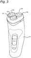
- FIG 3 illustrates a conventional rotary electric shaver 100 used for "dry" shaving.
- the shaver 100 comprises a body 101 and three heads 102 mounted in a face plate 104.
- Each of the heads comprises an outer cap 106, having a plurality of hair receiving slots 108 by which hairs may enter into the cap 106 and be cut by a rotating cutter beneath (see below).
- Figure 4 shows a detail through one of the heads 102 taken on line IV-IV in Figure 3 . Showing a hair H protruding through slot 108 of cap 106. Cutter 110 is shown moving in direction X to cut hair H by interaction with the slot 108 as is otherwise conventional. Figure 4 also shows the manner in which the skin S bulges into the slots 108 at B. In this view, the head 102 is moving in the direction M which corresponds to the direction X. The bulge B is therefore pushed against one side of the slot 108. It will however be understood that the cutter 110 rotates and its local direction of movement X does not therefore always correspond to the direction of movement M of the head 102 across the skin S.
- the skin S may become damaged by contact with the cutter 110. This damage may be reduced by various means, including increasing the thickness of the cap 106 and reducing the width of the slots 108. Most of these adaptations have a negative effect on the closeness of the ultimate shave that can be achieved.
- Figure 5 shows a schematic cross section through part of a rotary shaver 100A according to an embodiment of the present invention. Like elements to those of Figures 3 and 4 will be designated with like numerals.
- the face plate 104 is provided with electro-adhesive elements 122.
- the electro-adhesive elements 122 each comprise a plurality of electrodes 124 embedded in an insulating layer 126 in the same manner as those described above in relation to Figure 2 .
- Alternate electrodes 124', 124" are connected to +ive and -ive terminals of a DC voltage source 128. By connecting the voltage source 128, the electrodes 24 become charged and induce a local charge onto the skin S, which is thus attracted by electrostatic force towards the element 122.
- a sensor 130 is located on the face plate 104 for determining the degree of skin doming.
- the sensor 130 is an IR photodiode which operates together with an IR LED 132 to determine the bulging of the skin S through the slots 108 in the cap 106.
- the sensor 130 and LED 132 are both connected to a controller 134, which includes appropriate circuitry for processing their signals.
- the LED 132 emits IR light, which is reflected by the skin S.
- the controller 134 is set to determine an amount of bulge B and issue a signal to the voltage source 128 to increase the applied voltage to the electrodes 124 in order to adjust the electro-adhesive force as required.
- bulging is measured through the cap but it is understood that this may be measured at various positions including at a recess formed in the face plate, ahead of the face plate or between the face plate and the cap or foil.
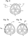
- Figure 6 shows a schematic frontal view of the face plate 104 of a rotary shaver 100B according to a further embodiment of the invention. Like elements to those of Figures 3 and 5 are given like references.
- Figure 6 differs from the embodiment of Figure 5 by the presence of a plurality of electro-adhesive elements 122 distributed around the periphery of the face plate 104 and an optical direction sensor 138 which in this embodiment is located at the centre of the face plate.
- the optical sensor 138 is operatively connected to the controller 134.
- Figures 7A and 7B illustrate frontal views of the face plate 104 of Figure 6 during operation of the shaver 100B.
- the optical sensor 138 takes images at a frequency of around 30Hz and the controller 134 calculates a motion vector from the differences between successive images.
- the controller 134 uses the motion vector to determine the direction and speed of movement M. Based on this measurement, it increases the attractive force of the electro-adhesive elements 122 that are located ahead of the heads 102 and it decreases the attractive force of the elements 122 that are located behind the heads 102, relative to the direction of movement M. The skin is thus held tight and skin doming is reduced.
Description
- The present invention relates to shavers and more specifically to shavers capable of adapting in use to improve the shaving effect. The invention applies to shavers having both stationary and moveable cutting elements and further relates to methods of operation of such devices.
- In shaving it is of interest to control the engagement of a cutting element with the skin to achieve the best and most consistent shaving experience whilst maintaining safety and comfort. The degree to which the skin bulges ahead of a blade or cutting element is termed doming. Increasing the shaving pressure may improve the shaving closeness but can also increase doming. As doming increases, the likelihood that the cutting element will damage the skin also increases. The doming of the skin in a shaving system is therefore of fundamental importance to a shaving experience.
- Skin doming for a particular shaving system depends on the system geometry and materials used. It additionally varies due to changes in shaving pressure, speed, direction, area of the body and individual variation of a person's skin properties. There is thus considerable variation in terms of the risk of cutting and the shaving closeness that can be achieved without damaging skin or causing discomfort.
- In wet shaving, skin doming is generally controlled by adding a rubbery skin stretcher that increases skin friction. This is located in front of the cutting element, the wet-shaving razor usually having one clear direction of use over the skin. By stretching the skin taut, its ability to dome ahead of the cutting element or blade is reduced. A lubricity strip may also be placed behind the cutting element or blade, which further enhances the stretching effect on the skin. Devices have also been proposed that actively seek to stretch the skin as described in
EP1697095 . - In dry shaving, the shaver is frequently moved in multiple directions over the skin. This means that in rotary dry shaving or in linear foil electric shaving the guard or skin engaging surface is limited by having to allow for movement over the skin in any direction.
- A skin stretching solution of the type used in wet shaving systems is therefore not possible. In certain designs, the guard member (a foil or a shaving cap) or a skin engaging surface of the shaving head may be provided with stretching elements in the form of rings or protrusions which assist in supporting the skin and controlling the pressure and angle at which it comes into contact with the cutting element. A rotary shaver provided with a skin stretching element is disclosed in
WO02051598 -
DE605623 discloses a shaving device having a rotating hair-cutting disc accommodated in a housing. The housing has a hair-entry opening in the form of an annular segment, via which hairs can be exposed to the rotating hair-cutting disc. In front of the hair-entry opening a suction opening is arranged concentrically with the hair-entry opening. During use a suction force is applied via the suction opening to the skin in front of the hair-entry opening. The suction force stretches the skin to prevent the skin from being cut by the rotating hair-cutting disc. The pressure in the suction opening can be controlled by the user by means of an operating member which is coupled to a piston. - It would therefore be desirable to provide a shaver that allowed better control of skin doming irrespective of the direction of movement of the shaver across the skin.
- According to the invention there is provided a shaver comprising a skin engaging portion and a cutting element, wherein the skin engaging portion comprises a force-generating member configured and arranged to generate a force of attraction to the skin of a user and the shaver further comprising a control element that can selectively adjust said force of attraction during use, wherein the control element comprises a sensor for measuring a parameter associated with the skin and a controller for selectively adapting the force of attraction in response to a measured property of the parameter. As a result of an increase in the force of attraction, the local frictional force during movement across the skin will also be increased. This increased frictional force can be used to selectively stretch the skin and thus reduce skin doming. It will be understood that the frictional force between the skin-engaging surface and the skin will depend upon the coefficient of friction and upon the force applied by the user. Nevertheless, selectively increasing the frictional force in one region relative to other regions can take place independently of the overall force applied by the user. The sensor and the controller provide direct feedback based on real time measurements at the skin surface, which allows the force of attraction to be varied in order to improve the shaving effect.
- Various methods of locally varying the force of attraction may be envisaged, including the use of suction provided by small nozzles or openings in the skin engaging portion and a suitable source of vacuum. Nevertheless, according to a preferred embodiment of the invention, the force-generating member comprises an electro-adhesive element, which is attracted to the skin surface by electrostatic attraction. The principles of electrostatic attraction and electro-adhesion are well known and may be embodied in different forms according to the desired configuration and operation of the shaver. The basic principle of an electrostatic effect on the skin has been discovered and described by Mallinckrodt et al. in 1950 and published in "Perception by the skin of electrically induced vibrations", Science 118(3062: 277-278, 1953). More recently commercial embodiments have been developed allowing electro-adhesion to be used for various purposes including wall-climbing robots and the like.
- The electro-adhesive element may comprise charge-holding conductors or electrodes shielded from the skin by a thin insulator. The electrodes can be moulded into an otherwise non-conductive skin-engaging portion e.g. using a graphite or conducting filler within a composite body. Alternatively, they may be applied onto the skin engaging portion with an insulating lacquer layer (widely known for e.g. wire windings) applied to cover the electrodes. The arrangement can thus be made economically within the shape and constraints of the shaving system
- In one embodiment of the invention, the electrodes are charged with an alternating voltage, preferably to between 70V and 200V. The switching frequency may be adjusted according to the desired result and may typically be from 50 to 200Hz. Any leak current to the skin is in the micro Ampere range or below and not noticeable to the user.
- In an alternative embodiment of the invention, the electro-adhesive element comprises adjacent first and second electrodes connected to a DC source such that the first and second electrodes may be oppositely charged with respect to each other. This enables a DC voltage, not requiring switching, to induce a change in attraction to the surface by the skin
- Various parameters may be sensed and used for control of the force of attraction. In one preferred embodiment, the parameter may be indicative of a direction of movement of the skin-engaging portion with respect to the skin. This can allow the controller to adapt the force of attraction to ensure that a high force is present ahead of the cutting element compared to a force of attraction behind the cutting element. Various methods exist for detecting the shaving direction. An electrical switch may be provided, actuated by the friction and motion of the skin-engaging portion across the skin. In a more preferred embodiment, an optical sensor may be provided, arranged in the manner as commonly used in a computer mouse. The sensor takes images at a frequency of around 30Hz and calculates a motion vector from the deltas between successive images. The net motion vector is evaluated by or provided to the controller.
- Another parameter that may preferably be measured is a parameter indicative of a degree of doming of the skin ahead of the cutting element. A robust method of detecting the skin doming is to measure the actual doming or doming pressure directly. This can be achieved by placing a sensing probe in a relevant position between the skin-engaging portion and cutting element.
- In a simple form, the measuring device may be capable of distinguishing between two states of skin doming, e.g. high and low. The controller may be arranged to increase the force of attraction on detection of the degree of doming exceeding a predetermined value. This enables the skin stretcher to switch to high-friction or low-friction depending on the detected state. A sufficient steady-zone between the two states, either in time or in measured values, will avoid hysteresis and enable the system to be practical and have an actual benefit in reducing skin doming variations by attenuating extreme cases of doming. A higher resolution sensing arrangement will enable more optimal control systems, as are widely known from the field of feedback control technology.
- The actual sensor can be a piezo element that is in contact with the skin during shaving. This enables a force measurement even in a wet environment in a wet shaving system. An alternative, optical system may use a close-range IR proximity sensor. Even in the case of wet shaving using foam, this may provide a usable proxy value of skin doming. In a rotary or reciprocating system, skin doming may be measured in a recess in a face plate or alternatively through the slots formed in a foil or cap. A further alternative is a mechanical element, arranged to touch and trace over the skin just ahead of the blade, between the skin engaging portion (guard) and cutting element. This may be coupled to a potentiometer element to measure a skin doming value. The benefit of electrical measurement methods is that they enable direct feedback to the force-generating member.
- In a still further preferred embodiment, the skin-engaging portion comprises a plurality of force-generating members and the force of attraction of each force-generating member or group of force-generating members can be selectively adapted independently of the other force-generating members. Such an arrangement is particularly useful for shavers that can be advanced in different directions during cutting, such as rotary or reciprocating shavers as it specifically allows those portions to be adapted that are ahead of the cutting element. Such shavers may be characterized as those where the cutting element is moveable with respect to the skin-engaging portion to perform cutting of hairs during shaving. A controller and direction sensor as described above may be arranged to selectively adjust the force of attraction of those force-generating members located ahead of the cutting element in a measured direction of movement of the shaver across the skin. Preferably, the shaver comprises a plurality of cutting elements, each comprising a rotary shaving head having a rotating cutter. The heads may be mounted to a face plate and the force-generating members that can be selectively activated are located in regions of the face plate surrounding the rotary shaving heads. It will however also be understood that skin engaging regions of the cap or head of a rotary shaver may also be provided with such force-generating members.
- In a particular embodiment of the invention, the skin engaging portion of the shaver comprises a face plate in which a plurality of cutting elements are located, each comprising a rotary shaving head having a rotating cutter, and a plurality of force-generating members are provided, distributed around a periphery of the face plate, wherein the controller is operable in response to a direction of movement measured by the sensor to selectively increase the force of attraction of those force generating members located ahead of the rotary shaving heads with respect to the measured direction of movement.
- As mentioned above however, the shaver may also be a wet-shaver having one or more elongate blades mounted in a guard. In this case, the regions that can be selectively activated may be located on the skin-engaging portion of the guard.
- The invention also relates to a method of controlling operation of a shaver comprising moving a skin engaging portion of the shaver across the skin of a user in a direction of motion, whereby the skin engaging portion engages the skin and a cutting element engages hairs to be cut, and adjusting a force of attraction between the skin and at least a region of the skin engaging portion during said movement, in order to adjust a degree of stretching of the skin ahead of the cutting element, wherein the method further comprises measuring a parameter associated with the skin, and selectively adapting the force of attraction in response to a measured property of the parameter. As described above, by stretching the skin in this manner, doming can be reduced and improved comfort may be achieved.
- In one preferred form, the method comprises measuring a parameter indicative of skin doming ahead of the cutting element and selectively adjusting the force of attraction to adjust such skin doming.
- The method may also or alternatively comprise measuring a parameter indicative of the direction of motion and selectively increasing the force of attraction ahead of the cutting element, whereby doming may controlled irrespective of a direction of movement of the shaver.
- The features and advantages of the invention will be appreciated upon reference to the following drawings of a number of exemplary embodiments, in which:
-
Figure 1 shows a schematic cross-section of a conventional wet shaver; -
Figure 2 shows a schematic cross-section of a shaver according to a first embodiment of the present invention -
Figure 3 shows a perspective view of a conventional rotary shaver; -
Figure 4 shows a partial cross-section through the shaver ofFigure 3 along line IV-IV; -
Figure 5 shows a schematic cross-section through a rotary shaver according to the present invention; -
Figure 6 shows a frontal view of the face plate of a rotary shaver according to a second embodiment of the invention; and -
Figures 7A and 7B show views of the shaver ofFigure 6 during use. -
Figure 1 shows a schematic cross-sectional view of a conventionalwet shaver 1 comprising ahandle 2, a guard 4 and a pair ofcutting blades 6 mounted within the guard 4. The guard has a skin-engagingportion 8 and the cutting edges 10 of theblades 6 lie approximately in the plane of the skin-engagingportion 8. - During use, the skin-engaging
portion 8 of theshaver 1 is pressed against the user's skin S and moved in a direction M. Due to the pressure exerted by theblades 6 and its inherent elasticity, the skin S is caused to form a bulge B extending towards the guard 4 in those areas where it is unsupported, such as between theblades 6 and between theblades 6 and the guard 4. This effect is known as doming. In order to reduce doming, the guard is provided with a skin-stretcher 12 ahead of theblades 6 and alubricity strip 14 behind theblades 6. The skin-stretcher 12 is a region of increased friction comprising a ribbed rubberlike portion. Thelubricity strip 14 comprises a lubricious water-soluble polymer and provides a region of reduced friction. The net effect of these regions is to cause the skin to be stretched or held taut in the area of the blades, thus reducing the amount of doming. -
Figure 2 shows a wet shaver 20A according to a first embodiment of the present invention in a schematic cross-sectional view similar to that ofFigure 1 , in which like elements are given similar references. The shaver 20 is generally similar to theconventional shaver 1, with the exception of the skin-stretcher 12, which is replaced by an electro-adhesive element 22. The electro-adhesive element 22 comprises a plurality ofelectrodes 24 embedded in an insulatinglayer 26.Alternate electrodes 24', 24" are connected to +ive and - ive terminals of aDC voltage source 28. By connecting thevoltage source 28, theelectrodes 24 become charged and induce a local charge onto the skin S, which is thus attracted by electrostatic force towards theelement 22.Figure 2 also shows a sensor 30 located on the guard 4 for determining the degree of skin doming ahead of theblades 6. The sensor 30 is an infrared (IR) photodiode capable of detecting IR radiation. An IR light source in the form of anLED 32 is also located within the guard 4 at a slight distance from the sensor 30. The sensor 30 andLED 32 are both connected to acontroller 34, which includes appropriate circuitry for processing their signals. In use, theLED 32 emits IR light, which is reflected by the skin S. Thecontroller 34 is set to determine when a bulge B is formed. At this point, a signal is given to thevoltage source 28 to increase the applied voltage to theelectrodes 24 in order to increase the electro-adhesive force. This results in increased friction ahead of theblades 6 and greater stretching of the skin S, leading to a reduction in the size of the bulge B. Although a simple control principle has been described, the skilled person will be well aware that more complex sensor circuitry may be used to evaluate proximity by modulation and triangulation techniques and that alternative acoustic, piezo-electric and tactile sensors may also be employed. -
Figure 3 illustrates a conventional rotaryelectric shaver 100 used for "dry" shaving. Theshaver 100 comprises abody 101 and threeheads 102 mounted in aface plate 104. Each of the heads comprises anouter cap 106, having a plurality ofhair receiving slots 108 by which hairs may enter into thecap 106 and be cut by a rotating cutter beneath (see below). -
Figure 4 shows a detail through one of theheads 102 taken on line IV-IV inFigure 3 . Showing a hair H protruding throughslot 108 ofcap 106.Cutter 110 is shown moving in direction X to cut hair H by interaction with theslot 108 as is otherwise conventional.Figure 4 also shows the manner in which the skin S bulges into theslots 108 at B. In this view, thehead 102 is moving in the direction M which corresponds to the direction X. The bulge B is therefore pushed against one side of theslot 108. It will however be understood that thecutter 110 rotates and its local direction of movement X does not therefore always correspond to the direction of movement M of thehead 102 across the skin S. - Due to the bulge B of skin into the
slots 108, the skin S may become damaged by contact with thecutter 110. This damage may be reduced by various means, including increasing the thickness of thecap 106 and reducing the width of theslots 108. Most of these adaptations have a negative effect on the closeness of the ultimate shave that can be achieved. -
Figure 5 shows a schematic cross section through part of arotary shaver 100A according to an embodiment of the present invention. Like elements to those ofFigures 3 and4 will be designated with like numerals. - According to
Figure 5 , theface plate 104 is provided with electro-adhesive elements 122. The electro-adhesive elements 122 each comprise a plurality ofelectrodes 124 embedded in an insulatinglayer 126 in the same manner as those described above in relation toFigure 2 .Alternate electrodes 124', 124" are connected to +ive and -ive terminals of aDC voltage source 128. By connecting thevoltage source 128, theelectrodes 24 become charged and induce a local charge onto the skin S, which is thus attracted by electrostatic force towards theelement 122. - Also similarly to
Figure 2 , a sensor 130 is located on theface plate 104 for determining the degree of skin doming. The sensor 130 is an IR photodiode which operates together with anIR LED 132 to determine the bulging of the skin S through theslots 108 in thecap 106. The sensor 130 andLED 132 are both connected to acontroller 134, which includes appropriate circuitry for processing their signals. In use, theLED 132 emits IR light, which is reflected by the skin S. Thecontroller 134 is set to determine an amount of bulge B and issue a signal to thevoltage source 128 to increase the applied voltage to theelectrodes 124 in order to adjust the electro-adhesive force as required. In the present embodiment, bulging is measured through the cap but it is understood that this may be measured at various positions including at a recess formed in the face plate, ahead of the face plate or between the face plate and the cap or foil. - Although a simple control principle has been described, the skilled person will be well aware that more complex sensor circuitry may be used to evaluate proximity by modulation and triangulation techniques and that alternative acoustic, piezo-electric and tactile sensors may also be employed.
-
Figure 6 shows a schematic frontal view of theface plate 104 of arotary shaver 100B according to a further embodiment of the invention. Like elements to those ofFigures 3 and5 are given like references. -
Figure 6 differs from the embodiment ofFigure 5 by the presence of a plurality of electro-adhesive elements 122 distributed around the periphery of theface plate 104 and anoptical direction sensor 138 which in this embodiment is located at the centre of the face plate. Theoptical sensor 138 is operatively connected to thecontroller 134. -
Figures 7A and 7B illustrate frontal views of theface plate 104 ofFigure 6 during operation of theshaver 100B. During use, theoptical sensor 138 takes images at a frequency of around 30Hz and thecontroller 134 calculates a motion vector from the differences between successive images. Thecontroller 134 uses the motion vector to determine the direction and speed of movement M. Based on this measurement, it increases the attractive force of the electro-adhesive elements 122 that are located ahead of theheads 102 and it decreases the attractive force of theelements 122 that are located behind theheads 102, relative to the direction of movement M. The skin is thus held tight and skin doming is reduced. - Thus, the invention has been described by reference to certain embodiments discussed above. It will be recognized that these embodiments are susceptible to various modifications and alternative forms well known to those of skill in the art. In particular, the arrangement of
Figures 5 to 7 may also be applied to reciprocating shavers using a foil instead of the cap disclosed.
Claims (14)
- A shaver (20A, 100A, 100B) comprising a skin engaging portion and a cutting element (6, 102), wherein the skin engaging portion comprises a force-generating member (22, 122) configured and arranged to generate a force of attraction to the skin (S) of a user, the shaver further comprising a control element that can selectively adjust said force of attraction during use, characterized in that the control element comprises a sensor (30, 32; 130, 132; 138) for measuring a parameter associated with the skin (S) and a controller (34, 134) configured to selectively adapting the force of attraction in response to a measured property of the parameter.
- The shaver (20A, 100A, 100b) according to claim 1, wherein the force-generating member comprises an electro-adhesive element (22, 122).
- The shaver according to claim 2, wherein the electro-adhesive element comprises charge-holding electrodes connected to an alternating voltage source and covered by an insulating layer to prevent contact between the electrodes and the skin.
- The shaver (20A, 100A) according to claim 2, wherein the electro-adhesive element (22, 122) comprises adjacent first and second electrodes (24, 24', 24"; 124', 124") covered by an insulating layer (26, 126) to prevent contact between the electrodes and the skin (S) and connected to a DC source (28, 128) such that the first and second electrodes may be oppositely charged with respect to each other.
- The shaver (20A, 100A, 100B) according to claim 1, wherein the parameter is indicative of a direction of movement (M) of the skin engaging portion with respect to the skin (S).
- The shaver (20A, 100A, 100B) according to claim 1, wherein the parameter is indicative of a degree of doming (B) of the skin (S) ahead of the cutting element (6, 110).
- The shaver (20A, 100A) according to claim 6, wherein the controller (34, 134) is arranged to increase the force of attraction on detection of the degree of doming (B) exceeding a predetermined value.
- The shaver (100B) according to any preceding claim, wherein the skin engaging portion comprises a plurality of force-generating members (122) and the force of attraction of each force-generating member can be selectively adapted independently of the other force-generating members.
- The shaver (100B) according to claim 8, wherein the controller (134) is arranged to selectively adjust the force of attraction of those force-generating members (122) located ahead of the cutting element (102) in a measured direction of movement (M) of the shaver across the skin.
- The shaver (20A, 100A, 100B) according to any preceding claim, wherein the cutting element (6, 102) is moveable with respect to the skin engaging portion to perform cutting of hairs (H) during shaving.
- The shaver (100A, 100B) according to claim 10, wherein the shaver comprises a plurality of cutting elements (102) each comprising a rotary shaving head having a rotating cutter (110).
- The shaver (100A, 100b) according to claim 5, wherein the skin engaging portion comprises a face plate (104) in which a plurality of cutting elements (102) are located, each comprising a rotary shaving head having a rotating cutter (110), and a plurality of force-generating members (122) are provided, distributed around a periphery of the face plate, wherein the controller (134) is operable in response to a direction of movement (M) measured by the sensor (138) to selectively increase the force of attraction of those force generating members located ahead of the rotary shaving heads with respect to the measured direction of movement.
- The shaver (20A) according to any of claims 1 to 9, wherein the shaver is a wet-shaver having one or more elongate blades (6) mounted in a guard (4).
- A method of controlling operation of a shaver (20A, 100A, 100B) comprising:- moving a skin engaging portion of the shaver across the skin (S) of a user in a direction of motion (M), whereby the skin engaging portion engages the skin and a cutting element (6, 102) engages hairs (H) to be cut;- adjusting a force of attraction between the skin and at least a region of the skin engaging portion during said movement, in order to adjust a degree of stretching of the skin ahead of the cutting element;characterized in that the method further comprises:- measuring a parameter associated with the skin (S); and- selectively adapting the force of attraction in response to a measured property of the parameter.
Priority Applications (1)
| Application Number | Priority Date | Filing Date | Title |
|---|---|---|---|
| PL13720578T PL2828046T3 (en) | 2012-03-22 | 2013-03-13 | Shaver having adaptive skin engaging surface |
Applications Claiming Priority (2)
| Application Number | Priority Date | Filing Date | Title |
|---|---|---|---|
| US201261614147P | 2012-03-22 | 2012-03-22 | |
| PCT/IB2013/051988 WO2013140309A1 (en) | 2012-03-22 | 2013-03-13 | Shaver having adaptive surface |
Publications (2)
| Publication Number | Publication Date |
|---|---|
| EP2828046A1 EP2828046A1 (en) | 2015-01-28 |
| EP2828046B1 true EP2828046B1 (en) | 2018-10-03 |
Family
ID=48289542
Family Applications (1)
| Application Number | Title | Priority Date | Filing Date |
|---|---|---|---|
| EP13720578.7A Active EP2828046B1 (en) | 2012-03-22 | 2013-03-13 | Shaver having adaptive skin engaging surface |
Country Status (9)
| Country | Link |
|---|---|
| US (1) | US9821479B2 (en) |
| EP (1) | EP2828046B1 (en) |
| JP (1) | JP6113825B2 (en) |
| CN (1) | CN104185537B (en) |
| BR (1) | BR112014023001B1 (en) |
| ES (1) | ES2702037T3 (en) |
| PL (1) | PL2828046T3 (en) |
| RU (1) | RU2635502C2 (en) |
| WO (1) | WO2013140309A1 (en) |
Families Citing this family (15)
| Publication number | Priority date | Publication date | Assignee | Title |
|---|---|---|---|---|
| US10131061B2 (en) * | 2013-05-30 | 2018-11-20 | Koninklijke Philips N.V. | Device and system for treating hair and/or skin |
| US10179418B2 (en) | 2014-09-26 | 2019-01-15 | Koninklijke Philips N.V. | Shaving device for skin hairs |
| US10653224B2 (en) | 2014-12-01 | 2020-05-19 | Koninklijke Philips N.V. | Hair removal apparatus |
| US10932541B2 (en) | 2014-12-11 | 2021-03-02 | Koninklijke Philips N.V. | Skin treatment device |
| ES2881628T3 (en) * | 2015-01-15 | 2021-11-30 | Koninklijke Philips Nv | Hair cutting device |
| JP6840730B2 (en) * | 2015-08-24 | 2021-03-10 | コーニンクレッカ フィリップス エヌ ヴェKoninklijke Philips N.V. | Step-by-step advice for optimal use of shaving devices |
| AT518027A1 (en) * | 2015-12-01 | 2017-06-15 | Payer Int Tech Gmbh | Hair clipper |
| RU2740346C2 (en) * | 2016-06-20 | 2021-01-13 | Конинклейке Филипс Н.В. | Friction control device and method |
| EP3546149B1 (en) | 2018-03-27 | 2021-05-12 | Braun GmbH | Hair removal device |
| EP3546148B1 (en) * | 2018-03-27 | 2022-01-12 | Braun GmbH | Personal care device |
| EP3546150B1 (en) | 2018-03-27 | 2021-10-27 | Braun GmbH | Personal care device |
| EP3546151A1 (en) | 2018-03-27 | 2019-10-02 | Braun GmbH | Personal care device |
| US11673282B2 (en) * | 2020-07-02 | 2023-06-13 | The Gillette Company Llc | Sensor-based shaving systems and methods of analyzing a user's shave event for determining a unique threshold value of the user |
| US20220063117A1 (en) * | 2020-08-25 | 2022-03-03 | Moses Brown | Hair Cutting System and Methods of Use |
| EP4124422A1 (en) * | 2021-07-29 | 2023-02-01 | Braun GmbH | Personal care device |
Family Cites Families (30)
| Publication number | Priority date | Publication date | Assignee | Title |
|---|---|---|---|---|
| DE605623C (en) | 1933-07-04 | 1935-03-23 | Otto Beuth | Device for suctioning the skin on shaving machines |
| US3316633A (en) * | 1965-10-14 | 1967-05-02 | Gen Medical Co | Electrical hair-erector shaver |
| US3373747A (en) * | 1967-04-28 | 1968-03-19 | Gen Medical Co | Electrical muscle stimulator device and razor attachment therefor |
| DE2133113A1 (en) | 1971-07-02 | 1973-01-18 | Braun Ag | CATCHING ELECTRODE FOR DEVICES FOR HAIR DUST ROLLING IN DRY SHAVERS |
| US4089110A (en) | 1976-03-08 | 1978-05-16 | Rasco Darius K | Shaving means |
| JPS6041960B2 (en) * | 1980-09-30 | 1985-09-19 | 松下電工株式会社 | Electric razor with head for stretching the skin |
| JPS57206477A (en) | 1981-06-15 | 1982-12-17 | Matsushita Electric Works Ltd | Electric razor |
| US4896420A (en) * | 1987-10-07 | 1990-01-30 | Remington Products, Inc. | Electric shaver |
| ATE198851T1 (en) * | 1994-07-01 | 2001-02-15 | Gillette Co | PART OF A SHAVING UNIT THAT CONTACTS THE SKIN |
| US6125542A (en) * | 1998-04-30 | 2000-10-03 | Somma; Dante | Self-powered razor head |
| US6070327A (en) * | 1999-02-19 | 2000-06-06 | Taso; Selim | Manual shaving apparatus |
| ATE311274T1 (en) | 2000-12-22 | 2005-12-15 | Koninkl Philips Electronics Nv | AUXILIARY PART FOR ELECTRIC SHAVERS |
| DE20115818U1 (en) * | 2001-09-26 | 2002-04-18 | Merlaku Kastriot | Rasierhilfsgerät |
| US8627573B2 (en) * | 2002-10-05 | 2014-01-14 | Braun Gmbh | Hair-removing device |
| DE602004016212D1 (en) * | 2003-12-10 | 2008-10-09 | Koninkl Philips Electronics Nv | SHAVING HEAD WITH SCISSORS |
| JP2006289098A (en) | 2005-04-12 | 2006-10-26 | Inolase 2002 Ltd | Apparatus for vacuum-assisted light-based treatment of skin |
| DE102006004675A1 (en) | 2006-02-02 | 2007-08-09 | Braun Gmbh | Electric razor |
| US7551419B2 (en) | 2006-06-05 | 2009-06-23 | Sri International | Electroadhesion |
| WO2008091625A2 (en) * | 2007-01-22 | 2008-07-31 | Syneron Medical Ltd. | Hair removal devices and methods |
| ES2395454T3 (en) * | 2008-01-17 | 2013-02-12 | Syneron Medical Ltd. | A device for hair removal for personal use and the method of use thereof |
| DE102008032389A1 (en) * | 2008-07-09 | 2010-01-14 | Richard Seidenbusch | Disposable electric razor, has hand part comprising energy source and pole contact for head part, superior double track skin contact strip forming bridge field and pole, and blades forming antipole |
| DE102008048725A1 (en) | 2008-09-24 | 2010-03-25 | Braun Gmbh | Hair removal device with skin preparation device |
| FR2939633B1 (en) | 2008-12-11 | 2011-01-21 | Seb Sa | HAND CARE APPARATUS FOR BODY CARE WITH PRESENCE DETECTION. |
| PL2456383T3 (en) | 2009-07-23 | 2017-10-31 | Koninklijke Philips Nv | Optical blade and hair cutting device |
| BR112012007488A2 (en) | 2009-10-05 | 2020-07-21 | Koninklijke Philips Electronics N. V | razor blade unit shaver device |
| WO2011067761A1 (en) * | 2009-12-06 | 2011-06-09 | Syneron Medical Ltd. | A method and apparatus for personal skin treatment |
| JP2011125410A (en) * | 2009-12-15 | 2011-06-30 | Takao Ikeda | Electric razor |
| CN201941027U (en) * | 2011-03-02 | 2011-08-24 | 钱叶亮 | Intelligent safe shaver |
| RU2612866C2 (en) * | 2011-12-22 | 2017-03-13 | Конинклейке Филипс Н.В. | Hair cutting device |
| US9084891B2 (en) * | 2012-02-06 | 2015-07-21 | David Aberizk | Pilomotor effect stimulating device and method |
-
2013
- 2013-03-13 WO PCT/IB2013/051988 patent/WO2013140309A1/en active Application Filing
- 2013-03-13 PL PL13720578T patent/PL2828046T3/en unknown
- 2013-03-13 JP JP2015501022A patent/JP6113825B2/en active Active
- 2013-03-13 BR BR112014023001-3A patent/BR112014023001B1/en not_active IP Right Cessation
- 2013-03-13 ES ES13720578T patent/ES2702037T3/en active Active
- 2013-03-13 RU RU2014142553A patent/RU2635502C2/en active
- 2013-03-13 CN CN201380015523.7A patent/CN104185537B/en active Active
- 2013-03-13 EP EP13720578.7A patent/EP2828046B1/en active Active
- 2013-03-13 US US14/383,592 patent/US9821479B2/en active Active
Non-Patent Citations (1)
| Title |
|---|
| None * |
Also Published As
| Publication number | Publication date |
|---|---|
| ES2702037T3 (en) | 2019-02-27 |
| US9821479B2 (en) | 2017-11-21 |
| US20150128776A1 (en) | 2015-05-14 |
| WO2013140309A1 (en) | 2013-09-26 |
| BR112014023001B1 (en) | 2020-09-29 |
| JP2015510808A (en) | 2015-04-13 |
| EP2828046A1 (en) | 2015-01-28 |
| RU2635502C2 (en) | 2017-11-13 |
| CN104185537B (en) | 2016-08-24 |
| JP6113825B2 (en) | 2017-04-12 |
| PL2828046T3 (en) | 2019-03-29 |
| CN104185537A (en) | 2014-12-03 |
| RU2014142553A (en) | 2016-05-20 |
Similar Documents
| Publication | Publication Date | Title |
|---|---|---|
| EP2828046B1 (en) | Shaver having adaptive skin engaging surface | |
| EP1556191B1 (en) | Razor system having razor sensors | |
| EP3230020B1 (en) | Skin treatment device | |
| EP3065920B1 (en) | A system for treating a part of a body | |
| US11910901B2 (en) | Hair removal apparatus | |
| EP3003652B1 (en) | Device and system for treating hair and/or skin | |
| JP5377980B2 (en) | Electric shaver | |
| RU2017114354A (en) | HAIR Razor | |
| KR20060121176A (en) | Safety razors | |
| JP2015510808A5 (en) | ||
| WO2009066218A1 (en) | Safety razor with multi-pivot blade unit | |
| TWI341239B (en) | Improved electric shaver | |
| WO2022168782A1 (en) | Electric shaver | |
| EP4311637A1 (en) | Shaving head |
Legal Events
| Date | Code | Title | Description |
|---|---|---|---|
| PUAI | Public reference made under article 153(3) epc to a published international application that has entered the european phase |
Free format text: ORIGINAL CODE: 0009012 |
|
| 17P | Request for examination filed |
Effective date: 20141022 |
|
| AK | Designated contracting states |
Kind code of ref document: A1 Designated state(s): AL AT BE BG CH CY CZ DE DK EE ES FI FR GB GR HR HU IE IS IT LI LT LU LV MC MK MT NL NO PL PT RO RS SE SI SK SM TR |
|
| AX | Request for extension of the european patent |
Extension state: BA ME |
|
| DAX | Request for extension of the european patent (deleted) | ||
| GRAP | Despatch of communication of intention to grant a patent |
Free format text: ORIGINAL CODE: EPIDOSNIGR1 |
|
| STAA | Information on the status of an ep patent application or granted ep patent |
Free format text: STATUS: GRANT OF PATENT IS INTENDED |
|
| INTG | Intention to grant announced |
Effective date: 20180425 |
|
| GRAS | Grant fee paid |
Free format text: ORIGINAL CODE: EPIDOSNIGR3 |
|
| GRAA | (expected) grant |
Free format text: ORIGINAL CODE: 0009210 |
|
| STAA | Information on the status of an ep patent application or granted ep patent |
Free format text: STATUS: THE PATENT HAS BEEN GRANTED |
|
| AK | Designated contracting states |
Kind code of ref document: B1 Designated state(s): AL AT BE BG CH CY CZ DE DK EE ES FI FR GB GR HR HU IE IS IT LI LT LU LV MC MK MT NL NO PL PT RO RS SE SI SK SM TR |
|
| REG | Reference to a national code |
Ref country code: GB Ref legal event code: FG4D |
|
| REG | Reference to a national code |
Ref country code: CH Ref legal event code: EP Ref country code: AT Ref legal event code: REF Ref document number: 1048113 Country of ref document: AT Kind code of ref document: T Effective date: 20181015 |
|
| REG | Reference to a national code |
Ref country code: IE Ref legal event code: FG4D Ref country code: DE Ref legal event code: R096 Ref document number: 602013044454 Country of ref document: DE |
|
| REG | Reference to a national code |
Ref country code: NL Ref legal event code: FP |
|
| REG | Reference to a national code |
Ref country code: LT Ref legal event code: MG4D |
|
| REG | Reference to a national code |
Ref country code: ES Ref legal event code: FG2A Ref document number: 2702037 Country of ref document: ES Kind code of ref document: T3 Effective date: 20190227 |
|
| REG | Reference to a national code |
Ref country code: AT Ref legal event code: MK05 Ref document number: 1048113 Country of ref document: AT Kind code of ref document: T Effective date: 20181003 |
|
| PG25 | Lapsed in a contracting state [announced via postgrant information from national office to epo] |
Ref country code: LT Free format text: LAPSE BECAUSE OF FAILURE TO SUBMIT A TRANSLATION OF THE DESCRIPTION OR TO PAY THE FEE WITHIN THE PRESCRIBED TIME-LIMIT Effective date: 20181003 Ref country code: NO Free format text: LAPSE BECAUSE OF FAILURE TO SUBMIT A TRANSLATION OF THE DESCRIPTION OR TO PAY THE FEE WITHIN THE PRESCRIBED TIME-LIMIT Effective date: 20190103 Ref country code: CZ Free format text: LAPSE BECAUSE OF FAILURE TO SUBMIT A TRANSLATION OF THE DESCRIPTION OR TO PAY THE FEE WITHIN THE PRESCRIBED TIME-LIMIT Effective date: 20181003 Ref country code: AT Free format text: LAPSE BECAUSE OF FAILURE TO SUBMIT A TRANSLATION OF THE DESCRIPTION OR TO PAY THE FEE WITHIN THE PRESCRIBED TIME-LIMIT Effective date: 20181003 Ref country code: IS Free format text: LAPSE BECAUSE OF FAILURE TO SUBMIT A TRANSLATION OF THE DESCRIPTION OR TO PAY THE FEE WITHIN THE PRESCRIBED TIME-LIMIT Effective date: 20190203 Ref country code: FI Free format text: LAPSE BECAUSE OF FAILURE TO SUBMIT A TRANSLATION OF THE DESCRIPTION OR TO PAY THE FEE WITHIN THE PRESCRIBED TIME-LIMIT Effective date: 20181003 Ref country code: BG Free format text: LAPSE BECAUSE OF FAILURE TO SUBMIT A TRANSLATION OF THE DESCRIPTION OR TO PAY THE FEE WITHIN THE PRESCRIBED TIME-LIMIT Effective date: 20190103 Ref country code: HR Free format text: LAPSE BECAUSE OF FAILURE TO SUBMIT A TRANSLATION OF THE DESCRIPTION OR TO PAY THE FEE WITHIN THE PRESCRIBED TIME-LIMIT Effective date: 20181003 Ref country code: LV Free format text: LAPSE BECAUSE OF FAILURE TO SUBMIT A TRANSLATION OF THE DESCRIPTION OR TO PAY THE FEE WITHIN THE PRESCRIBED TIME-LIMIT Effective date: 20181003 |
|
| PG25 | Lapsed in a contracting state [announced via postgrant information from national office to epo] |
Ref country code: RS Free format text: LAPSE BECAUSE OF FAILURE TO SUBMIT A TRANSLATION OF THE DESCRIPTION OR TO PAY THE FEE WITHIN THE PRESCRIBED TIME-LIMIT Effective date: 20181003 Ref country code: AL Free format text: LAPSE BECAUSE OF FAILURE TO SUBMIT A TRANSLATION OF THE DESCRIPTION OR TO PAY THE FEE WITHIN THE PRESCRIBED TIME-LIMIT Effective date: 20181003 Ref country code: SE Free format text: LAPSE BECAUSE OF FAILURE TO SUBMIT A TRANSLATION OF THE DESCRIPTION OR TO PAY THE FEE WITHIN THE PRESCRIBED TIME-LIMIT Effective date: 20181003 Ref country code: PT Free format text: LAPSE BECAUSE OF FAILURE TO SUBMIT A TRANSLATION OF THE DESCRIPTION OR TO PAY THE FEE WITHIN THE PRESCRIBED TIME-LIMIT Effective date: 20190203 Ref country code: GR Free format text: LAPSE BECAUSE OF FAILURE TO SUBMIT A TRANSLATION OF THE DESCRIPTION OR TO PAY THE FEE WITHIN THE PRESCRIBED TIME-LIMIT Effective date: 20190104 |
|
| REG | Reference to a national code |
Ref country code: DE Ref legal event code: R097 Ref document number: 602013044454 Country of ref document: DE |
|
| PG25 | Lapsed in a contracting state [announced via postgrant information from national office to epo] |
Ref country code: DK Free format text: LAPSE BECAUSE OF FAILURE TO SUBMIT A TRANSLATION OF THE DESCRIPTION OR TO PAY THE FEE WITHIN THE PRESCRIBED TIME-LIMIT Effective date: 20181003 |
|
| PLBE | No opposition filed within time limit |
Free format text: ORIGINAL CODE: 0009261 |
|
| STAA | Information on the status of an ep patent application or granted ep patent |
Free format text: STATUS: NO OPPOSITION FILED WITHIN TIME LIMIT |
|
| PG25 | Lapsed in a contracting state [announced via postgrant information from national office to epo] |
Ref country code: RO Free format text: LAPSE BECAUSE OF FAILURE TO SUBMIT A TRANSLATION OF THE DESCRIPTION OR TO PAY THE FEE WITHIN THE PRESCRIBED TIME-LIMIT Effective date: 20181003 Ref country code: SM Free format text: LAPSE BECAUSE OF FAILURE TO SUBMIT A TRANSLATION OF THE DESCRIPTION OR TO PAY THE FEE WITHIN THE PRESCRIBED TIME-LIMIT Effective date: 20181003 Ref country code: EE Free format text: LAPSE BECAUSE OF FAILURE TO SUBMIT A TRANSLATION OF THE DESCRIPTION OR TO PAY THE FEE WITHIN THE PRESCRIBED TIME-LIMIT Effective date: 20181003 Ref country code: SK Free format text: LAPSE BECAUSE OF FAILURE TO SUBMIT A TRANSLATION OF THE DESCRIPTION OR TO PAY THE FEE WITHIN THE PRESCRIBED TIME-LIMIT Effective date: 20181003 |
|
| 26N | No opposition filed |
Effective date: 20190704 |
|
| PG25 | Lapsed in a contracting state [announced via postgrant information from national office to epo] |
Ref country code: SI Free format text: LAPSE BECAUSE OF FAILURE TO SUBMIT A TRANSLATION OF THE DESCRIPTION OR TO PAY THE FEE WITHIN THE PRESCRIBED TIME-LIMIT Effective date: 20181003 Ref country code: MC Free format text: LAPSE BECAUSE OF FAILURE TO SUBMIT A TRANSLATION OF THE DESCRIPTION OR TO PAY THE FEE WITHIN THE PRESCRIBED TIME-LIMIT Effective date: 20181003 |
|
| REG | Reference to a national code |
Ref country code: CH Ref legal event code: PL |
|
| PG25 | Lapsed in a contracting state [announced via postgrant information from national office to epo] |
Ref country code: LU Free format text: LAPSE BECAUSE OF NON-PAYMENT OF DUE FEES Effective date: 20190313 |
|
| PG25 | Lapsed in a contracting state [announced via postgrant information from national office to epo] |
Ref country code: IE Free format text: LAPSE BECAUSE OF NON-PAYMENT OF DUE FEES Effective date: 20190313 Ref country code: CH Free format text: LAPSE BECAUSE OF NON-PAYMENT OF DUE FEES Effective date: 20190331 Ref country code: LI Free format text: LAPSE BECAUSE OF NON-PAYMENT OF DUE FEES Effective date: 20190331 |
|
| PG25 | Lapsed in a contracting state [announced via postgrant information from national office to epo] |
Ref country code: MT Free format text: LAPSE BECAUSE OF NON-PAYMENT OF DUE FEES Effective date: 20190313 |
|
| PGFP | Annual fee paid to national office [announced via postgrant information from national office to epo] |
Ref country code: NL Payment date: 20210325 Year of fee payment: 9 Ref country code: IT Payment date: 20210323 Year of fee payment: 9 |
|
| PG25 | Lapsed in a contracting state [announced via postgrant information from national office to epo] |
Ref country code: CY Free format text: LAPSE BECAUSE OF FAILURE TO SUBMIT A TRANSLATION OF THE DESCRIPTION OR TO PAY THE FEE WITHIN THE PRESCRIBED TIME-LIMIT Effective date: 20181003 |
|
| PGFP | Annual fee paid to national office [announced via postgrant information from national office to epo] |
Ref country code: TR Payment date: 20210310 Year of fee payment: 9 Ref country code: BE Payment date: 20210326 Year of fee payment: 9 |
|
| PG25 | Lapsed in a contracting state [announced via postgrant information from national office to epo] |
Ref country code: HU Free format text: LAPSE BECAUSE OF FAILURE TO SUBMIT A TRANSLATION OF THE DESCRIPTION OR TO PAY THE FEE WITHIN THE PRESCRIBED TIME-LIMIT; INVALID AB INITIO Effective date: 20130313 |
|
| PGFP | Annual fee paid to national office [announced via postgrant information from national office to epo] |
Ref country code: ES Payment date: 20210414 Year of fee payment: 9 |
|
| PG25 | Lapsed in a contracting state [announced via postgrant information from national office to epo] |
Ref country code: MK Free format text: LAPSE BECAUSE OF FAILURE TO SUBMIT A TRANSLATION OF THE DESCRIPTION OR TO PAY THE FEE WITHIN THE PRESCRIBED TIME-LIMIT Effective date: 20181003 |
|
| PGFP | Annual fee paid to national office [announced via postgrant information from national office to epo] |
Ref country code: PL Payment date: 20210303 Year of fee payment: 9 |
|
| REG | Reference to a national code |
Ref country code: NL Ref legal event code: MM Effective date: 20220401 |
|
| REG | Reference to a national code |
Ref country code: BE Ref legal event code: MM Effective date: 20220331 |
|
| PG25 | Lapsed in a contracting state [announced via postgrant information from national office to epo] |
Ref country code: NL Free format text: LAPSE BECAUSE OF NON-PAYMENT OF DUE FEES Effective date: 20220401 |
|
| PG25 | Lapsed in a contracting state [announced via postgrant information from national office to epo] |
Ref country code: BE Free format text: LAPSE BECAUSE OF NON-PAYMENT OF DUE FEES Effective date: 20220331 |
|
| PGFP | Annual fee paid to national office [announced via postgrant information from national office to epo] |
Ref country code: FR Payment date: 20230323 Year of fee payment: 11 |
|
| REG | Reference to a national code |
Ref country code: ES Ref legal event code: FD2A Effective date: 20230529 |
|
| PG25 | Lapsed in a contracting state [announced via postgrant information from national office to epo] |
Ref country code: IT Free format text: LAPSE BECAUSE OF NON-PAYMENT OF DUE FEES Effective date: 20220313 |
|
| PGFP | Annual fee paid to national office [announced via postgrant information from national office to epo] |
Ref country code: GB Payment date: 20230321 Year of fee payment: 11 Ref country code: DE Payment date: 20220628 Year of fee payment: 11 |
|
| PG25 | Lapsed in a contracting state [announced via postgrant information from national office to epo] |
Ref country code: ES Free format text: LAPSE BECAUSE OF NON-PAYMENT OF DUE FEES Effective date: 20220314 |
|
| PG25 | Lapsed in a contracting state [announced via postgrant information from national office to epo] |
Ref country code: PL Free format text: LAPSE BECAUSE OF NON-PAYMENT OF DUE FEES Effective date: 20220313 |