EP2827950B1 - Patientenliegenvorrichtung zur ruhigstellung in bauchlage - Google Patents
Patientenliegenvorrichtung zur ruhigstellung in bauchlage Download PDFInfo
- Publication number
- EP2827950B1 EP2827950B1 EP13709458.7A EP13709458A EP2827950B1 EP 2827950 B1 EP2827950 B1 EP 2827950B1 EP 13709458 A EP13709458 A EP 13709458A EP 2827950 B1 EP2827950 B1 EP 2827950B1
- Authority
- EP
- European Patent Office
- Prior art keywords
- patient
- module
- axis
- thoracic
- rotation
- Prior art date
- Legal status (The legal status is an assumption and is not a legal conclusion. Google has not performed a legal analysis and makes no representation as to the accuracy of the status listed.)
- Not-in-force
Links
- 210000000115 thoracic cavity Anatomy 0.000 claims description 37
- 230000007246 mechanism Effects 0.000 claims description 25
- 230000005855 radiation Effects 0.000 claims description 24
- 210000000481 breast Anatomy 0.000 claims description 18
- 230000001360 synchronised effect Effects 0.000 claims description 13
- 210000000038 chest Anatomy 0.000 claims description 11
- 210000003484 anatomy Anatomy 0.000 claims description 5
- 230000008859 change Effects 0.000 claims description 5
- 238000003384 imaging method Methods 0.000 claims description 5
- 238000000034 method Methods 0.000 claims description 5
- 230000009471 action Effects 0.000 claims description 3
- 238000007373 indentation Methods 0.000 claims description 3
- 210000003141 lower extremity Anatomy 0.000 claims description 3
- 210000004197 pelvis Anatomy 0.000 claims description 3
- 230000008569 process Effects 0.000 claims description 3
- 230000015572 biosynthetic process Effects 0.000 claims description 2
- 210000001364 upper extremity Anatomy 0.000 claims 2
- 210000003128 head Anatomy 0.000 description 18
- 239000002131 composite material Substances 0.000 description 9
- OKTJSMMVPCPJKN-UHFFFAOYSA-N Carbon Chemical compound [C] OKTJSMMVPCPJKN-UHFFFAOYSA-N 0.000 description 6
- 206010028980 Neoplasm Diseases 0.000 description 6
- 229910052799 carbon Inorganic materials 0.000 description 6
- 210000001061 forehead Anatomy 0.000 description 6
- 239000000463 material Substances 0.000 description 6
- 210000001519 tissue Anatomy 0.000 description 6
- 238000012546 transfer Methods 0.000 description 6
- 229910052751 metal Inorganic materials 0.000 description 5
- 239000002184 metal Substances 0.000 description 5
- 238000001959 radiotherapy Methods 0.000 description 5
- 239000000835 fiber Substances 0.000 description 4
- 150000002739 metals Chemical class 0.000 description 4
- 208000002193 Pain Diseases 0.000 description 3
- 238000010521 absorption reaction Methods 0.000 description 3
- 230000000903 blocking effect Effects 0.000 description 3
- 230000000694 effects Effects 0.000 description 3
- 210000001562 sternum Anatomy 0.000 description 3
- 206010006187 Breast cancer Diseases 0.000 description 2
- 208000026310 Breast neoplasm Diseases 0.000 description 2
- 230000001154 acute effect Effects 0.000 description 2
- 210000003423 ankle Anatomy 0.000 description 2
- 238000013461 design Methods 0.000 description 2
- 239000003822 epoxy resin Substances 0.000 description 2
- 230000003100 immobilizing effect Effects 0.000 description 2
- 229920000647 polyepoxide Polymers 0.000 description 2
- 230000002829 reductive effect Effects 0.000 description 2
- 229920005989 resin Polymers 0.000 description 2
- 239000011347 resin Substances 0.000 description 2
- 238000002560 therapeutic procedure Methods 0.000 description 2
- 229920001187 thermosetting polymer Polymers 0.000 description 2
- 208000000094 Chronic Pain Diseases 0.000 description 1
- 201000004624 Dermatitis Diseases 0.000 description 1
- 206010016654 Fibrosis Diseases 0.000 description 1
- 241001481828 Glyptocephalus cynoglossus Species 0.000 description 1
- 206010051131 Mastoptosis Diseases 0.000 description 1
- 206010030113 Oedema Diseases 0.000 description 1
- 206010035664 Pneumonia Diseases 0.000 description 1
- 206010035742 Pneumonitis Diseases 0.000 description 1
- 229920005830 Polyurethane Foam Polymers 0.000 description 1
- 206010043189 Telangiectasia Diseases 0.000 description 1
- 208000025865 Ulcer Diseases 0.000 description 1
- 208000005298 acute pain Diseases 0.000 description 1
- 238000007792 addition Methods 0.000 description 1
- 229910045601 alloy Inorganic materials 0.000 description 1
- 239000000956 alloy Substances 0.000 description 1
- 230000000712 assembly Effects 0.000 description 1
- 238000000429 assembly Methods 0.000 description 1
- 201000011510 cancer Diseases 0.000 description 1
- 230000000747 cardiac effect Effects 0.000 description 1
- 230000001684 chronic effect Effects 0.000 description 1
- 238000010276 construction Methods 0.000 description 1
- 239000002537 cosmetic Substances 0.000 description 1
- 238000006073 displacement reaction Methods 0.000 description 1
- 230000004761 fibrosis Effects 0.000 description 1
- 239000006260 foam Substances 0.000 description 1
- LNEPOXFFQSENCJ-UHFFFAOYSA-N haloperidol Chemical compound C1CC(O)(C=2C=CC(Cl)=CC=2)CCN1CCCC(=O)C1=CC=C(F)C=C1 LNEPOXFFQSENCJ-UHFFFAOYSA-N 0.000 description 1
- 238000003780 insertion Methods 0.000 description 1
- 230000037431 insertion Effects 0.000 description 1
- 230000005865 ionizing radiation Effects 0.000 description 1
- 230000001678 irradiating effect Effects 0.000 description 1
- 210000003127 knee Anatomy 0.000 description 1
- 210000002414 leg Anatomy 0.000 description 1
- 230000000670 limiting effect Effects 0.000 description 1
- 238000012986 modification Methods 0.000 description 1
- 230000004048 modification Effects 0.000 description 1
- 208000031225 myocardial ischemia Diseases 0.000 description 1
- 230000007935 neutral effect Effects 0.000 description 1
- 239000004033 plastic Substances 0.000 description 1
- 229920003023 plastic Polymers 0.000 description 1
- 229920000728 polyester Polymers 0.000 description 1
- 229920000642 polymer Polymers 0.000 description 1
- 239000002861 polymer material Substances 0.000 description 1
- 239000011496 polyurethane foam Substances 0.000 description 1
- 230000002685 pulmonary effect Effects 0.000 description 1
- 208000005069 pulmonary fibrosis Diseases 0.000 description 1
- 230000003252 repetitive effect Effects 0.000 description 1
- 230000000284 resting effect Effects 0.000 description 1
- 230000000717 retained effect Effects 0.000 description 1
- 238000009420 retrofitting Methods 0.000 description 1
- 230000002441 reversible effect Effects 0.000 description 1
- 238000005096 rolling process Methods 0.000 description 1
- 238000004088 simulation Methods 0.000 description 1
- 230000003068 static effect Effects 0.000 description 1
- 238000006467 substitution reaction Methods 0.000 description 1
- 208000009056 telangiectasis Diseases 0.000 description 1
- 229920001169 thermoplastic Polymers 0.000 description 1
- 239000004416 thermosoftening plastic Substances 0.000 description 1
- 230000036269 ulceration Effects 0.000 description 1
Images









Classifications
-
- A—HUMAN NECESSITIES
- A61—MEDICAL OR VETERINARY SCIENCE; HYGIENE
- A61B—DIAGNOSIS; SURGERY; IDENTIFICATION
- A61B5/00—Measuring for diagnostic purposes; Identification of persons
- A61B5/70—Means for positioning the patient in relation to the detecting, measuring or recording means
- A61B5/708—Breast positioning means
-
- A—HUMAN NECESSITIES
- A61—MEDICAL OR VETERINARY SCIENCE; HYGIENE
- A61N—ELECTROTHERAPY; MAGNETOTHERAPY; RADIATION THERAPY; ULTRASOUND THERAPY
- A61N5/00—Radiation therapy
- A61N5/10—X-ray therapy; Gamma-ray therapy; Particle-irradiation therapy
-
- A—HUMAN NECESSITIES
- A61—MEDICAL OR VETERINARY SCIENCE; HYGIENE
- A61B—DIAGNOSIS; SURGERY; IDENTIFICATION
- A61B6/00—Apparatus or devices for radiation diagnosis; Apparatus or devices for radiation diagnosis combined with radiation therapy equipment
- A61B6/04—Positioning of patients; Tiltable beds or the like
- A61B6/0407—Supports, e.g. tables or beds, for the body or parts of the body
- A61B6/0421—Supports, e.g. tables or beds, for the body or parts of the body with immobilising means
-
- A—HUMAN NECESSITIES
- A61—MEDICAL OR VETERINARY SCIENCE; HYGIENE
- A61B—DIAGNOSIS; SURGERY; IDENTIFICATION
- A61B6/00—Apparatus or devices for radiation diagnosis; Apparatus or devices for radiation diagnosis combined with radiation therapy equipment
- A61B6/04—Positioning of patients; Tiltable beds or the like
- A61B6/0407—Supports, e.g. tables or beds, for the body or parts of the body
- A61B6/0435—Supports, e.g. tables or beds, for the body or parts of the body with means for imaging suspended breasts
-
- A—HUMAN NECESSITIES
- A61—MEDICAL OR VETERINARY SCIENCE; HYGIENE
- A61N—ELECTROTHERAPY; MAGNETOTHERAPY; RADIATION THERAPY; ULTRASOUND THERAPY
- A61N5/00—Radiation therapy
- A61N5/10—X-ray therapy; Gamma-ray therapy; Particle-irradiation therapy
- A61N2005/1092—Details
- A61N2005/1097—Means for immobilizing the patient
Definitions
- the present invention relates to an adjustable patient immobilization device for repeatably positioning a patient for irradiation treatment of the breast tissue. More specifically, it relates to a patient support and immobilization device for prone positioning for breast irradiation.
- Radiation therapy plays an important role in the treatment of breast cancer.
- Devices for positioning patients in a precise and immobilised manner are often used in treating patients using ionizing radiation therapy.
- ionizing radiation therapy In order to control the application of radiation dose to specific localized areas of a patient; it is necessary to precisely position the patient and ensure that patient movement does not occur during the application of the therapy.
- Radiation therapy treatment can be applied in either the supine position, i.e. the patient lying down on the back with the face up, as opposed to the prone position, which is face down.
- the current standard patient position for radiation therapy delivery of breast cancer is the supine position, especially where situation radiation of supraclavicular nodes is intended.
- prone patient immobilisation devices typically consist of a board providing a cut out area for the target breast to hang free, sometimes with arm supports, forehead rest and/or lateral wells supporting the lower thorax.
- prone patient immobilisation supports have several shortcomings.
- the adaptability to individual anatomy is limited, not allowing for adjustment for variations in arm length and/or amplitude of movement, as well as elbow and headrest position.
- US2007/0033735 discloses a patient immobilisation device according to the preamble of claim 1.
- the present invention overcomes these shortcomings providing a durable patient support device for immobilizing a patient and allows precise, efficient and repeatable adjustability of the patient prone position.
- the present invention relates to a patient immobilisation device for positioning a patient in the prone position for breast irradiation as defined by claim 1.
- the present invention is uniquely adjustable, and it is capable of repeatable positioning a patient by immobilizing the patient's head, shoulders and torso comfortably in the prone position, while giving access to the area that is to be irradiated, while at the same time also minimizing the exposure of tissue to radiation.
- the device according to the invention advantageously consists of several different modules that are connected to each other and that are indexed around the cranio-caudal axis F of a person.
- a mechanical system at the level of the caudal part and at the level of the cranial part ensures the rotation of the cranio-caudal axis of the device.
- the position of the device on a couch top can preferably be changed in connection with a two-pin bar that is compatible with the majority of the treatment tables presently employed.
- adapting the device to different person sizes may be made possible by supports in the cranial module under the upper part of the body that may be adjusted to individual needs of a person, and by a support in the caudal module under the lower part of the body.
- the shape and the density of the thoracic part of the device is preferably optimized for treatment by clearing to the maximum the area of interest while supporting the thorax part of the patient without deforming this part in such a way that the shape is incompatible with the treatment.
- the inventors have now found a way to transfer forces by means of a synchronizing shaft that assures a co-rotation between the mechanical rotation systems of the cranial and caudal part of the device, thereby avoiding the issue with traditional devices where the thoracic module is typically not able to transfer the mechanical rotation force between the cranial and the caudal module.
- the synchronizing shaft preferably transfers the rotational forces from the caudal rotating part to the cranial rotating part.
- a rapid connection system may unlock the caudal and cranial rotating parts once they are activated and positioned; once the synchronizing shaft is pulled back, the caudal and cranial rotating parts are locked. The device then advantageously remains locked in its position.
- an operator cannot engage the rotational movement as long as the synchronizing shaft that assures the co-rotation is not activated.
- the rotational movement is engaged by hand at the level of the caudal part.
- the rotational movement preferably allows a rotation of a patient around a craniocaudal axis F in angles from -10° to +10°, more preferably of from -8° to +8°, yet more preferably of from -6° to +6°, and most preferably of f rom -5° to +5°. While the exact indexation is not critical, the rotational movement preferably occurs with increments of 1°.
- the modules are optionally secured adaptably and indexed to each other to fit the patient anatomy, and to provide a comfortable position for the patient during treatment.
- comfortable position it is herein understood that a patient can sustain a particular prone position lying on the device essentially without experiencing pain or discomfort as the result of pressure exerted on the contact points of the device for a period of time sufficient to receive a radiation treatment.
- the device allows the immobilization of patient of all size in a comfortable and reproducible way.
- the device of the present invention is preferably adaptable to most commercially available treatment tables.
- the cephalic module preferably comprises i) a base frame structure, ii) a head rest adaptably attached to the base frame, and iii) a pair of handlebars adaptably attached to the base frame, all of which can fully adjustable be mounted onto the base plate.
- the cephalic module immobilizes the head and arms with the head resting on the head rest, preferably executed as a forehead-chin bracket.
- the headrest preferably is completely adjustable to compensate for varying head sizes. Without wishing to be bound to any particular theory, it is believed that the adjustment of the headrest, more specifically the forehead support is required in order to decrease discomfort at the pressure point at the sternum.
- the cephalic module further preferably comprises means to brace the arms at the elbows.
- a patient advantageously may gripe the handle bars; which are preferably indexed and fully adjustable to the anatomy of the patient.
- the thoracic module portion supports the thorax of the patient, and disengages the breast to be treated from the remainder of the patient body. It comprises a board structure , comprising cut-away section at the breast height.
- the board structure may be slightly curved, but preferably is essentially flat.
- the cut-away section becomes a large open space allowing a better treatment of the breast.
- the open space cut-away section is shaped such as to allow the breast tissue to be treated to hang free through the cut-away section.
- the contra lateral side of the patient thorax is supported by the flat or slightly curved board which is preferably padded with suitable padding material such as flexible polyurethane foam to allow a comfortable patient thorax support.
- the padding is preferably selected such as to minimize pressure on the patient sternum.
- the curvature of the board is preferably such that it completely supports the patient thorax without need for straps, however, most preferably, the board is flat. This permits the patient to relax, improving reproducibility throughout the simulation and treatment process.
- the shape and density of the thoracic module, particularly its open space section is optimised for treatment while also supporting the thorax of the patient without deformation of the module during treatment.
- a synchronised axis has been used to transfer forces and avoid such deformation of the module during treatment.
- the synchronised axis improve mechanical resistance of the thoracic module and assures a co-rotation between the thoracic and cephalic module.
- the synchronised axis is preferably positioned under the module. Such a synchronized axis makes the combined device fully secured, particularly during the patient's craniocaudal rotation.
- the caudal module finally passively supports the pelvis and lower extremities of the patient. It preferably provides a gradual slope that stabilizes the patient against rolling from side to side. Additional supports may preferably be present at for the patient knees and ankles to provide further comfort at articulations.
- the immobilization of the patient may optionally be improved with a positioning of a mask made of thermoplastic sheets and used, for example, at the lumbar level of the patient.
- Reproducible immobilization is essential to a tighter and more conformed treatment field.
- a high-energy beam can be repeatably applied to a tumour. This allows for a higher dose of radiation to the gross tumour volume without affecting healthy tissue.
- the device is advantageously indexed pivotably around the craniocaudal patient axis.
- the craniocaudal patient axis is the central axis running from head to legs.
- the patient immobilization device of the present invention provides a head, shoulder and torso support and immobilization device that is adaptable to most commercially available treatment tables, is easily adjustable and provides efficient repeatability while allowing to tilt the patient around the craniocaudal axis to a certain degree, to further direct the radiation selectively.
- the subject device is executed at least in the area of irradiation, i.e. areas that are adjacent to the radiation source in a radiolucent material.
- Radiolucency is highly desirable, since in radiation therapy, metallic parts may case elastic and inelastic radiation scattering as well as fluorescence which can expose the patient to unnecessary radiation.
- the device is preferably executed at least in part in a polymeric composite material such as carbon fibre composite material with thermosetting resins, such as epoxy resins and/or polyesters resins. More preferably, the modules of the subject immobilization device may be essentially entirely constructed of non-metallic components to provide radiolucency.
- Table 1 shows the terms and relevant reference numbers employed in figures 1 to 3and 6 to 9 ;
- Table 2 shows the possible inclination axis;
- Table 3 shows the terms and relevant reference numbers employed in figures 4 a, 4 b, 5, and 10 to 12 .
- Figures 1 to 12 are illustrations of one or more preferred embodiments of the present invention.
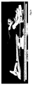
- Figure 1a shows a three-dimensional depiction of the device.
- Figure 1b shows the same device with moving axes for an ergonomic position of the patient.
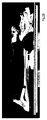
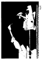
- Figures 2 to 3 are three-dimensional depictions of preferred embodiments of the modules and/or devices.
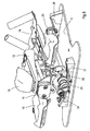
- Figures 4 a and b show a self-locking mechanism for the rotational movement.
- Figure 5 discloses a three-dimensional view of a preferred thoracic module, showing a preferred embodiment of the rotation system.
- Figures 6 to 9 are cross-sectional depictions of a preferred synchronised pivoting system.
- Figure 10 discloses a three-dimensional view of a preferred caudal module, showing a preferred embodiment of the rotation system.
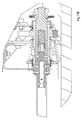
- Figures 11 a and b are cross-sectional depictions of a preferred connection of the synchronisation axis with the co-rotating and quick release mechanism, whereby Figure 11 a shows the self-locked position, and Figure 11b the locked and co-corotational position.
- Figure 12 is a three-dimensional depictation of a preferred device comprising a cephalic, and a combined thoracic and a caudal module, whereby the modules are connected by the corotation synchronisation axis.
- Table 1 List of terms and reference numbers Reference Number Term 1 Device 2 cephalic module 3 thoracic module 4 caudal module 5 head rest 6 Hand rest 7 base 8 primary pivoting drive/lock 9 synchronisation axis/shaft 10 secondary pivoting drive/lock 11 elbow rest 12 Quick disconnect system 13 alignment bar 14 Gear 15 toothed lever 16 treatment table 17 curved rack 18 hinged lever 19 spring loaded operator grip 20 Cam 21 Slit 22 locking element 23 locking element 24 locking element 25 Base Plate 26 Chin support 27 Forehead support Table 2: list of moving axes for comfortable position of the patient Moving axes for ergonomic assemblies Ergonomic assembly Device Axe of moving the device Axe of Interconnection All the modules All F F Arms support Hands support A E Elbow support B Arms support E Head support Chin Fixed A Forehead A/C Table 3 Reference Number Term 1 Device 2 Cephalic module 3 Thoracic module 4 Caudal module 5 Cephalic inclinable support 6 Cephalic mechanism support 7 Caudal mechanism support 8 Caudal inclinable support 9 Operator grip 10 Co-
- the device according to the invention is preferably adaptable to be reproducibly secured to a treatment table.
- the patient immobilisation device preferably comprises different interconnected modules arranged to rotate around a longitudinal axe or the craniocaudal patient axis F.
- the device is also arranged to provide a comfortable and an ergonomic position for the patient during treatment.
- the modules are secured adaptably and indexed to each other to fit the patient anatomy.
- the device is advantageously indexed pivotably around the craniocaudal patient axis F.
- the device preferably further comprises a co-rotation system for controlling of the pivoting motion of at least the cephalic and thoracic module.
- the patient once placed on the device, can advantageously be inclined in an angle by means of a subsystem that acts on the whole of the patient immobilisation device. Applicants found that this leads to further distancing of the treated breast from the rest of the body, which was in particular found useful for patients with pendulous breasts.
- the element bridging this area preferably has a reduced, cut-out section. As a consequence this element and its mechanical interface to the adjacent structure may be deformed under load during the inclination movement.
- the device advantageously comprises a synchronization system that controls the inclination of the patient immobilisation device when it is moved, as well as keeping the whole system stable and well aligned in static position.
- the synchronization axis also allows to link the cephalic and the caudal module in a proper aligned way.
- This concept is referred herein to as the "co-rotation system”, and preferably comprises a number of elements.
- the co-rotation system preferably comprises a) at least a primary lock and at least a secondary lock, and b) at least a synchronizing element that controls and coordinates the movement of the primary and the secondary lock.
- the primary lock preferably has a human interface allowing an operator to change the inclination of the patient manually.
- the secondary lock is preferably moved by the movement of the primary lock through the synchronizing element, advantageously in the form of a synchronising axis.
- the craniocaudal patient axis F may advantageously run through the patient directly, or, in an embodiment not covered by the invention, may be preferably off-set to a parallel position below the patient.
- the latter preferably permits to place the pivoting mechanism below the patient and to be disconnected and removed at rest in a-position that conveniently does not interfere with the radiation or scanning equipment. In either case, the device permits to place the patient at a position at an angle with respect to the prone position around the actual craniocaudal patient axis F.
- the device further preferably comprises a mechanical support structure guiding the pivoting movement of at least the cephalic and thoracic module.
- the primary lock preferably may have a human interface allowing an operator to change the inclination of the patient manually
- the secondary locks preferably cannot be controlled directly by the operator.
- the locking system preferably holds the neutral (0°) and inclined positions in a safe and mechanically secured way.
- the synchronizing axis may be removed to enhance imaging/treatment performance. When the synchronizing axis has been removed the locks are engaged and cannot be released hence in order to move the system the synchronizing axis must be in place.
- the device preferably has a capacity to angle the entire board from -10° to +10°, more preferably from 0 to -6°.
- the pivoting action is preferably indexed in increments of 1°.
- the angling or pivoting system will preferably be completely incorporated in the system to avoid unnecessary supplementary mechanical tools and reduce the weight.
- the device further comprise a head rest (5), a hand rest (6), an elbow rest (11) supports that are arranged to move independently from each other along their respective axe (A to E).
- the hand rest support (6) is arranged to move along axe A ; the elbow rest support (11), along axe (B) . Both are connected on a base plate also called arm support (25) which move along axe E.
- the headrest support comprises an ergonomic forehead support (27) and an ergonomic chin support (26).
- the chin support and the forehead support are arranged to move each independently along axes A and C and to rotate around axe D.
- the hand rest support (6) and elbow rest support (11) are sliding supports attached on a sliding arm support and the arm support (25) can move along axe E.
- FIG. 2a and Fig 2b represent an example of embodiment according to the invention wherein the immobilisation device comprises three interconnected modules.
- Both cephalic and caudal modules are interconnected through the synchronization axis and the thoracic module in Fig 2a .
- a rotation of the patient may be engaged to further enhance the treatment positioning.
- the synchronization axis may further be disconnected as represented in Fig 2b to allow breast treatment.
- Fig 2c shows an assembly of the immobilization device, particularly how the thoracic module is interconnected with the cephalic module and the caudal module.
- Fig 2d shows the connection of the caudal module to the cephalic module with a synchronization axis.
- the synchronization axis transfers the rotational forces from the caudal rotating module to the cephalic rotating module.
- the synchronisation axis can be easily disconnected thanks to a rapid connection system.
- the synchronizing axis can then be pulled back but all cephalic, thoracic and caudal modules remain locked.
- the combined immobilization device remains locked in such position. No rotation is possible at this stage.
- an operator cannot engage a rotational movement to the device as long as the synchronization axis that generates rotation, is not engaged.
- Figure 3 shows an example of cephalic module including head rest support, hand rest support, elbows rest support positioned on a sliding arm support.
- Figure 4 a and b show a particularly preferred embodiment of a self-locking rotation lock.
- Figure 4 a shows the unlocked position upon insertion of the synchronisation axis
- Figure 4 b shows the locked position, upon removal of the synchronisation axis.
- Figure 5 discloses a three-dimensional view of a preferred thoracic module, showing a preferred embodiment of the rotation system.
- Two alignment bars (13) are present (at the cephalic and thoracic portion levels) to ensure identical positioning from day to day.
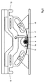
- Figure 6 depicts a preferred embodiment of the device of the present invention for use with a patient in the prone position, specifically the primary lock/drive of the synchronised pivoting element.
- the synchronization axis (9) transfers a rotation between different supporting modules of the patient immobilisation device.
- the synchronization axis (9) can slide along its centre axis and has coinciding engaging positions with both primary (8) and secondary locks (10).
- To release the primary lock the operator moves the grip (19).
- When holding the grip the operator can change the inclination angle of the patient immobilisation device two-ways (CW or CCW) by pushing/pulling.
- the curved rack (17) is attached to the treatment table (16).
- Figure 7 depicts a preferred embodiment of the device of the present invention for use with a patient in the prone position, namely the side-on view of the secondary lock/drive linked to the first drive by synchronization axis (9).
- a toothed lever (15) and a curved rack (17) are linked to synchronization axis (9).
- the curved rack (17) is attached to the treatment table (16).
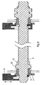
- Figure 8 shows a cross-sectional view of an embodiment of the interconnection between the primary lock.
- the tube section of the synchronizing axis blocks the toothed lever (15) down which locking the co-rotation mechanism.
- the operator activates a spring-loaded grip (19) that moves a hinged lever (18) that then lifts a toothed lever (15) which hereby is disengaged from a curved rack (17).
- the curved rack is part of the structural support of the patient immobilisation device and is located on a patient positioning table top (16) or similar equipment.
- a gear (14) transmits the rotation generated by the displacement to the synchronizing axis (9). As follows: as long as the operator holds the grip the inclination position can be changed. Once released hinged lever (18) forces toothed lever (15) back into its locking position onto the curved rack (17).
- the racks tooth geometry corresponds to a defined step in the inclination, for example 1 degree per tooth position. With the lock freed, i.e.
- the synchronization axis (9) cannot be removed because a locking element (22) inserted into a slot (23) of the synchronization axis prevents the axis's sliding movement. Consequently when the lock is engaged, i.e grip (19) released, the geometry of the locking element (22) clears the slot of the synchronization axis allowing the operator to slide the axis and at the same time it prevents to disengage the lock.
- the synchronization axis when in retracted position, remains in the primary lock, the geometry (diameter) preventing the lock to disengage by blocking element locking element (22).
- Figure 9 depicts how the secondary lock not having the human interface is controlled by means of the synchronization axis (9) position within the lock.
- the toothed lever (15) is pushing down by a spring and the co-rotation mechanism is locked.
- the shape of the shaft tip pushes the toothed lever up witch unlock the co-rotation mechanism in coordination with the primary lock.
- the co-rotation motion is done by the keys (cams) (20) fixed on the shaft(9) going into the slits of the pinion tube (21).
- Figure 9 depicts how the secondary lock not having the human interface is controlled by means of the synchronization axis (9) position within the lock.
- a gear (14) and curved rack (17) can freely move and thus the inclination position can be modified by the manipulation of the operator of the primary lock, wherein rotational movement is transmitted by means of synchronization axis (9).
- the synchronization axis interfaces with an element (23) that is directly mounted to toothed lever (15). This element itself has a part (24) hard-mounted on it, the synchronization axis (9) geometry positioning the toothed lever, thereby clearing it from the curved rack (17).
- the synchronization axis preferably has a number of cams (20) on along its periphery. Each set of cams is positioned on the axis corresponding to the locations of the different primary and secondary locks. The cam sets are aligned ensuring that all locks are engaged at the same time and at the same angle. When the operator moves the synchronization axis in its stored position both primary and secondary locks are disengaged in parallel and as a result all the patient immobilisation device's modules are blocked into the same inclined position. When the operator re-inserts the synchronization axis and the cams interface in slots (21) on the different gears, also these slots remain aligned geometrical disposition as described above ensures there is no geometrical conflict.
- Fig. 10 depicts a further preferred embodiment of the rotation system on the caudal module.
- the shaft section tube blocks the toothed pinion lever (21) down which locks the co-rotation system.
- the co-rotation shaft (10) is engaged , there is a recess in the shaft section tube located at the toothed pinion lever (21) that allows the lever (21) to be activated up by the triggers (20) .
- the toothed pinion lever (21) release the toothed pinion lock (22) and the operator can incline the system using the hand grips (9).
- the co-rotation motion is done by the keys (cams) (36) fixed on the shaft(10) going into the slots of the pinion tube (35).
- the toothed pinion lever is automatically locked down blocking the inclination position and the co-rotation mechanism.
- the section of the shaft tube automatically blocks the toothed pinion lever down, which deactivates the triggers (20) automatically. An operator can now no longer incline the table. Inclination position and co-rotation mechanism are locked.
- the corotation shaft (10) is operably locked by a removable quick-release a ball mechanism which allows the following operations:
- the shaft When in corotation mode, the shaft is locked along its axis so that it cannot be removed, but is held firmly in place by a set of balls (37) moving in a sliding sleeve (29).
- the sliding sleeve is in forward position, so that in this position, the pinion lock is open.
- the corotation shaft moves the pinion (30) through keys installed on the shaft.
- the ball spigot (32) locks the balls (37) in their position, thus preventing any movement of the sliding sleeve (29) and consequently securing the pinion lock 28).
- Co-rotation system lock release There are reservations in the sliding locking piston (30) containing the locking balls (34). When the corotation shaft is removed , the sliding locking piston (30) is in the rear position. It cannot go further back because of the Stop circlip (37); and it cannot go forward because the Balls locking piston (33) maintains the locking balls (34) in the reservation of the Pinion tube (35). In this position, the sliding locking piston tip (31) maintains the front toothed pinion lock lever(29) down. This lever (29) controls the front thoothed pinion locking(26) and so , the system is locked.
- the balls are going into the grove of the shaft head and so the sliding locking piston (30) can slide forward , pushed by the corotation shaft head through the balls.
- the co-rotation motion is done by the Corotation keys (36) going into the slots of the Pinion tube (38)
- Co-rotation system locking When removed, the shaft pulls the sliding locking piston (30) back through the balls (34) until the balls are pushed out into the reservation of the Pinion tube (35) where the balls are maintain by the balls locking piston (33).
- the assembled preferred device comprising cephalic, thoracic and caudal module and the preferred locking and synchronization mechanism is depicted in Figure 12 .
- the portions of the modules that are adjacent to the irradiation source during treatment are preferably essentially radiolucent.
- the essentially radiolucent material may comprise a composite material, preferably carbon composite material. It more preferably does not comprise metallic parts in the portions of the modules that are adjacent to the irradiation source during treatment.
- the walls of at least the thoracic portion are preferably perforated to produce an open area.
- the modules are preferably collapsible, to allow the device to be stowed away and/or transported in a collapsed way.
- the cephalic module, the thoracic module and the caudal module are adjustably connected by means that are suitable to fasten the three modules to each other.
- the connection is such that each module has a means for fastening the next module which is formed to receive a securing means for connecting the module to the next module.
- the thoracic module preferably comprises holes, preferably symmetrical holes aligned on the side supporting the untreated breast.
- the triangular portion at the sternal interface is preferably adapted to the patient sternum anatomy. It is preferably padded with foam, which permits to decrease distortion of a CT planning beam.
- the patient immobilization device of the present invention can preferably be attached to most standard patient tables or couches by various attachment means.
- the securing means can be a removable device or it is preferably integrated into the base structure with appropriately means, such as holes and pins, so that it universally fits most common patient tables.
- the patient immobilization device of the present invention is adjustable in several ways. First, the device can be adjusted to fit most commercially available treatment tables. This adjustability provides complete flexibility in that the device of the present invention is self-contained and fits most existing procedure tables. There is no need for retrofitting or additional clamping or securing means.
- the patient immobilization device of the present invention adjusts on two sides and can easily be centred on a procedure table because of its two-way adjustability.
- the device preferably is rapidly and easily assembled to form a rigid frame. The assembled device is then preferably clamped onto the scan or treatment table through standard perforations available on all commercial systems.
- two alignment bars are present, more preferably at the cephalic and thoracic module to ensure identical positioning in subsequent treatment.
- the system is preferably essentially composed from carbon fibre composites and thermosetting plastics, especially in the treatment area.
- the synchronising axis is removable once a selected inclination is set for the thoracic and the cephalic module.
- the synchronisation axis if statically retained between the two modules, may lead to artefacts in both the image acquisition of a patient, as well as in the treatment, the latter potentially resulting in an increased risk for collateral damage due to undesired radiation exposure.
- the synchronisation element or axis is reversibly removable to reduce the artefact formation during patient imaging and/or treatment.
- the co-rotation system further comprises a self-locking mechanism that immobilizes the co-rotation movement of the synchronised modules upon removal of the synchronisation element.
- the rotationally immobilized modules are detachable after removal of the synchronisation element, to permit reproducibility of the patient position.
- the present invention therefore also relates to a particularly preferred embodiment, wherein the synchronisation axis is removable after the inclination angle has been set to a certain value, and wherein the rotation mechanisms are locked automatically by the removal of the axis. Even more preferably, the actual removal of the axis should self-lock the rotational mechanism one or both modules, avoiding any deviation from the synchronised and set angle due to operator or patient moves.
- a particularly preferred embodiment of the subject invention comprises a self-locking and quick release system in the co-rotation mechanism, which permits the operator to easily set the desired and identical angle for the synchronised modules, and subsequently allows removing the synchronisation axis, and to separate the modules, since the removal of the axis self-locks the co-rotational system, and hence fixes the inclination angle.
- the present device preferably comprises a combined self-locking and fast release system, which when operably engaged, co-rotates the rotation mechanism of the two modules, while upon release self-locks these mechanisms such that there is no movement feasible, and allows the removal of the axis by an operator.
- Figures 4 a and 4 b as well as Figures 11 a and 11b show the operation of a particularly preferred embodiment of this system, which is characterised as follows: if the synchronsation axis is inserted, the system is unlocked for co-rotation.
- the sliding locking piston (30) When the corotation synchronisation axis is removed, the sliding locking piston (30) is in the rear position. It cannot move further back because of the stop circlip (37); and it cannot move forward because at the same time, since the ball locking piston (33) maintains the locking balls (34) in the indentation of the Pinion tube (35). In this position, the sliding locking piston tip (31) maintains the front toothed pinion lock lever (29) down and engaged with front thoothed pinion locking (26), thereby effectively locking the rotational system and prohibiting any pivotal rotational action.
- the balls are going into the grove of the shaft head and so the sliding locking piston (30) can slide forward , pushed by the the synchronisation axis shaft head through the balls.
- the shape of the sliding piston tip (31) allows to release the front toothed pinion lock lever.
- This lever may pulled up by a spring and thus activate the front toothed pinion lock (26) to the upper position, which thereby unlocks the rotational mechanism.
- the co-rotation motion is transmitted from the rotation of the synchronisation axis by the corotation keys (36) that are inserted at the same time into fitting slots on the pinion tube (38).
- Performance of the device is directly influenced by the material used for its construction. Lighter elements are preferred over heavier elements. For example, the lighter elements in composites and polymer materials result in less elastic and inelastic radiation scattering compared to materials containing metals or alloys.
- fluorescence is reduced. For example, when a metal atom is impacted by radiation, it absorbs the radiation energy by ejecting an electron from its shell in the atom's electron cloud. When an electron falls back into the shell, radiation is emitted. This effect is known as fluorescence. Because the radiation can be emitted in any direction, the patient can be subjected to an undirected dose of radiation energy.
- Metals are also undesirable due to their high radiation absorption compared to plastics and carbon composite. Because of the high radiation absorption, the use of metals in the device can also reduce the therapy dose available to the patient.
- All components of the present invention can be non-metallic although some metallic parts can be used if they do not disrupt the performance of the device.
- the individual components may be selected based on the intended use of the device, but advantageously are crafted from materials that are essentially radiolucent, such as carbon fibre epoxy resin composite. This particular feature is especially important if a highly oblique angle must be used for treating the patient where the device could come into the line of the high-energy beam.
- a radiolucent device allows imaging and treatment of a patient through the patient immobilization device. This increases the treatment flexibility by allowing an accurate attack of the cancer or tumour from all aspects and angles.
- the present invention can be used in conjunction with most available tables as well as most available accessories that can be used with the patient immobilization device.
Landscapes
- Health & Medical Sciences (AREA)
- Life Sciences & Earth Sciences (AREA)
- Engineering & Computer Science (AREA)
- Biomedical Technology (AREA)
- Medical Informatics (AREA)
- Veterinary Medicine (AREA)
- Pathology (AREA)
- Animal Behavior & Ethology (AREA)
- General Health & Medical Sciences (AREA)
- Public Health (AREA)
- Radiology & Medical Imaging (AREA)
- Nuclear Medicine, Radiotherapy & Molecular Imaging (AREA)
- Physics & Mathematics (AREA)
- Biophysics (AREA)
- Heart & Thoracic Surgery (AREA)
- Molecular Biology (AREA)
- Surgery (AREA)
- High Energy & Nuclear Physics (AREA)
- Optics & Photonics (AREA)
- Radiation-Therapy Devices (AREA)
- Accommodation For Nursing Or Treatment Tables (AREA)
Claims (20)
- Patienteinruhigstellungsvorrichtung (1) zur Positionierung einer/eines Patientin/Patienten in Bauchlage zur Bestrahlung der Brust, umfassend
ein Schädelmodul (2) zum Stützen des Kopfs und der oberen Extremitäten der/des Patientin/Patienten,
ein Thoraxmodul (3) zum Stützen des Thorax der/des Patientin/Patienten, das so gestaltet ist, dass sich mindestens eine Brust unter das Thoraxmodul erstrecken kann, und
ein Kaudalmodul (4) zum Stützen des Beckens und der unteren Extremitäten der/des Patientin/Patienten,
wobei das Schädelmodul abnehmbar ist und am Thoraxmodul befestigt werden kann und
wobei das Thoraxmodul abnehmbar ist und am Kaudalmodul befestigt werden kann,
dadurch gekennzeichnet, dass die Vorrichtung taktmäßig um eine kraniokaudale Patientenachse F, die vom Kopf der/des Patientin/Patienten bis zu den Beinen durch diese/diesen verläuft, geschwenkt werden kann. - Vorrichtung nach Anspruch 1, wobei die Vorrichtung geeignet ist, reproduzierbar an einem Behandlungstisch (16) befestigt zu werden.
- Vorrichtung nach Anspruch 1, zur Bereitstellung einer bequemen und ergonomischen Position für die/den Patientin/Patienten während der Behandlung, wobei die Module in Übereinstimmung mit der Patientenanatomie anpassbar und taktmäßig aneinander befestigt sind.
- Vorrichtung nach einem der Ansprüche 1 - 3, ferner umfassend ein Co-Rotationssystem zur Steuerung der Schwenkbewegung mindestens des Schädel- und des Thoraxmoduls.
- Vorrichtung nach Anspruch 4, wobei das Co-Rotationssystem Folgendes umfasst:a) mindestens eine Primärverriegelung (8) und mindestens eine Sekundärverriegelung (10) undb) mindestens eine Synchronisierachse (9), die die Bewegung der Primärund der Sekundärverriegelung steuert und koordiniert.
- Vorrichtung nach einem der Ansprüche 1 - 5, ferner umfassend eine mechanische Stützstruktur, die die Position mindestens des Schädel- und des Thoraxmoduls führt.
- Vorrichtung nach einem der Ansprüche 5 bis 6, wobei die Primärverriegelung ein Human Interface hat, mit dessen Hilfe eine Bedienperson die Neigung der/des Patientin/Patienten manuell ändern kann.
- Vorrichtung nach einem der Ansprüche 5 bis 6, wobei die Sekundärverriegelung (10) durch die Bewegung der Primärverriegelung (8) durch die Synchronisierachse (9) bewegt wird.
- Vorrichtung nach einem der Ansprüche 5 bis 8, wobei das Kaudalmodul und das Schädelmodul vor dem Verriegeln und Co-Rotieren der Primärund der Sekundärverriegelung mit dem Synchronisierelement (9) getrennt verstellt und durch die Bewegung der Primärverriegelung (8) bewegt werden können.
- Vorrichtung nach einem der Ansprüche 1 bis 9, wobei die Vorrichtung in einem Winkel von -10° bis +10° taktmäßig um die kraniokaudale Patientenachse F geschwenkt werden kann.
- Vorrichtung nach einem der vorhergehenden Ansprüche, wobei Abschnitte der Module, die während der Behandlung einer Bestrahlungsquelle benachbart sind, im Wesentlichen strahlendurchlässig sind.
- Vorrichtung nach einem der vorhergehenden Ansprüche, wobei die Module zusammenklappbar sind, damit die Vorrichtung zusammengeklappt verstaut und/oder transportiert werden kann.
- Vorrichtung nach einem der vorhergehenden Ansprüche, wobei Wände mindestens des Thoraxmoduls perforiert sind, um einen offenen Bereich herzustellen.
- Vorrichtung nach Anspruch 5, wobei die Synchronisierachse reversibel entfernbar ist, um Artefaktbildung während der Abbildung und/oder Behandlung der/des Patientin/Patienten zu reduzieren.
- Vorrichtung nach Anspruch 14, wobei das Co-Rotationssystem ferner einen Selbsiverriegelungsmechanismus umfasst, der bei Entfernung des Synchronisierelements eine Co-Rotationsbewegung von synchronisierten Modulen immobilisiert.
- Vorrichtung nach Anspruch 15, wobei die Module nach drehungsmäßiger Immobilisierung nach der Entfernung der Synchronisierachse entfernbar sind, ohne die Einstellungen des Co-Rotationsmechanismus zu beeinflussen, um eine Ausrichtung nicht zu stören, wenn die Module wieder zusammengebaut werden, um die Wiederholbarkeit der Patientenposition zu gestatten.
- Vorrichtung nach Anspruch 16, umfassend:einen gleitenden Verriegelungskolben (30), Verriegelungskugeln (34), einen Anschlagsicherungsring (37), einen Kugelverriegelungskolben (33) und eine Ritzelröhre (35), wobei der gleitende Verriegelungskolben (30) und die Verriegelungskugeln (34) betriebsmäßig so platziert sind, dass der gleitende Verriegelungskolben (30), wenn die Synchronisierachse nach der Co-Rotation entfernt wird, durch einen Anschlagsicherungsring (37) unbeweglich in einer hinteren Position gehalten wird und ein Kugelverriegelungskolben (33) die Verriegelungskugeln (34) in der Vertiefung einer Ritzelröhre (35) hält, wobei die Spitze (31) des gleitenden Verriegelungskolbens den vorderen gezahnten Ritzelverriegclungshebel (29) in einer unteren Position und im Eingriff mit der vorderen gezahnten Ritzelverriegelung (26) hält, wodurch das Drehsystem wirksam verriegelt und jede Schwenkdrehung verhindert wird.
- Vorrichtung nach Anspruch 17, ferner umfassend eine Feder (32), wobei der Wellenkopf, wenn er die Co-Rotationswelle (10) der Synchronisierachse in den gleitenden Verriegelungskolben (30) in Eingriff bringt, die Feder (32) zusammendrückt und den Kugelverriegelungskolben (33), der die Kugeln (34) entriegelt, verschiebt, so dass die Kugeln (34) in eine Nut des Wellenkopfs gehen, so dass der gleitende Verriegelungskolben (30), durch den Co-Rotationswellenkopf durch die Kugeln geschoben, vorwärtsgleiten kann, wodurch der vordere gezahnte Ritzelverriegelungshebel in eine obere Position freigegeben und somit der Drehmechanismus entriegelt wird, während gestattet wird, dass eine Co-Rotationsbewegung von der Drehung der Synchronisierachse übertragen wird, indem die Co-Rotationskeile (36) in passende Schlitze an der Ritzelröhre (38) eingeführt werden.
- Verfahren zum Scannen einer/eines Patientin/Patienten, umfassend Bereitstellen eines Schädelmoduls zum Stützen des Kopfs und der oberen Extremitäten der/des Patientin/Patienten, eines Thoraxmoduls zum Stützen des Thorax der/des Patientin/Patienten, das so gestaltet ist, dass sich mindestens eine Brust unter das Thoraxmodul erstrecken kann, und eines Kaudalmoduls zum Stützen des Beckens und der unteren Extremitäten der/des Patientin/Patienten, wobei die Vorrichtung taktmäßig um eine kraniokaudale Patientenachse F, die vom Kopf der/des Patientin/Patienten bis zu den Beinen durch diese/diesen verläuft, geschwenkt werden kann, und
wobei das Schädelmodul wahlweise abnehmbar ist und am Thoraxmodul befestigt werden kann und wobei das Thoraxmodul wahlweise abnehmbar ist und am Kaudalmodul befestigt werden kann, und Aussetzen mindestens eines Abschnitts der sich unter das Thoraxmodul erstreckenden Brust einer ionisierenden Strahlung für eine geeignete Zeitdauer und eine geeignete Strahlungsrate. - Verwendung der Vorrichtung nach einem der Ansprüche 1 bis 18 zum Scannen einer/eines Patientin/Patienten.
Priority Applications (1)
| Application Number | Priority Date | Filing Date | Title |
|---|---|---|---|
| EP13709458.7A EP2827950B1 (de) | 2012-03-19 | 2013-03-15 | Patientenliegenvorrichtung zur ruhigstellung in bauchlage |
Applications Claiming Priority (4)
| Application Number | Priority Date | Filing Date | Title |
|---|---|---|---|
| EP12160081.1A EP2641634A1 (de) | 2012-03-19 | 2012-03-19 | Patientenliegenvorrichtung zur Ruhigstellung in Bauchlage |
| EP12189876 | 2012-10-25 | ||
| PCT/EP2013/055492 WO2013139713A1 (en) | 2012-03-19 | 2013-03-15 | Patient support device for prone immobilization. |
| EP13709458.7A EP2827950B1 (de) | 2012-03-19 | 2013-03-15 | Patientenliegenvorrichtung zur ruhigstellung in bauchlage |
Publications (2)
| Publication Number | Publication Date |
|---|---|
| EP2827950A1 EP2827950A1 (de) | 2015-01-28 |
| EP2827950B1 true EP2827950B1 (de) | 2016-11-16 |
Family
ID=47884359
Family Applications (1)
| Application Number | Title | Priority Date | Filing Date |
|---|---|---|---|
| EP13709458.7A Not-in-force EP2827950B1 (de) | 2012-03-19 | 2013-03-15 | Patientenliegenvorrichtung zur ruhigstellung in bauchlage |
Country Status (6)
| Country | Link |
|---|---|
| US (1) | US9615796B2 (de) |
| EP (1) | EP2827950B1 (de) |
| CN (1) | CN104363958B (de) |
| CA (1) | CA2866221C (de) |
| RU (1) | RU2630772C2 (de) |
| WO (1) | WO2013139713A1 (de) |
Families Citing this family (10)
| Publication number | Priority date | Publication date | Assignee | Title |
|---|---|---|---|---|
| CN103565464B (zh) * | 2013-10-10 | 2015-07-08 | 房克霞 | 乳腺ect检测辅助器 |
| CA2943362C (en) * | 2014-03-24 | 2023-10-03 | Universiteit Gent | Radiotherapy board and couch |
| US9990333B1 (en) * | 2014-05-28 | 2018-06-05 | University Of South Florida | Systems and methods for synchronizing the kinematics of uncoupled, dissimilar rotational systems |
| JP6611428B2 (ja) * | 2014-12-09 | 2019-11-27 | キヤノン株式会社 | マンモ断層撮像システム |
| CN109199762B (zh) * | 2018-11-13 | 2023-09-22 | 上海长海医院 | 一种烧伤后四肢换药肢体支撑装置 |
| EP3698720A1 (de) * | 2019-02-19 | 2020-08-26 | Herlev Hospital | Kopf- und armlehnenvorrichtung zur verwendung in der medizinischen abtastung |
| CN109793635A (zh) * | 2019-03-04 | 2019-05-24 | 上海交通大学医学院附属第九人民医院 | 用于颈椎手术的术前辅助翻身及术中固定装置 |
| EP4076200B1 (de) | 2019-12-17 | 2025-05-21 | Medtec, Inc. | Patientenbildgebungs- und behandlungstischverlängerung mit integrierten handläufen |
| CN112156380B (zh) * | 2020-10-26 | 2022-09-23 | 广州医科大学附属肿瘤医院 | 一种体部精准放疗固定装置 |
| CN115153479B (zh) * | 2022-09-05 | 2024-02-06 | 杭州中芯微电子有限公司 | 一种适用于医疗机构患者腕部的智能腕带 |
Family Cites Families (10)
| Publication number | Priority date | Publication date | Assignee | Title |
|---|---|---|---|---|
| SU103853A2 (ru) * | 1952-05-12 | 1955-11-30 | И.В. Дрозов | Стол дл рентгенологических и других медицинских целей |
| US5208928A (en) * | 1991-09-20 | 1993-05-11 | Midmark Corporation | Plastic surgery table |
| US6698045B1 (en) * | 2001-11-02 | 2004-03-02 | Anholt Technologies, Inc. | Angling head immobilization device |
| US7127281B2 (en) * | 2002-03-01 | 2006-10-24 | Wisconsin Alumni Research Foundation | Patient support and method for studies of lumbar vertebra rotation |
| US7763864B2 (en) * | 2005-04-06 | 2010-07-27 | New York University | Radiation treatment table and method for prone breast radiation treatment |
| US7640607B2 (en) * | 2005-04-29 | 2010-01-05 | Varian Medical Systems, Inc. | Patient support systems |
| CN101715309B (zh) * | 2005-09-24 | 2013-06-12 | Qfix系统有限责任公司 | 与诊断成像兼容的放射治疗病床床面 |
| WO2009033035A1 (en) * | 2007-09-06 | 2009-03-12 | Orbital Therapy Llc | A patient support system for full access prone position breast radiotherapy |
| US8295430B2 (en) * | 2009-06-29 | 2012-10-23 | Imris Inc. | Image guided radiation therapy |
| US8374312B2 (en) * | 2010-02-18 | 2013-02-12 | Varian Medical Systems, Inc. | Prone patient positioning devices and methods |
-
2013
- 2013-03-15 EP EP13709458.7A patent/EP2827950B1/de not_active Not-in-force
- 2013-03-15 CA CA2866221A patent/CA2866221C/en active Active
- 2013-03-15 RU RU2014141343A patent/RU2630772C2/ru not_active IP Right Cessation
- 2013-03-15 US US14/386,194 patent/US9615796B2/en not_active Expired - Fee Related
- 2013-03-15 WO PCT/EP2013/055492 patent/WO2013139713A1/en not_active Ceased
- 2013-03-15 CN CN201380015478.5A patent/CN104363958B/zh not_active Expired - Fee Related
Non-Patent Citations (1)
| Title |
|---|
| None * |
Also Published As
| Publication number | Publication date |
|---|---|
| WO2013139713A1 (en) | 2013-09-26 |
| RU2630772C2 (ru) | 2017-09-12 |
| US20150034091A1 (en) | 2015-02-05 |
| CN104363958B (zh) | 2017-08-08 |
| RU2014141343A (ru) | 2016-05-10 |
| US9615796B2 (en) | 2017-04-11 |
| EP2827950A1 (de) | 2015-01-28 |
| CN104363958A (zh) | 2015-02-18 |
| CA2866221C (en) | 2020-07-14 |
| CA2866221A1 (en) | 2013-09-26 |
Similar Documents
| Publication | Publication Date | Title |
|---|---|---|
| EP2827950B1 (de) | Patientenliegenvorrichtung zur ruhigstellung in bauchlage | |
| US6698045B1 (en) | Angling head immobilization device | |
| JP2008504089A (ja) | 患者の位置決め装置 | |
| KR101081839B1 (ko) | 모듈러 환자 서포트 시스템 | |
| US5168514A (en) | Modular radiotherapy treatment chair and methods of treatment | |
| US8443473B2 (en) | Patient positioning frame device and application technique | |
| EP1567110B1 (de) | Patientenstützvorrichtung mit schulter-depressions-vorrichtung | |
| US7676255B2 (en) | System and method for supporting a patient during medical imaging | |
| US11684532B2 (en) | Method and apparatus for supporting and stabilizing a patient during hip distraction | |
| US6722783B2 (en) | X-ray chair | |
| CN101641748A (zh) | 用于固定乳腺放疗患者的装置和方法 | |
| EP1174087A2 (de) | Tischplatte für Radiotherapie und Diagnostikbildaufnahme | |
| US11607357B2 (en) | Positioning device for beam radiation treatment and imaging | |
| EP3581240B1 (de) | Immobilisierungsvorrichtung für die strahlentherapie | |
| EP1894528B1 (de) | Rollstuhl | |
| US8371305B1 (en) | Fluoroscopy chair with radiolucent, adjustable supports convertible to resuscitation table | |
| WO2018120604A1 (zh) | 一种用于粒子放疗的坐姿固定装置 | |
| US8397731B1 (en) | Adjustable, radio-translucent chest, neck, and head support arm attachment for C-arm tables for radioscopy-guided procedures | |
| JP7604581B2 (ja) | 患者位置決め用システム及び方法 | |
| CN112245813A (zh) | 一种可移动式妇科肿瘤放疗平台设备 | |
| EP2641634A1 (de) | Patientenliegenvorrichtung zur Ruhigstellung in Bauchlage | |
| CN210992672U (zh) | 一种人体固定支撑装置 | |
| LU602698B1 (en) | Thoracoabdominal tumor radiotherapy positioning and fixation device | |
| CN222640692U (zh) | 一种躺坐牵引式脊柱矫形装置 | |
| CN110522589A (zh) | 一种内分泌科治疗床 |
Legal Events
| Date | Code | Title | Description |
|---|---|---|---|
| PUAI | Public reference made under article 153(3) epc to a published international application that has entered the european phase |
Free format text: ORIGINAL CODE: 0009012 |
|
| 17P | Request for examination filed |
Effective date: 20141020 |
|
| AK | Designated contracting states |
Kind code of ref document: A1 Designated state(s): AL AT BE BG CH CY CZ DE DK EE ES FI FR GB GR HR HU IE IS IT LI LT LU LV MC MK MT NL NO PL PT RO RS SE SI SK SM TR |
|
| AX | Request for extension of the european patent |
Extension state: BA ME |
|
| DAX | Request for extension of the european patent (deleted) | ||
| 17Q | First examination report despatched |
Effective date: 20160118 |
|
| GRAP | Despatch of communication of intention to grant a patent |
Free format text: ORIGINAL CODE: EPIDOSNIGR1 |
|
| INTG | Intention to grant announced |
Effective date: 20160826 |
|
| GRAS | Grant fee paid |
Free format text: ORIGINAL CODE: EPIDOSNIGR3 |
|
| GRAA | (expected) grant |
Free format text: ORIGINAL CODE: 0009210 |
|
| AK | Designated contracting states |
Kind code of ref document: B1 Designated state(s): AL AT BE BG CH CY CZ DE DK EE ES FI FR GB GR HR HU IE IS IT LI LT LU LV MC MK MT NL NO PL PT RO RS SE SI SK SM TR |
|
| REG | Reference to a national code |
Ref country code: GB Ref legal event code: FG4D |
|
| REG | Reference to a national code |
Ref country code: CH Ref legal event code: EP |
|
| REG | Reference to a national code |
Ref country code: IE Ref legal event code: FG4D |
|
| REG | Reference to a national code |
Ref country code: AT Ref legal event code: REF Ref document number: 845356 Country of ref document: AT Kind code of ref document: T Effective date: 20161215 |
|
| REG | Reference to a national code |
Ref country code: DE Ref legal event code: R096 Ref document number: 602013014080 Country of ref document: DE |
|
| REG | Reference to a national code |
Ref country code: DE Ref legal event code: R096 Ref document number: 602013014080 Country of ref document: DE |
|
| REG | Reference to a national code |
Ref country code: NL Ref legal event code: FP |
|
| PG25 | Lapsed in a contracting state [announced via postgrant information from national office to epo] |
Ref country code: LV Free format text: LAPSE BECAUSE OF FAILURE TO SUBMIT A TRANSLATION OF THE DESCRIPTION OR TO PAY THE FEE WITHIN THE PRESCRIBED TIME-LIMIT Effective date: 20161116 |
|
| REG | Reference to a national code |
Ref country code: FR Ref legal event code: PLFP Year of fee payment: 5 |
|
| REG | Reference to a national code |
Ref country code: LT Ref legal event code: MG4D |
|
| REG | Reference to a national code |
Ref country code: NO Ref legal event code: T2 Effective date: 20161116 |
|
| REG | Reference to a national code |
Ref country code: AT Ref legal event code: MK05 Ref document number: 845356 Country of ref document: AT Kind code of ref document: T Effective date: 20161116 |
|
| PG25 | Lapsed in a contracting state [announced via postgrant information from national office to epo] |
Ref country code: GR Free format text: LAPSE BECAUSE OF FAILURE TO SUBMIT A TRANSLATION OF THE DESCRIPTION OR TO PAY THE FEE WITHIN THE PRESCRIBED TIME-LIMIT Effective date: 20170217 Ref country code: SE Free format text: LAPSE BECAUSE OF FAILURE TO SUBMIT A TRANSLATION OF THE DESCRIPTION OR TO PAY THE FEE WITHIN THE PRESCRIBED TIME-LIMIT Effective date: 20161116 Ref country code: LT Free format text: LAPSE BECAUSE OF FAILURE TO SUBMIT A TRANSLATION OF THE DESCRIPTION OR TO PAY THE FEE WITHIN THE PRESCRIBED TIME-LIMIT Effective date: 20161116 |
|
| PG25 | Lapsed in a contracting state [announced via postgrant information from national office to epo] |
Ref country code: AT Free format text: LAPSE BECAUSE OF FAILURE TO SUBMIT A TRANSLATION OF THE DESCRIPTION OR TO PAY THE FEE WITHIN THE PRESCRIBED TIME-LIMIT Effective date: 20161116 Ref country code: PT Free format text: LAPSE BECAUSE OF FAILURE TO SUBMIT A TRANSLATION OF THE DESCRIPTION OR TO PAY THE FEE WITHIN THE PRESCRIBED TIME-LIMIT Effective date: 20170316 Ref country code: RS Free format text: LAPSE BECAUSE OF FAILURE TO SUBMIT A TRANSLATION OF THE DESCRIPTION OR TO PAY THE FEE WITHIN THE PRESCRIBED TIME-LIMIT Effective date: 20161116 Ref country code: FI Free format text: LAPSE BECAUSE OF FAILURE TO SUBMIT A TRANSLATION OF THE DESCRIPTION OR TO PAY THE FEE WITHIN THE PRESCRIBED TIME-LIMIT Effective date: 20161116 Ref country code: HR Free format text: LAPSE BECAUSE OF FAILURE TO SUBMIT A TRANSLATION OF THE DESCRIPTION OR TO PAY THE FEE WITHIN THE PRESCRIBED TIME-LIMIT Effective date: 20161116 Ref country code: PL Free format text: LAPSE BECAUSE OF FAILURE TO SUBMIT A TRANSLATION OF THE DESCRIPTION OR TO PAY THE FEE WITHIN THE PRESCRIBED TIME-LIMIT Effective date: 20161116 Ref country code: ES Free format text: LAPSE BECAUSE OF FAILURE TO SUBMIT A TRANSLATION OF THE DESCRIPTION OR TO PAY THE FEE WITHIN THE PRESCRIBED TIME-LIMIT Effective date: 20161116 |
|
| PG25 | Lapsed in a contracting state [announced via postgrant information from national office to epo] |
Ref country code: DK Free format text: LAPSE BECAUSE OF FAILURE TO SUBMIT A TRANSLATION OF THE DESCRIPTION OR TO PAY THE FEE WITHIN THE PRESCRIBED TIME-LIMIT Effective date: 20161116 Ref country code: RO Free format text: LAPSE BECAUSE OF FAILURE TO SUBMIT A TRANSLATION OF THE DESCRIPTION OR TO PAY THE FEE WITHIN THE PRESCRIBED TIME-LIMIT Effective date: 20161116 Ref country code: SK Free format text: LAPSE BECAUSE OF FAILURE TO SUBMIT A TRANSLATION OF THE DESCRIPTION OR TO PAY THE FEE WITHIN THE PRESCRIBED TIME-LIMIT Effective date: 20161116 Ref country code: EE Free format text: LAPSE BECAUSE OF FAILURE TO SUBMIT A TRANSLATION OF THE DESCRIPTION OR TO PAY THE FEE WITHIN THE PRESCRIBED TIME-LIMIT Effective date: 20161116 Ref country code: CZ Free format text: LAPSE BECAUSE OF FAILURE TO SUBMIT A TRANSLATION OF THE DESCRIPTION OR TO PAY THE FEE WITHIN THE PRESCRIBED TIME-LIMIT Effective date: 20161116 |
|
| REG | Reference to a national code |
Ref country code: DE Ref legal event code: R097 Ref document number: 602013014080 Country of ref document: DE |
|
| PG25 | Lapsed in a contracting state [announced via postgrant information from national office to epo] |
Ref country code: SM Free format text: LAPSE BECAUSE OF FAILURE TO SUBMIT A TRANSLATION OF THE DESCRIPTION OR TO PAY THE FEE WITHIN THE PRESCRIBED TIME-LIMIT Effective date: 20161116 Ref country code: IT Free format text: LAPSE BECAUSE OF FAILURE TO SUBMIT A TRANSLATION OF THE DESCRIPTION OR TO PAY THE FEE WITHIN THE PRESCRIBED TIME-LIMIT Effective date: 20161116 Ref country code: BG Free format text: LAPSE BECAUSE OF FAILURE TO SUBMIT A TRANSLATION OF THE DESCRIPTION OR TO PAY THE FEE WITHIN THE PRESCRIBED TIME-LIMIT Effective date: 20170216 |
|
| PLBE | No opposition filed within time limit |
Free format text: ORIGINAL CODE: 0009261 |
|
| STAA | Information on the status of an ep patent application or granted ep patent |
Free format text: STATUS: NO OPPOSITION FILED WITHIN TIME LIMIT |
|
| 26N | No opposition filed |
Effective date: 20170817 |
|
| PG25 | Lapsed in a contracting state [announced via postgrant information from national office to epo] |
Ref country code: MC Free format text: LAPSE BECAUSE OF FAILURE TO SUBMIT A TRANSLATION OF THE DESCRIPTION OR TO PAY THE FEE WITHIN THE PRESCRIBED TIME-LIMIT Effective date: 20161116 Ref country code: SI Free format text: LAPSE BECAUSE OF FAILURE TO SUBMIT A TRANSLATION OF THE DESCRIPTION OR TO PAY THE FEE WITHIN THE PRESCRIBED TIME-LIMIT Effective date: 20161116 |
|
| PG25 | Lapsed in a contracting state [announced via postgrant information from national office to epo] |
Ref country code: LU Free format text: LAPSE BECAUSE OF NON-PAYMENT OF DUE FEES Effective date: 20170315 |
|
| REG | Reference to a national code |
Ref country code: FR Ref legal event code: PLFP Year of fee payment: 6 |
|
| PG25 | Lapsed in a contracting state [announced via postgrant information from national office to epo] |
Ref country code: MT Free format text: LAPSE BECAUSE OF NON-PAYMENT OF DUE FEES Effective date: 20170315 |
|
| PGFP | Annual fee paid to national office [announced via postgrant information from national office to epo] |
Ref country code: IE Payment date: 20190322 Year of fee payment: 7 Ref country code: NO Payment date: 20190325 Year of fee payment: 7 Ref country code: CH Payment date: 20190320 Year of fee payment: 7 |
|
| PG25 | Lapsed in a contracting state [announced via postgrant information from national office to epo] |
Ref country code: HU Free format text: LAPSE BECAUSE OF FAILURE TO SUBMIT A TRANSLATION OF THE DESCRIPTION OR TO PAY THE FEE WITHIN THE PRESCRIBED TIME-LIMIT; INVALID AB INITIO Effective date: 20130315 |
|
| PG25 | Lapsed in a contracting state [announced via postgrant information from national office to epo] |
Ref country code: CY Free format text: LAPSE BECAUSE OF FAILURE TO SUBMIT A TRANSLATION OF THE DESCRIPTION OR TO PAY THE FEE WITHIN THE PRESCRIBED TIME-LIMIT Effective date: 20161116 |
|
| PG25 | Lapsed in a contracting state [announced via postgrant information from national office to epo] |
Ref country code: MK Free format text: LAPSE BECAUSE OF FAILURE TO SUBMIT A TRANSLATION OF THE DESCRIPTION OR TO PAY THE FEE WITHIN THE PRESCRIBED TIME-LIMIT Effective date: 20161116 |
|
| PG25 | Lapsed in a contracting state [announced via postgrant information from national office to epo] |
Ref country code: TR Free format text: LAPSE BECAUSE OF FAILURE TO SUBMIT A TRANSLATION OF THE DESCRIPTION OR TO PAY THE FEE WITHIN THE PRESCRIBED TIME-LIMIT Effective date: 20161116 |
|
| PGFP | Annual fee paid to national office [announced via postgrant information from national office to epo] |
Ref country code: GB Payment date: 20200323 Year of fee payment: 8 Ref country code: NL Payment date: 20200319 Year of fee payment: 8 |
|
| PGFP | Annual fee paid to national office [announced via postgrant information from national office to epo] |
Ref country code: FR Payment date: 20200320 Year of fee payment: 8 |
|
| PG25 | Lapsed in a contracting state [announced via postgrant information from national office to epo] |
Ref country code: AL Free format text: LAPSE BECAUSE OF FAILURE TO SUBMIT A TRANSLATION OF THE DESCRIPTION OR TO PAY THE FEE WITHIN THE PRESCRIBED TIME-LIMIT Effective date: 20161116 Ref country code: IS Free format text: LAPSE BECAUSE OF FAILURE TO SUBMIT A TRANSLATION OF THE DESCRIPTION OR TO PAY THE FEE WITHIN THE PRESCRIBED TIME-LIMIT Effective date: 20170316 |
|
| REG | Reference to a national code |
Ref country code: NO Ref legal event code: MMEP |
|
| REG | Reference to a national code |
Ref country code: CH Ref legal event code: PL |
|
| PG25 | Lapsed in a contracting state [announced via postgrant information from national office to epo] |
Ref country code: NO Free format text: LAPSE BECAUSE OF NON-PAYMENT OF DUE FEES Effective date: 20200331 Ref country code: CH Free format text: LAPSE BECAUSE OF NON-PAYMENT OF DUE FEES Effective date: 20200331 Ref country code: IE Free format text: LAPSE BECAUSE OF NON-PAYMENT OF DUE FEES Effective date: 20200315 Ref country code: LI Free format text: LAPSE BECAUSE OF NON-PAYMENT OF DUE FEES Effective date: 20200331 |
|
| REG | Reference to a national code |
Ref country code: NL Ref legal event code: MM Effective date: 20210401 |
|
| GBPC | Gb: european patent ceased through non-payment of renewal fee |
Effective date: 20210315 |
|
| PG25 | Lapsed in a contracting state [announced via postgrant information from national office to epo] |
Ref country code: GB Free format text: LAPSE BECAUSE OF NON-PAYMENT OF DUE FEES Effective date: 20210315 Ref country code: FR Free format text: LAPSE BECAUSE OF NON-PAYMENT OF DUE FEES Effective date: 20210331 Ref country code: NL Free format text: LAPSE BECAUSE OF NON-PAYMENT OF DUE FEES Effective date: 20210401 |
|
| PGFP | Annual fee paid to national office [announced via postgrant information from national office to epo] |
Ref country code: DE Payment date: 20230321 Year of fee payment: 11 Ref country code: BE Payment date: 20230321 Year of fee payment: 11 |
|
| P01 | Opt-out of the competence of the unified patent court (upc) registered |
Effective date: 20230421 |
|
| REG | Reference to a national code |
Ref country code: DE Ref legal event code: R119 Ref document number: 602013014080 Country of ref document: DE |
|
| REG | Reference to a national code |
Ref country code: BE Ref legal event code: MM Effective date: 20240331 |
|
| PG25 | Lapsed in a contracting state [announced via postgrant information from national office to epo] |
Ref country code: DE Free format text: LAPSE BECAUSE OF NON-PAYMENT OF DUE FEES Effective date: 20241001 |
|
| PG25 | Lapsed in a contracting state [announced via postgrant information from national office to epo] |
Ref country code: BE Free format text: LAPSE BECAUSE OF NON-PAYMENT OF DUE FEES Effective date: 20240331 |
|
| PG25 | Lapsed in a contracting state [announced via postgrant information from national office to epo] |
Ref country code: DE Free format text: LAPSE BECAUSE OF NON-PAYMENT OF DUE FEES Effective date: 20241001 Ref country code: BE Free format text: LAPSE BECAUSE OF NON-PAYMENT OF DUE FEES Effective date: 20240331 |