EP2827770B1 - Wandleranordnungen für trockenanwendungen von wandlern - Google Patents
Wandleranordnungen für trockenanwendungen von wandlern Download PDFInfo
- Publication number
- EP2827770B1 EP2827770B1 EP13764511.5A EP13764511A EP2827770B1 EP 2827770 B1 EP2827770 B1 EP 2827770B1 EP 13764511 A EP13764511 A EP 13764511A EP 2827770 B1 EP2827770 B1 EP 2827770B1
- Authority
- EP
- European Patent Office
- Prior art keywords
- leg structure
- subject area
- support terminal
- transducer assembly
- probe
- Prior art date
- Legal status (The legal status is an assumption and is not a legal conclusion. Google has not performed a legal analysis and makes no representation as to the accuracy of the status listed.)
- Active
Links
Images


Classifications
-
- A—HUMAN NECESSITIES
- A61—MEDICAL OR VETERINARY SCIENCE; HYGIENE
- A61B—DIAGNOSIS; SURGERY; IDENTIFICATION
- A61B5/00—Measuring for diagnostic purposes; Identification of persons
- A61B5/68—Arrangements of detecting, measuring or recording means, e.g. sensors, in relation to patient
- A61B5/6801—Arrangements of detecting, measuring or recording means, e.g. sensors, in relation to patient specially adapted to be attached to or worn on the body surface
- A61B5/6802—Sensor mounted on worn items
- A61B5/6803—Head-worn items, e.g. helmets, masks, headphones or goggles
-
- A—HUMAN NECESSITIES
- A61—MEDICAL OR VETERINARY SCIENCE; HYGIENE
- A61B—DIAGNOSIS; SURGERY; IDENTIFICATION
- A61B5/00—Measuring for diagnostic purposes; Identification of persons
- A61B5/24—Detecting, measuring or recording bioelectric or biomagnetic signals of the body or parts thereof
- A61B5/25—Bioelectric electrodes therefor
- A61B5/279—Bioelectric electrodes therefor specially adapted for particular uses
- A61B5/291—Bioelectric electrodes therefor specially adapted for particular uses for electroencephalography [EEG]
Definitions
- the present invention generally pertains to transducer assemblies, such as a sensor assembly that enables communication to an external device from a transducer, and is particularly directed to the application of a sensing transducer to a subject area.
- subject area means the scalp, the chest or any other region of a human body.
- the state of a particular property of the selected subject area, such as bioelectrical potential, that is sensed by the transducer is communicated by the transducer assembly to an external device.
- sensor assemblies are used to apply electrodes to a subject area to enable the sensing of bioelectric potentials.
- sensor assemblies that include so-called wet electrodes, which adhere to the body, are preferred.
- Conventional wet-electrode sensor assemblies include an Ag/AgCl disc (or a disc of some other conductive material).
- a wet conductive gel is used to establish an electrical connection through any hair between the subject area and the Ag/AgCl disc. Electrical potentials on the surface of the subject area are coupled through the gel to the Ag/AgCl disc and into an electronic amplifier.
- a standard wet electrode sensor assembly provides a secure, low-impedance electrical connection between the subject area and a recording instrument, and thereby ensures high quality signal sensing.
- electrolytic gels in combination with the need for skin preparation is often time consuming for the user to set up, skin-irritating and inconvenient for the subject.
- dry electrodes which are designed to push through the hair to directly contact the scalp and do not require conductive gels or scalp preparation, have been explored as alternatives to wet electrodes.
- Known prior art dry EEG electrodes typically utilize straight, hard fingers that are designed to push through strands of hair to the scalp. Although finger electrodes can be effective at reaching the scalp through many different hair types, they have several drawbacks. If the diameter of the finger is small enough to easily penetrate between hairs, it can become painful due to the high stress concentration where the sharp points contact the scalp. Larger diameter fingers that do not cause discomfort on the head often cannot penetrate between hairs without manual adjustment. Straight-finger electrodes, when made out of a hard material, are also an injury hazard under impact conditions. Examples of prior art dry electrodes are described in United States Patent No. 4,967,038 , United States Patent Application Publication No. 2009/0030298 A1 and United States Patent Application Publication No. 2010/198042 A1 , and on the website of g.tec medical engineering under the heading: "g.SAHARA ACTIVE DRY EEG ELECTRODE SYSTEM”.
- the holding mechanism can be an adhesive, wherein the electrode is glued to the scalp.
- the holding mechanism includes elastic caps and mechanical headgear apparatus in the absence of an adhesive.
- a transducer assembly according to the preamble of claim 1 is known from US 2007/238945 .
- the present invention provides a transducer assembly as defined in claim 1.
- the at least one leg structure is adapted to flex when the transducer is applied under pressure to the selected subject area to thereby cause the transducer to slide on the subject area.
- the transducer assembly of the present invention enables a transducer to penetrate and slide through patches of hair covering a subject area, while remaining comfortable and safe.
- the risk of discomfort and injury is minimized since any applied pressure causes the leg supported transducer to slide on the surface of the body, rather than into the body.
- the sliding action also helps part hair and positions the transducer underneath the hair and directly on the skin.
- the flexible leg Under high pressure or impact, the flexible leg can be configured to collapse until it is flattened with the entire electrode assembly, which thereby further decreases the possibility of injury.
- more than one probe is attached to the support terminal for mechanical stability.
- Transducers that may be used with the transducer assembly of the present invention include, but are not limited to, transducers that sense electrical characteristics, temperature, and that are used to deliver an electrical current for transcranial stimulation.
- a plurality of transducer assemblies according to the present invention are so combined with a cap, strap or harness as to apply their respective transducers to a plurality of subject areas when the cap, strap or harness is disposed to position the transducer assemblies over the plurality of subject areas.
- one exemplary embodiment of a transducer assembly 10 includes a support terminal 12 and a plurality of probes 14a, 14b and 14c that are attached to and extend from the support terminal 12.
- the support terminal 12 connects the probes 14a, 14b, 14c in a triangular configuration.
- the support terminal 12 also serves as an attachment point for external signal connectors.
- the support terminal 12 is depicted as triangular in FIG. 1 , the support terminal 12 may be of any shape. In other versions of this other embodiment, there may be more or less than six probes.
- an individual probe 14 includes a lower leg structure 18, an upper leg structure 20 and a branch 22 at which the probe 14 is connected to the support terminal 12.
- the lower leg structure 18 includes a foot 24, which supports a transducer 25, and a flexible joint 26.
- the upper leg structure 20 includes a foot 28, which supports a transducer 29, and a flexible joint 30.
- both the lower leg structure 18 and the upper leg structure 20 contain similar components, they have different shapes and are arranged in different orientations, as shown in FIGS 1 and 4 , to minimize the radial expansion of the transducer assembly 10 as each leg structure 18, 20 flexes.
- FIG. 4 which illustrates the disposition of the lower leg structure 18a of one probe 14a in relation to the upper leg structure 20b of an adjacent probe 14b
- the lower leg structure 18a of the one probe 14a is disposed to cross beneath the upper leg structure 20b of the adjacent probe 14b. Such crossing is accommodated by the humped shape of the joint 30b in the upper leg structure 20.
- the lower leg structure 18 of each probe 14a-c fits beneath the upper leg structure 20 of adjacent probe 14a-c, with the crossing adjacent leg structures 18, 20 being oriented in a somewhat tangential direction to the perimeter of the support terminal 12.
- This arrangement allows each lower leg structure 18 to fold beneath an upper leg structure 20 as they flex, to thereby minimize the overall area of the transducer assembly 10. Minimizing the overall area is particularly advantageous for high-density arrays of transducer assemblies 10 where multiple transducer assemblies 10 must be placed in close proximity.
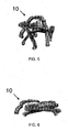
- FIGS. 5 and 6 illustrate the sensor assembly 10 in uncompressed and compressed states, respectively.
- the leg structures 18, 20 flex, with the lower leg structures 18 fitting beneath the upper leg structures 20.
- the flexing action causes the transducers 25, 29 to slide on the subject area. In instances where there is hair on the subject area, the sliding action helps position the transducers 25, 29 beneath the hair strands for better contact directly with skin or scalp. Since the leg structures 18, 20 within all of the probes 14a-c flatten, the present invention reduces the risk of injury to the subject, in contrast to prior art dry-electrode assemblies having straight fingers.
- FIG. 7 another exemplary embodiment of a transducer assembly 40 according to the present invention includes a support terminal 42 and six probes 44a, 44b, 44c, 44d, 44e and 44f, which are attached to and extend from the support terminal 42.
- the support terminal 42 supports the six probes 44a, 44b, 44c, 44d, 44e and 44f. In other versions of this other embodiment, there may be more or less than six probes.
- the support terminal 42 also serves as an attachment point for external signal connectors. Although the support terminal 42 is illustrated as circular in FIG. 4 , the support terminal 42 may be of any shape.
- an individual probe 44 includes only one leg structure 48.
- the leg structure 48 includes a branch 52, at which the probe 44 is connected to the support terminal 42, a flexible joint 54 and a foot 56, which supports a transducer 57.
- the leg structure 48 flexes outward at the joint 54, and cause the foot-supported transducers 55 to slide on the subject area. In instances where there is hair on the subject area, the sliding action helps position the transducer 57 beneath the hair strands for better contact directly with skin or scalp. Since all the leg structures 48 within all of the probes 44 flatten when sufficient pressure is applied to the support terminal 42, as shown in FIG. 9 , the present invention reduces the risk of injury to the subject, in contrast to prior art dry-electrode assemblies having straight fingers.
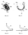
- a further exemplary embodiment of a transducer assembly 60 includes a support terminal 62 and five probes 64a, 64b, 64c, 64d and 64e, which are supported by and extend outward from the support terminal 62 in a direction that is non-perpendicular to the support terminal 62. In other versions of this other embodiment, there may be more or less than five probes.
- an individual probe 64 includes a single loop-shaped leg structure 66 having two terminals 68a, 68b, which are attached to the support terminal 62. At least part of the loop-shaped leg structure 66 is made of flexible material which is disposed so that leg structure 66 flexes outward from the support terminal 62 when pressure is applied to the support terminal 62.
- the loop-shaped leg structure 66 includes joints disposed in the regions adjacent the terminals 68a, 68b, wherein the joints enable the leg structure 66 to flex outward from the support terminal 62 when pressure is applied to the support terminal 62.
- a transducer 70 is disposed at the distal end of the leg structure 66 for sensing or stimulating the state of a particular property of a selected subject area when the transducer 70 is applied by the leg structure to the selected subject area when pressure is applied to the support terminal 62 to thereby cause the transducer 70 to slide on the subject area.
- loop shape of the leg structure 66 is that the flexing action is bettered constrained to only a radial, outward direction with respect to the support terminal 62 and thereby prevents the leg structure 66 from bending in a suboptimal direction (e.g., sideways), which may compromise its integrity.
- a second advantage of the loop shape is that that the transducer 70 can be made part of the loop, which enables the transducer 70 to bend under pressure and provide greater conformity and contact area to the surface of the subject.
- a generalized probe 80 having a transducer 82 at the distal end of the probe 80 is disposed at a non-perpendicular angle to a subject area 84 while being oriented in a non-parallel direction to an applied force D.
- a head cap, strap or other harness system usually supplies this force D perpendicular to the subject area 84.
- the force D causes the probe 80 to deflect in the direction S enabling the contact transducer 82 to slide on the subject area 84.
- the contact 82 is made of a conductive material to acquire electrical signals from the subject area 84.
- the sliding action enables the tip of the transducer 82 to push aside hair and achieve better contact to the subject area 84.
- the probe 80 simply flattens on its side and against the subject area 84 and thereby broadly distributes over the subject area 84.
- the sliding action of the current invention in combination with the ability of the probe 80 to flatten under extreme pressure enables the transducer 82 to both penetrate and push aside hair while maintaining comfort and safety.
- the support terminal and the probes of the transducer assembly are capable of transferring electrical signals between the transducer and an external device.
- the support terminal and the probes are made from nylon or any other elastomer plastics that are flexible and bendable; and a silver paint is applied to the surface to make the support terminal and probes electrically conductive.
- An alternative technique involves immersing a plastic support terminal and plastic probes in an electroplating bath that coats their surfaces with electrically conductive material.
- the entire transducer assembly can be made from a conductive material such as carbon filled plastic, conductive silver-silicone compounds or solid metal.
- an explicit joint is not required.
- the joint can simply be a flexing function provided by the leg structure being attached to the support terminal; or the flexibility function of the joint is inherent to the leg structure, such as when the leg structure is made of a sufficiently flexible material.
- the transducer assembly of the present invention is broadly applicable to a variety of other embodiments that involve placing a transducer on the surface of a person in addition to embodiments that are used for sensing a bioelectric potential.
- a thermistor is supported by the leg structures of the probes to sense head temperature through hair.
- Another application involves placing optical sensors at the distal ends of the leg structures for measuring blood oxygen saturation or near infrared spectroscopy.
- the transducer assembly is used to deliver electrical current, rather than or in addition to sensing bioelectric potential, for transcranial stimulation.
- the transducers are electrodes that are connected to the input of an EEG system; and multiple electrodes are disposed inside a headset cap, strap or harness to facilitate the placement of multiple channels on a subject.
- each electrode is typically be incorporated into a headset cap that can apply pressure to cause all the electrodes to simultaneously to slide on the respective subject areas and thereby enable rapid application of the pressure.
- the user When the recording is finished, the user simply removes the electrode and/or the headset, strap or harness.
Landscapes
- Life Sciences & Earth Sciences (AREA)
- Health & Medical Sciences (AREA)
- Medical Informatics (AREA)
- Biophysics (AREA)
- Pathology (AREA)
- Engineering & Computer Science (AREA)
- Biomedical Technology (AREA)
- Heart & Thoracic Surgery (AREA)
- Physics & Mathematics (AREA)
- Molecular Biology (AREA)
- Surgery (AREA)
- Animal Behavior & Ethology (AREA)
- General Health & Medical Sciences (AREA)
- Public Health (AREA)
- Veterinary Medicine (AREA)
- Measurement And Recording Of Electrical Phenomena And Electrical Characteristics Of The Living Body (AREA)
Claims (9)
- Signalwandler-Einrichtung (10, 40, 60), aufweisend:ein Halte-Anschlussteil (12, 42, 62) undwenigstens einen Fühler (14, 44, 64), der an dem Halte-Anschlussteil (12, 42, 62) angebracht ist und sich davon aus erstreckt,wobei der wenigstens eine Fühler (14, 44, 64) wenigstens eine Beinstruktur (18, 20, 48, 66) aufweist, die eine Elektrode (25, 29, 57, 70) hält, die an dem distalen Ende der Beinstruktur (18, 20, 48, 66) angeordnet ist zum Erfassen oder Stimulieren des Zustands einer bestimmten Eigenschaft eines ausgewählten Subjektbereichs, wenn die Elektrode (25, 29, 57, 70) von der Beinstruktur (18, 20, 48, 66) auf den ausgewählten Subjektbereich angewandt wird, undwobei die wenigstens eine Beinstruktur (18, 20, 48, 66) derart in Relation zu dem Halte-Anschlussteil angeordnet ist, dass sie in einem nicht-rechtwinkligen Winkel zu dem Subjektbereich angeordnet ist, wenn die Signalwandler-Einrichtung (10, 40, 60) auf den ausgewählten Subjektbereich angewandt wird, und wobei das Halte-Anschlussteil (12, 42, 62) und der wenigstens eine Fühler (14, 44, 64) aus einem Elastomer-Kunststoffmaterial gemacht sind, das flexibel und biegbar ist, dadurch gekennzeichnet, dassdie Fläche des Halte-Anschlussteils (12, 42, 62) und der wenigstens eine Fühler (14, 44, 64) leitfähig gemacht sind durch ein angewandtes, leitfähiges Material.
- Signalwandler-Einrichtung (10, 40, 60) gemäß Anspruch 1, wobei die wenigstens eine Beinstruktur (18, 20, 48, 66) angepasst ist, um sich zu biegen, wenn die Elektrode (25, 29, 57, 70) unter Druck auf den ausgewählten Subjektbereich angewandt wird, um dadurch die Elektrode (25, 29, 57, 70) zu veranlassen, an dem Subjektbereich zu gleiten.
- Signalwandler-Einrichtung (10, 40, 60) gemäß Anspruch 1 oder 2, wobei eine Mehrzahl der Fühler (14, 44, 64) angebracht sind, um sich von dem Halte-Anschlussteil (12, 42, 62) aus zu erstrecken.
- Signalwandler-Einrichtung (10) gemäß Anspruch 3, wobei einzelne der Fühler (14) eine Mehrzahl der Beinstrukturen (18, 20) aufweisen.
- Signalwandler-Einrichtung (10) gemäß Anspruch 4,
wobei einzelne der Fühler (14) eine obere Beinstruktur (20) und eine untere Beinstruktur (18) aufweisen, und
wobei einzelne der Beinstrukturen (18, 20) aufweisen einen Fuß (24, 28), der eine Elektrode (25, 29) hält, und eine flexible Verbindung (26, 30), so dass, wenn die jeweiligen Elektroden (25, 29) in Kontakt mit einem Subjektbereich sind und Druck auf das Halte-Anschlussteil (12) angewandt wird, die obere (20) und die untere (18) Beinstruktur sich an ihrer jeweiligen Verbindung (26, 30) biegen und die fuß-gehaltenen Elektroden (25, 29) veranlassen, an dem Subjektbereich zu gleiten. - Signalwandler-Einrichtung (10) gemäß Anspruch 4,
wobei einzelne der Fühler (14) eine obere Beinstruktur (20) und eine untere Beinstruktur (18) aufweisen, und
wobei die untere Beinstruktur (18) von einem Fühler (14) angeordnet ist, um die obere Beinstruktur (20) eines benachbarten Fühlers (14) zu unterkreuzen, um die radiale Ausdehnung der Signalwandler-Einrichtung (10) zu minimieren, wenn jede dieser Beinstrukturen (18, 20) sich biegt. - Signalwandler-Einrichtung (10) gemäß Anspruch 3,
wobei einzelne der Proben (14) eine obere Beinstruktur (20) und eine untere Beinstruktur (18) aufweisen, und
wobei einzelne der Beinstrukturen (18, 20) aufweisen einen Fuß (24, 28), welcher eine Elektrode (25, 29) hält, und eine flexible Verbindung (26, 30), so dass, wenn die jeweiligen Elektroden (25, 29) in Kontakt mit einem Subjektbereich sind und Druck auf das Halte-Anschlussteil (12) angewandt wird, die obere und die untere Beinstruktur (18, 20) sich an ihren jeweiligen Verbindungen (26, 30) biegen und die fuß-gehaltenen Elektroden (25, 29) veranlassen, an dem Subjektbereich zu gleiten. - Signalwandler-Einrichtung (60) gemäß Anspruch 3, wobei einzelne der Fühler (64) aufweisen eine schlaufen-förmige Beinstruktur (66), die sich von dem Halte-Anschlussbauteil (62) aus in einer Richtung erstreckt, die nicht rechtwinklig zu dem Halte-Anschlussteil (62) ist.
- Signalwandler-Einrichtung (10) gemäß Anspruch 1 oder 2,
wobei ein einzelner Fühler (14) eine obere Beinstruktur (20) und eine untere Beinstruktur (18) aufweist, und
wobei einzelne der Beinstrukturen (18, 20) aufweisen einen Fuß (24, 28), welcher eine Elektrode (25, 29) hält, und eine flexible Verbindung (26, 30), so dass, wenn die jeweiligen Elektroden (25, 29) in Kontakt mit dem Subjektbereich sind und Druck auf das Halte-Anschlussteil (12) angewandt wird, die obere und die untere Beinstruktur (18, 20) sich an ihren jeweiligen Verbindungen (26, 30) biegen und die fuß-gehaltenen Elektroden (25, 29) zu veranlassen, an dem Subjektbereich zu gleiten.
Applications Claiming Priority (3)
| Application Number | Priority Date | Filing Date | Title |
|---|---|---|---|
| US201261612867P | 2012-03-19 | 2012-03-19 | |
| US201261652073P | 2012-05-25 | 2012-05-25 | |
| PCT/US2013/032015 WO2013142316A1 (en) | 2012-03-19 | 2013-03-15 | Transducer assemblies for dry applications of transducers |
Publications (3)
| Publication Number | Publication Date |
|---|---|
| EP2827770A1 EP2827770A1 (de) | 2015-01-28 |
| EP2827770A4 EP2827770A4 (de) | 2015-11-11 |
| EP2827770B1 true EP2827770B1 (de) | 2018-05-16 |
Family
ID=49223248
Family Applications (1)
| Application Number | Title | Priority Date | Filing Date |
|---|---|---|---|
| EP13764511.5A Active EP2827770B1 (de) | 2012-03-19 | 2013-03-15 | Wandleranordnungen für trockenanwendungen von wandlern |
Country Status (6)
| Country | Link |
|---|---|
| US (1) | US9314183B2 (de) |
| EP (1) | EP2827770B1 (de) |
| JP (1) | JP6077639B2 (de) |
| CN (1) | CN104470424B (de) |
| CA (1) | CA2866757C (de) |
| WO (1) | WO2013142316A1 (de) |
Families Citing this family (24)
| Publication number | Priority date | Publication date | Assignee | Title |
|---|---|---|---|---|
| US12201427B2 (en) | 2012-06-14 | 2025-01-21 | Medibotics Llc | Headband with brain activity sensors |
| US11850052B2 (en) | 2014-01-28 | 2023-12-26 | Medibotics Llc | Dry EEG electrode for use on a hair-covered portion of a person's head |
| TWI547263B (zh) * | 2013-03-22 | 2016-09-01 | 國立交通大學 | 線接面式乾電極 |
| CN104799853A (zh) * | 2015-04-09 | 2015-07-29 | 中国科学院半导体研究所 | 用于脑电信号记录的韧性爪式干电极及制备方法 |
| ITUB20154029A1 (it) | 2015-09-30 | 2017-03-30 | Ab Medica Holding S P A | Dispositivo per la registrazione di video elettroencefalogrammi |
| WO2017065196A1 (ja) * | 2015-10-13 | 2017-04-20 | ニッタ株式会社 | 脳波測定用電極 |
| WO2017065195A1 (ja) * | 2015-10-13 | 2017-04-20 | ニッタ株式会社 | 脳波測定用電極 |
| US20160129238A1 (en) * | 2016-01-14 | 2016-05-12 | Joel Steven Goldberg | Method to optimize electrode placement for cranial electrical stmulation |
| CN106419913A (zh) * | 2016-08-31 | 2017-02-22 | 苏州格林泰克科技有限公司 | 一种用于生物电信号感测的半干电极、系统以及方法 |
| RU177707U1 (ru) * | 2017-05-25 | 2018-03-06 | Общество С Ограниченной Ответственностью Инженерный Центр "Комплекс-М" | Устройство для регистрации электроэнцефалографических сигналов |
| EP3415081B1 (de) * | 2017-06-12 | 2023-12-20 | Dreem | Elektrode, tragbare-anordnung und system |
| JP6982304B2 (ja) * | 2017-11-30 | 2021-12-17 | 東海光学株式会社 | 脳活動計測用電極、その電極を使用した頭部装着装置及び脳活動計測システム |
| WO2019108968A1 (en) | 2017-12-01 | 2019-06-06 | Zeto, Inc. | Headset and electrodes for sensing bioelectrical potential and methods of operation thereof |
| FR3077723B1 (fr) | 2018-02-15 | 2020-03-13 | Centre National De La Recherche Scientifique | Electroencephalographes portatifs |
| FR3086527B1 (fr) | 2018-10-02 | 2023-01-06 | Urgotech | Capteur pour mesurer un potentiel biologique |
| JP6708322B1 (ja) * | 2018-10-26 | 2020-06-10 | 住友ベークライト株式会社 | 生体用電極、生体センサーおよび生体信号測定システム |
| JP6931738B2 (ja) * | 2018-11-09 | 2021-09-08 | 住友ベークライト株式会社 | 生体用電極、生体センサーおよび生体信号測定システム |
| WO2020246358A1 (ja) * | 2019-06-06 | 2020-12-10 | Nok株式会社 | 生体電極 |
| GB2589827B (en) * | 2019-10-04 | 2022-09-14 | Neuroconcise Ltd | Flexible electrical measurement apparatus |
| WO2021254601A1 (en) * | 2020-06-16 | 2021-12-23 | IDUN Technologies AG | Three-dimensional electrode arrangement |
| US20230263447A1 (en) | 2020-09-03 | 2023-08-24 | Dätwyler Schweiz Ag | Soft and dry electrode |
| CN113208598A (zh) * | 2021-04-22 | 2021-08-06 | 北京脑陆科技有限公司 | 生物电信号的采集装置 |
| CH720063A1 (de) | 2022-09-26 | 2024-04-15 | Daetwyler Schweiz Ag | Weiche und trockene Elektrode |
| US20240345406A1 (en) * | 2023-04-11 | 2024-10-17 | Cognixion Corporation | Adaptable high performance neural interface electrodes that conform to human anatomy |
Citations (1)
| Publication number | Priority date | Publication date | Assignee | Title |
|---|---|---|---|---|
| DE102010017415A1 (de) * | 2010-06-17 | 2011-12-22 | Yakob Badower | Sensorsystem zum nicht-invasiven Erfassen von elektromagnetischen Signalen biologischen Ursprungs am menschlichen Körper sowie Kopf-Sensorsystem |
Family Cites Families (17)
| Publication number | Priority date | Publication date | Assignee | Title |
|---|---|---|---|---|
| US2426958A (en) * | 1944-12-27 | 1947-09-02 | Jr George A Ulett | Electrode holder for use in electroencephalography |
| US3735753A (en) * | 1971-11-09 | 1973-05-29 | Humetrics Corp | Head harness for eeg electrodes |
| US4709702A (en) * | 1985-04-25 | 1987-12-01 | Westinghouse Electric Corp. | Electroencephalographic cap |
| US5038782A (en) * | 1986-12-16 | 1991-08-13 | Sam Technology, Inc. | Electrode system for brain wave detection |
| US4967038A (en) * | 1986-12-16 | 1990-10-30 | Sam Techology Inc. | Dry electrode brain wave recording system |
| US5348006A (en) * | 1991-08-26 | 1994-09-20 | Electrical Geodesics, Inc. | Head sensor positioning pedestal |
| CN2275430Y (zh) * | 1996-12-23 | 1998-03-04 | 徐冬梅 | 脑电图电极固定帽 |
| US6201982B1 (en) * | 1998-07-02 | 2001-03-13 | Baltimore Biomedical, Inc. | Quick-placement electroencephalogram (EEG) electrode |
| JP2003260034A (ja) * | 2002-03-08 | 2003-09-16 | Japan Aqua Tec Co Ltd | 脳波測定用ヘルメット |
| JP2005152415A (ja) * | 2003-11-27 | 2005-06-16 | Olympus Corp | 生体信号検出電極及び生体信号検出装置 |
| TW200740410A (en) * | 2006-03-22 | 2007-11-01 | Emotiv Systems Pty Ltd | Electrode and electrode headset |
| WO2008067839A1 (en) * | 2006-12-08 | 2008-06-12 | Fraunhofer-Gesellschaft zur Förderung der angewandten Forschung e.V. | Dry electrode cap for electro-encephalography |
| WO2008153713A1 (en) | 2007-05-23 | 2008-12-18 | Quantum Applied Science And Research, Inc. | Sensor mounting system |
| TW200922524A (en) * | 2007-11-22 | 2009-06-01 | Univ Chung Yuan Christian | Contact-type detection device |
| DE102009005414A1 (de) * | 2009-01-19 | 2010-08-12 | Charité - Universitätsmedizin Berlin | Elektrodenanordnung zum nicht-invasiven Messen bioelektrischer Signale |
| JP5476570B2 (ja) * | 2010-07-15 | 2014-04-23 | 日本電信電話株式会社 | 剣山型乾電極及びその作製方法 |
| US8392250B2 (en) | 2010-08-09 | 2013-03-05 | The Nielsen Company (Us), Llc | Neuro-response evaluated stimulus in virtual reality environments |
-
2013
- 2013-03-15 JP JP2015501801A patent/JP6077639B2/ja active Active
- 2013-03-15 CN CN201380015527.5A patent/CN104470424B/zh active Active
- 2013-03-15 EP EP13764511.5A patent/EP2827770B1/de active Active
- 2013-03-15 WO PCT/US2013/032015 patent/WO2013142316A1/en not_active Ceased
- 2013-03-15 CA CA2866757A patent/CA2866757C/en active Active
- 2013-03-15 US US13/982,724 patent/US9314183B2/en active Active
Patent Citations (1)
| Publication number | Priority date | Publication date | Assignee | Title |
|---|---|---|---|---|
| DE102010017415A1 (de) * | 2010-06-17 | 2011-12-22 | Yakob Badower | Sensorsystem zum nicht-invasiven Erfassen von elektromagnetischen Signalen biologischen Ursprungs am menschlichen Körper sowie Kopf-Sensorsystem |
Also Published As
| Publication number | Publication date |
|---|---|
| US20150141788A1 (en) | 2015-05-21 |
| CN104470424A (zh) | 2015-03-25 |
| JP6077639B2 (ja) | 2017-02-08 |
| CA2866757A1 (en) | 2013-09-26 |
| JP2015510823A (ja) | 2015-04-13 |
| EP2827770A4 (de) | 2015-11-11 |
| US9314183B2 (en) | 2016-04-19 |
| WO2013142316A1 (en) | 2013-09-26 |
| EP2827770A1 (de) | 2015-01-28 |
| CA2866757C (en) | 2017-01-03 |
| CN104470424B (zh) | 2017-09-08 |
Similar Documents
| Publication | Publication Date | Title |
|---|---|---|
| EP2827770B1 (de) | Wandleranordnungen für trockenanwendungen von wandlern | |
| US12193824B2 (en) | Method and system for obtaining signals from dry EEG electrodes | |
| EP2251660B1 (de) | Doppeltemperatursensor | |
| US8706182B2 (en) | Biosignal detecting electrode and biosignal detecting device equipped therewith | |
| US20250375139A1 (en) | Portable electroencephalography devices | |
| EP3585255B1 (de) | Vorrichtung und verfahren zur durchführung einer elektroenzephalografie | |
| JP2009530064A (ja) | 電極および電極ヘッドセット | |
| KR20120049188A (ko) | 생체 신호 측정용 장구 | |
| EP3415081B1 (de) | Elektrode, tragbare-anordnung und system | |
| WO2009134763A1 (en) | Biomedical sensors usable on un-prepared contact surfaces | |
| CN107257657A (zh) | 脑电图电极 | |
| KR20140001612A (ko) | 다양한 생체신호측정을 위한 유연성 금속의 생체신호검출용 센서전극 | |
| US7277743B2 (en) | Patient monitoring system | |
| Damalerio et al. | Development of dry EEG electrodes and dry EEG cap for neuromonitoring | |
| US10004419B2 (en) | Electrode for measuring living body signal | |
| RU177707U1 (ru) | Устройство для регистрации электроэнцефалографических сигналов | |
| EP4736766A1 (de) | Elektroenzephalogrammmessvorrichtung | |
| WO2025004931A1 (ja) | 脳波測定装置 |
Legal Events
| Date | Code | Title | Description |
|---|---|---|---|
| PUAI | Public reference made under article 153(3) epc to a published international application that has entered the european phase |
Free format text: ORIGINAL CODE: 0009012 |
|
| 17P | Request for examination filed |
Effective date: 20140925 |
|
| AK | Designated contracting states |
Kind code of ref document: A1 Designated state(s): AL AT BE BG CH CY CZ DE DK EE ES FI FR GB GR HR HU IE IS IT LI LT LU LV MC MK MT NL NO PL PT RO RS SE SI SK SM TR |
|
| AX | Request for extension of the european patent |
Extension state: BA ME |
|
| RIN1 | Information on inventor provided before grant (corrected) |
Inventor name: CHI, YU MIKE Inventor name: ELCONIN, MICHAEL HENRY Inventor name: KERTH, TREVOR AUSTIN |
|
| RIN1 | Information on inventor provided before grant (corrected) |
Inventor name: CHI, YU MIKE Inventor name: ELCONIN, MICHAEL HENRY Inventor name: KERTH, TREVOR AUSTIN |
|
| DAX | Request for extension of the european patent (deleted) | ||
| RA4 | Supplementary search report drawn up and despatched (corrected) |
Effective date: 20151013 |
|
| RIC1 | Information provided on ipc code assigned before grant |
Ipc: A61B 5/0478 20060101AFI20151007BHEP |
|
| 17Q | First examination report despatched |
Effective date: 20160715 |
|
| STAA | Information on the status of an ep patent application or granted ep patent |
Free format text: STATUS: EXAMINATION IS IN PROGRESS |
|
| GRAP | Despatch of communication of intention to grant a patent |
Free format text: ORIGINAL CODE: EPIDOSNIGR1 |
|
| STAA | Information on the status of an ep patent application or granted ep patent |
Free format text: STATUS: GRANT OF PATENT IS INTENDED |
|
| INTG | Intention to grant announced |
Effective date: 20171201 |
|
| GRAS | Grant fee paid |
Free format text: ORIGINAL CODE: EPIDOSNIGR3 |
|
| GRAA | (expected) grant |
Free format text: ORIGINAL CODE: 0009210 |
|
| STAA | Information on the status of an ep patent application or granted ep patent |
Free format text: STATUS: THE PATENT HAS BEEN GRANTED |
|
| AK | Designated contracting states |
Kind code of ref document: B1 Designated state(s): AL AT BE BG CH CY CZ DE DK EE ES FI FR GB GR HR HU IE IS IT LI LT LU LV MC MK MT NL NO PL PT RO RS SE SI SK SM TR |
|
| REG | Reference to a national code |
Ref country code: GB Ref legal event code: FG4D |
|
| REG | Reference to a national code |
Ref country code: CH Ref legal event code: EP |
|
| REG | Reference to a national code |
Ref country code: IE Ref legal event code: FG4D |
|
| REG | Reference to a national code |
Ref country code: DE Ref legal event code: R096 Ref document number: 602013037556 Country of ref document: DE |
|
| REG | Reference to a national code |
Ref country code: AT Ref legal event code: REF Ref document number: 998803 Country of ref document: AT Kind code of ref document: T Effective date: 20180615 |
|
| REG | Reference to a national code |
Ref country code: NL Ref legal event code: MP Effective date: 20180516 |
|
| REG | Reference to a national code |
Ref country code: LT Ref legal event code: MG4D |
|
| PG25 | Lapsed in a contracting state [announced via postgrant information from national office to epo] |
Ref country code: NO Free format text: LAPSE BECAUSE OF FAILURE TO SUBMIT A TRANSLATION OF THE DESCRIPTION OR TO PAY THE FEE WITHIN THE PRESCRIBED TIME-LIMIT Effective date: 20180816 Ref country code: LT Free format text: LAPSE BECAUSE OF FAILURE TO SUBMIT A TRANSLATION OF THE DESCRIPTION OR TO PAY THE FEE WITHIN THE PRESCRIBED TIME-LIMIT Effective date: 20180516 Ref country code: ES Free format text: LAPSE BECAUSE OF FAILURE TO SUBMIT A TRANSLATION OF THE DESCRIPTION OR TO PAY THE FEE WITHIN THE PRESCRIBED TIME-LIMIT Effective date: 20180516 Ref country code: SE Free format text: LAPSE BECAUSE OF FAILURE TO SUBMIT A TRANSLATION OF THE DESCRIPTION OR TO PAY THE FEE WITHIN THE PRESCRIBED TIME-LIMIT Effective date: 20180516 Ref country code: FI Free format text: LAPSE BECAUSE OF FAILURE TO SUBMIT A TRANSLATION OF THE DESCRIPTION OR TO PAY THE FEE WITHIN THE PRESCRIBED TIME-LIMIT Effective date: 20180516 Ref country code: BG Free format text: LAPSE BECAUSE OF FAILURE TO SUBMIT A TRANSLATION OF THE DESCRIPTION OR TO PAY THE FEE WITHIN THE PRESCRIBED TIME-LIMIT Effective date: 20180816 |
|
| PG25 | Lapsed in a contracting state [announced via postgrant information from national office to epo] |
Ref country code: RS Free format text: LAPSE BECAUSE OF FAILURE TO SUBMIT A TRANSLATION OF THE DESCRIPTION OR TO PAY THE FEE WITHIN THE PRESCRIBED TIME-LIMIT Effective date: 20180516 Ref country code: HR Free format text: LAPSE BECAUSE OF FAILURE TO SUBMIT A TRANSLATION OF THE DESCRIPTION OR TO PAY THE FEE WITHIN THE PRESCRIBED TIME-LIMIT Effective date: 20180516 Ref country code: LV Free format text: LAPSE BECAUSE OF FAILURE TO SUBMIT A TRANSLATION OF THE DESCRIPTION OR TO PAY THE FEE WITHIN THE PRESCRIBED TIME-LIMIT Effective date: 20180516 Ref country code: NL Free format text: LAPSE BECAUSE OF FAILURE TO SUBMIT A TRANSLATION OF THE DESCRIPTION OR TO PAY THE FEE WITHIN THE PRESCRIBED TIME-LIMIT Effective date: 20180516 Ref country code: GR Free format text: LAPSE BECAUSE OF FAILURE TO SUBMIT A TRANSLATION OF THE DESCRIPTION OR TO PAY THE FEE WITHIN THE PRESCRIBED TIME-LIMIT Effective date: 20180817 |
|
| REG | Reference to a national code |
Ref country code: AT Ref legal event code: MK05 Ref document number: 998803 Country of ref document: AT Kind code of ref document: T Effective date: 20180516 |
|
| PG25 | Lapsed in a contracting state [announced via postgrant information from national office to epo] |
Ref country code: EE Free format text: LAPSE BECAUSE OF FAILURE TO SUBMIT A TRANSLATION OF THE DESCRIPTION OR TO PAY THE FEE WITHIN THE PRESCRIBED TIME-LIMIT Effective date: 20180516 Ref country code: PL Free format text: LAPSE BECAUSE OF FAILURE TO SUBMIT A TRANSLATION OF THE DESCRIPTION OR TO PAY THE FEE WITHIN THE PRESCRIBED TIME-LIMIT Effective date: 20180516 Ref country code: DK Free format text: LAPSE BECAUSE OF FAILURE TO SUBMIT A TRANSLATION OF THE DESCRIPTION OR TO PAY THE FEE WITHIN THE PRESCRIBED TIME-LIMIT Effective date: 20180516 Ref country code: SK Free format text: LAPSE BECAUSE OF FAILURE TO SUBMIT A TRANSLATION OF THE DESCRIPTION OR TO PAY THE FEE WITHIN THE PRESCRIBED TIME-LIMIT Effective date: 20180516 Ref country code: CZ Free format text: LAPSE BECAUSE OF FAILURE TO SUBMIT A TRANSLATION OF THE DESCRIPTION OR TO PAY THE FEE WITHIN THE PRESCRIBED TIME-LIMIT Effective date: 20180516 Ref country code: AT Free format text: LAPSE BECAUSE OF FAILURE TO SUBMIT A TRANSLATION OF THE DESCRIPTION OR TO PAY THE FEE WITHIN THE PRESCRIBED TIME-LIMIT Effective date: 20180516 Ref country code: RO Free format text: LAPSE BECAUSE OF FAILURE TO SUBMIT A TRANSLATION OF THE DESCRIPTION OR TO PAY THE FEE WITHIN THE PRESCRIBED TIME-LIMIT Effective date: 20180516 |
|
| REG | Reference to a national code |
Ref country code: DE Ref legal event code: R097 Ref document number: 602013037556 Country of ref document: DE |
|
| PG25 | Lapsed in a contracting state [announced via postgrant information from national office to epo] |
Ref country code: SM Free format text: LAPSE BECAUSE OF FAILURE TO SUBMIT A TRANSLATION OF THE DESCRIPTION OR TO PAY THE FEE WITHIN THE PRESCRIBED TIME-LIMIT Effective date: 20180516 Ref country code: IT Free format text: LAPSE BECAUSE OF FAILURE TO SUBMIT A TRANSLATION OF THE DESCRIPTION OR TO PAY THE FEE WITHIN THE PRESCRIBED TIME-LIMIT Effective date: 20180516 |
|
| PLBE | No opposition filed within time limit |
Free format text: ORIGINAL CODE: 0009261 |
|
| STAA | Information on the status of an ep patent application or granted ep patent |
Free format text: STATUS: NO OPPOSITION FILED WITHIN TIME LIMIT |
|
| 26N | No opposition filed |
Effective date: 20190219 |
|
| PG25 | Lapsed in a contracting state [announced via postgrant information from national office to epo] |
Ref country code: SI Free format text: LAPSE BECAUSE OF FAILURE TO SUBMIT A TRANSLATION OF THE DESCRIPTION OR TO PAY THE FEE WITHIN THE PRESCRIBED TIME-LIMIT Effective date: 20180516 |
|
| PG25 | Lapsed in a contracting state [announced via postgrant information from national office to epo] |
Ref country code: MC Free format text: LAPSE BECAUSE OF FAILURE TO SUBMIT A TRANSLATION OF THE DESCRIPTION OR TO PAY THE FEE WITHIN THE PRESCRIBED TIME-LIMIT Effective date: 20180516 |
|
| REG | Reference to a national code |
Ref country code: CH Ref legal event code: PL |
|
| PG25 | Lapsed in a contracting state [announced via postgrant information from national office to epo] |
Ref country code: AL Free format text: LAPSE BECAUSE OF FAILURE TO SUBMIT A TRANSLATION OF THE DESCRIPTION OR TO PAY THE FEE WITHIN THE PRESCRIBED TIME-LIMIT Effective date: 20180516 Ref country code: LU Free format text: LAPSE BECAUSE OF NON-PAYMENT OF DUE FEES Effective date: 20190315 |
|
| REG | Reference to a national code |
Ref country code: BE Ref legal event code: MM Effective date: 20190331 |
|
| PG25 | Lapsed in a contracting state [announced via postgrant information from national office to epo] |
Ref country code: CH Free format text: LAPSE BECAUSE OF NON-PAYMENT OF DUE FEES Effective date: 20190331 Ref country code: LI Free format text: LAPSE BECAUSE OF NON-PAYMENT OF DUE FEES Effective date: 20190331 Ref country code: IE Free format text: LAPSE BECAUSE OF NON-PAYMENT OF DUE FEES Effective date: 20190315 |
|
| PG25 | Lapsed in a contracting state [announced via postgrant information from national office to epo] |
Ref country code: BE Free format text: LAPSE BECAUSE OF NON-PAYMENT OF DUE FEES Effective date: 20190331 |
|
| PG25 | Lapsed in a contracting state [announced via postgrant information from national office to epo] |
Ref country code: TR Free format text: LAPSE BECAUSE OF FAILURE TO SUBMIT A TRANSLATION OF THE DESCRIPTION OR TO PAY THE FEE WITHIN THE PRESCRIBED TIME-LIMIT Effective date: 20180516 |
|
| PG25 | Lapsed in a contracting state [announced via postgrant information from national office to epo] |
Ref country code: PT Free format text: LAPSE BECAUSE OF FAILURE TO SUBMIT A TRANSLATION OF THE DESCRIPTION OR TO PAY THE FEE WITHIN THE PRESCRIBED TIME-LIMIT Effective date: 20180917 Ref country code: MT Free format text: LAPSE BECAUSE OF NON-PAYMENT OF DUE FEES Effective date: 20190315 |
|
| REG | Reference to a national code |
Ref country code: DE Ref legal event code: R079 Ref document number: 602013037556 Country of ref document: DE Free format text: PREVIOUS MAIN CLASS: A61B0005047800 Ipc: A61B0005291000 |
|
| PG25 | Lapsed in a contracting state [announced via postgrant information from national office to epo] |
Ref country code: CY Free format text: LAPSE BECAUSE OF FAILURE TO SUBMIT A TRANSLATION OF THE DESCRIPTION OR TO PAY THE FEE WITHIN THE PRESCRIBED TIME-LIMIT Effective date: 20180516 |
|
| PG25 | Lapsed in a contracting state [announced via postgrant information from national office to epo] |
Ref country code: IS Free format text: LAPSE BECAUSE OF FAILURE TO SUBMIT A TRANSLATION OF THE DESCRIPTION OR TO PAY THE FEE WITHIN THE PRESCRIBED TIME-LIMIT Effective date: 20180916 |
|
| PG25 | Lapsed in a contracting state [announced via postgrant information from national office to epo] |
Ref country code: HU Free format text: LAPSE BECAUSE OF FAILURE TO SUBMIT A TRANSLATION OF THE DESCRIPTION OR TO PAY THE FEE WITHIN THE PRESCRIBED TIME-LIMIT; INVALID AB INITIO Effective date: 20130315 |
|
| PG25 | Lapsed in a contracting state [announced via postgrant information from national office to epo] |
Ref country code: MK Free format text: LAPSE BECAUSE OF FAILURE TO SUBMIT A TRANSLATION OF THE DESCRIPTION OR TO PAY THE FEE WITHIN THE PRESCRIBED TIME-LIMIT Effective date: 20180516 |
|
| REG | Reference to a national code |
Ref country code: GB Ref legal event code: 732E Free format text: REGISTERED BETWEEN 20250410 AND 20250416 |
|
| REG | Reference to a national code |
Ref country code: DE Ref legal event code: R081 Ref document number: 602013037556 Country of ref document: DE Owner name: MYNDFULL CARE HOLDINGS, LLC, SAN DIEGO, US Free format text: FORMER OWNER: COGNIONICS, INC., SAN DIEGO, CALIF., US |
|
| PGFP | Annual fee paid to national office [announced via postgrant information from national office to epo] |
Ref country code: GB Payment date: 20260316 Year of fee payment: 14 |
|
| PGFP | Annual fee paid to national office [announced via postgrant information from national office to epo] |
Ref country code: DE Payment date: 20260319 Year of fee payment: 14 |
|
| PGFP | Annual fee paid to national office [announced via postgrant information from national office to epo] |
Ref country code: FR Payment date: 20260320 Year of fee payment: 14 |