EP2827477B1 - Generatoranordnung für hohe axiale Schwingungseingaben - Google Patents
Generatoranordnung für hohe axiale Schwingungseingaben Download PDFInfo
- Publication number
- EP2827477B1 EP2827477B1 EP14175327.7A EP14175327A EP2827477B1 EP 2827477 B1 EP2827477 B1 EP 2827477B1 EP 14175327 A EP14175327 A EP 14175327A EP 2827477 B1 EP2827477 B1 EP 2827477B1
- Authority
- EP
- European Patent Office
- Prior art keywords
- bearing
- assembly
- generator
- bearing assembly
- shaft
- Prior art date
- Legal status (The legal status is an assumption and is not a legal conclusion. Google has not performed a legal analysis and makes no representation as to the accuracy of the status listed.)
- Active
Links
Images


Classifications
-
- F—MECHANICAL ENGINEERING; LIGHTING; HEATING; WEAPONS; BLASTING
- F16—ENGINEERING ELEMENTS AND UNITS; GENERAL MEASURES FOR PRODUCING AND MAINTAINING EFFECTIVE FUNCTIONING OF MACHINES OR INSTALLATIONS; THERMAL INSULATION IN GENERAL
- F16C—SHAFTS; FLEXIBLE SHAFTS; ELEMENTS OR CRANKSHAFT MECHANISMS; ROTARY BODIES OTHER THAN GEARING ELEMENTS; BEARINGS
- F16C33/00—Parts of bearings; Special methods for making bearings or parts thereof
- F16C33/30—Parts of ball or roller bearings
- F16C33/58—Raceways; Race rings
-
- H—ELECTRICITY
- H02—GENERATION; CONVERSION OR DISTRIBUTION OF ELECTRIC POWER
- H02K—DYNAMO-ELECTRIC MACHINES
- H02K5/00—Casings; Enclosures; Supports
- H02K5/04—Casings or enclosures characterised by the shape, form or construction thereof
- H02K5/16—Means for supporting bearings, e.g. insulating supports or means for fitting bearings in the bearing-shields
- H02K5/173—Means for supporting bearings, e.g. insulating supports or means for fitting bearings in the bearing-shields using bearings with rolling contact, e.g. ball bearings
-
- F—MECHANICAL ENGINEERING; LIGHTING; HEATING; WEAPONS; BLASTING
- F16—ENGINEERING ELEMENTS AND UNITS; GENERAL MEASURES FOR PRODUCING AND MAINTAINING EFFECTIVE FUNCTIONING OF MACHINES OR INSTALLATIONS; THERMAL INSULATION IN GENERAL
- F16C—SHAFTS; FLEXIBLE SHAFTS; ELEMENTS OR CRANKSHAFT MECHANISMS; ROTARY BODIES OTHER THAN GEARING ELEMENTS; BEARINGS
- F16C19/00—Bearings with rolling contact, for exclusively rotary movement
- F16C19/02—Bearings with rolling contact, for exclusively rotary movement with bearing balls essentially of the same size in one or more circular rows
- F16C19/04—Bearings with rolling contact, for exclusively rotary movement with bearing balls essentially of the same size in one or more circular rows for radial load mainly
-
- H—ELECTRICITY
- H02—GENERATION; CONVERSION OR DISTRIBUTION OF ELECTRIC POWER
- H02K—DYNAMO-ELECTRIC MACHINES
- H02K5/00—Casings; Enclosures; Supports
- H02K5/04—Casings or enclosures characterised by the shape, form or construction thereof
- H02K5/16—Means for supporting bearings, e.g. insulating supports or means for fitting bearings in the bearing-shields
- H02K5/161—Means for supporting bearings, e.g. insulating supports or means for fitting bearings in the bearing-shields radially supporting the rotary shaft at both ends of the rotor
-
- H—ELECTRICITY
- H02—GENERATION; CONVERSION OR DISTRIBUTION OF ELECTRIC POWER
- H02K—DYNAMO-ELECTRIC MACHINES
- H02K5/00—Casings; Enclosures; Supports
- H02K5/24—Casings; Enclosures; Supports specially adapted for suppression or reduction of noise or vibrations
Definitions
- the present invention generally relates to generator assemblies, and more particularly, a generator assembly for high axial vibration input.
- a conventional generator assembly may utilize two ball bearings preloaded with a spring washer.
- one bearing may usually be clamped to the housing structure while the other bearing may float axially. In conventional machines, with lower generator operating frequencies, this may not be a problem.
- the rotor may move causing very high amplitudes at a given sine input as the rotor displacement may be greater than the internal bearing clearance. As a result, the rotor may become fully clamped as a result and may move with the housing with an extreme resonant response.
- Rotor momentum may generate very high loads on a bearing liner on one side of the bearing and a bearing retainer on the other. The high loads may cause surrounding parts of the bearing to fail, for example, the clamping bolts.
- European Patent Application, publication number EP0712996A1 discloses a ram air turbine mounted in-line with a power supply unit such as an electrical generator and / or an hydraulic pump.
- the ram air turbine includes a turbine shaft supported for rotation by bearings within a generator housing, wherein a rear end of the turbine shaft and a generator shaft are supported by a common bearing, and further wherein the forwards ends of the turbine and generator shafts are supported by a pair of bearings separated by a resilient bearing mount.
- UK Patent Application, publication number GB2279819A discloses brush gear assemblies mounted within a resilient insulating ring which is secured to a motor end plate by means of screws and recessed eyelets.
- US patent 8791609 B2 discloses vibration damping for an electric device including wherein at least one damping device is provided between a stator and a rotor of a generator or motor.
- the present invention generally provides vibration protection for a bearing assembly in a generator which may be particularly beneficial in high frequency operation environments. For example, helicopters, tanks, etc. may use generators whose operation may induce relatively high vibration output. High amplitudes of vibration may cause deleterious effects on the generator parts causing breakdown. Exemplary embodiments of the present invention may anticipate potentially destructive harmonics in the generator and may provide for a safer operating environment under high frequency generator operations.
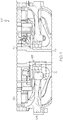
- the generator assembly 100 generally includes a housing 105, a rotor 110, a stator 120, and a bearing assembly 125.
- the rotor 110 includes a shaft 115 disposed to move axially through the housing 105 in response to the rotor 110 being driven by excitation of the stator 120 or an external source, for example, a source external to the generator assembly 100 (e.g. vibration frequencies generated by engine rotor (not shown).
- FIG. 2 shows a bearing liner 130 spaced from the bearing assembly 125 during a dynamic condition under use.
- Figure 3 shows the bearing liner 130 abutting the bearing assembly 125 during an assembly condition as a preload may push the bearing assembly 125 toward a surface of the bearing liner 130.
- the generator assembly 100 is configured to accommodate axial movement of the bearing assembly 125 induced by generator operation under rotation of the shaft 115.
- the bearing liner 130 is shown between the housing 105 and the bearing assembly 125.
- the bearing liner 130 is configured to provide clearance between the bearing liner 130 and the bearing assembly 125.
- the amount of clearance between the bearing assembly 125 and the bearing liner 130 may correspond to an amount of space needed to avoid harmonic vibration in the bearing assembly 125 with the surrounding elements of the generator assembly 100 at the operating frequency of the shaft 115.
- Portion 135 of the bearing liner 130 is shown spaced from an axial end 127 of the bearing assembly 125.
- the axial end 127 is shown orthogonal to an axis of rotation of the shaft 115.
- the portion 135 projects over the axial end 127 and is also orthogonal to the shaft 115.
- the portion 135 may cover some or the entire axial end 127.
- the clearance provided by the bearing liner 130 may change the generator assembly's 100 natural vibration frequency and amplitude.
- the bearing assembly 125 may move axially (relative to the rotation of the shaft 115) without encouraging amplified vibration with surrounding elements.
- a bearing retainer 140 is shown adjacent the bearing assembly 125.
- the bearing retainer 140 is configured to dampen axial movement of the bearing assembly 125, and may be particularly helpful during axial movement of the rotor 110 at lower operating frequencies.
- the bearing retainer 140 includes a recess 145 configured to receive all of an axial end 129 of the bearing assembly 125. In an exemplary embodiment, only a portion of the bearing assembly 125 may occupy the recess 145.
- a damper 150 is shown occupying the recess 145 which dampens axial movement of the bearing assembly 125.
- the damper 150 is shown, optionally, as an O-ring absorbing energy from the bearing assembly 125 and pushing the bearing assembly 125 back toward the bearing liner portion 135.
- the clearance provided by the bearing liner 130 may lower the typical system (generator assembly 100) vibration amplitude so that axial movement of the bearing assembly 125 does not resonate with adjacent elements at high operating frequencies.
- the bearing retainer 140 may prevent damage at lower operating frequencies by dampening contact with the bearing assembly 125 as axial forces may shift the bearing assembly 125 toward the rotor 110.
- Table 1 shows the impact of vibration on a bearing assembly in a conventional generator assembly in response to operating at a test frequency (192.93 Hz) of a typical high frequency machine (for example, a helicopter).
- the input amplitude and the response of a part are measured in the force of gravity g .
- Table 1 Input Amplitude ( g ) 10 15 Generator Part Response Amplitude ( g ) Response Amplitude ( g ) Housing 11.79 17.85 Shaft 4.43 87.48
- the response of by the bearing assembly to high vibration input increases significantly as the input amplitude increases.
- the housing responded with increased vibration amplitude as the input amplitude increased.
- the shaft under test responded with a very high resonant amplitude which causes it to fall out of safety specifications and is likely to fail and break.
- Table 2 shows the impact of vibration under the same test frequency (192.93 Hz) with the features according to exemplary embodiments described above incorporated into a generator assembly.
- Table 2 Input Amplitude ( g ) 10 15 19.29 Generator Part Response Amplitude ( g ) Response Amplitude ( g ) Response Amplitude ( g ) Housing 9.36 13.98 18.55 Shaft 3.00 4.30 5.16
- the effect of the features described above appears to provide less vibration amplitude in both the housing and shaft in response to the input amplitude. More particularly, the response of the shaft using features of the present invention at a 15 g input is 20 times less than the response of the shaft without the present invention. The shaft response using embodiments of the present invention also appears to remain consistently well below the resulting vibration response of the conventional generator assembly shaft at an even higher input amplitude.
Landscapes
- Engineering & Computer Science (AREA)
- Power Engineering (AREA)
- General Engineering & Computer Science (AREA)
- Mechanical Engineering (AREA)
- Motor Or Generator Frames (AREA)
- Support Of The Bearing (AREA)
Claims (4)
- Generatorbaugruppe (100), die Folgendes umfasst:ein Gehäuse (105) ;einen Rotor (110) und einen Stator (120) in dem Gehäuse (105);eine Lagerbaugruppe (125) zwischen einer Welle (115) des Rotors (110) und einem Teil des Gehäuses (105);eine Lagerbuchse (130), die an den Teil des Gehäuses (105) angrenzt, wobei ein Teil (135) der Lagerbuchse (130) dazu konfiguriert ist, über ein erstes axiales Ende (127) der Lagerbaugruppe (125) herauszuragen, wobei das erste axiale Ende (127) der Lagerbaugruppe orthogonal zu einer Drehachse der Welle ist; undeine Lagerhalterung (140), die an ein zweites axiales Ende (129) der Lagerbaugruppe angrenzt,dadurch gekennzeichnet, dassdie Lagerbuchse (130) von dem ersten axialen Ende (127) der Lagerbaugruppe (125) beabstandet ist,wobei die Lagerhalterung (140) eine Aussparung (145) zum Aufnehmen des gesamten zweiten axialen Endes (129) der Lagerbaugruppe (125) als Reaktion auf eine axiale Bewegung der Lagerbaugruppe (125), die durch Vibrationen, die durch die Drehung der Welle (115) verursacht werden, hervorgerufen wird oder die durch eine Quelle außerhalb der Generatorbaugruppe (100) hervorgerufen wird, beinhaltet; undeinen Dämpfer (150), der in der Aussparung (145) angeordnet ist, um die axiale Bewegung der Lagerbaugruppe (125) zu dämpfen.
- Generatorbaugruppe (100) nach Anspruch 1, wobei die Welle mit dem Rotor (110) gekoppelt ist.
- Generatorbaugruppe (100) nach Anspruch 1, wobei der Dämpfer ein O-Ring ist.
- Generatorbaugruppe (100) nach Anspruch 1, wobei die Lagerbaugruppe (125) so in der Generatorbaugruppe (100) angeordnet ist, dass sie sich als Reaktion auf eine Eingangsbetriebsfrequenz in dem Bereich von 10 Hz und 2000 Hz in die Aussparung (145) bewegt.
Applications Claiming Priority (1)
| Application Number | Priority Date | Filing Date | Title |
|---|---|---|---|
| US13/945,174 US9664232B2 (en) | 2013-07-18 | 2013-07-18 | Generator assembly for high axial vibration input |
Publications (3)
| Publication Number | Publication Date |
|---|---|
| EP2827477A2 EP2827477A2 (de) | 2015-01-21 |
| EP2827477A3 EP2827477A3 (de) | 2016-04-27 |
| EP2827477B1 true EP2827477B1 (de) | 2017-09-06 |
Family
ID=51211002
Family Applications (1)
| Application Number | Title | Priority Date | Filing Date |
|---|---|---|---|
| EP14175327.7A Active EP2827477B1 (de) | 2013-07-18 | 2014-07-01 | Generatoranordnung für hohe axiale Schwingungseingaben |
Country Status (2)
| Country | Link |
|---|---|
| US (1) | US9664232B2 (de) |
| EP (1) | EP2827477B1 (de) |
Family Cites Families (11)
| Publication number | Priority date | Publication date | Assignee | Title |
|---|---|---|---|---|
| DK507378A (da) | 1977-11-25 | 1979-05-26 | Gkn Group Services Ltd | Understoetningsarrangement for hjul paa motorkoeretoejer |
| GB2279819B (en) | 1991-01-23 | 1995-04-12 | Panavision Int Lp | Noise and vibration dampened electric motor such as for use with a sound movie camera |
| WO1995014865A1 (en) | 1993-11-23 | 1995-06-01 | Alliedsignal Inc. | Frictionless resilient bearing mount |
| US5564903A (en) | 1993-11-23 | 1996-10-15 | Alliedsignal Inc. | In-line ram air turbine power system |
| US5462410A (en) | 1994-11-10 | 1995-10-31 | United Technologies Corporation | Damper and seal for propeller quill shaft |
| DE19531402C2 (de) * | 1995-08-26 | 1999-04-01 | Mannesmann Sachs Ag | Vorrichtung und Verfahren zum Beeinflussen von Schwingungen in einem Fahrgastraum eines Kraftfahrzeugs und Vorrichtung und Verfahren zum Erkennen von Defekten an einem Kraftfahrzeug |
| US5685694A (en) * | 1995-11-07 | 1997-11-11 | Sundstrand Corporation | Air driven turbine having a blade pitch changing mechanism including overspeed protection |
| JP4839473B2 (ja) * | 2001-02-01 | 2011-12-21 | シェフラー テクノロジーズ ゲゼルシャフト ミット ベシュレンクテル ハフツング ウント コンパニー コマンディートゲゼルシャフト | 軸受装置 |
| US7431512B2 (en) * | 2005-11-18 | 2008-10-07 | Hamilton Sundstrand Corporation | Compact lightweight bearing assembly |
| DE102010020912A1 (de) | 2010-05-19 | 2011-11-24 | Eppendorf Ag | Schwingungsdämpfung einer elektrischen Vorrichtung |
| US8415847B2 (en) | 2010-05-21 | 2013-04-09 | Siemens Industry, Inc. | Induction machine bearing system |
-
2013
- 2013-07-18 US US13/945,174 patent/US9664232B2/en active Active
-
2014
- 2014-07-01 EP EP14175327.7A patent/EP2827477B1/de active Active
Non-Patent Citations (1)
| Title |
|---|
| None * |
Also Published As
| Publication number | Publication date |
|---|---|
| US9664232B2 (en) | 2017-05-30 |
| US20150022034A1 (en) | 2015-01-22 |
| EP2827477A3 (de) | 2016-04-27 |
| EP2827477A2 (de) | 2015-01-21 |
Similar Documents
| Publication | Publication Date | Title |
|---|---|---|
| CA2874254C (en) | Power generation unit of integrated gearbox design for aircrft engine | |
| US20130042630A1 (en) | Gas turbine engine accessory mount | |
| JP6282916B2 (ja) | 冷却ファンの取付構造 | |
| US2734359A (en) | Flexible drive means | |
| EP2267871B1 (de) | Aufhängungsstrukturen | |
| US20220307550A1 (en) | Bearing Holder for Receiving a Bearing | |
| US7598642B2 (en) | Axial impact liner | |
| EP3284158A1 (de) | Einteiliges generatorgehäuse | |
| CN208571818U (zh) | 一种带有减振装置的电机 | |
| JP2015056922A (ja) | 回転電機 | |
| CN102918752A (zh) | 电动设备的振动阻尼 | |
| WO2016079819A1 (ja) | 回転電機及び回転電機一体型装置 | |
| US9664232B2 (en) | Generator assembly for high axial vibration input | |
| JP2010255737A (ja) | 遊星歯車装置 | |
| KR101376023B1 (ko) | 스크류 압축기 | |
| US20140166844A1 (en) | Frequency Altering Brace For An Electric Motor | |
| CN211018608U (zh) | 一种小型无刷直流电机 | |
| AU2012384006A1 (en) | Vibrational decoupling of the stator of an electric machine | |
| CN201874710U (zh) | 电动燃油泵中一种新的轴承体系 | |
| CN205207033U (zh) | 一种发电机组启动系统 | |
| KR20090033303A (ko) | 비틀림 진동흡수용 커플링 댐퍼 | |
| AU2022404736B2 (en) | Flywheel device for a syncronous condenser | |
| KR102272596B1 (ko) | 판형코일스프링을 구비한 에어포일베어링 | |
| CN209100538U (zh) | 一种减震器 | |
| RU2673214C1 (ru) | Установка гребного электродвигателя в корпус подводной лодки |
Legal Events
| Date | Code | Title | Description |
|---|---|---|---|
| 17P | Request for examination filed |
Effective date: 20140701 |
|
| AK | Designated contracting states |
Kind code of ref document: A2 Designated state(s): AL AT BE BG CH CY CZ DE DK EE ES FI FR GB GR HR HU IE IS IT LI LT LU LV MC MK MT NL NO PL PT RO RS SE SI SK SM TR |
|
| AX | Request for extension of the european patent |
Extension state: BA ME |
|
| PUAI | Public reference made under article 153(3) epc to a published international application that has entered the european phase |
Free format text: ORIGINAL CODE: 0009012 |
|
| RAP1 | Party data changed (applicant data changed or rights of an application transferred) |
Owner name: HONEYWELL INTERNATIONAL INC. |
|
| PUAL | Search report despatched |
Free format text: ORIGINAL CODE: 0009013 |
|
| AK | Designated contracting states |
Kind code of ref document: A3 Designated state(s): AL AT BE BG CH CY CZ DE DK EE ES FI FR GB GR HR HU IE IS IT LI LT LU LV MC MK MT NL NO PL PT RO RS SE SI SK SM TR |
|
| AX | Request for extension of the european patent |
Extension state: BA ME |
|
| RIC1 | Information provided on ipc code assigned before grant |
Ipc: F16C 19/04 20060101ALI20160318BHEP Ipc: F16C 33/58 20060101ALI20160318BHEP Ipc: H02K 5/24 20060101ALI20160318BHEP Ipc: H02K 5/173 20060101AFI20160318BHEP |
|
| 17Q | First examination report despatched |
Effective date: 20161122 |
|
| GRAJ | Information related to disapproval of communication of intention to grant by the applicant or resumption of examination proceedings by the epo deleted |
Free format text: ORIGINAL CODE: EPIDOSDIGR1 |
|
| GRAP | Despatch of communication of intention to grant a patent |
Free format text: ORIGINAL CODE: EPIDOSNIGR1 |
|
| INTG | Intention to grant announced |
Effective date: 20170403 |
|
| GRAS | Grant fee paid |
Free format text: ORIGINAL CODE: EPIDOSNIGR3 |
|
| GRAA | (expected) grant |
Free format text: ORIGINAL CODE: 0009210 |
|
| AK | Designated contracting states |
Kind code of ref document: B1 Designated state(s): AL AT BE BG CH CY CZ DE DK EE ES FI FR GB GR HR HU IE IS IT LI LT LU LV MC MK MT NL NO PL PT RO RS SE SI SK SM TR |
|
| REG | Reference to a national code |
Ref country code: GB Ref legal event code: FG4D |
|
| REG | Reference to a national code |
Ref country code: CH Ref legal event code: EP Ref country code: AT Ref legal event code: REF Ref document number: 926882 Country of ref document: AT Kind code of ref document: T Effective date: 20170915 |
|
| REG | Reference to a national code |
Ref country code: IE Ref legal event code: FG4D |
|
| REG | Reference to a national code |
Ref country code: DE Ref legal event code: R096 Ref document number: 602014014054 Country of ref document: DE |
|
| REG | Reference to a national code |
Ref country code: NL Ref legal event code: MP Effective date: 20170906 |
|
| REG | Reference to a national code |
Ref country code: LT Ref legal event code: MG4D |
|
| PG25 | Lapsed in a contracting state [announced via postgrant information from national office to epo] |
Ref country code: NO Free format text: LAPSE BECAUSE OF FAILURE TO SUBMIT A TRANSLATION OF THE DESCRIPTION OR TO PAY THE FEE WITHIN THE PRESCRIBED TIME-LIMIT Effective date: 20171206 Ref country code: LT Free format text: LAPSE BECAUSE OF FAILURE TO SUBMIT A TRANSLATION OF THE DESCRIPTION OR TO PAY THE FEE WITHIN THE PRESCRIBED TIME-LIMIT Effective date: 20170906 Ref country code: HR Free format text: LAPSE BECAUSE OF FAILURE TO SUBMIT A TRANSLATION OF THE DESCRIPTION OR TO PAY THE FEE WITHIN THE PRESCRIBED TIME-LIMIT Effective date: 20170906 Ref country code: SE Free format text: LAPSE BECAUSE OF FAILURE TO SUBMIT A TRANSLATION OF THE DESCRIPTION OR TO PAY THE FEE WITHIN THE PRESCRIBED TIME-LIMIT Effective date: 20170906 Ref country code: FI Free format text: LAPSE BECAUSE OF FAILURE TO SUBMIT A TRANSLATION OF THE DESCRIPTION OR TO PAY THE FEE WITHIN THE PRESCRIBED TIME-LIMIT Effective date: 20170906 |
|
| REG | Reference to a national code |
Ref country code: AT Ref legal event code: MK05 Ref document number: 926882 Country of ref document: AT Kind code of ref document: T Effective date: 20170906 |
|
| PG25 | Lapsed in a contracting state [announced via postgrant information from national office to epo] |
Ref country code: ES Free format text: LAPSE BECAUSE OF FAILURE TO SUBMIT A TRANSLATION OF THE DESCRIPTION OR TO PAY THE FEE WITHIN THE PRESCRIBED TIME-LIMIT Effective date: 20170906 Ref country code: RS Free format text: LAPSE BECAUSE OF FAILURE TO SUBMIT A TRANSLATION OF THE DESCRIPTION OR TO PAY THE FEE WITHIN THE PRESCRIBED TIME-LIMIT Effective date: 20170906 Ref country code: LV Free format text: LAPSE BECAUSE OF FAILURE TO SUBMIT A TRANSLATION OF THE DESCRIPTION OR TO PAY THE FEE WITHIN THE PRESCRIBED TIME-LIMIT Effective date: 20170906 Ref country code: GR Free format text: LAPSE BECAUSE OF FAILURE TO SUBMIT A TRANSLATION OF THE DESCRIPTION OR TO PAY THE FEE WITHIN THE PRESCRIBED TIME-LIMIT Effective date: 20171207 Ref country code: BG Free format text: LAPSE BECAUSE OF FAILURE TO SUBMIT A TRANSLATION OF THE DESCRIPTION OR TO PAY THE FEE WITHIN THE PRESCRIBED TIME-LIMIT Effective date: 20171206 |
|
| PG25 | Lapsed in a contracting state [announced via postgrant information from national office to epo] |
Ref country code: NL Free format text: LAPSE BECAUSE OF FAILURE TO SUBMIT A TRANSLATION OF THE DESCRIPTION OR TO PAY THE FEE WITHIN THE PRESCRIBED TIME-LIMIT Effective date: 20170906 |
|
| PG25 | Lapsed in a contracting state [announced via postgrant information from national office to epo] |
Ref country code: CZ Free format text: LAPSE BECAUSE OF FAILURE TO SUBMIT A TRANSLATION OF THE DESCRIPTION OR TO PAY THE FEE WITHIN THE PRESCRIBED TIME-LIMIT Effective date: 20170906 Ref country code: RO Free format text: LAPSE BECAUSE OF FAILURE TO SUBMIT A TRANSLATION OF THE DESCRIPTION OR TO PAY THE FEE WITHIN THE PRESCRIBED TIME-LIMIT Effective date: 20170906 Ref country code: PL Free format text: LAPSE BECAUSE OF FAILURE TO SUBMIT A TRANSLATION OF THE DESCRIPTION OR TO PAY THE FEE WITHIN THE PRESCRIBED TIME-LIMIT Effective date: 20170906 |
|
| PG25 | Lapsed in a contracting state [announced via postgrant information from national office to epo] |
Ref country code: IT Free format text: LAPSE BECAUSE OF FAILURE TO SUBMIT A TRANSLATION OF THE DESCRIPTION OR TO PAY THE FEE WITHIN THE PRESCRIBED TIME-LIMIT Effective date: 20170906 Ref country code: IS Free format text: LAPSE BECAUSE OF FAILURE TO SUBMIT A TRANSLATION OF THE DESCRIPTION OR TO PAY THE FEE WITHIN THE PRESCRIBED TIME-LIMIT Effective date: 20180106 Ref country code: AT Free format text: LAPSE BECAUSE OF FAILURE TO SUBMIT A TRANSLATION OF THE DESCRIPTION OR TO PAY THE FEE WITHIN THE PRESCRIBED TIME-LIMIT Effective date: 20170906 Ref country code: SM Free format text: LAPSE BECAUSE OF FAILURE TO SUBMIT A TRANSLATION OF THE DESCRIPTION OR TO PAY THE FEE WITHIN THE PRESCRIBED TIME-LIMIT Effective date: 20170906 Ref country code: EE Free format text: LAPSE BECAUSE OF FAILURE TO SUBMIT A TRANSLATION OF THE DESCRIPTION OR TO PAY THE FEE WITHIN THE PRESCRIBED TIME-LIMIT Effective date: 20170906 Ref country code: SK Free format text: LAPSE BECAUSE OF FAILURE TO SUBMIT A TRANSLATION OF THE DESCRIPTION OR TO PAY THE FEE WITHIN THE PRESCRIBED TIME-LIMIT Effective date: 20170906 |
|
| REG | Reference to a national code |
Ref country code: DE Ref legal event code: R097 Ref document number: 602014014054 Country of ref document: DE |
|
| PLBE | No opposition filed within time limit |
Free format text: ORIGINAL CODE: 0009261 |
|
| STAA | Information on the status of an ep patent application or granted ep patent |
Free format text: STATUS: NO OPPOSITION FILED WITHIN TIME LIMIT |
|
| PG25 | Lapsed in a contracting state [announced via postgrant information from national office to epo] |
Ref country code: DK Free format text: LAPSE BECAUSE OF FAILURE TO SUBMIT A TRANSLATION OF THE DESCRIPTION OR TO PAY THE FEE WITHIN THE PRESCRIBED TIME-LIMIT Effective date: 20170906 |
|
| 26N | No opposition filed |
Effective date: 20180607 |
|
| PG25 | Lapsed in a contracting state [announced via postgrant information from national office to epo] |
Ref country code: SI Free format text: LAPSE BECAUSE OF FAILURE TO SUBMIT A TRANSLATION OF THE DESCRIPTION OR TO PAY THE FEE WITHIN THE PRESCRIBED TIME-LIMIT Effective date: 20170906 |
|
| REG | Reference to a national code |
Ref country code: CH Ref legal event code: PL |
|
| PG25 | Lapsed in a contracting state [announced via postgrant information from national office to epo] |
Ref country code: MC Free format text: LAPSE BECAUSE OF FAILURE TO SUBMIT A TRANSLATION OF THE DESCRIPTION OR TO PAY THE FEE WITHIN THE PRESCRIBED TIME-LIMIT Effective date: 20170906 Ref country code: LU Free format text: LAPSE BECAUSE OF NON-PAYMENT OF DUE FEES Effective date: 20180701 |
|
| REG | Reference to a national code |
Ref country code: BE Ref legal event code: MM Effective date: 20180731 |
|
| REG | Reference to a national code |
Ref country code: IE Ref legal event code: MM4A |
|
| PG25 | Lapsed in a contracting state [announced via postgrant information from national office to epo] |
Ref country code: IE Free format text: LAPSE BECAUSE OF NON-PAYMENT OF DUE FEES Effective date: 20180701 Ref country code: FR Free format text: LAPSE BECAUSE OF NON-PAYMENT OF DUE FEES Effective date: 20180731 Ref country code: LI Free format text: LAPSE BECAUSE OF NON-PAYMENT OF DUE FEES Effective date: 20180731 Ref country code: CH Free format text: LAPSE BECAUSE OF NON-PAYMENT OF DUE FEES Effective date: 20180731 |
|
| PG25 | Lapsed in a contracting state [announced via postgrant information from national office to epo] |
Ref country code: BE Free format text: LAPSE BECAUSE OF NON-PAYMENT OF DUE FEES Effective date: 20180731 |
|
| PG25 | Lapsed in a contracting state [announced via postgrant information from national office to epo] |
Ref country code: MT Free format text: LAPSE BECAUSE OF NON-PAYMENT OF DUE FEES Effective date: 20180701 |
|
| PG25 | Lapsed in a contracting state [announced via postgrant information from national office to epo] |
Ref country code: TR Free format text: LAPSE BECAUSE OF FAILURE TO SUBMIT A TRANSLATION OF THE DESCRIPTION OR TO PAY THE FEE WITHIN THE PRESCRIBED TIME-LIMIT Effective date: 20170906 |
|
| PG25 | Lapsed in a contracting state [announced via postgrant information from national office to epo] |
Ref country code: HU Free format text: LAPSE BECAUSE OF FAILURE TO SUBMIT A TRANSLATION OF THE DESCRIPTION OR TO PAY THE FEE WITHIN THE PRESCRIBED TIME-LIMIT; INVALID AB INITIO Effective date: 20140701 Ref country code: PT Free format text: LAPSE BECAUSE OF FAILURE TO SUBMIT A TRANSLATION OF THE DESCRIPTION OR TO PAY THE FEE WITHIN THE PRESCRIBED TIME-LIMIT Effective date: 20170906 |
|
| PG25 | Lapsed in a contracting state [announced via postgrant information from national office to epo] |
Ref country code: CY Free format text: LAPSE BECAUSE OF FAILURE TO SUBMIT A TRANSLATION OF THE DESCRIPTION OR TO PAY THE FEE WITHIN THE PRESCRIBED TIME-LIMIT Effective date: 20170906 Ref country code: MK Free format text: LAPSE BECAUSE OF NON-PAYMENT OF DUE FEES Effective date: 20170906 |
|
| PG25 | Lapsed in a contracting state [announced via postgrant information from national office to epo] |
Ref country code: AL Free format text: LAPSE BECAUSE OF FAILURE TO SUBMIT A TRANSLATION OF THE DESCRIPTION OR TO PAY THE FEE WITHIN THE PRESCRIBED TIME-LIMIT Effective date: 20170906 |
|
| P01 | Opt-out of the competence of the unified patent court (upc) registered |
Effective date: 20230525 |
|
| PGFP | Annual fee paid to national office [announced via postgrant information from national office to epo] |
Ref country code: DE Payment date: 20250728 Year of fee payment: 12 |
|
| PGFP | Annual fee paid to national office [announced via postgrant information from national office to epo] |
Ref country code: GB Payment date: 20250722 Year of fee payment: 12 |