EP2827314A1 - Vakuumanordnung mit einem Vakuumgerät sowie Verfahren zur Erfassung von in einer Kommunikationsleitung zwischen einem Vakuumgerät und einer zentralen Steuereinrichtung kommunizierten Daten - Google Patents
Vakuumanordnung mit einem Vakuumgerät sowie Verfahren zur Erfassung von in einer Kommunikationsleitung zwischen einem Vakuumgerät und einer zentralen Steuereinrichtung kommunizierten Daten Download PDFInfo
- Publication number
- EP2827314A1 EP2827314A1 EP14169692.2A EP14169692A EP2827314A1 EP 2827314 A1 EP2827314 A1 EP 2827314A1 EP 14169692 A EP14169692 A EP 14169692A EP 2827314 A1 EP2827314 A1 EP 2827314A1
- Authority
- EP
- European Patent Office
- Prior art keywords
- vacuum
- data
- communication line
- central control
- arrangement according
- Prior art date
- Legal status (The legal status is an assumption and is not a legal conclusion. Google has not performed a legal analysis and makes no representation as to the accuracy of the status listed.)
- Granted
Links
Images
Classifications
-
- G—PHYSICS
- G08—SIGNALLING
- G08C—TRANSMISSION SYSTEMS FOR MEASURED VALUES, CONTROL OR SIMILAR SIGNALS
- G08C19/00—Electric signal transmission systems
-
- F—MECHANICAL ENGINEERING; LIGHTING; HEATING; WEAPONS; BLASTING
- F04—POSITIVE - DISPLACEMENT MACHINES FOR LIQUIDS; PUMPS FOR LIQUIDS OR ELASTIC FLUIDS
- F04D—NON-POSITIVE-DISPLACEMENT PUMPS
- F04D19/00—Axial-flow pumps
- F04D19/02—Multi-stage pumps
- F04D19/04—Multi-stage pumps specially adapted to the production of a high vacuum, e.g. molecular pumps
-
- F—MECHANICAL ENGINEERING; LIGHTING; HEATING; WEAPONS; BLASTING
- F04—POSITIVE - DISPLACEMENT MACHINES FOR LIQUIDS; PUMPS FOR LIQUIDS OR ELASTIC FLUIDS
- F04D—NON-POSITIVE-DISPLACEMENT PUMPS
- F04D27/00—Control, e.g. regulation, of pumps, pumping installations or pumping systems specially adapted for elastic fluids
Definitions
- the invention relates to a vacuum arrangement with a vacuum device and to a method for detecting data communicated in a communication line between a vacuum device and a central control device.
- a vacuum arrangement with a vacuum device wherein the vacuum device has a communication module and a control device with a radio module.
- Such vacuum devices which are connected to a central control device by means of a communication line, have the disadvantage that, for example, during a maintenance of the vacuum device no local data can be retrieved.
- the technical problem underlying the invention is to provide a vacuum assembly with a vacuum device, with a local control of the vacuum device is possible.
- an improved method for detecting data communicated in a communication line between a vacuum device and a central control device is provided.
- the vacuum arrangement according to the invention with a vacuum device which has a central control device for the vacuum device and a communication line between the vacuum device and the central control device, is characterized in that in and / or on the communication line an additional device for detecting the data communicated in the communication line is arranged.
- an arrangement with a vacuum device which additionally has a central control device for the vacuum device.
- the vacuum arrangement also includes a communication line between the vacuum device and the central control device.
- the additional device which is arranged in and / or on the communication line for detecting the data communicated in the communication line, allows the detection of the local data of the corresponding vacuum device, so that the essential parameters, such as speed, pressure, power, software version, Temperature and the like can be queried. This detection is particularly advantageous during commissioning or for maintenance purposes to achieve local control of the vacuum device.
- the device is additionally designed as a data-evaluating and / or data-indicating device. This makes it possible to display the locally recorded data directly, for example, for commissioning or maintenance of the vacuum device. An evaluation of the data may also be useful so that errors can easily be determined during maintenance or commissioning.
- the device is designed as a device which records the data during an uninterrupted communication between the vacuum device and the central control device.
- the invention temporarily or permanently in and / or on the communication line arranged between the vacuum device and the central controller.
- the device reads the passing data.
- a selection can be made as to which of the data in the device should be displayed locally.
- the particular advantage of this embodiment is that the communication between the vacuum device and the central control device is not interrupted, but that this is carried out unaffected further and that the device according to the invention detects all or only selected, communicated in the communication line data and after the Desires of the user further processed, that is evaluates and / or displays.
- the device in the absence of communication between the central control device and the vacuum device, the device is additionally designed as a data interrogating and / or the vacuum device controlling device.
- the communication remains off, for example, if the central control device has not yet been connected or configured. Even in case of failure of the central control device communication remains off.
- the device according to the invention can even intermittently automatically or manually query data in the vacuum device and / or make adjustments to the vacuum device. In this case, the device according to the invention behaves like a normal operating device.
- connection can take place galvanically in or on the communication line.
- a direct connection to the communication line whereby simple components can be used or a filtering and processing of the data traffic is possible.
- an additional subscriber (a connection) or a looped-in device (two independent ports) is provided.
- connection is designed as a looped-in device
- the continuous communication line is interrupted and closed again by a detour, that is, the detour line is looped into the continuous line.
- the device may also have a non-galvanic connection.
- the galvanic isolation is an electrical isolation between two conductive objects, such as circuits before.
- electrical powers or signals are transmitted between the conductive objects.
- the device is designed as a device that inductively or capacitively detects the data of the communication line. In this case, no direct connection to the communication line is required.
- the communication line can be designed according to the invention as RS485 or Profibus. Due to the symmetrical signal transmission, RS485 is characterized by a high tolerance to electromagnetic interference. Other types of communication lines are also possible.
- the device according to the invention can be designed according to a further embodiment of the invention as a device changing the data communicated.
- the device can therefore also influence the current communication, for example, filtering telegrams, supplementing or modifying data contents with information if the connection is suitable.
- the device can also record the data traffic and / or the data. As a result, the logging possible errors is feasible.
- the device advantageously has operating elements and / or a visual display device and / or an acoustic display device.
- indicators for example LEDs for displaying data or operating states can be provided.
- controls such as buttons or switches may be provided to select, for example, an operating mode or the data to be displayed.
- displays can also be used to display characters or graphics to the pure operating mode in usual operating and display devices. It is also possible, according to a further embodiment of the invention, to provide acoustic signals, for example to warn when exceeding preset values.
- the vacuum device is designed as a vacuum pump or as a vacuum measuring means, for example as a measuring tube.
- the use of a communication between a central control device and vacuum device not interrupting device is advantageous.
- the inventive method for detecting data communicated in a communication line between a vacuum device and a central control device is characterized in that the data is detected by a device without interrupting the communication between the data device and the central control device.
- the method according to the invention has the advantage that the communication between the central control device and the vacuum device can continue unhindered and still the data is recorded locally without interrupting the communication.
- This data can be additionally evaluated or displayed, for example.
- This method can be used advantageously in particular during the startup or maintenance of a vacuum device, since in this case only the required, that is desired data, which are already communicated between the central control device and the vacuum device by means of the communication line, detected by the device and displayed as needed or evaluated.
- the device Should the communication between the vacuum device and the central control device fail, it is possible for the device to poll data of the vacuum device automatically and manually only in the absence of communication and / or to control the vacuum device.
- the communication can be omitted if a central control device is not yet connected or configured, or if the central control device has an error. In this case, it is possible for the device to perform tasks of the central controller to control the vacuum device.
- the data is detected via a galvanic connection to the communication line.
- the galvanic connection can be designed, for example, as an additional subscriber, that is, a connection is provided in the communication line.
- simple components can be used.
- It may also be provided a terminal, which is designed as a looped device with two independent ports. This type of connection allows the filtering and processing of data traffic.
- the communication line used is preferably an RS485 standard or a Profibus. Other types of communication line are also possible according to the invention.
- the device can change the communicated data during the communication between the vacuum device and the central control device. If the device is suitably connected, the device can influence the ongoing communication, for example filtering telegrams, supplementing or changing data contents with information. A recording of the data traffic and / or the data is also conceivable and advantageous for logging the processes over a shorter or longer period of time.
- a further advantageous embodiment of the invention provides that a vacuum pump or a vacuum measuring means, for example a measuring tube, is used as the vacuum device.
- the method according to the invention can be used particularly advantageously with these devices.
- the vacuum arrangement according to the invention as well as the method according to the invention is limited to vacuum applications.
- the method and the vacuum arrangement have the advantage over the prior art that they make compact and inexpensive designs for advantageous use in commissioning and in the operation of vacuum systems and vacuum applications possible.
- the vacuum arrangement with a vacuum device and the device for detecting the data communicated in the communication line can, as already stated, have a display.
- This display can be designed, for example, in the form of indicators, character-based, graphical or mixed displays, as acoustic transmitters, as digital or analogue outputs and / or as relays.
- the influence of the vacuum arrangement according to the invention on the display or the operation can be formed, for example, by automatically scrolling through all the relevant values by manual selection by means of keys and / or by changing the operating mode.
- the vacuum arrangement according to the invention as well as the method according to the invention allow a local and non-reactive detection of data in vacuum systems, that is in vacuum arrangements with a vacuum device. These local and non-reactive data can also be evaluated and displayed locally and without feedback.
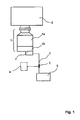
- Fig. 1 shows a vacuum arrangement according to the invention.
- a vacuum device 1 is connected.
- it is a vacuum pump 1a with flanged control electronics 1b.
- the control electronics 1b can optionally be flanged or spatially separated and connected via a cable to the vacuum pump 1a.
- the vacuum device 1 can also be a controllable valve, a measuring tube or the like.
- the vacuum device 1 has a communication module 2, which is arranged directly on the control electronics 1b in the example shown. However, it may also be separate from this, for example in an adjacent control cabinet, and then communicate with the vacuum device 1 via a cable.
- the control electronics 2 is connected via a communication line 7 to a central control device 5.
- a communication line 7 to a central control device 5.
- central control device 5 further vacuum devices (not shown) via other communication lines (also not shown) may be connected.
- a device 4 is coupled to the communication line 7.
- the device 4 acquires data that is exchanged in the communication line 7 between the vacuum device 1 and the central control device 5. The detection takes place without the Communication between the vacuum device 1 and the central control device 5 is interrupted.
- the device 4 detects the data communicated in the communication line 7 either temporarily or permanently.
- the device 4 detects the essential parameters such as speed, pressure, power, temperature, software version and the like.
- the device 4 may also send control data such as setting commands sent to the vacuum device, such as "on / off", “accelerate” and the like, namely, when the communication from the central controller 5 is absent. This may be the case if the central controller fails or is not yet connected or configured.
- the device 4 can also automatically or manually query data in the communication module 2 and, as already stated, optionally make settings. In this case, the device 4 behaves like a normal operating device. As soon as the communication with the central control device 5 starts, no active participation in the communication takes place, that is, no messages are filtered by the device 4, data contents are supplemented or changed by information, but only the data communicated in the communication line 7 are detected , observed and / or evaluated.
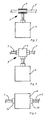
- Fig. 2 shows the communication line 7, to which the device 4 is connected by means of a coupling 3, which is designed as a non-galvanic coupling 6.
- a coupling 3 which is designed as a non-galvanic coupling 6.
- the non-galvanic coupling 6 no additional connectors are necessary.
- the connection is possible at any suitable point of the communication line 7. As a result, the greatest freedom from reaction is achieved.
- the data from the communication line 7 contactless such as inductive or capacitive detected without the bus cable 7 must be separated. It is also a connection via radio conceivable.
- Fig. 3 is the device 4 via the coupling 3, which is designed as a galvanic coupling 9, connected to the communication line 7.
- the galvanic coupling 9 means that another analog subscriber is connected to the communication line 7.
- This variant has the advantage that the coupling takes place by means of simple components.
- Fig. 4 shows a further embodiment in which the device 4 is looped by means of a 2-port coupling 10 in the communication line 7. With this embodiment, a filtering and processing of the data traffic is possible.
Landscapes
- Engineering & Computer Science (AREA)
- Mechanical Engineering (AREA)
- General Engineering & Computer Science (AREA)
- Physics & Mathematics (AREA)
- General Physics & Mathematics (AREA)
- Compressors, Vaccum Pumps And Other Relevant Systems (AREA)
Abstract
Description
- Die Erfindung betrifft eine Vakuumanordnung mit einem Vakuumgerät sowie ein Verfahren zur Erfassung von in einer Kommunikationsleitung zwischen einem Vakuumgerät und einer zentralen Steuereinrichtung kommunizierten Daten.
- Aus dem Stand der Technik (
DE 10 2006 045 024 A1 ) ist eine Vakuumanordnung mit einem Vakuumgerät bekannt, wobei das Vakuumgerät ein Kommunikationsmodul aufweist sowie ein Kontrollgerät mit einem Funkmodul. - Derartige Vakuumgeräte, die mit einer zentralen Steuereinrichtung mittels einer Kommunikationsleitung verbunden sind, weisen den Nachteil auf, dass zum Beispiel bei einer Wartung des Vakuumgerätes keine lokalen Daten abrufbar sind.
- Insbesondere bei der Inbetriebnahme oder zu Wartungszwecken ist es häufig erwünscht, eine lokale Kontrolle wesentlicher Parameter durchführen zu können. Hierzu ist es gemäß dem Stand der Technik erforderlich, die Kommunikation mit der zentralen Steuerung zu unterbrechen, um lokal ein Anzeigegerät anzuschließen.
- Das der Erfindung zugrunde liegende technische Problem besteht darin, eine Vakuumanordnung mit einem Vakuumgerät anzugeben, mit der eine lokale Kontrolle des Vakuumgerätes möglich ist. Darüber hinaus soll ein verbessertes Verfahren zur Erfassung von in einer Kommunikationsleitung zwischen einem Vakuumgerät und einer zentralen Steuereinrichtung kommunizierten Daten angegeben werden.
- Dieses technische Problem wird durch eine Vakuumanordnung mit den Merkmalen gemäß Anspruch 1 sowie durch ein Verfahren mit den Merkmalen gemäß Anspruch 17 gelöst.
- Die erfindungsgemäße Vakuumanordnung mit einem Vakuumgerät, welche eine zentrale Steuereinrichtung für das Vakuumgerät und eine Kommunikationsleitung zwischen dem Vakuumgerät und der zentralen Steuereinrichtung aufweist, zeichnet sich dadurch aus, dass in und/oder an der Kommunikationsleitung eine zusätzliche Vorrichtung zum Erfassen der in der Kommunikationsleitung kommunizierten Daten angeordnet ist.
- Unter Vakuumanordnung im Sinne der vorliegenden Erfindung wird eine Anordnung mit einem Vakuumgerät verstanden, die zusätzlich eine zentrale Steuereinrichtung für das Vakuumgerät aufweist. Zu der Vakuumanordnung gehört auch eine Kommunikationsleitung zwischen dem Vakuumgerät und der zentralen Steuereinrichtung.
- Die zusätzliche Vorrichtung, die in und/oder an der Kommunikationsleitung zum Erfassen der in der Kommunikationsleitung kommunizierten Daten angeordnet ist, erlaubt die Erfassung der lokalen Daten des entsprechenden Vakuumgerätes, so dass die wesentlichen Parameter, wie zum Beispiel Drehzahl, Druck, Leistung, Softwarestand, Temperatur und dergleichen abgefragt werden können. Diese Erfassung ist insbesondere bei der Inbetriebnahme oder zu Wartungszwecken vorteilhaft, um die lokale Kontrolle des Vakuumgerätes zu erzielen.
- Gemäß einer vorteilhaften Weiterbildung der Erfindung ist die Vorrichtung zusätzlich als eine Daten auswertende und/oder Daten anzeigende Vorrichtung ausgebildet. Hierdurch ist es möglich, die lokal erfassten Daten unmittelbar anzuzeigen, beispielsweise für die Inbetriebnahme oder Wartung des Vakuumgerätes. Eine Auswertung der Daten kann ebenfalls sinnvoll sein, damit bei der Wartung oder Inbetriebnahme Fehler leicht ermittelt werden können.
- Gemäß einer besonders bevorzugten Ausführungsform der Erfindung ist die Vorrichtung als eine die Daten während einer unterbrechungsfreien Kommunikation zwischen dem Vakuumgerät und der zentralen Steuereinrichtung erfassende Vorrichtung ausgebildet.
- Die Erfindung wird gemäß dieser Ausführungsform zeitweise oder dauerhaft in und/oder an der Kommunikationsleitung zwischen dem Vakuumgerät und der zentralen Steuerung angeordnet. Die Vorrichtung liest die vorbeikommenden Daten mit. Es kann eine Auswahl getroffen werden, welche der Daten in der Vorrichtung lokal angezeigt werden sollen.
- Der besondere Vorteil dieser Ausführungsform liegt darin, dass die Kommunikation zwischen dem Vakuumgerät und der zentralen Steuereinrichtung nicht unterbrochen wird, sondern dass diese unbeeinflusst weiter durchgeführt wird und dass die Vorrichtung gemäß der Erfindung sämtliche oder nur ausgewählte, in der Kommunikationsleitung kommunizierten Daten erfasst und nach den Wünschen des Benutzers weiter verarbeitet, das heißt auswertet und/oder anzeigt.
- Gemäß einer weiteren vorteilhaften Ausführungsform der Erfindung ist vorgesehen, dass bei ausbleibender Kommunikation zwischen der zentralen Steuereinrichtung und dem Vakuumgerät die Vorrichtung zusätzlich als eine Daten abfragende und/oder das Vakuumgerät steuernde Vorrichtung ausgebildet ist. Die Kommunikation bleibt beispielsweise aus, wenn die zentrale Steuerungseinrichtung noch nicht angeschlossen oder projektiert ist. Auch bei einem Ausfall der zentralen Steuereinrichtung bleibt die Kommunikation aus. In diesem Fall der ausbleibenden Kommunikation kann die erfindungsgemäße Vorrichtung selbst zeitweise automatisch oder manuell Daten bei dem Vakuumgerät abfragen und/oder Einstellungen an dem Vakuumgerät vornehmen. In diesem Fall verhält sich die erfindungsgemäße Vorrichtung wie ein normales Bediengerät. Sobald die Kommunikation mit der zentralen Steuerung einsetzt, was abhängig von der Topologie - in oder an der Kommunikationsleitung - durch direkten Empfang oder Beurteilung der Signalqualität erfolgen kann, erfolgt keine aktive Teilnahme mehr an der Kommunikation, das heißt, es werden von der erfindungsgemäßen Vorrichtung keine Telegramme mehr gesendet, sondern nur wie gemäß der Hauptausführungsform der Erfindung vorgesehen, die vorbeikommenden Daten beobachtet und/oder ausgewertet. Das bedeutet, dass die Vorrichtung ausschließlich bei ausbleibender Kommunikation zwischen dem Vakuumgerät und der zentralen Steuereinrichtung selbst aktiv Daten bei dem Vakuumgerät abfragt und/oder Einstellungen an dem Vakuumgerät vornimmt.
- Gemäß einer weiteren vorteilhaften Ausführungsform der Erfindung kann der Anschluss in oder an der Kommunikationsleitung galvanisch erfolgen. Hierbei erfolgt ein direkter Anschluss an die Kommunikationsleitung, wodurch einfache Komponenten verwendbar sind oder eine Filterung und Bearbeitung des Datenverkehrs möglich ist.
- Gemäß einer vorteilhaften Ausführungsform der Erfindung ist entweder ein zusätzlicher Teilnehmer (ein Anschluss) oder eine eingeschleifte Vorrichtung (zwei unabhängige Ports) vorgesehen.
- Ist der Anschluss als eingeschleifte Vorrichtung ausgebildet, wird die durchgehende Kommunikationsleitung unterbrochen und durch einen Umweg wieder geschlossen, das heißt, die Umwegleitung wird in die durchgehende Leitung eingeschleift.
- Es besteht auch die Möglichkeit, andere galvanische Anschlüsse vorzusehen.
- Gemäß einer anderen vorteilhaften Ausführungsform der Erfindung kann die Vorrichtung auch einen nicht-galvanischen Anschluss aufweisen. Bei der galvanischen Trennung liegt eine elektrische Trennung zwischen zwei leitfähigen Gegenständen, beispielsweise Stromkreisen, vor. Über entsprechende Kopplungsglieder werden zwischen den leitfähigen Gegenständen elektrische Leistungen oder Signale übertragen. In diesem Fall besteht die Möglichkeit, dass die Vorrichtung als eine die Daten der Kommunikationsleitung induktiv oder kapazitiv erfassende Vorrichtung ausgebildet ist. Hierbei ist kein direkter Anschluss an die Kommunikationsleitung erforderlich.
- Die Kommunikationsleitung kann gemäß der Erfindung als RS485 oder als Profibus ausgebildet sein. Aufgrund der symmetrischen Signalübertragung ist RS485 durch eine hohe Toleranz gegenüber elektromagnetischen Störungen gekennzeichnet. Andere Arten von Kommunikationsleitungen sind ebenfalls möglich.
- Die Vorrichtung gemäß der Erfindung kann gemäß einer weiteren Ausführungsform der Erfindung als eine die kommunizierten Daten ändernde Vorrichtung ausgebildet sein. Die Vorrichtung kann also bei geeigneter Anschaltung auch die laufende Kommunikation beeinflussen, zum Beispiel Telegramme filtern, Dateninhalte um Informationen ergänzen oder ändern.
- Gemäß einer weiteren vorteilhaften Ausführungsform kann die Vorrichtung auch den Datenverkehr und/oder die Daten aufzeichnen. Hierdurch ist die Protokollierung möglicher Fehler durchführbar.
- Vorteilhaft weist die Vorrichtung Bedienelemente und/oder eine optische Anzeigevorrichtung und/oder eine akustische Anzeigevorrichtung auf. Im einfachsten Fall können Indikatoren, zum Beispiel LED's zur Anzeige von Daten oder Betriebszuständen vorgesehen sein. Zusätzlich können Bedienelemente wie Taster oder Schalter vorgesehen sein, um beispielsweise einen Betriebsmodus oder die anzuzeigenden Daten zu wählen. Darüber hinaus können auch Displays zur Anzeige von Zeichen oder Grafiken Verwendung finden bis hin zum reinen Betriebsmodus in üblichen Bedien- und Anzeigegeräten. Es ist auch möglich, gemäß einer weiteren Ausführungsform der Erfindung, akustische Signale vorzusehen, zum Beispiel zur Warnung bei Überschreitung voreingestellter Werte.
- Gemäß einer besonders bevorzugten Ausführungsform der Erfindung ist das Vakuumgerät als Vakuumpumpe oder als Vakuummessmittel, beispielsweise als Messröhre, ausgebildet. Insbesondere bei diesen Geräten ist der Einsatz einer eine Kommunikation zwischen zentraler Steuereinrichtung und Vakuumgerät nicht unterbrechenden Vorrichtung von Vorteil.
- Das erfindungsgemäße Verfahren zur Erfassung von in einer Kommunikationsleitung zwischen einem Vakuumgerät und einer zentralen Steuereinrichtung kommunizierten Daten zeichnet sich dadurch aus, dass die Daten ohne Unterbrechung der Kommunikation zwischen dem Datengerät und der zentralen Steuereinrichtung von einer Vorrichtung erfasst werden.
- Das erfindungsgemäße Verfahren weist den Vorteil auf, dass die Kommunikation zwischen der zentralen Steuereinrichtung und dem Vakuumgerät ungehindert weiter fortgeführt werden kann und trotzdem die Daten ohne Unterbrechung der Kommunikation lokal erfasst werden. Diese Daten können zum Beispiel zusätzlich ausgewertet oder angezeigt werden. Dieses Verfahren ist insbesondere bei der Inbetriebnahme oder Wartung eines Vakuumgerätes vorteilhaft einsetzbar, da in diesem Fall lediglich die erforderlichen, das heißt gewünschten Daten, die ohnehin zwischen der zentralen Steuerungseinrichtung und dem Vakuumgerät mittels der Kommunikationsleitung kommuniziert werden, von der Vorrichtung erfasst und bei Bedarf angezeigt oder ausgewertet werden.
- Damit ist es möglich, ein Vakuumgerät lokal in Betrieb zu nehmen oder zu warten.
- Sollte die Kommunikation zwischen Vakuumgerät und der zentralen Steuereinrichtung ausbleiben, ist es möglich, dass die Vorrichtung ausschließlich bei ausbleibender Kommunikation automatisch oder manuell Daten des Vakuumgerätes abfragt und/oder das Vakuumgerät steuert. Die Kommunikation kann ausbleiben, wenn eine zentrale Steuereinrichtung noch nicht angeschlossen oder projektiert ist, oder wenn die zentrale Steuereinrichtung einen Fehler aufweist. In diesem Fall ist es möglich, dass die Vorrichtung Aufgaben der zentralen Steuereinrichtung übernimmt, um das Vakuumgerät zu steuern.
- Gemäß einer vorteilhaften Ausführungsform der Erfindung werden die Daten über einen galvanischen Anschluss an der Kommunikationsleitung erfasst. Der galvanische Anschluss kann beispielsweise als zusätzlicher Teilnehmer ausgebildet sein, das heißt, es ist ein Anschluss in der Kommunikationsleitung vorgesehen. Bei dieser Ausführung sind einfache Komponenten verwendbar. Es kann auch ein Anschluss vorgesehen sein, der als eine eingeschleifte Vorrichtung mit zwei unabhängigen Ports ausgebildet ist. Durch diese Art des Anschlusses ist die Filterung und Bearbeitung des Datenverkehrs möglich.
- Es ist auch möglich, die Daten über einen nicht-galvanischen Anschluss zu erfassen. Das bedeutet, dass eine galvanische Trennung zwischen der Erfassungsvorrichtung und der Kommunikationsleitung vorliegt. Diese Ausführungsform weist den Vorteil auf, dass keine zusätzlichen Steckverbinder notwendig sind. Die Ankopplung ist an jeder geeigneten Stelle ohne Eingriff in die Kommunikationsleitung möglich und es ist darüber hinaus die größte Rückwirkungsfreiheit erzielbar. In diesem Fall werden die Daten der Kommunikationsleitung beispielsweise induktiv oder kapazitiv erfasst.
- Diese Erfassungsarten haben sich als vorteilhaft wegen der zuverlässigen Arbeitsweise herausgestellt.
- Als Kommunikationsleitung wird vorzugsweise ein RS485-Standard oder ein Profibus verwendet. Andere Arten der Kommunikationsleitung sind gemäß der Erfindung auch möglich.
- Gemäß einer weiteren vorteilhaften Ausführungsform der Erfindung kann die Vorrichtung die kommunizierten Daten während der Kommunikation zwischen dem Vakuumgerät und der zentralen Steuereinrichtung verändern. Bei geeigneter Anschaltung der Vorrichtung kann die Vorrichtung die laufende Kommunikation beeinflussen, zum Beispiel Telegramme filtern, Dateninhalte um Informationen ergänzen oder ändern. Eine Aufzeichnung des Datenverkehrs und/oder der Daten ist ebenfalls denkbar und vorteilhaft, um die Abläufe über einen kürzeren oder längeren Zeitraum zu protokollieren.
- Eine weitere vorteilhafte Ausführungsform der Erfindung sieht vor, dass als Vakuumgerät eine Vakuumpumpe oder ein Vakuummessmittel, beispielsweise eine Messröhre verwendet wird. Das erfindungsgemäße Verfahren ist bei diesen Geräten besonders vorteilhaft einsetzbar.
- Die erfindungsgemäße Vakuumanordnung wie auch das erfindungsgemäße Verfahren ist auf Vakuumanwendungen beschränkt. Das Verfahren und die Vakuumanordnung weisen den Vorteil gegenüber dem Stand der Technik auf, dass sie kompakte und günstige Bauformen zum vorteilhaften Einsatz bei Inbetriebnahme und bei dem Betrieb von Vakuumanlagen und Vakuumanwendungen möglich machen.
- Die Vakuumanordnung mit einem Vakuumgerät und der Vorrichtung zum Erfassen der in der Kommunikationsleitung kommunizierten Daten kann, wie schon ausgeführt, eine Anzeige aufweisen. Diese Anzeige kann beispielsweise in Form von Indikatoren, zeichenbasierten, grafischen oder gemischten Displays, als akustische Geber, als digitale oder analoge Ausgänge und/oder als Relais ausgebildet sein.
- Die Einflussnahme der erfindungsgemäßen Vakuumanordnung auf die Anzeige oder die Bedienung kann beispielsweise durch automatisches Durchrollen aller relevanten Werte durch eine manuelle Auswahl durch Tasten und/oder durch Änderung der Betriebsart ausgebildet sein.
- Die erfindungsgemäße Vakuumanordnung wie auch das erfindungsgemäße Verfahren erlauben eine lokale und rückwirkungsfreie Erfassung von Daten in Vakuumanlagen, das heißt in Vakuumanordnungen mit einem Vakuumgerät. Diese lokal und rückwirkungsfrei erfassten Daten können ebenfalls lokal und rückwirkungsfrei ausgewertet und angezeigt werden.
- Weitere Merkmale und Vorteile der Erfindung ergeben sich anhand der zugehörigen Zeichnung, in der mehrere Ausführungsbeispiele einer erfindungsgemäßen Vakuumanordnung nur beispielhaft dargestellt sind. In der Zeichnung zeigen:
- Fig. 1
- eine schematische Darstellung einer erfindungsgemäßen Vakuumanordnung;
- Fig. 2
- eine schematische Darstellung einer nicht-galvanischen Ankopplung an die Kommunikationsleitung;
- Fig. 3
- eine schematische Darstellung einer galvanischen Ankopplung an einer Kommunikationsleitung;
- Fig. 4
- eine schematische Darstellung einer 2-Port-Ankopplung.
-
Fig. 1 zeigt eine erfindungsgemäße Vakuumanordnung. An einem Rezipienten 8 ist ein Vakuumgerät 1 angeschlossen. Im gezeigten Beispiel handelt es sich um eine Vakuumpumpe 1a mit angeflanschter Steuerelektronik 1b. Die Steuerelektronik 1b kann wahlweise angeflanscht oder räumlich getrennt und über ein Kabel mit der Vakuumpumpe 1a verbunden sein. Es kann sich bei dem Vakuumgerät 1 auch um ein steuerbares Ventil, eine Messröhre oder dergleichen handeln. Das Vakuumgerät 1 weist ein Kommunikationsmodul 2 auf, welches im gezeigten Beispiel direkt an der Steuerelektronik 1b angeordnet ist. Es kann jedoch auch getrennt von diesem sein, beispielsweise in einem benachbarten Schaltschrank, und dann über ein Kabel mit dem Vakuumgerät 1 in Verbindung stehen. - Die Steuerelektronik 2 ist über eine Kommunikationsleitung 7 mit einer zentralen Steuereinrichtung 5 verbunden. An der zentralen Steuereinrichtung 5 können weitere Vakuumgeräte (nicht dargestellt) über weitere Kommunikationsleitungen (ebenfalls nicht darstellt) verbunden sein.
- Über einen Anschluss 3 ist eine Vorrichtung 4 an der Kommunikationsleitung 7 angekoppelt. Die Vorrichtung 4 erfasst Daten, die in der Kommunikationsleitung 7 zwischen dem Vakuumgerät 1 und der zentralen Steuereinrichtung 5 ausgetauscht werden. Die Erfassung erfolgt, ohne dass die Kommunikation zwischen dem Vakuumgerät 1 und der zentralen Steuereinrichtung 5 unterbrochen wird.
- Die Vorrichtung 4 erfasst die in der Kommunikationsleitung 7 kommunizierten Daten entweder zeitweise oder dauerhaft. Die Vorrichtung 4 erfasst hierzu die wesentlichen Parameter wie Drehzahl, Druck, Leistung, Temperatur, Softwarestand und dergleichen. Die Vorrichtung 4 kann auch Steuerdaten wie beispielsweise Stellbefehle, die an das Vakuumgerät gesendet werden, beispielsweise "An/Aus", "Beschleunigen" und dergleichen versenden, nämlich wenn die Kommunikation von der zentralen Steuerung 5 ausbleibt. Dies kann der Fall sein, wenn die zentrale Steuerung ausfällt oder noch nicht angeschlossen oder projektiert ist.
- In diesem Fall kann die Vorrichtung 4 auch automatisch oder manuell Daten bei dem Kommunikationsmodul 2 abfragen und wie schon ausgeführt, gegebenenfalls Einstellungen vornehmen. In diesem Falle verhält sich die Vorrichtung 4 wie ein normales Bediengerät. Sobald die Kommunikation mit der zentralen Steuereinrichtung 5 einsetzt, erfolgt keine aktive Teilnahme mehr an der Kommunikation, das heißt, es werden durch die Vorrichtung 4 keine Telegramme gefiltert, Dateninhalte um Informationen ergänzt oder geändert, sondern nur die in der Kommunikationsleitung 7 kommunizierten Daten werden erfasst, beobachtet und/oder ausgewertet.
- Durch diese erfindungsgemäße Vakuumanordnung ist eine lokale Überwachung der Vakuumpumpe 1 zeitweise oder dauerhaft ohne Rückwirkung auf die Kommunikation zwischen dem Vakuumgerät 1 und der zentralen Steuereinrichtung 5 möglich. Dies ist besonders vorteilhaft bei der Inbetriebnahme und der Wartung von Vakuumanlagen.
-
Fig. 2 zeigt die Kommunikationsleitung 7, an der die Vorrichtung 4 mittels einer Ankopplung 3, die als nicht-galvanische Ankopplung 6 ausgebildet ist, angeschlossen ist. Bei der nicht-galvanischen Ankopplung 6 sind keine zusätzlichen Steckverbinder notwendig. Die Anschaltung ist an jeder geeigneten Stelle der Kommunikationsleitung 7 möglich. Hierdurch wird die größte Rückwirkungsfreiheit erzielt. - Bei der nicht-galvanischen Ankopplung werden die Daten aus der Kommunikationsleitung 7 kontaktlos, wie zum Beispiel induktiv oder kapazitiv erfasst, ohne dass das Buskabel 7 aufgetrennt werden muss. Es ist auch eine Anbindung per Funk denkbar.
- Gemäß
Fig. 3 ist die Vorrichtung 4 über die Ankopplung 3, die als galvanische Ankopplung 9 ausgebildet ist, an der Kommunikationsleitung 7 angeschlossen. Die galvanische Ankopplung 9 bedeutet, dass analog ein weiterer Teilnehmer an der Kommunikationsleitung 7 angeschlossen ist. Diese Variante weist den Vorteil auf, dass die Ankopplung mittels einfacher Komponenten erfolgt. -
Fig. 4 zeigt ein weiteres Ausführungsbeispiel, bei dem die Vorrichtung 4 mittels einer 2-Port-Ankopplung 10 in der Kommunikationsleitung 7 eingeschleift ist. Mit diesem Ausführungsbeispiel ist eine Filterung und Bearbeitung des Datenverkehrs möglich. -
- 1
- Vakuumgerät
- 1a
- Vakuumpumpe
- 1b
- Steuerelektronik
- 2
- Kommunikationsmodul
- 3
- Ankopplung
- 4
- Vorrichtung
- 5
- zentrale Steuereinrichtung
- 6
- nicht-galvanische Ankopplung
- 7
- Kommunikationsleitung
- 8
- Rezipient
- 9
- galvanische Ankopplung
- 10
- 2-Port-Ankopplung
Claims (28)
- Vakuumanordnung mit einem Vakuumgerät, welche eine zentrale Steuereinrichtung für das Vakuumgerät und eine Kommunikationsleitung zwischen dem Vakuumgerät und der zentralen Steuereinrichtung aufweist,
dadurch gekennzeichnet, dass in und/oder an der Kommunikationsleitung (7) eine zusätzliche Vorrichtung (4) zum Erfassen der in der Kommunikationsleitung (7) kommunizierten Daten angeordnet ist. - Vakuumanordnung nach Anspruch 1, dadurch gekennzeichnet, dass die Vorrichtung (4) als eine Daten auswertende und/oder anzeigende Vorrichtung (4) ausgebildet ist.
- Vakuumanordnung nach Anspruch 1 oder 2, dadurch gekennzeichnet, dass die Vorrichtung (4) als eine die Daten während einer unterbrechungsfreien Kommunikation zwischen dem Vakuumgerät (1) und der zentralen Steuereinrichtung (5) erfassende Vorrichtung (4) ausgebildet ist.
- Vakuumanordnung nach einem der vorhergehenden Ansprüche, dadurch gekennzeichnet, dass bei ausbleibender Kommunikation zwischen der zentralen Steuereinrichtung (5) und dem Vakuumgerät (1) die Vorrichtung (4) zusätzlich als eine Daten abfragende und/oder das Vakuumgerät (1) steuernde Vorrichtung (4) ausgebildet ist.
- Vakuumanordnung nach einem der vorhergehenden Ansprüche, dadurch gekennzeichnet, dass die Vorrichtung (4) einen galvanischen Anschluss (9) an die Kommunikationsleitung (7) aufweist.
- Vakuumanordnung nach Anspruch 5, dadurch gekennzeichnet, dass der Anschluss (9) als zusätzlicher Teilnehmer ausgebildet ist.
- Vakuumanordnung nach Anspruch 5, dadurch gekennzeichnet, dass der Anschluss (10) als eingeschleifte Vorrichtung (4) mit zwei unabhängigen Ports ausgebildet ist.
- Vakuumanordnung nach einem der Ansprüche 1 bis 4, dadurch gekennzeichnet, dass die Vorrichtung (4) einen nicht-galvanischen Anschluss (6) aufweist.
- Vakuumanordnung nach Anspruch 8, dadurch gekennzeichnet, dass die Vorrichtung (4) als eine die Daten der Kommunikationsleitung (7) induktiv oder kapazitiv erfassende Vorrichtung (4) ausgebildet ist.
- Vakuumanordnung nach einem der vorhergehenden Ansprüche, dadurch gekennzeichnet, dass die Kommunikationsleitung (7) als RS485 oder als Profibus ausgebildet ist.
- Vakuumanordnung nach einem der vorhergehenden Ansprüche, dadurch gekennzeichnet, dass die Vorrichtung (4) als eine die kommunizierten Daten ändernde Vorrichtung (4) ausgebildet ist.
- Vakuumanordnung nach einem der vorhergehenden Ansprüche, dadurch gekennzeichnet, dass die Vorrichtung (4) als eine die Daten und/oder einen Datenverkehr aufzeichnende Vorrichtung (4) ausgebildet ist.
- Vakuumanordnung nach einem der vorhergehenden Ansprüche, dadurch gekennzeichnet, dass die Vorrichtung (4) Bedienelemente und/oder eine optische Anzeigevorrichtung und/oder eine akustische Anzeigevorrichtung aufweist.
- Vakuumanordnung nach Anspruch 13, dadurch gekennzeichnet, dass die Bedienelemente als Taster oder Schalter ausgebildet sind.
- Vakuumanordnung nach Anspruch 13, dadurch gekennzeichnet, dass die optische Anzeige als Indikatoren oder als wenigstens ein Display ausgebildet ist.
- Vakuumanordnung nach einem der vorhergehenden Ansprüche, dadurch gekennzeichnet, dass das Vakuumgerät (1) als Vakuumpumpe oder als Vakuummessmittel ausgebildet ist.
- Verfahren zur Erfassung von in einer Kommunikationsleitung zwischen einem Vakuumgerät und einer zentralen Steuereinrichtung kommunizierten Daten,
dadurch gekennzeichnet, dass die Daten ohne Unterbrechung der Kommunikation zwischen dem Vakuumgerät (1) und der zentralen Steuereinrichtung (5) von einer Vorrichtung (4) erfasst werden. - Verfahren nach Anspruch 17, dadurch gekennzeichnet, dass die Vorrichtung (4) zusätzlich zur Erfassung der Daten die Daten auswertet und/oder anzeigt.
- Verfahren nach einem der Ansprüche 17 oder 18, dadurch gekennzeichnet, dass die Vorrichtung (4) ausschließlich bei ausbleibender Kommunikation zwischen Vakuumgerät (1) und der zentralen Steuereinrichtung (5) automatisch oder manuell Daten des Vakuumgerätes (1) abfragt und/oder das Vakuumgerät (1) steuert.
- Verfahren nach einem der Ansprüche 17 bis 19, dadurch gekennzeichnet, dass die Daten über einen galvanischen Anschluss (9) an der Kommunikationsleitung (7) von der Vorrichtung (4) erfasst werden.
- Verfahren nach Anspruch 20, dadurch gekennzeichnet, dass die Daten über einen zusätzlichen Teilnehmer (9) erfasst werden.
- Verfahren nach Anspruch 20, dadurch gekennzeichnet, dass die Daten über eine eingeschleifte Vorrichtung mit zwei unabhängigen Ports (10) erfasst werden.
- Verfahren nach einem der Ansprüche 17 bis 19, dadurch gekennzeichnet, dass die Daten über einen nicht-galvanischen Anschluss (6) erfasst werden.
- Verfahren nach Anspruch 23, dadurch gekennzeichnet, dass die Daten der Kommunikationsleitung (7) induktiv oder kapazitiv erfasst werden.
- Verfahren nach einem der Ansprüche 17 bis 24, dadurch gekennzeichnet, dass als Kommunikationsleitung (7) ein RS485 oder ein Profibus verwendet wird.
- Verfahren nach einem der Ansprüche 17 bis 25, dadurch gekennzeichnet, dass die Vorrichtung (4) die kommunizierten Daten während der Kommunikation zwischen dem Vakuumgerät (1) und der zentralen Steuereinrichtung (5) verändert.
- Verfahren nach einem der Ansprüche 17 bis 26, dadurch gekennzeichnet, dass die Vorrichtung (4) die kommunizierten Daten und/oder den Datenverkehr aufzeichnet.
- Verfahren nach einem der Ansprüche 17 bis 27, dadurch gekennzeichnet, dass als Vakuumgerät (1) eine Vakuumpumpe oder ein Vakuummessmittel verwendet wird.
Applications Claiming Priority (1)
| Application Number | Priority Date | Filing Date | Title |
|---|---|---|---|
| DE102013106474.4A DE102013106474B4 (de) | 2013-06-20 | 2013-06-20 | Anordnung mit einem Vakuumgerät sowie Verfahren zur Erfassung von in einer Kommunikationsleitung zwischen einem Vakuumgerät und einer zentralen Steuereinrichtung kommunizierten Daten |
Publications (2)
| Publication Number | Publication Date |
|---|---|
| EP2827314A1 true EP2827314A1 (de) | 2015-01-21 |
| EP2827314B1 EP2827314B1 (de) | 2017-09-27 |
Family
ID=50771201
Family Applications (1)
| Application Number | Title | Priority Date | Filing Date |
|---|---|---|---|
| EP14169692.2A Active EP2827314B1 (de) | 2013-06-20 | 2014-05-23 | Vakuumanordnung mit einem vakuumgerät sowie verfahren zur erfassung von in einer kommunikationsleitung zwischen einem vakuumgerät und einer zentralen steuereinrichtung kommunizierten daten |
Country Status (2)
| Country | Link |
|---|---|
| EP (1) | EP2827314B1 (de) |
| DE (1) | DE102013106474B4 (de) |
Families Citing this family (1)
| Publication number | Priority date | Publication date | Assignee | Title |
|---|---|---|---|---|
| US12520452B2 (en) | 2022-05-04 | 2026-01-06 | Hoffman Enclosures Inc. | Replaceable pump unit for cooling systems |
Citations (4)
| Publication number | Priority date | Publication date | Assignee | Title |
|---|---|---|---|---|
| US20030014160A1 (en) * | 2001-07-13 | 2003-01-16 | Helix Technology Corporation | Vacuum system central control information server |
| EP1903530A2 (de) * | 2006-09-23 | 2008-03-26 | Pfeiffer Vacuum GmbH | Anordnung mit Vakuumgerät und Verfahren zu deren Betrieb |
| DE102006045024A1 (de) | 2006-09-23 | 2008-03-27 | Pfeiffer Vacuum Gmbh | Anordnung mit Vakuumgerät |
| US20100083731A1 (en) * | 2008-10-06 | 2010-04-08 | Rosemount Inc. | Pressure-based diagnostic system for process transmitter |
Family Cites Families (8)
| Publication number | Priority date | Publication date | Assignee | Title |
|---|---|---|---|---|
| DE19815097C2 (de) * | 1998-04-03 | 2002-03-14 | Siemens Ag | Busmasterumschalteinheit |
| DE10032774A1 (de) * | 2000-07-06 | 2002-01-17 | Endress Hauser Gmbh Co | Feldgerät |
| DE10252277A1 (de) * | 2002-11-11 | 2004-05-27 | Abb Patent Gmbh | Verfahren zur Bedienung von Feldgeräten |
| US20080123522A1 (en) * | 2006-07-28 | 2008-05-29 | David Charles Elliott | Redundancy coupler for industrial communications networks |
| DE102007032715B4 (de) * | 2007-07-13 | 2009-04-09 | Abb Ag | System und Verfahren zur Überwachung des Datenverkehrs bei einem Feldbus |
| DE102008061435A1 (de) * | 2008-12-10 | 2010-06-17 | Pfeiffer Vacuum Gmbh | Mit einer Vakuumpumpe verbindbares Gerät |
| DE102010048286B4 (de) | 2010-10-14 | 2013-08-01 | Kruno Pranjic | Untertagedatenübertragungsnetz mit Diagnosegerät |
| EP2466405A1 (de) * | 2010-12-15 | 2012-06-20 | Siemens Aktiengesellschaft | Steuerungssystem für eine industrielle Einrichtung mit wahlfreier Umschaltung auf verschiedene Zentraleinheiten |
-
2013
- 2013-06-20 DE DE102013106474.4A patent/DE102013106474B4/de active Active
-
2014
- 2014-05-23 EP EP14169692.2A patent/EP2827314B1/de active Active
Patent Citations (4)
| Publication number | Priority date | Publication date | Assignee | Title |
|---|---|---|---|---|
| US20030014160A1 (en) * | 2001-07-13 | 2003-01-16 | Helix Technology Corporation | Vacuum system central control information server |
| EP1903530A2 (de) * | 2006-09-23 | 2008-03-26 | Pfeiffer Vacuum GmbH | Anordnung mit Vakuumgerät und Verfahren zu deren Betrieb |
| DE102006045024A1 (de) | 2006-09-23 | 2008-03-27 | Pfeiffer Vacuum Gmbh | Anordnung mit Vakuumgerät |
| US20100083731A1 (en) * | 2008-10-06 | 2010-04-08 | Rosemount Inc. | Pressure-based diagnostic system for process transmitter |
Also Published As
| Publication number | Publication date |
|---|---|
| EP2827314B1 (de) | 2017-09-27 |
| DE102013106474B4 (de) | 2024-10-10 |
| DE102013106474A1 (de) | 2014-12-24 |
Similar Documents
| Publication | Publication Date | Title |
|---|---|---|
| EP2984530B1 (de) | Messumformerspeisegerät mit abschaltbarer funkschnittstelle | |
| DE102013111714B4 (de) | Verfahren zur Funktionseinstellung einer Messstelle | |
| DE102008014448B4 (de) | Intelligente Enddruckwächtereinheit | |
| DE102007032715A1 (de) | System und Verfahren zur Überwachung des Datenverkehrs bei einem Feldbus | |
| EP2016470A1 (de) | Bediengerät zum informationsaustausch mit einem feldgerät in einem automatisierungssystem | |
| DE102013204535A1 (de) | Busteilnehmer für einen Feldbus der Automatisierungstechnik | |
| DE102017123821A1 (de) | Anzeige- und/oder Bedienmodul | |
| EP3283928B1 (de) | Verfahren zum automatischen hinzu- oder wegschalten eines kommunikationswiderstandes eines hart-gerätes | |
| EP3526928A1 (de) | Verfahren zur datenübertragung zwischen einem feldgerät der automatisierungstechnik und einer kommunikationsbox | |
| EP3647600B1 (de) | Erkennung eines elektrisch angeschlossenen zubehörs | |
| EP0658831B1 (de) | Rechnergestütztes Entwurfsverfahren für ein programmierbares Automatisierungssystem | |
| DE10158745A1 (de) | Anordnung mit einem Messumformer und mindestens einem Messwertgeber, die gemeinsam über einen Feldbus mit einer Prozesssteuerung verbunden sind | |
| DE102014105292B4 (de) | Vorrichtung und System zum Bedienen eines Feldgerätes | |
| EP2827314B1 (de) | Vakuumanordnung mit einem vakuumgerät sowie verfahren zur erfassung von in einer kommunikationsleitung zwischen einem vakuumgerät und einer zentralen steuereinrichtung kommunizierten daten | |
| DE102018131685A1 (de) | Feldgeräteadapter zur drahtlosen Datenübertragung | |
| DE102018118872A1 (de) | Verfahren zur Überprüfung der Datenübertragung eines elektronischen Schaltgerätes | |
| WO2014154471A1 (de) | Messgerät mit einer schnittstelle | |
| EP1079291B1 (de) | Messwertanzeigeeinheit | |
| DE102008037195A1 (de) | Vorrichtung zum Bedienen eines Feldgeräts, das in ein Funknetzwerk der Automatisierungstechnik eingebunden ist | |
| DE10164677C1 (de) | Druckluftwartungseinrichtung | |
| DE10164667C1 (de) | Druckluftwartungseinrichtung | |
| DE102014003029B4 (de) | Antriebssteuerungseinheits-Set, Verwendung einer Bedieneinheit und Verfahren zur Bedienung einer Antriebssteuerungseinheit | |
| EP3153938B1 (de) | Messanordnung | |
| EP3970345B1 (de) | Konfigurationsfreie ausgabe von in ethernet-telegrammen enthaltenen nutzdaten | |
| DE102021132838A1 (de) | Feldgerät der Automatisierungstechnik |
Legal Events
| Date | Code | Title | Description |
|---|---|---|---|
| 17P | Request for examination filed |
Effective date: 20140523 |
|
| AK | Designated contracting states |
Kind code of ref document: A1 Designated state(s): AL AT BE BG CH CY CZ DE DK EE ES FI FR GB GR HR HU IE IS IT LI LT LU LV MC MK MT NL NO PL PT RO RS SE SI SK SM TR |
|
| AX | Request for extension of the european patent |
Extension state: BA ME |
|
| PUAI | Public reference made under article 153(3) epc to a published international application that has entered the european phase |
Free format text: ORIGINAL CODE: 0009012 |
|
| R17P | Request for examination filed (corrected) |
Effective date: 20150701 |
|
| RBV | Designated contracting states (corrected) |
Designated state(s): AL AT BE BG CH CY CZ DE DK EE ES FI FR GB GR HR HU IE IS IT LI LT LU LV MC MK MT NL NO PL PT RO RS SE SI SK SM TR |
|
| GRAP | Despatch of communication of intention to grant a patent |
Free format text: ORIGINAL CODE: EPIDOSNIGR1 |
|
| INTG | Intention to grant announced |
Effective date: 20170421 |
|
| GRAS | Grant fee paid |
Free format text: ORIGINAL CODE: EPIDOSNIGR3 |
|
| GRAA | (expected) grant |
Free format text: ORIGINAL CODE: 0009210 |
|
| AK | Designated contracting states |
Kind code of ref document: B1 Designated state(s): AL AT BE BG CH CY CZ DE DK EE ES FI FR GB GR HR HU IE IS IT LI LT LU LV MC MK MT NL NO PL PT RO RS SE SI SK SM TR |
|
| REG | Reference to a national code |
Ref country code: GB Ref legal event code: FG4D Free format text: NOT ENGLISH |
|
| REG | Reference to a national code |
Ref country code: CH Ref legal event code: EP |
|
| REG | Reference to a national code |
Ref country code: AT Ref legal event code: REF Ref document number: 932663 Country of ref document: AT Kind code of ref document: T Effective date: 20171015 |
|
| REG | Reference to a national code |
Ref country code: IE Ref legal event code: FG4D Free format text: LANGUAGE OF EP DOCUMENT: GERMAN |
|
| REG | Reference to a national code |
Ref country code: DE Ref legal event code: R096 Ref document number: 502014005568 Country of ref document: DE |
|
| PG25 | Lapsed in a contracting state [announced via postgrant information from national office to epo] |
Ref country code: NO Free format text: LAPSE BECAUSE OF FAILURE TO SUBMIT A TRANSLATION OF THE DESCRIPTION OR TO PAY THE FEE WITHIN THE PRESCRIBED TIME-LIMIT Effective date: 20171227 Ref country code: HR Free format text: LAPSE BECAUSE OF FAILURE TO SUBMIT A TRANSLATION OF THE DESCRIPTION OR TO PAY THE FEE WITHIN THE PRESCRIBED TIME-LIMIT Effective date: 20170927 Ref country code: FI Free format text: LAPSE BECAUSE OF FAILURE TO SUBMIT A TRANSLATION OF THE DESCRIPTION OR TO PAY THE FEE WITHIN THE PRESCRIBED TIME-LIMIT Effective date: 20170927 Ref country code: LT Free format text: LAPSE BECAUSE OF FAILURE TO SUBMIT A TRANSLATION OF THE DESCRIPTION OR TO PAY THE FEE WITHIN THE PRESCRIBED TIME-LIMIT Effective date: 20170927 Ref country code: SE Free format text: LAPSE BECAUSE OF FAILURE TO SUBMIT A TRANSLATION OF THE DESCRIPTION OR TO PAY THE FEE WITHIN THE PRESCRIBED TIME-LIMIT Effective date: 20170927 |
|
| REG | Reference to a national code |
Ref country code: NL Ref legal event code: MP Effective date: 20170927 |
|
| REG | Reference to a national code |
Ref country code: LT Ref legal event code: MG4D |
|
| PG25 | Lapsed in a contracting state [announced via postgrant information from national office to epo] |
Ref country code: LV Free format text: LAPSE BECAUSE OF FAILURE TO SUBMIT A TRANSLATION OF THE DESCRIPTION OR TO PAY THE FEE WITHIN THE PRESCRIBED TIME-LIMIT Effective date: 20170927 Ref country code: BG Free format text: LAPSE BECAUSE OF FAILURE TO SUBMIT A TRANSLATION OF THE DESCRIPTION OR TO PAY THE FEE WITHIN THE PRESCRIBED TIME-LIMIT Effective date: 20171227 Ref country code: GR Free format text: LAPSE BECAUSE OF FAILURE TO SUBMIT A TRANSLATION OF THE DESCRIPTION OR TO PAY THE FEE WITHIN THE PRESCRIBED TIME-LIMIT Effective date: 20171228 Ref country code: RS Free format text: LAPSE BECAUSE OF FAILURE TO SUBMIT A TRANSLATION OF THE DESCRIPTION OR TO PAY THE FEE WITHIN THE PRESCRIBED TIME-LIMIT Effective date: 20170927 |
|
| PG25 | Lapsed in a contracting state [announced via postgrant information from national office to epo] |
Ref country code: NL Free format text: LAPSE BECAUSE OF FAILURE TO SUBMIT A TRANSLATION OF THE DESCRIPTION OR TO PAY THE FEE WITHIN THE PRESCRIBED TIME-LIMIT Effective date: 20170927 |
|
| PG25 | Lapsed in a contracting state [announced via postgrant information from national office to epo] |
Ref country code: RO Free format text: LAPSE BECAUSE OF FAILURE TO SUBMIT A TRANSLATION OF THE DESCRIPTION OR TO PAY THE FEE WITHIN THE PRESCRIBED TIME-LIMIT Effective date: 20170927 Ref country code: ES Free format text: LAPSE BECAUSE OF FAILURE TO SUBMIT A TRANSLATION OF THE DESCRIPTION OR TO PAY THE FEE WITHIN THE PRESCRIBED TIME-LIMIT Effective date: 20170927 |
|
| REG | Reference to a national code |
Ref country code: FR Ref legal event code: PLFP Year of fee payment: 5 |
|
| PG25 | Lapsed in a contracting state [announced via postgrant information from national office to epo] |
Ref country code: EE Free format text: LAPSE BECAUSE OF FAILURE TO SUBMIT A TRANSLATION OF THE DESCRIPTION OR TO PAY THE FEE WITHIN THE PRESCRIBED TIME-LIMIT Effective date: 20170927 Ref country code: SK Free format text: LAPSE BECAUSE OF FAILURE TO SUBMIT A TRANSLATION OF THE DESCRIPTION OR TO PAY THE FEE WITHIN THE PRESCRIBED TIME-LIMIT Effective date: 20170927 Ref country code: SM Free format text: LAPSE BECAUSE OF FAILURE TO SUBMIT A TRANSLATION OF THE DESCRIPTION OR TO PAY THE FEE WITHIN THE PRESCRIBED TIME-LIMIT Effective date: 20170927 Ref country code: IS Free format text: LAPSE BECAUSE OF FAILURE TO SUBMIT A TRANSLATION OF THE DESCRIPTION OR TO PAY THE FEE WITHIN THE PRESCRIBED TIME-LIMIT Effective date: 20180127 |
|
| REG | Reference to a national code |
Ref country code: DE Ref legal event code: R097 Ref document number: 502014005568 Country of ref document: DE |
|
| PG25 | Lapsed in a contracting state [announced via postgrant information from national office to epo] |
Ref country code: DK Free format text: LAPSE BECAUSE OF FAILURE TO SUBMIT A TRANSLATION OF THE DESCRIPTION OR TO PAY THE FEE WITHIN THE PRESCRIBED TIME-LIMIT Effective date: 20170927 |
|
| PLBE | No opposition filed within time limit |
Free format text: ORIGINAL CODE: 0009261 |
|
| STAA | Information on the status of an ep patent application or granted ep patent |
Free format text: STATUS: NO OPPOSITION FILED WITHIN TIME LIMIT |
|
| PG25 | Lapsed in a contracting state [announced via postgrant information from national office to epo] |
Ref country code: PL Free format text: LAPSE BECAUSE OF FAILURE TO SUBMIT A TRANSLATION OF THE DESCRIPTION OR TO PAY THE FEE WITHIN THE PRESCRIBED TIME-LIMIT Effective date: 20170927 |
|
| 26N | No opposition filed |
Effective date: 20180628 |
|
| PG25 | Lapsed in a contracting state [announced via postgrant information from national office to epo] |
Ref country code: MT Free format text: LAPSE BECAUSE OF FAILURE TO SUBMIT A TRANSLATION OF THE DESCRIPTION OR TO PAY THE FEE WITHIN THE PRESCRIBED TIME-LIMIT Effective date: 20170927 |
|
| PG25 | Lapsed in a contracting state [announced via postgrant information from national office to epo] |
Ref country code: SI Free format text: LAPSE BECAUSE OF FAILURE TO SUBMIT A TRANSLATION OF THE DESCRIPTION OR TO PAY THE FEE WITHIN THE PRESCRIBED TIME-LIMIT Effective date: 20170927 |
|
| REG | Reference to a national code |
Ref country code: CH Ref legal event code: PL |
|
| REG | Reference to a national code |
Ref country code: BE Ref legal event code: MM Effective date: 20180531 |
|
| PG25 | Lapsed in a contracting state [announced via postgrant information from national office to epo] |
Ref country code: MC Free format text: LAPSE BECAUSE OF FAILURE TO SUBMIT A TRANSLATION OF THE DESCRIPTION OR TO PAY THE FEE WITHIN THE PRESCRIBED TIME-LIMIT Effective date: 20170927 |
|
| REG | Reference to a national code |
Ref country code: IE Ref legal event code: MM4A |
|
| PG25 | Lapsed in a contracting state [announced via postgrant information from national office to epo] |
Ref country code: CH Free format text: LAPSE BECAUSE OF NON-PAYMENT OF DUE FEES Effective date: 20180531 Ref country code: LI Free format text: LAPSE BECAUSE OF NON-PAYMENT OF DUE FEES Effective date: 20180531 |
|
| PG25 | Lapsed in a contracting state [announced via postgrant information from national office to epo] |
Ref country code: LU Free format text: LAPSE BECAUSE OF NON-PAYMENT OF DUE FEES Effective date: 20180523 |
|
| PG25 | Lapsed in a contracting state [announced via postgrant information from national office to epo] |
Ref country code: IE Free format text: LAPSE BECAUSE OF NON-PAYMENT OF DUE FEES Effective date: 20180523 |
|
| PG25 | Lapsed in a contracting state [announced via postgrant information from national office to epo] |
Ref country code: BE Free format text: LAPSE BECAUSE OF NON-PAYMENT OF DUE FEES Effective date: 20180531 |
|
| PG25 | Lapsed in a contracting state [announced via postgrant information from national office to epo] |
Ref country code: TR Free format text: LAPSE BECAUSE OF FAILURE TO SUBMIT A TRANSLATION OF THE DESCRIPTION OR TO PAY THE FEE WITHIN THE PRESCRIBED TIME-LIMIT Effective date: 20170927 |
|
| PG25 | Lapsed in a contracting state [announced via postgrant information from national office to epo] |
Ref country code: HU Free format text: LAPSE BECAUSE OF FAILURE TO SUBMIT A TRANSLATION OF THE DESCRIPTION OR TO PAY THE FEE WITHIN THE PRESCRIBED TIME-LIMIT; INVALID AB INITIO Effective date: 20140523 Ref country code: PT Free format text: LAPSE BECAUSE OF FAILURE TO SUBMIT A TRANSLATION OF THE DESCRIPTION OR TO PAY THE FEE WITHIN THE PRESCRIBED TIME-LIMIT Effective date: 20170927 |
|
| PG25 | Lapsed in a contracting state [announced via postgrant information from national office to epo] |
Ref country code: MK Free format text: LAPSE BECAUSE OF NON-PAYMENT OF DUE FEES Effective date: 20170927 Ref country code: CY Free format text: LAPSE BECAUSE OF FAILURE TO SUBMIT A TRANSLATION OF THE DESCRIPTION OR TO PAY THE FEE WITHIN THE PRESCRIBED TIME-LIMIT Effective date: 20170927 |
|
| PG25 | Lapsed in a contracting state [announced via postgrant information from national office to epo] |
Ref country code: AL Free format text: LAPSE BECAUSE OF FAILURE TO SUBMIT A TRANSLATION OF THE DESCRIPTION OR TO PAY THE FEE WITHIN THE PRESCRIBED TIME-LIMIT Effective date: 20170927 |
|
| REG | Reference to a national code |
Ref country code: AT Ref legal event code: MM01 Ref document number: 932663 Country of ref document: AT Kind code of ref document: T Effective date: 20190523 |
|
| PG25 | Lapsed in a contracting state [announced via postgrant information from national office to epo] |
Ref country code: AT Free format text: LAPSE BECAUSE OF NON-PAYMENT OF DUE FEES Effective date: 20190523 |
|
| PGFP | Annual fee paid to national office [announced via postgrant information from national office to epo] |
Ref country code: GB Payment date: 20260311 Year of fee payment: 13 |
|
| PGFP | Annual fee paid to national office [announced via postgrant information from national office to epo] |
Ref country code: CZ Payment date: 20260316 Year of fee payment: 13 |
|
| PGFP | Annual fee paid to national office [announced via postgrant information from national office to epo] |
Ref country code: IT Payment date: 20260331 Year of fee payment: 13 |
|
| PGFP | Annual fee paid to national office [announced via postgrant information from national office to epo] |
Ref country code: DE Payment date: 20260305 Year of fee payment: 13 |
|
| PGFP | Annual fee paid to national office [announced via postgrant information from national office to epo] |
Ref country code: FR Payment date: 20260529 Year of fee payment: 13 |