EP1903530A2 - Anordnung mit Vakuumgerät und Verfahren zu deren Betrieb - Google Patents
Anordnung mit Vakuumgerät und Verfahren zu deren Betrieb Download PDFInfo
- Publication number
- EP1903530A2 EP1903530A2 EP07017431A EP07017431A EP1903530A2 EP 1903530 A2 EP1903530 A2 EP 1903530A2 EP 07017431 A EP07017431 A EP 07017431A EP 07017431 A EP07017431 A EP 07017431A EP 1903530 A2 EP1903530 A2 EP 1903530A2
- Authority
- EP
- European Patent Office
- Prior art keywords
- data
- vacuum device
- vacuum
- control unit
- bus system
- Prior art date
- Legal status (The legal status is an assumption and is not a legal conclusion. Google has not performed a legal analysis and makes no representation as to the accuracy of the status listed.)
- Granted
Links
Images

Classifications
-
- G—PHYSICS
- G08—SIGNALLING
- G08C—TRANSMISSION SYSTEMS FOR MEASURED VALUES, CONTROL OR SIMILAR SIGNALS
- G08C17/00—Arrangements for transmitting signals characterised by the use of a wireless electrical link
- G08C17/02—Arrangements for transmitting signals characterised by the use of a wireless electrical link using a radio link
-
- F—MECHANICAL ENGINEERING; LIGHTING; HEATING; WEAPONS; BLASTING
- F04—POSITIVE - DISPLACEMENT MACHINES FOR LIQUIDS; PUMPS FOR LIQUIDS OR ELASTIC FLUIDS
- F04D—NON-POSITIVE-DISPLACEMENT PUMPS
- F04D19/00—Axial-flow pumps
- F04D19/02—Multi-stage pumps
- F04D19/04—Multi-stage pumps specially adapted to the production of a high vacuum, e.g. molecular pumps
-
- F—MECHANICAL ENGINEERING; LIGHTING; HEATING; WEAPONS; BLASTING
- F04—POSITIVE - DISPLACEMENT MACHINES FOR LIQUIDS; PUMPS FOR LIQUIDS OR ELASTIC FLUIDS
- F04D—NON-POSITIVE-DISPLACEMENT PUMPS
- F04D27/00—Control, e.g. regulation, of pumps, pumping installations or pumping systems specially adapted for elastic fluids
-
- G—PHYSICS
- G08—SIGNALLING
- G08C—TRANSMISSION SYSTEMS FOR MEASURED VALUES, CONTROL OR SIMILAR SIGNALS
- G08C19/00—Electric signal transmission systems
-
- F—MECHANICAL ENGINEERING; LIGHTING; HEATING; WEAPONS; BLASTING
- F05—INDEXING SCHEMES RELATING TO ENGINES OR PUMPS IN VARIOUS SUBCLASSES OF CLASSES F01-F04
- F05D—INDEXING SCHEME FOR ASPECTS RELATING TO NON-POSITIVE-DISPLACEMENT MACHINES OR ENGINES, GAS-TURBINES OR JET-PROPULSION PLANTS
- F05D2240/00—Components
- F05D2240/40—Use of a multiplicity of similar components
Definitions
- the invention relates to an arrangement with a vacuum device, a first bus system and a control unit. It also relates to a method of operating this arrangement.
- Vacuum devices may, for example, be turbomolecular pumps equipped with drive electronics, which today often have programmable microprocessor units. It may also be pressure gauges, valve control devices and more, as far as they are electronically remotely controlled or monitored.
- a control unit sends control data to the connected vacuum devices via a bus system, which is usually an installation of electrical conductors between the connected devices.
- the manual intervention requires, for example, the removal and reassembly of connectors, such as the bus system, which can lead to errors and failures.
- the access to one or more vacuum devices is often not possible by an industrial bus system used by the user in the extent desired by the user or manufacturer and necessary for adaptation to new operating circumstances.
- the inventive arrangement has a management unit which is connected to the bus system, wherein the bus system is set up so that it has communication means which are adapted for a first data exchange between the vacuum device and control unit on the one hand and a second data exchange between the vacuum device and the administrative unit first and second data exchange are independent of each other.
- the operating method for an arrangement with all features of one or more of claims 1, 2 or 3 comprises a step A, in which in the second data exchange either the configuration data or the operating data or both are transmitted together from the vacuum device to the management unit.
- the independence between a first and a second data exchange makes it possible to read out data of the vacuum devices and to process them in the administrative unit without disturbing the operation of the system, ie the system comprising the vacuum devices, the bus system, the management unit and the control unit.
- operating data can be collected in the administrative unit and the configuration data can be stored.
- the processing of operating data allows users and / or manufacturers to carry out statistical evaluations over longer periods of time. This makes it possible, for example, to service cases early detect. It is also possible to retrieve the configurations and current operating data at one time without interrupting the operation of the system.
- the advantage of the measure according to claim 2, the communication means to have a second bus system, lies in the easy retrofitting in systems where the management unit was not already planned in the construction.
- the status of the configuration data of the vacuum devices and thus the configuration of the system can be stored centrally at any time. This makes it possible to view the configuration without checking each individual vacuum device. It is advantageously possible to do this even during operation.
- the measure according to claim 6 makes it possible to compare configuration data of one or more vacuum devices within the administrative unit with similar data.
- Sources of this comparison data may be configuration data originating from other vacuum devices or parts thereof.
- the comparison data can also reach the administrative unit in other ways, for example by manual input of the user or connection of the administrative unit to a computer network.
- the comparison advantageously allows to show changes and / or deviations of the configurations.
- the measure according to claim 7 facilitates the replacement of a vacuum device.
- a replacement vacuum device can take the place of a vacuum device and gets the configuration data from the management unit. This eliminates the need for tedious on-site configuration, and the replacement process is much faster, saving time and money. In addition, it is guaranteed that the configuration of the replacement vacuum device really matches that of the previous vacuum device. This avoids errors that can ultimately lead to technical failure.
- the data exchange between vacuum device and management unit can be done cyclically according to claim 8. This is advantageous when creating statistics about operating data. It is also beneficial to routinely store the configuration and thus have the current state of the system in the configuration data store.
- a recipient 1 is shown, are connected to the flanges via vacuum devices.
- the recipient may be a simple vacuum chamber, a multi-chamber system, or part of a complex vacuum system, where the vacuum devices may be located at different points in the system.
- a first vacuum pump 2 a second vacuum pump 3 and a measuring device 4 are shown in FIGS. 1 to 3.
- the vacuum pump 2 has a pump part 2a with the pump system for generating a vacuum and an operating device 2b.
- This operating device 2b includes the control electronics for driving the electrical and electronic components of the pump part 2a, in particular of the drive motor. In the operating device 2b and power unit power supply can be arranged.
- the vacuum device 3 is a vacuum pump in which the pump part 3a with a pumping system and operating device 3b are separate from each other and communicate with each other via one or more cables.
- the vacuum device 4 is designed as a measuring device, for example a pressure gauge, wherein it contains at least one electronic unit from which measured values are forwarded to connectable devices.
- a control unit 6 is used in a known manner for controlling the vacuum devices. Here, for example, from a central point, the switching on and off of individual vacuum devices can be done depending on the running in the vacuum system process.
- a bus system 5 is provided, to which control unit and vacuum devices are connected, for example via a cable connection 5a.
- the connected devices and units are assigned addresses at which they can be reached for communication. Cables and radio links can be used as means of communication for designing the bus system.
- conventional protocols and methods can be used, for example Internet protocols or those that are used in the field of industry-standard "programmable logic controller (PLC)".
- a management unit 7 is connected to the bus system 5 via a cable connection 5b.
- This administrative unit collects and distributes configuration data of the vacuum devices.
- the bus system is designed in this example so that a parallel communication can be performed.
- the bus system must be designed in such a way that it permits quasi-simultaneous operation with several so-called masters. Examples of such bus systems are Ethernet and the "Process Field Bus” (Profibus). Management and control unit are masters in this context.
- the administrative unit 7 has a radio module and communicates via a radio link 5b 'with a radio module connected to a second bus system 5'.
- the second bus system is arranged parallel to the first bus system 5, so that a data exchange can take place via both.
- the radio link 5b 'a as a connection to the bus system, it is particularly easy to implement a temporarily connectable administration unit. It may then take the form of, for example, a personal digital assistant (PDA) or a portable computer (“laptop”) equipped with a radio module. It is also conceivable to build the complete bus system 5 'or parts thereof via radio links.
- PDA personal digital assistant
- laptop portable computer
- control unit and the administrative unit are parts of a control unit 9, which is connected to the bus system 5 via a connection 5b.
- this connection can consist of several cables. which is given by suitable means the data of both units 6 and 7. It is possible for a management unit to receive and send data via an outside connection 10.
- Such a connection may be, for example, a computer network connection such as intranet or internet.
- the data exchanges between vacuum device and control unit on the one hand and vacuum unit and management unit according to the invention on the other hand are independent of each other.
- the administrative unit can read out data from the vacuum device without substantially impairing the data exchange between the vacuum device and the control unit.
- the data transferred in the data exchange consists of control data, operating data and configuration data.
- the control data in particular include setting commands and instructions that are transmitted from the control unit to the vacuum device and, for example, trigger actions such as reading a measured value, changing the rotational speed, and the like.
- the operating data comprise the actual values of the vacuum device and are only read out by the control and / or management unit.
- the configuration data includes such data as pump type, software status, settings of parameters such as number of cycles and duration of measurement recordings, temperature of temperature management systems, coolant flow, and the like.
- the sum of all configuration data of a vacuum device forms a configuration data record, the configuration data describe the configuration of the vacuum device.
- the control unit sends data to single or multiple vacuum devices via the bus system. These data are received by the operating devices on the vacuum devices, interpreted as commands and the associated actions are triggered. For example, if the vacuum device is a vacuum pump, such an action may be to accelerate from a standby state to a reduced one Rotor speed to be at final speed. Since the running of the process in the recipient causes certain actions and conditions of the vacuum devices, the operating devices of the vacuum devices send operating data to the control unit describing their condition. This transmission may occur at regular, predefined intervals or in response to a corresponding control unit command. Sending the data between the operating devices and the control unit represents a data exchange.
- the management unit transmits and receives data, wherein this data exchange with the vacuum devices takes place and does not hinder the data exchange described above.
- These data are configuration data or operational data or both together.
- These data can be used in many ways, for example, they can be displayed on a display device, stored in a data memory or transmitted over a computer network.
- An example of the application of the method is that a vacuum pump contains a temperature sensor whose temperature signal is sent as part of the operating data to the management unit. This stores each temperature value or only a predetermined proportion of the temperature values and simultaneously displays on a display device, such as a screen. It is also possible for the administrative unit to display all or part of the current operating and configuration data of the arrangement, thus representing and visualizing its state.
- the management unit sends a command to the vacuum device to which it in turn transmits its configuration data.
- These are stored in a step B of the method in the administrative unit, stating the address of the vacuum device within the bus system, whereby an assignment of the configuration data takes place to the vacuum device stored. Subsequently, the vacuum device is replaced and built a similar type of vacuum device in its place in the assembly. Again, the management unit sends a command to the address of the vacuum device and receives response data transmitted. The administrative unit now compares all or part of the configuration data record.
- the configuration data stored in the memory of the administrative unit is completely or partially transferred to the vacuum device, so that it can subsequently fulfill the function of the old vacuum device.
- the step A of transmitting configuration data or operation data or both together from a vacuum device to the management unit may be event-driven or cyclic. Cyclic means that the step is repeated after a predetermined time interval has expired. This time interval is stored in the administrative unit or in the vacuum device. It can be fixed or changeable. An example of event control is when a user operates the administrative unit and thereby initiates the data exchange.
Landscapes
- Engineering & Computer Science (AREA)
- Mechanical Engineering (AREA)
- General Engineering & Computer Science (AREA)
- Physics & Mathematics (AREA)
- General Physics & Mathematics (AREA)
- Computer Networks & Wireless Communication (AREA)
- Control Of Positive-Displacement Pumps (AREA)
- Compressors, Vaccum Pumps And Other Relevant Systems (AREA)
- Hardware Redundancy (AREA)
Abstract
Description
- Die Erfindung betrifft eine Anordnung mit Vakuumgerät, einem ersten Bussystem und einer Steuereinheit. Sie betrifft außerdem ein Verfahren zum Betrieb dieser Anordnung.
- Anordnungen mit Vakuumgeräten bilden in Forschung und Industrie wichtige Systeme zur Erzeugung von Produkten oder zur Analyse von Stoffen. Die Fertigungsprozesse sind zunehmend komplex und hocheffizient geworden, und stellen immer unterschiedlichere Anforderungen an diese System. Um diesen Anforderungen zu genügen sind zum einen die Möglichkeiten der unterschiedlichen Konfiguration von Vakuumgeräten und -systemen gestiegen, zum anderen stellt der breite Anwendungsbereich harte Anforderungen an die Konstruktion und Qualitätskontrolle.
- Anordnungen des Standes der Technik weisen wenigstens ein Vakuumgerät, ein Bussystem und eine Steuereinheit auf. Bei Vakuumgeräten kann es sich beispielsweise um Turbomolekularpumpen handeln, die mit Antriebselektroniken ausgestattet sind, welche heute oftmals programmierbare Mikroprozessoreinheiten aufweisen. Es kann sich auch um Druckmessgeräte, Ventilsteuereinrichtungen und mehr handeln, soweit diese elektronisch fernsteuerbar oder überwachbar sind. Über ein Bussystem, welches meist eine Installation aus elektrischen Leitern zwischen den angeschlossenen Geräten ist, sendet eine Steuereinheit Steuerdaten an die angeschlossenen Vakuumgeräte.
- Durch den Aufbau gemäß Stand der Technik entstehen nun eine Reihe von Problemen, durch die die Anordnungen mit Vakuumgeräten nicht mehr den heutigen Anforderungen entsprechen.
- Änderungen, beispielsweise an der Betriebsoftware, erfordern in der Regel einen manuellen Eingriff am jeweiligen Vakuumgerät. Dies kann die Kommunikation anderer Vakuumgeräte und damit den Prozess stören. Zudem erfordert der manuelle Eingriff beispielsweise das Abziehen und Wiederaufstecken von Steckverbindern, beispielsweise des Bussystems, was zu Fehlern und Ausfällen führen kann.
- Der Zugriff auf ein oder mehrere Vakuumgeräte ist oft durch ein vom Anwender verwendetes industrielles Bussystem nicht im vom Anwender oder Hersteller gewünschten und für die Anpassung an neue Betriebsumstände notwendigen Umfang möglich.
- Die Einrichtung eines Systems zur Datenerfassung im Rahmen der Anordnung mit einem Vakuumgerät kann unmöglich werden, wenn sie nicht bereits in der Planungsphase des Anwenders berücksichtigt wird. Ist dieses System darüber hinaus untrennbar in den Prozess des Anwenders zu integrieren, so verursacht dies Kosten, die der Anwender eventuell nicht zu tragen bereit ist. Dies liegt unter anderem an folgendem: Bei kompakt gestalteten Geräten, wie sie bei Vakuumpumpen üblicherweise vorkommen, ist u.a. aus Platz- und Preisgründen die Zahl der Steckverbinder gering zu halten, so dass verschiedene Funktionen auf einem Steckverbinder realisiert werden. Anwender insbesondere größerer Anlagen konfektionieren ihre Kabel und Steckverbinder oft vor, so dass es aufwändig ist, nachträglich an Funktionen zu gelangen, die bereits durch die Steckverbinder des Anwenders belegt sind.
- Ein weiterer Nachteil ist, dass Vakuumgeräte in den beschriebenen Anordnungen nur aufwändig ersetzt werden können. Hierzu muss meist die komplette Anordnung außer Betrieb gesetzt werden. Dann wird das Vakuumgerät gegen ein neues ausgetauscht und sämtliche Einstellungen des alten Vakuumgeräts manuell am Austauschvakuumgerät eingestellt. Dies kann einige Zeit in Anspruch nehmen.
- Es ist daher eine Aufgabe der Erfindung, die herkömmlichen Anordnungen mit Vakuumgerät so zu verbessern, dass oben genannte Nachteile beseitigt werden.
- Gelöst wird diese Aufgabe durch eine Anordnung mit einem Vakuumgerät mit den Merkmalen des ersten Patentanspruchs. Sie wird außerdem gelöst durch ein Verfahren zum Betrieb dieser Anordnung nach Anspruch 4.
Die erfindungsgemäße Anordnung weist eine Verwaltungseinheit auf, die an das Bussystem angeschlossen ist, wobei das Bussystem so eingerichtet ist, dass es Kommunikationsmittel aufweist, die für einen ersten Datenaustausch zwischen Vakuumgerät und Steuereinheit einerseits und einem zweiten Datenaustausch zwischen Vakuumgerät und der Verwaltungseinheit angepasst sind, wobei erster und zweiter Datenaustausch unabhängig voneinander sind.
Das Betriebsverfahren für eine Anordnung mit allen Merkmalen eines oder mehrerer der Ansprüche 1, 2 oder 3 weist einen Schritt A, in welchem im zweiten Datenaustausch entweder die Konfigurationsdaten oder die Betriebsdaten oder beide zusammen vom Vakuumgerät an die Verwaltungseinheit übertragen werden. - Die Unabhängigkeit zwischen einem ersten und einem zweiten Datenaustausch ermöglicht es, Daten der Vakuumgeräte auszulesen und in der Verwaltungseinheit zu verarbeiten, ohne den Betrieb der Anordnung, d.h. das die Vakuumgeräte, das Bussystem, die Verwaltungseinheit und die Steuereinheit aufweisende System, zu stören. Durch das erfindungsgemäße Verfahren können in der Verwaltungseinheit Betriebsdaten gesammelt und die Konfigurationsdaten gespeichert werden. Je nach Anwendung kann es sinnvoll sein, nur Betriebsdaten oder Konfigurationsdaten oder beide zu verarbeiten. Die Verarbeitung von Betriebsdaten erlaubt es Anwender und/oder Hersteller, statistische Auswertungen über längere Zeiträume hinweg durchzuführen. Hierdurch ist es beispielsweise möglich, Servicefälle frühzeitig zu erkennen. Auch ist es möglich, zu einem Zeitpunkt die Konfigurationen und aktuellen Betriebsdaten abzurufen, ohne den Betrieb des Systems zu unterbrechen.
- Die abhängigen Ansprüche 2 bis 3 und 5 bis 9 stellen vorteilhafte Weiterbildungen der Erfindung dar.
- Der Vorteil der Maßnahme nach Anspruch 2, die Kommunikationsmittel ein zweites Bussystem aufweisen zu lassen, liegt in der leichten Nachrüstbarkeit bei Systemen, wo die Verwaltungseinheit nicht schon beim Bau geplant wurde.
- Es ist eine vorteilhafte Weiterbildung, die Verwaltungs- und Steuereinheit als Teil einer Kontrolleinheit zu gestalten. Es werden weniger Komponenten gebraucht, d.h. das System wird preiswerter. Außerdem sind alle Funktionen an einer räumlichen Stelle zusammengefasst.
- Durch die Weiterbildung des Verfahrens nach Anspruch 5 kann der Stand der Konfigurationsdaten der Vakuumgeräte und damit die Konfiguration des Systems zu jedem Zeitpunkt zentral gespeichert werden. Damit ist es möglich, die Konfiguration zu betrachten, ohne jedes einzelne Vakuumgerät zu überprüfen. Es ist vorteilhaft möglich, dies auch bei laufendem Betrieb zu tun.
- Die Maßnahme nach Anspruch 6 erlaubt es, Konfigurationsdaten eines oder mehrerer Vakuumgeräte innerhalb der Verwaltungseinheit mit gleichartigen Daten zu vergleichen. Quellen dieser Vergleichsdaten können von anderen Vakuumgeräten stammende Konfigurationsdaten oder Teile davon sein. Die Vergleichsdaten können aber auch auf andere Weise in die Verwaltungseinheit gelangen, beispielweise durch Handeingabe des Benutzers oder Anbindung der Verwaltungseinheit an ein Computernetzwerk. Der Vergleich erlaubt vorteilhaft, Änderungen und/oder Abweichungen der Konfigurationen aufzuzeigen.
- Die Maßnahme nach Anspruch 7 erleichtert den Austausch eines Vakuumgeräts. Ein Ersatzvakuumgerät kann an die Stelle eines Vakuumgeräts treten und bekommt von der Verwaltungseinheit die Konfigurationsdaten überspielt. Hierdurch müssen keine langwierigen Konfigurationsarbeiten vor Ort durchgeführt werden, der Austausch geht viel schneller, wodurch Zeit und Geld gespart wird. Außerdem ist garantiert, dass die Konfiguration des Ersatzvakuumgeräts wirklich derjenigen des vorherigen Vakuumgeräts entspricht. Damit werden Fehler, die letztlich zu technischem Versagen führen können, vemieden.
- Der Datenaustausch zwischen Vakuumgerät und Verwaltungseinheit kann nach Anspruch 8 zyklisch geschehen. Dies ist vorteilhaft beim Erstellen von Statistiken über Betriebsdaten. Es ist auch vorteilhaft, um routinemäßig die Konfiguration zu speichern und so im Konfigurationsdatenspeicher den aktuellen Stand des Systems zu haben.
- Es kann vorteilhaft sein, das Verfahren nach Anspruch 9 weiterzuentwickeln und den Austausch von Konfigurationsdaten oder Betriebsdaten oder beiden zusammen ereignisgesteuert durchzuführen. Dies erlaubt es beispielsweise einem Servicetechniker, den Austausch zu starten, um so die Konfigurationsdaten eines Vakuumgeräts unmittelbar vor dem Austausch eines Vakuumgeräts in die Verwaltungseinheit einzulesen.
- Anhand von Ausführungsbeispielen soll die Erfindung näher erläutert werden. Es zeigen:
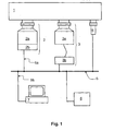
- Fig. 1: Schematische Darstellung einer ersten Anordnung mit Vakuumgerät.
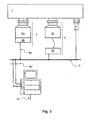
- Fig. 2: Schematische Darstellung einer zweiten Anordnung mit Vakuumgerät.
- Fig. 3: Schematische Darstellung einer dritten Anordnung mit Vakuumgerät.
- In den folgenden Figuren 1 bis 3 ist ein Rezipient 1 gezeigt, an dem über Flansche Vakuumgeräte angeschlossen sind. Der Rezipient kann eine einfache Vakuumkammer, eine Mehrkammeranlage oder Teil eines komplexen Vakuumsystems sein, wobei die Vakuumgeräte an verschiedenen Punkten des Systems angeordnet sein können. Als Vakuumgeräte sind in den Figuren 1 bis 3 eine erste Vakuumpumpe 2, eine zweite Vakuumpumpe 3 und ein Messgerät 4 dargestellt. Die Vakuumpumpe 2 weist einen Pumpenteil 2a mit dem Pumpsystem zur Erzeugung eines Vakuums und ein Betriebsgerät 2b auf. Dieses Betriebsgerät 2b beinhaltet die Steuerelektronik zum Antreiben der elektrischen und elektronischen Kompenenten des Pumpenteils 2a, insbesondere des Antriebsmotors. Im Betriebsgerät 2b können auch Leistungsteil und Netzteil angeordnet sein. Das Vakuumgerät 3 ist eine Vakuumpumpe, bei dem Pumpenteil 3a mit einem Pumpsystem und Betriebsgerät 3b getrennt voneinander sind und über eines oder mehrere Kabel miteinander in Verbindung stehen. Das Vakuumgerät 4 ist in den Beispielen als ein Messgerät ausgebildet, beispielsweise ein Druckmessgerät, wobei es mindestens eine Elektronik beinhaltet, von der Messwerte an anschließbare Geräte weitergegeben werden. Eine Steuereinheit 6 dient in bekannter Weise zur Steuerung der Vakuumgeräte. Hier kann beispielsweise von zentraler Stelle aus das Ein- und Ausschalten von einzelnen Vakuumgeräten abhängig von dem in dem Vakuumsystem ablaufenden Prozess geschehen. Zur Kommunikation zwischen den Vakuumgeräten und der Steuereinheit ist ein Bussystem 5 vorgesehen, an welches Steuereinheit und Vakuumgeräte angeschlossen sind, beispielsweise über eine Kabelverbindung 5a. Den angeschlossenen Geräten und Einheiten werden Adressen zugewiesen, an denen sie zur Kommunikation erreichbar sind. Als Komunikationsmittel zur Gestaltung des Bussystems können Kabel und Funkstrecken zum Einsatz kommen. Zur Kommunikation selbst können übliche Protokolle und Verfahren genutzt werden, beispielsweise Internetprotokolle oder solche, die im Bereich der industrieüblichen"speicherprogrammierbare Steuerung (SPS)" genutzt werden.
- Im ersten Ausführungsbeispiel nach Figur 1 ist eine Verwaltungseinheit 7 über eine Kabelverbindung 5b an das Bussystem 5 angeschlossen. Diese Verwaltungseinheit sammelt und verteilt Konfigurationsdaten der Vakuumgeräte. Das Bussystem ist in diesem Beispiel so ausgeführt, dass eine parallele Kommunikation durchgeführt werden kann. Insbesondere muss das Bussystem so gestaltet sein, dass es den quasigleichzeitigen Betrieb mit mehreren sogenannten Mastern erlaubt. Beispiele solcher Bussysteme sind Ethernet und der "Process Field Bus" (Profibus). Verwaltungs- und Steuereinheit sind in diesem Zusammenhang Master.
- Im zweiten Ausführungsbeispiel nach Figur 2 besitzt die Verwaltungseinheit 7 ein Funkmodul und kommuniziert über eine Funkverbindung 5b' mit einem an ein zweites Bussystem 5' angeschlossenen Funkmodul. Das zweite Bussystem ist parallel zum ersten Bussystem 5 angeordnet, so dass über beide ein Datenaustausch stattfinden kann. Mit der Funkverbindung 5b' als Verbindung zum Bussystem lässt sich besonders einfach eine temporär anschließbare Verwaltungseinheit realisieren. Sie kann dann beispielsweise die Form eines Personal Digital Assistant (PDA) annehmen oder ein mit einem Funkmodul ausgerüsteter tragbarer Computer ("Laptop") sein. Denkbar ist auch, das komplette Bussystem 5' oder Teile davon über Funkverbindungen aufzubauen.
- Im dritten Ausführungsbeispiel der Anordnung nach Figur 3 sind Steuereinheit und Verwaltungseinheit Teile einer Kontrolleinheit 9, welche über eine Verbindung 5b" an das Busssystem 5 angeschlossen ist. Diese Verbindung kann wie gezeigt aus mehreren Kabeln bestehen. Alternativ ist es denkbar, ein Kabel zu verwenden, auf welches durch geeignete Mittel die Daten beider Einheiten 6 und 7 gegeben werden. Über eine Außenverbindung 10 ist es der möglich Verwaltungseinheit, Daten zu empfangen und zu senden. Eine solche Verbindung kann beispielsweise eine Computernetzwerkverbindung wie Intranet oder Internet sein.
- Die Datenaustausche zwischen Vakuumgerät und Steuereinheit einerseits und Vakuumgerät und erfindungsgemäßer Verwaltungseinheit andererseits sind unabhängig voneinander. Das bedeutet insbesondere, dass die Verwaltungseinheit Daten aus dem Vakuumgerät auslesen kann, ohne den Datenaustausch zwischen Vakuumgerät und Steuereinheit wesentlich zu beeinträchtigen. Gewährleistet wird dies durch den oben beschriebenen Aufbau der Anordnung. Die im Datenaustausch übertragenen Daten setzen sich aus Steuerdaten, Betriebsdaten und Konfigurationsdaten zusammen. Dabei umfassen die Steuerdaten insbesondere Stellbefehle und Anweisungen, die vom Steuergerät auf das Vakuumgerät übertragen werden und beispielsweise Aktionen auslösen wie Auslesen eines Messwertes, Ändern der Drehzahl, und dergleichen. Die Betriebsdaten umfassen die Ist-Werte des Vakuumgeräts und werden von Steuer- und/oder Verwaltungseinheit nur ausgelesen. Hierbei handelt es sich beispielsweise um die Drehzahl, einen Druck oder eine Temperatur. Die Konfigurationsdaten umfassen die solche Daten wie Pumpentyp, Softwarestand, Einstellungen von Parametern wie beispielsweise Zyklenzahl und -dauer von Messwertaufnahmen, Temperatur von Temperaturmanagementsystemen, Kühlmittelfluss, und dergleichen. Die Summe aller Konfigurationsdaten eines Vakuumgeräts bildet einen Konfigurationsdatensatz, die Konfigurationsdaten beschreiben die Konfiguration des Vakuumgeräts.
- Das Verfahren zum Betreiben der oben beschriebenen Anordnung wird nachfolgend beispielhaft erläutert.
- Die Steuereinheit sendet über das Bussystem Daten an einzelne oder mehrere Vakuumgeräte. Diese Daten werden von den Betriebsgeräten an den Vakuumgeräten empfangen, als Befehle interpretiert und die zugehörigen Aktionen ausgelöst. Wenn das Vakuumgerät eine Vakuumpumpe ist, kann solche eine Aktion beispielsweise das Beschleunigen aus einem Standbyzustand mit verminderter Rotordrehzahl auf Enddrehzahl sein. Da das Ablaufen des Prozesses im Rezipienten bestimmte Aktionen und Zustände der Vakuumgeräte bedingt, senden die Betriebsgeräte der Vakuumgeräte Betriebsdaten an die Steuereinheit, die ihren Zustand beschreiben. Dieses Senden kann in regelmäßigen, vordefinierten Abständen oder als Reaktion auf einen entsprechenden Befehl der Steuereinheit geschehen. Das Versenden der Daten zwischen den Betriebsgeräten und der Steuereinheit stellt einen Datenaustausch dar.
- Die erfindungsgemäße Verwaltungseinheit sendet und empfängt Daten, wobei dieser Datenaustausch mit den Vakuumgeräten stattfindet und den zuvor beschriebenen Datenaustausch nicht behindert. Bei diesen Daten handelt es sich um Konfigurationsdaten oder Betriebsdaten oder beides zusammen. Diese Daten können vielfältig genutzt werden, beispielsweise können sie auf einem Anzeigegerät angezeigt, in einem Datenspeicher abgelegt oder über ein Computernetzwerk übertragen werden. Ein Beispiel für die Anwendung des Verfahrens ist, dass eine Vakuumpumpe einen Temperatursensor enthält, dessen Temperatursignal als Teil der Betriebsdaten an die Verwaltungseinheit gesendet wird. Diese speichert jeden Temperaturwert oder nur einen vorher festgelegten Anteil der Temperaturwerte ab und zeigt sich gleichzeitig auf einem Anzeigegerät, beispielsweise einem Bildschirm, an. Auch ist es möglich, dass die Verwaltungseinheit die aktuellen Betriebs- und Konfigurationsdaten der Anordnung ganz oder teilweise darstellt und so ihren Zustand repräsentiert und visualisiert.
- In einem weiteren Beispiel sendet die Verwaltungseinheit einen Befehl an das Vakuumgerät, auf welchen dieses als Reaktion seine Konfigurationsdaten übermittelt. Diese werden in einem Schritt B des Verfahrens in der Verwaltungseinheit unter Angabe der Adresse des Vakuumgeräts innerhalb des Bussystems, wodurch eine Zuordnung der Konfigurationsdaten zum Vakuumgerät stattfindet, abgespeichert. Anschließend wird das Vakuumgerät ausgetauscht und ein vom Bautyp her gleiches Vakuumgerät an seine Stelle in die Anordnung eingebaut. Wieder sendet die Verwaltungseinheit einen Befehl an die Adresse des Vakuumgeräts und erhält als Reaktion Konfigurationsdaten übermittelt. In der Verwaltungseinheit findet nun ein Vergleich des ganzen oder eines Teils des Konfigurationsdatensatzes statt. Ist das Ergebnis des Vergleiches so, dass die Konfigurationsdaten des neuen Vakuumgeräts nicht denen des alten Vakuumgeräts entsprechen, werden die im Speicher der Verwaltungseinheit abgelegten Konfigurationsdaten ganz oder teilweise auf das Vakuumgerät überspielt, so dass es in der Folge die Funktion des alten Vakuumgeräts erfüllen kann.
- Der Schritt A des Übertragens von Konfigurationsdaten oder Betriebsdaten oder beiden zusammen von einem Vakuumgerät an die Verwaltungseinheit kann ereignisgesteuert oder zyklisch erfolgen. Zyklisch heißt, dass nach Ablauf eines vorgegeben Zeitintervalls der Schritt wiederholt wird. Dieses Zeitintervall ist in der Verwaltungseinheit oder im Vakuumgerät abgelegt. Es kann festgelegt sein oder veränderlich sein. Ein Beispiel für eine Ereignissteuerung ist, wenn ein Anwender die Verwaltungseinheit bedient und dabei den Datenaustausch auslöst.
Claims (9)
- Anordnung mit Vakuumgerät (2, 3, 4), einem ersten Bussystem (5) und einer Steuereinheit (6), dadurch gekennzeichnet, dass eine Verwaltungseinheit (7) an dem Bussystem angeschlossen ist und das Bussystem Kommunikationsmittel aufweist, die für einen ersten Datenaustausch zwischen Vakuumgerät (2, 3, 4) und Steuereinheit (6) einerseits und einem zweiten Datenaustausch zwischen Vakuumgerät (2, 3, 4) und der Verwaltungseinheit (7) angepasst sind, wobei erster und zweiter Datenaustausch unabhängig voneinander sind.
- Anordnung nach Anspruch 1, dadurch gekennzeichnet, dass die Kommunikationsmittel ein zweites Bussystem (5') umfassen.
- Anordnung nach Anspruch 1 oder 2, dadurch gekennzeichnet, dass Steuereinheit und Verwaltungseinheit Teil einer Kontrolleinheit (9) sind.
- Verfahren zum Betreiben einer Anordnung mit allen Merkmalen gemäß einem oder mehreren der vorhergehenden Ansprüche, wobei das Verfahren einen Schritt A aufweist, in welchem im zweiten Datenaustausch entweder die Konfigurationsdaten oder die Betriebsdaten oder beide zusammen vom Vakuumgerät (2, 3, 4) an die Verwaltungseinheit (7) übertragen werden.
- Verfahren nach Anspruch 4, dadurch gekennzeichnet, dass in einem Schritt B die Konfigurationsdaten in einem Konfigurationsdatenspeicher abgelegt werden, wobei eine Zuordnung zu dem Vakuumgerät (2, 3, 4) stattfindet, von dem die Konfigurationsdaten stammen.
- Verfahren nach Anspruch 5, dadurch gekennzeichnet, dass die Verwaltungseinheit (7) die im zweiten Datenaustausch übermittelten Konfigurationsdaten ganz oder teilweise mit gleichartigen, in der Verwaltungseinheit (7) vorliegenden Konfigurationsdaten vergleicht.
- Verfahren nach Anspruch 5 oder 6, dadurch gekennzeichnet, dass in einem weiteren Schritt die Verwaltungseinheit (7) im zweiten Datenaustausch entweder Konfigurationsdaten oder eine Betriebssoftware oder beide zusammen an das Vakuumgerät (2, 3, 4) übermittelt.
- Verfahren nach Anspruch 4, dadurch gekennzeichnet, dass der Schritt A zyklisch wiederholt wird.
- Verfahren nach Anspruch 4, dadurch gekennzeichnet, dass der Schritt A ereignisgesteuert ist.
Applications Claiming Priority (1)
| Application Number | Priority Date | Filing Date | Title |
|---|---|---|---|
| DE102006045022.1A DE102006045022B4 (de) | 2006-09-23 | 2006-09-23 | Anordnung mit Vakuumgerät und Verfahren zu derem Betrieb |
Publications (3)
| Publication Number | Publication Date |
|---|---|
| EP1903530A2 true EP1903530A2 (de) | 2008-03-26 |
| EP1903530A3 EP1903530A3 (de) | 2014-09-17 |
| EP1903530B1 EP1903530B1 (de) | 2020-07-22 |
Family
ID=38969547
Family Applications (1)
| Application Number | Title | Priority Date | Filing Date |
|---|---|---|---|
| EP07017431.3A Active EP1903530B1 (de) | 2006-09-23 | 2007-09-06 | Anordnung mit Vakuumgerät und Verfahren zu deren Betrieb |
Country Status (2)
| Country | Link |
|---|---|
| EP (1) | EP1903530B1 (de) |
| DE (1) | DE102006045022B4 (de) |
Cited By (5)
| Publication number | Priority date | Publication date | Assignee | Title |
|---|---|---|---|---|
| EP2827314A1 (de) * | 2013-06-20 | 2015-01-21 | Pfeiffer Vacuum GmbH | Vakuumanordnung mit einem Vakuumgerät sowie Verfahren zur Erfassung von in einer Kommunikationsleitung zwischen einem Vakuumgerät und einer zentralen Steuereinrichtung kommunizierten Daten |
| EP3620661A1 (de) * | 2019-08-30 | 2020-03-11 | Pfeiffer Vacuum Gmbh | Anschlussvorrichtung, system und verfahren zum betreiben einer anschlussvorrichtung |
| EP3620663A1 (de) * | 2018-09-06 | 2020-03-11 | Pfeiffer Vacuum Gmbh | Vakuumvorrichtung |
| EP3626973A1 (de) * | 2019-08-12 | 2020-03-25 | Pfeiffer Vacuum Gmbh | Vakuumsystem und verfahren zum identifizieren elektronischer module in einem solchen |
| EP3951738A3 (de) * | 2021-12-13 | 2022-07-06 | Pfeiffer Vacuum Technology AG | Vorrichtung und verfahren zur kommunikation mit einem vakuumgerät |
Families Citing this family (1)
| Publication number | Priority date | Publication date | Assignee | Title |
|---|---|---|---|---|
| DE102024132173B3 (de) * | 2024-11-05 | 2026-02-12 | Endress+Hauser Flowtec Ag | Messdatenverarbeitungssystem und Prozessanlage |
Family Cites Families (7)
| Publication number | Priority date | Publication date | Assignee | Title |
|---|---|---|---|---|
| ATE187824T1 (de) * | 1994-10-24 | 2000-01-15 | Fisher Rosemount Systems Inc | Vorrichtung, die einen zugang zu feldgeräten in einem verteilten steuerungssystem gestattet |
| US5793963A (en) * | 1994-10-24 | 1998-08-11 | Fisher Rosemount Systems, Inc. | Apparatus for providing non-redundant secondary access to field devices in a distributed control system |
| US5971711A (en) * | 1996-05-21 | 1999-10-26 | Ebara Corporation | Vacuum pump control system |
| US6272400B1 (en) * | 1998-07-13 | 2001-08-07 | Helix Technology Corporation | Vacuum network controller |
| DE10114127A1 (de) * | 2001-03-22 | 2002-09-26 | Abb Patent Gmbh | Verfahren zur Kommunikation mit einem Feldgerät |
| US7016751B2 (en) * | 2001-07-13 | 2006-03-21 | Helix Technology Corporation | Vacuum system central control information server |
| DE102004036046A1 (de) | 2004-07-24 | 2006-02-16 | Robert Bosch Gmbh | System und Verfahren zur Steuerung oder Regelung der Betriebsabläufe bei einem Fahrzeug |
-
2006
- 2006-09-23 DE DE102006045022.1A patent/DE102006045022B4/de active Active
-
2007
- 2007-09-06 EP EP07017431.3A patent/EP1903530B1/de active Active
Cited By (5)
| Publication number | Priority date | Publication date | Assignee | Title |
|---|---|---|---|---|
| EP2827314A1 (de) * | 2013-06-20 | 2015-01-21 | Pfeiffer Vacuum GmbH | Vakuumanordnung mit einem Vakuumgerät sowie Verfahren zur Erfassung von in einer Kommunikationsleitung zwischen einem Vakuumgerät und einer zentralen Steuereinrichtung kommunizierten Daten |
| EP3620663A1 (de) * | 2018-09-06 | 2020-03-11 | Pfeiffer Vacuum Gmbh | Vakuumvorrichtung |
| EP3626973A1 (de) * | 2019-08-12 | 2020-03-25 | Pfeiffer Vacuum Gmbh | Vakuumsystem und verfahren zum identifizieren elektronischer module in einem solchen |
| EP3620661A1 (de) * | 2019-08-30 | 2020-03-11 | Pfeiffer Vacuum Gmbh | Anschlussvorrichtung, system und verfahren zum betreiben einer anschlussvorrichtung |
| EP3951738A3 (de) * | 2021-12-13 | 2022-07-06 | Pfeiffer Vacuum Technology AG | Vorrichtung und verfahren zur kommunikation mit einem vakuumgerät |
Also Published As
| Publication number | Publication date |
|---|---|
| DE102006045022B4 (de) | 2026-04-23 |
| DE102006045022A1 (de) | 2008-03-27 |
| EP1903530B1 (de) | 2020-07-22 |
| EP1903530A3 (de) | 2014-09-17 |
Similar Documents
| Publication | Publication Date | Title |
|---|---|---|
| EP4004664B1 (de) | Verfahren zur verifizierung des in einem asset management system eingetragenen feldgerätebestands | |
| EP0923038B1 (de) | Messeinrichtung zur Ermittlung von physikalischen und/oder chemischen Eigenschaften von Gasen, Flüssigkeiten und/oder Feststoffen | |
| DE102010029952B4 (de) | Verfahren zum Integrieren von zumindest einem Feldgerät in ein Netzwerk der Automatisierungstechnik | |
| EP1088259B1 (de) | Elektronische steuerung für anlagen der druckluft- oder vakuumerzeugung | |
| EP1525518B9 (de) | Verfahren zum aktualisieren von gerätebeschreibungen für feldgeräte der prozessautomatisierungstechnik | |
| EP2659317B1 (de) | Feldgerät mit langzeit-firmware-kompatibilität | |
| EP1779203B1 (de) | Parameteridentifikation für feldgeräte in der automatisierungstechnik | |
| DE102007026678A1 (de) | Verfahren zum Austausch eines defekten Feldgerätes gegen ein neues Feldgerät in einem über digitalen Feldbus kommunizierenden System, insbesondere Automatisierungssystem | |
| DE10159697A1 (de) | Redundante Einrichtungen in einem Prozesssteuersystem | |
| EP1903530B1 (de) | Anordnung mit Vakuumgerät und Verfahren zu deren Betrieb | |
| DE102012105446B4 (de) | Vorrichtung zur Bestimmung und/oder Überwachung einer chemischen oder physikalischen Prozessgröße in der Automatisierungstechnik | |
| WO2009074544A1 (de) | Verfahren zum betreiben eines systems aufweisend ein feldgerät und ein bediensystem | |
| EP3384352B1 (de) | Verfahren und system zur optimierung der inbetriebnahme von zumindest einem einer vielzahl von feldgeräten der automatisierungstechnik | |
| DE102007029321B4 (de) | Verfahren zum Betreiben eines Feldgerätes in einem benutzerfreundlichen Modus | |
| EP3637205A1 (de) | Bildaufschaltung auf einem operator station client | |
| EP4036543A1 (de) | Drucksensor | |
| EP3384353B1 (de) | Verfahren und system zur optimierung der bedienung von zumindest einem einer vielzahl von feldgeräten der automatisierungstechnik | |
| WO2006018345A1 (de) | Verfahren zum betreiben eines feldgeräts der automatisierungstechnik | |
| EP1854055A1 (de) | Engineeringsystem | |
| WO2007048741A1 (de) | Vorrichtung zum betreiben einer prozessanlage | |
| WO2019011603A1 (de) | Verfahren und datenumsetzungseinheit zum überwachen einer anlage der automatisierungstechnik | |
| DE10157539A1 (de) | Engineeringsystem und Automatisierungssystem | |
| EP1431898A2 (de) | Automatisierungssystem und Verfahren zum Betrieb eines Automatisierungssystems | |
| EP3970345B1 (de) | Konfigurationsfreie ausgabe von in ethernet-telegrammen enthaltenen nutzdaten | |
| DE102006004633A1 (de) | Verteiltes Automatisierungssystem |
Legal Events
| Date | Code | Title | Description |
|---|---|---|---|
| PUAI | Public reference made under article 153(3) epc to a published international application that has entered the european phase |
Free format text: ORIGINAL CODE: 0009012 |
|
| AK | Designated contracting states |
Kind code of ref document: A2 Designated state(s): AT BE BG CH CY CZ DE DK EE ES FI FR GB GR HU IE IS IT LI LT LU LV MC MT NL PL PT RO SE SI SK TR |
|
| AX | Request for extension of the european patent |
Extension state: AL BA HR MK YU |
|
| PUAL | Search report despatched |
Free format text: ORIGINAL CODE: 0009013 |
|
| AK | Designated contracting states |
Kind code of ref document: A3 Designated state(s): AT BE BG CH CY CZ DE DK EE ES FI FR GB GR HU IE IS IT LI LT LU LV MC MT NL PL PT RO SE SI SK TR |
|
| AX | Request for extension of the european patent |
Extension state: AL BA HR MK RS |
|
| RIC1 | Information provided on ipc code assigned before grant |
Ipc: G08C 19/00 20060101AFI20140812BHEP Ipc: G08C 17/02 20060101ALI20140812BHEP |
|
| 17P | Request for examination filed |
Effective date: 20150317 |
|
| RBV | Designated contracting states (corrected) |
Designated state(s): AT BE BG CH CY CZ DE DK EE ES FI FR GB GR HU IE IS IT LI LT LU LV MC MT NL PL PT RO SE SI SK TR |
|
| AKX | Designation fees paid |
Designated state(s): AT BE BG CH CY CZ DE DK EE ES FI FR GB GR HU IE IS IT LI LT LU LV MC MT NL PL PT RO SE SI SK TR |
|
| AXX | Extension fees paid |
Extension state: MK Extension state: BA Extension state: HR Extension state: AL Extension state: RS |
|
| STAA | Information on the status of an ep patent application or granted ep patent |
Free format text: STATUS: EXAMINATION IS IN PROGRESS |
|
| 17Q | First examination report despatched |
Effective date: 20180411 |
|
| GRAP | Despatch of communication of intention to grant a patent |
Free format text: ORIGINAL CODE: EPIDOSNIGR1 |
|
| STAA | Information on the status of an ep patent application or granted ep patent |
Free format text: STATUS: GRANT OF PATENT IS INTENDED |
|
| INTG | Intention to grant announced |
Effective date: 20200330 |
|
| GRAS | Grant fee paid |
Free format text: ORIGINAL CODE: EPIDOSNIGR3 |
|
| GRAA | (expected) grant |
Free format text: ORIGINAL CODE: 0009210 |
|
| STAA | Information on the status of an ep patent application or granted ep patent |
Free format text: STATUS: THE PATENT HAS BEEN GRANTED |
|
| AK | Designated contracting states |
Kind code of ref document: B1 Designated state(s): AT BE BG CH CY CZ DE DK EE ES FI FR GB GR HU IE IS IT LI LT LU LV MC MT NL PL PT RO SE SI SK TR |
|
| REG | Reference to a national code |
Ref country code: GB Ref legal event code: FG4D Free format text: NOT ENGLISH |
|
| REG | Reference to a national code |
Ref country code: CH Ref legal event code: EP |
|
| REG | Reference to a national code |
Ref country code: DE Ref legal event code: R096 Ref document number: 502007016901 Country of ref document: DE |
|
| REG | Reference to a national code |
Ref country code: AT Ref legal event code: REF Ref document number: 1294148 Country of ref document: AT Kind code of ref document: T Effective date: 20200815 |
|
| REG | Reference to a national code |
Ref country code: IE Ref legal event code: FG4D Free format text: LANGUAGE OF EP DOCUMENT: GERMAN |
|
| REG | Reference to a national code |
Ref country code: LT Ref legal event code: MG4D |
|
| PG25 | Lapsed in a contracting state [announced via postgrant information from national office to epo] |
Ref country code: LT Free format text: LAPSE BECAUSE OF FAILURE TO SUBMIT A TRANSLATION OF THE DESCRIPTION OR TO PAY THE FEE WITHIN THE PRESCRIBED TIME-LIMIT Effective date: 20200722 Ref country code: PT Free format text: LAPSE BECAUSE OF FAILURE TO SUBMIT A TRANSLATION OF THE DESCRIPTION OR TO PAY THE FEE WITHIN THE PRESCRIBED TIME-LIMIT Effective date: 20201123 Ref country code: SE Free format text: LAPSE BECAUSE OF FAILURE TO SUBMIT A TRANSLATION OF THE DESCRIPTION OR TO PAY THE FEE WITHIN THE PRESCRIBED TIME-LIMIT Effective date: 20200722 Ref country code: BG Free format text: LAPSE BECAUSE OF FAILURE TO SUBMIT A TRANSLATION OF THE DESCRIPTION OR TO PAY THE FEE WITHIN THE PRESCRIBED TIME-LIMIT Effective date: 20201022 Ref country code: ES Free format text: LAPSE BECAUSE OF FAILURE TO SUBMIT A TRANSLATION OF THE DESCRIPTION OR TO PAY THE FEE WITHIN THE PRESCRIBED TIME-LIMIT Effective date: 20200722 Ref country code: GR Free format text: LAPSE BECAUSE OF FAILURE TO SUBMIT A TRANSLATION OF THE DESCRIPTION OR TO PAY THE FEE WITHIN THE PRESCRIBED TIME-LIMIT Effective date: 20201023 Ref country code: FI Free format text: LAPSE BECAUSE OF FAILURE TO SUBMIT A TRANSLATION OF THE DESCRIPTION OR TO PAY THE FEE WITHIN THE PRESCRIBED TIME-LIMIT Effective date: 20200722 |
|
| PG25 | Lapsed in a contracting state [announced via postgrant information from national office to epo] |
Ref country code: LV Free format text: LAPSE BECAUSE OF FAILURE TO SUBMIT A TRANSLATION OF THE DESCRIPTION OR TO PAY THE FEE WITHIN THE PRESCRIBED TIME-LIMIT Effective date: 20200722 Ref country code: PL Free format text: LAPSE BECAUSE OF FAILURE TO SUBMIT A TRANSLATION OF THE DESCRIPTION OR TO PAY THE FEE WITHIN THE PRESCRIBED TIME-LIMIT Effective date: 20200722 Ref country code: IS Free format text: LAPSE BECAUSE OF FAILURE TO SUBMIT A TRANSLATION OF THE DESCRIPTION OR TO PAY THE FEE WITHIN THE PRESCRIBED TIME-LIMIT Effective date: 20201122 |
|
| PG25 | Lapsed in a contracting state [announced via postgrant information from national office to epo] |
Ref country code: NL Free format text: LAPSE BECAUSE OF FAILURE TO SUBMIT A TRANSLATION OF THE DESCRIPTION OR TO PAY THE FEE WITHIN THE PRESCRIBED TIME-LIMIT Effective date: 20200722 |
|
| REG | Reference to a national code |
Ref country code: DE Ref legal event code: R097 Ref document number: 502007016901 Country of ref document: DE |
|
| PG25 | Lapsed in a contracting state [announced via postgrant information from national office to epo] |
Ref country code: RO Free format text: LAPSE BECAUSE OF FAILURE TO SUBMIT A TRANSLATION OF THE DESCRIPTION OR TO PAY THE FEE WITHIN THE PRESCRIBED TIME-LIMIT Effective date: 20200722 Ref country code: MC Free format text: LAPSE BECAUSE OF FAILURE TO SUBMIT A TRANSLATION OF THE DESCRIPTION OR TO PAY THE FEE WITHIN THE PRESCRIBED TIME-LIMIT Effective date: 20200722 Ref country code: EE Free format text: LAPSE BECAUSE OF FAILURE TO SUBMIT A TRANSLATION OF THE DESCRIPTION OR TO PAY THE FEE WITHIN THE PRESCRIBED TIME-LIMIT Effective date: 20200722 Ref country code: DK Free format text: LAPSE BECAUSE OF FAILURE TO SUBMIT A TRANSLATION OF THE DESCRIPTION OR TO PAY THE FEE WITHIN THE PRESCRIBED TIME-LIMIT Effective date: 20200722 |
|
| REG | Reference to a national code |
Ref country code: CH Ref legal event code: PL |
|
| PLBE | No opposition filed within time limit |
Free format text: ORIGINAL CODE: 0009261 |
|
| STAA | Information on the status of an ep patent application or granted ep patent |
Free format text: STATUS: NO OPPOSITION FILED WITHIN TIME LIMIT |
|
| REG | Reference to a national code |
Ref country code: BE Ref legal event code: MM Effective date: 20200930 |
|
| 26N | No opposition filed |
Effective date: 20210423 |
|
| PG25 | Lapsed in a contracting state [announced via postgrant information from national office to epo] |
Ref country code: SK Free format text: LAPSE BECAUSE OF FAILURE TO SUBMIT A TRANSLATION OF THE DESCRIPTION OR TO PAY THE FEE WITHIN THE PRESCRIBED TIME-LIMIT Effective date: 20200722 Ref country code: LU Free format text: LAPSE BECAUSE OF NON-PAYMENT OF DUE FEES Effective date: 20200906 |
|
| PG25 | Lapsed in a contracting state [announced via postgrant information from national office to epo] |
Ref country code: FR Free format text: LAPSE BECAUSE OF NON-PAYMENT OF DUE FEES Effective date: 20200922 |
|
| PG25 | Lapsed in a contracting state [announced via postgrant information from national office to epo] |
Ref country code: SI Free format text: LAPSE BECAUSE OF FAILURE TO SUBMIT A TRANSLATION OF THE DESCRIPTION OR TO PAY THE FEE WITHIN THE PRESCRIBED TIME-LIMIT Effective date: 20200722 Ref country code: LI Free format text: LAPSE BECAUSE OF NON-PAYMENT OF DUE FEES Effective date: 20200930 Ref country code: IE Free format text: LAPSE BECAUSE OF NON-PAYMENT OF DUE FEES Effective date: 20200906 Ref country code: CH Free format text: LAPSE BECAUSE OF NON-PAYMENT OF DUE FEES Effective date: 20200930 Ref country code: BE Free format text: LAPSE BECAUSE OF NON-PAYMENT OF DUE FEES Effective date: 20200930 |
|
| REG | Reference to a national code |
Ref country code: NL Ref legal event code: MP Effective date: 20200722 |
|
| REG | Reference to a national code |
Ref country code: AT Ref legal event code: MM01 Ref document number: 1294148 Country of ref document: AT Kind code of ref document: T Effective date: 20200906 |
|
| PG25 | Lapsed in a contracting state [announced via postgrant information from national office to epo] |
Ref country code: AT Free format text: LAPSE BECAUSE OF NON-PAYMENT OF DUE FEES Effective date: 20200906 |
|
| PG25 | Lapsed in a contracting state [announced via postgrant information from national office to epo] |
Ref country code: TR Free format text: LAPSE BECAUSE OF FAILURE TO SUBMIT A TRANSLATION OF THE DESCRIPTION OR TO PAY THE FEE WITHIN THE PRESCRIBED TIME-LIMIT Effective date: 20200722 Ref country code: MT Free format text: LAPSE BECAUSE OF FAILURE TO SUBMIT A TRANSLATION OF THE DESCRIPTION OR TO PAY THE FEE WITHIN THE PRESCRIBED TIME-LIMIT Effective date: 20200722 Ref country code: CY Free format text: LAPSE BECAUSE OF FAILURE TO SUBMIT A TRANSLATION OF THE DESCRIPTION OR TO PAY THE FEE WITHIN THE PRESCRIBED TIME-LIMIT Effective date: 20200722 |
|
| PGFP | Annual fee paid to national office [announced via postgrant information from national office to epo] |
Ref country code: IT Payment date: 20250923 Year of fee payment: 19 |
|
| PGFP | Annual fee paid to national office [announced via postgrant information from national office to epo] |
Ref country code: GB Payment date: 20250918 Year of fee payment: 19 |
|
| PGFP | Annual fee paid to national office [announced via postgrant information from national office to epo] |
Ref country code: CZ Payment date: 20250828 Year of fee payment: 19 |
|
| PGFP | Annual fee paid to national office [announced via postgrant information from national office to epo] |
Ref country code: DE Payment date: 20251126 Year of fee payment: 19 |