EP2827301B1 - Image generation device, method, and program - Google Patents
Image generation device, method, and program Download PDFInfo
- Publication number
- EP2827301B1 EP2827301B1 EP13762032.4A EP13762032A EP2827301B1 EP 2827301 B1 EP2827301 B1 EP 2827301B1 EP 13762032 A EP13762032 A EP 13762032A EP 2827301 B1 EP2827301 B1 EP 2827301B1
- Authority
- EP
- European Patent Office
- Prior art keywords
- pixel
- value
- opacity curve
- region
- pixels
- Prior art date
- Legal status (The legal status is an assumption and is not a legal conclusion. Google has not performed a legal analysis and makes no representation as to the accuracy of the status listed.)
- Active
Links
- 238000000034 method Methods 0.000 title claims description 21
- 210000004204 blood vessel Anatomy 0.000 claims description 67
- 238000009877 rendering Methods 0.000 claims description 41
- 238000005070 sampling Methods 0.000 claims description 13
- 238000003860 storage Methods 0.000 description 10
- 230000006870 function Effects 0.000 description 6
- 238000003384 imaging method Methods 0.000 description 6
- 238000009826 distribution Methods 0.000 description 5
- 238000005516 engineering process Methods 0.000 description 4
- 239000002872 contrast media Substances 0.000 description 3
- 238000010586 diagram Methods 0.000 description 3
- 239000000284 extract Substances 0.000 description 3
- 210000001519 tissue Anatomy 0.000 description 3
- 230000000694 effects Effects 0.000 description 2
- 210000002216 heart Anatomy 0.000 description 2
- 210000004185 liver Anatomy 0.000 description 2
- 239000011159 matrix material Substances 0.000 description 2
- 210000000056 organ Anatomy 0.000 description 2
- 238000002604 ultrasonography Methods 0.000 description 2
- 238000012800 visualization Methods 0.000 description 2
- 210000000988 bone and bone Anatomy 0.000 description 1
- 210000000621 bronchi Anatomy 0.000 description 1
- 238000005266 casting Methods 0.000 description 1
- 238000013170 computed tomography imaging Methods 0.000 description 1
- 238000000605 extraction Methods 0.000 description 1
- 210000000936 intestine Anatomy 0.000 description 1
- 239000007788 liquid Substances 0.000 description 1
- 238000005457 optimization Methods 0.000 description 1
- 230000004044 response Effects 0.000 description 1
- 230000011218 segmentation Effects 0.000 description 1
- 238000002603 single-photon emission computed tomography Methods 0.000 description 1
Images


Classifications
-
- G—PHYSICS
- G06—COMPUTING; CALCULATING OR COUNTING
- G06T—IMAGE DATA PROCESSING OR GENERATION, IN GENERAL
- G06T15/00—3D [Three Dimensional] image rendering
- G06T15/08—Volume rendering
-
- A—HUMAN NECESSITIES
- A61—MEDICAL OR VETERINARY SCIENCE; HYGIENE
- A61B—DIAGNOSIS; SURGERY; IDENTIFICATION
- A61B6/00—Apparatus or devices for radiation diagnosis; Apparatus or devices for radiation diagnosis combined with radiation therapy equipment
- A61B6/46—Arrangements for interfacing with the operator or the patient
- A61B6/461—Displaying means of special interest
- A61B6/466—Displaying means of special interest adapted to display 3D data
-
- A—HUMAN NECESSITIES
- A61—MEDICAL OR VETERINARY SCIENCE; HYGIENE
- A61B—DIAGNOSIS; SURGERY; IDENTIFICATION
- A61B6/00—Apparatus or devices for radiation diagnosis; Apparatus or devices for radiation diagnosis combined with radiation therapy equipment
- A61B6/50—Apparatus or devices for radiation diagnosis; Apparatus or devices for radiation diagnosis combined with radiation therapy equipment specially adapted for specific body parts; specially adapted for specific clinical applications
- A61B6/504—Apparatus or devices for radiation diagnosis; Apparatus or devices for radiation diagnosis combined with radiation therapy equipment specially adapted for specific body parts; specially adapted for specific clinical applications for diagnosis of blood vessels, e.g. by angiography
-
- A—HUMAN NECESSITIES
- A61—MEDICAL OR VETERINARY SCIENCE; HYGIENE
- A61B—DIAGNOSIS; SURGERY; IDENTIFICATION
- A61B8/00—Diagnosis using ultrasonic, sonic or infrasonic waves
- A61B8/08—Detecting organic movements or changes, e.g. tumours, cysts, swellings
- A61B8/0891—Detecting organic movements or changes, e.g. tumours, cysts, swellings for diagnosis of blood vessels
-
- A—HUMAN NECESSITIES
- A61—MEDICAL OR VETERINARY SCIENCE; HYGIENE
- A61B—DIAGNOSIS; SURGERY; IDENTIFICATION
- A61B8/00—Diagnosis using ultrasonic, sonic or infrasonic waves
- A61B8/46—Ultrasonic, sonic or infrasonic diagnostic devices with special arrangements for interfacing with the operator or the patient
- A61B8/461—Displaying means of special interest
- A61B8/466—Displaying means of special interest adapted to display 3D data
-
- A—HUMAN NECESSITIES
- A61—MEDICAL OR VETERINARY SCIENCE; HYGIENE
- A61B—DIAGNOSIS; SURGERY; IDENTIFICATION
- A61B2576/00—Medical imaging apparatus involving image processing or analysis
-
- A—HUMAN NECESSITIES
- A61—MEDICAL OR VETERINARY SCIENCE; HYGIENE
- A61B—DIAGNOSIS; SURGERY; IDENTIFICATION
- A61B5/00—Measuring for diagnostic purposes; Identification of persons
- A61B5/48—Other medical applications
- A61B5/4887—Locating particular structures in or on the body
- A61B5/489—Blood vessels
-
- A—HUMAN NECESSITIES
- A61—MEDICAL OR VETERINARY SCIENCE; HYGIENE
- A61B—DIAGNOSIS; SURGERY; IDENTIFICATION
- A61B8/00—Diagnosis using ultrasonic, sonic or infrasonic waves
- A61B8/48—Diagnostic techniques
- A61B8/483—Diagnostic techniques involving the acquisition of a 3D volume of data
-
- G—PHYSICS
- G06—COMPUTING; CALCULATING OR COUNTING
- G06T—IMAGE DATA PROCESSING OR GENERATION, IN GENERAL
- G06T2200/00—Indexing scheme for image data processing or generation, in general
- G06T2200/04—Indexing scheme for image data processing or generation, in general involving 3D image data
-
- G—PHYSICS
- G06—COMPUTING; CALCULATING OR COUNTING
- G06T—IMAGE DATA PROCESSING OR GENERATION, IN GENERAL
- G06T2210/00—Indexing scheme for image generation or computer graphics
- G06T2210/41—Medical
-
- G—PHYSICS
- G16—INFORMATION AND COMMUNICATION TECHNOLOGY [ICT] SPECIALLY ADAPTED FOR SPECIFIC APPLICATION FIELDS
- G16H—HEALTHCARE INFORMATICS, i.e. INFORMATION AND COMMUNICATION TECHNOLOGY [ICT] SPECIALLY ADAPTED FOR THE HANDLING OR PROCESSING OF MEDICAL OR HEALTHCARE DATA
- G16H30/00—ICT specially adapted for the handling or processing of medical images
- G16H30/40—ICT specially adapted for the handling or processing of medical images for processing medical images, e.g. editing
Definitions
- the present invention relates to an image generation apparatus, method, and program that generates a pseudo three-dimensional image by performing volume rendering on a three-dimensional image.
- processing for generating and displaying a pseudo three-dimensional image has been performed in which three-dimensional image data of a subject obtained by CT equipment, MRI equipment, ultrasonic diagnostic equipment, or the like are stereoscopically visualized on a two-dimensional plane using computer graphics technologies in order to facilitate understanding of a three-dimensional structure of the subject and the like.
- a volume rendering method is known in which opacity and color information of R, G, B are set to each pixel value (voxel value) constituting a three-dimensional image and the visualization is achieved by performing ray-casting on each pixel on a projection plane from the observation side.
- Non-Patent Document 1 proposes that different tissues having the same signal value are represented by different color or opacity by applying a different color map and/or opacity curve to each object region.
- Patent Document 1 Japanese Unexamined Patent Publication No. 2011-212219
- Non-Patent Document 1 H. Imai "I see! ! The Bible of the Way of Thinking and Processing - Three-Dimensional Medical Image", Shujunsha, P105, 2003
- US 2008/278488 A1 discloses an apparatus and a method for volume rendering. Specifically, the document is related to regional optimization of an opacity function.
- the document discloses a method for segmenting image data to thereby locate boundaries within an image, determining regional opacity functions using the image data in the vicinity of the segmented boundaries, and volume rendering the image data utilizing the regional opacity functions to display an image.
- the document discloses an adjustment of an opacity curve of an ultrasound image. The opacity curve is adjusted for pixels included in a near-field region of the boundaries using the values of pixels in the vicinity of the boundary in the ultrasound image.
- a method that further visualizes and makes that portion extractable by performing imaging after injecting a special liquid called a contrast agent is sometimes used so that pixel values of the blood vessel differ from those of other organs in a three-dimensional image.
- a variation in pixel value occurs from place to place even in the same blood vessel region due to the imaging timing or the amount of the contrast agent. Therefore, when generating an image that represents a wide range of blood vessel region, even for one target object tissue of blood vessel, the simple application of one color map and/or an opacity curve causes a problem that a three-dimensional morphology of the entire blood vessel cannot be represented accurately.
- the problem due to the variation in pixel value may possibly occur by a partial volume effect.
- a blood vessel which should have actually a high pixel value is imaged with a pixel value lower than the real value influenced by the surrounding pixel values at the time of the imaging.
- Patent Document 1 proposes a method for dynamically correcting color map and/or opacity curve with respect to each image, but the method is based on the assumption that the depiction range of each image is so small that the variation in pixel value is negligible and related to how to decide one opacity curve used for generating on image. Therefore, the method does not solve the aforementioned problem when generating an image representing a wider object range.
- an object of the present invention to provide an image generation apparatus, method, and program capable of generating an image which depicts three-dimensional morphology of a predetermined target object more accurately when generating a pseudo three-dimensional image by performing volume rendering.
- the opacity curve setting section may be a section that obtains, with respect to each of the at least some pixels, a shift amount of opacity curve based on a subtraction value obtained by subtracting a representative value of pixel values in the whole region from the representative value of pixels in the adjacent region of the pixel concerned and sets an opacity curve obtained by shifting the base opacity curve by the obtained shift amount in a pixel value direction as the opacity curve to be set to the pixel concerned in the volume rendering.
- pixel value direction refers to, when the opacity curve is set in a coordinate system with one axis (e.g., horizontal axis) representing the pixel value and the other axis (e.g., vertical axis) representing the opacity, a direction of the axis representing the pixel value.
- one axis e.g., horizontal axis
- the other axis e.g., vertical axis
- shift amount When obtaining the shift amount based on the subtraction value, a value having the same positive or negative sign as that of the subtraction value is obtained as the shift amount.
- the absolute value of the shift amount may be the same as the absolute value of the subtraction value or a value obtained by multiplying the value with a predetermined coefficient other than 1.
- shifting by the shift amount refers to shifting to plus direction of the axis representing the pixel value if the sign of the shift amount is plus while shifting to minus direction of the axis representing the pixel value if the sign of the shift amount is minus.
- the opacity curve setting section may be a section that obtains, with respect to each of some pixels obtained by sampling the pixels in the whole region at a predetermined interval, a representative value of pixels in an adjacent region of a pixel concerned, obtains a shift amount of opacity curve based on a difference between the obtained representative value and a representative value of pixel values in the whole region, and sets an opacity curve obtained by shifting the base opacity curve by the obtained shift amount to a pixel value direction as the opacity curve to be applied to the pixel concerned, and obtains, with respect to each of pixels in the whole region other than the sampled some pixels, an estimated value of shift amount at a pixel concerned by interpolation using the shift amount of each of the two or more sampled pixels located adjacent to the pixel concerned and sets an opacity curve obtained by shifting the base opacity curve by the determined estimated value in a pixel value direction as the opacity curve to be applied to the pixel concerned in
- the representative value of the pixel values in the adjacent region may be a mode value, a median value, or an average value of the pixel values in the adjacent region, an average value of pixel values of all pixel values in the adjacent region which fall in a range of predetermined width of pixel values from the mode value or the median value of the pixels in the adjacent region, or a mode value or a median value of pixel values of all pixel values in the adjacent region which fall in a range of predetermined width of pixel values from the mode value or the median value of the pixels in the adjacent region.
- the representative value of the pixels in the whole region may be a value of the same type as that of the representative value of the pixels in the adjacent region or a value of different type from that of the representative value of the pixels in the adjacent region.
- the representative value of the pixels in the adjacent region is the average value
- the representative value of the pixels in the whole region may be the average value or the mode value of the pixels in the whole region.
- the predetermined target object may be a blood vessel.
- An image generation method of the present invention performs the processing performed by each section of the image generation apparatus with at least one computer.
- An image generation program of the present invention causes at least one computer to perform the processing performed by each section of the image generation apparatus.
- the programs are recorded on recording media, such as CD-ROM, DVD, and the like, or recorded on an auxiliary storage of a server computer or a network storage in a downloadable manner and supplied to the user.
- a whole region representing a predetermined target object is identified from the three-dimensional image, a base opacity curve is set to the identified whole region, with respect to each of at least some pixels in the identified whole region, a representative value of pixel values in an adjacent region of a pixel concerned is obtained, and an opacity curve obtained by modifying the base opacity curve using the obtained representative value is set as the opacity curve to be applied to the pixel concerned in the volume rendering.
- This effect is more significant if the predetermined target object is a blood vessel and further significant if the three-dimensional image is an image obtained by injecting a contrast agent into the blood vessel.
- the representative value of the pixel values in the adjacent region is the mode value or the median value of the pixel values in the adjacent region, an extreme value due to noise, if present in the adjacent region, is less likely to be reflected to the representative value.
- the representative value of the pixel values in the adjacent region is an average value, a mode value, or a median value of pixel values of all pixel values in the adjacent region which fall in a range of predetermined width of pixel values from the mode value or the median value of the pixels in the adjacent region, an extreme value that presents on the maximum or the minimum side of the pixel values in the adjacent region is less likely to be reflected to the representative value.
- a base color map is set to the identified whole region and, with respect to each of at least some pixels in the identified whole region, a representative value of pixel values in an adjacent region of a pixel concerned is calculated, and a color map obtained by modifying the set base color map using the calculated representative value is set as the color map to be applied to the pixel concerned in the volume rendering, a color map appropriate for depicting the pixel may be applied to each of all pixels in the region representing the predetermined target object, whereby an image more accurately depicting three-dimensional morphology of the predetermined target object may be generated.
- Figure 1 is a block diagram of an image generation apparatus 1, illustrating a schematic configuration thereof.
- the configuration of the image generation apparatus 1 illustrated in Figure 1 is realized by executing an image generation program read into an auxiliary storage unit on a computer.
- the image generation program is recorded on a recording medium, such as CD-ROM or the like, or distributed via a network, such as the Internet or the like, and installed on the computer.
- the image generation program defines image obtaining processing, image generation processing, region specification processing, opacity curve setting processing, and display control processing, as the processing to be performed by CPU of the computer.
- the computer functions as an image obtaining section 11, an image generation section 12, a region identification section 13, an opacity curve setting section 14, and a display control section 16, which will be described later.
- the image generation apparatus 1 is connected to a storage unit 2, such as a hard disk drive or the like, and a display unit 3, such as a display or the like.
- the storage unit 2 stores three-dimensional image data (three-dimensional images) obtained by imaging predetermined target objects with imaging equipment, such as CT, MRI, PET, SPECT, ultrasonic images, and the like.
- a three-dimensional image is a collection of pixel data in a three-dimensional space and may be obtained by stacking a plurality of tomographic images obtained by imaging equipment.
- the image obtaining section 11 obtains the three-dimensional image stored in the storage unit 2 and stores the image in a storage device built in the image generation apparatus 1 or a storage unit connected to the image generation apparatus, such as a hard disk drive.
- the region identification section 13 identifies a whole region representing a predetermined target object from the three-dimensional image obtained by the image obtaining section 11.
- a whole region representing a predetermined target object refers to a region that includes all regions representing the predetermined target object and does not include other regions.
- the predetermined target object is a blood vessel.
- the region identification section 13 extracts a region representing the blood vessel (blood vessel region) from the three-dimensional image and identifies the extracted region as a whole region.
- the extraction of the blood vessel region may be obtained by threshold method, Region Growing method, Level Set method, and other various types of image processing.
- the region identification section 13 searches a linear structure with respect of each local region in the three dimensional image by calculating eigenvalues of a 3x3 Hessian matrix.
- a region where a linear structure is included one of the three eigenvalues is close to 0 and the other two are relatively large.
- the eigenvector corresponding to the eigenvalue close to 0 indicates the principal axis direction of the linear structure.
- the region identification section 13 makes use of this relationship and determines the likelihood of linear structure with respect to each local region based on eigenvalues of the Hessian matrix. For a local region where a linear structure is identified, the center point thereof is detected as a candidate point. Then, the candidate points detected by the search are connected based on a given algorithm.
- This builds a tree structure formed of the candidate points and blood vessel branches (edges) connecting the candidate points.
- the coordinate information of the plurality of detected candidate points and vector information indicating the directions of the blood vessel branches are stored in a memory with the identifiers of the candidate points and blood vessel branches.
- a blood vessel contour blood vessel external wall
- the shape may be identified by known segmentation methods as represented by the Graph-Cuts.
- the blood vessel region which is a tubular structure is extracted, and information necessary to identify the extracted blood vessel region is generated and stored in a memory through the aforementioned processing.
- the opacity curve setting section 14 sets an opacity curve to be applied, in volume rendering, to each pixel in the blood vessel region identified by the region identification section 13.
- the opacity curve defines the relationship between pixel value and opacity and may be represented by a function of pixel value. More specifically, a base opacity curve is set to the blood vessel region first. For example, a pixel value distribution of the blood vessel region and a pixel value distribution of the neighboring region are checked with the three-dimensional image, and pixel values serving as the boundary separating the blood vessel region from other regions are obtained based on these distributions.
- an opacity curve in which opacity "0" changes to a value other than “0” or opacity "1” changes to a value other than “1” is set adjacent to the pixel values.
- the opacity curve may be a curve in which the opacity changes in stepwise from “0” to "1” or a curve in which the opacity changes at a predetermined slope according to increase or decrease in the pixel value.
- the opacity curve setting section 14 obtains, with respect to each of some pixels obtained by three-dimensionally sampling the pixels in the blood vessel region at a predetermined interval, a subtraction value obtained by subtracting the average value of the pixel values in the blood vessel region from the average value of the pixel values of an adjacent region (e.g., region in the range of 1cm in up, down, left, right, front, and back directions) of a pixel concerned as a shift amount of the opacity curve, and sets an opacity curve obtained by shifting the base opacity curve by the determined shift amount in a pixel value direction as the opacity curve to be applied to the pixel concerned.
- an adjacent region e.g., region in the range of 1cm in up, down, left, right, front, and back directions
- the opacity curve setting section 14 obtains, with respect to each of pixels in the blood vessel region other than the sampled some pixels, an estimated value of shift amount at a pixel concerned by interpolation using the shift amount of each of the two or more sampled pixels located adjacent to the pixel concerned, and sets an opacity curve obtained by shifting the base opacity curve by the determined estimated value in a pixel value direction as the opacity curve to be applied to the pixel concerned.
- the image generation section 12 generates a pseudo three-dimensional image by performing volume rendering on the three-dimensional image using the opacity curve set by the opacity curve setting section 14.
- the display control section 16 displays the pseudo three-dimensional image generated by the image generation section 12 on the display unit 3.
- Figure 2 is a flowchart illustrating an operation of the image generation apparatus 1.
- the image obtaining section 11 obtains a three-dimensional image stored in the storage unit 2 (S1).
- the region identification section 13 extracts a whole region representing a blood vessel from the three-dimensional image obtained by the image obtaining section 11 and identifies the extracted region as a whole region (S2).
- the opacity curve setting section 14 sets a base opacity curve to the blood vessel region (S3) .
- the opacity curve setting section 14 obtains, with respect to each of some pixels obtained by three-dimensionally sampling the pixels in the blood vessel region at a predetermined interval, a subtraction value obtained by subtracting the average value of the pixel values in the blood vessel region from the average value of the pixel values of the adjacent region of a pixel concerned as a shift amount of the opacity curve and obtains, with respect to each of pixels in the blood vessel region other than the sampled some pixels, an estimated value of the shift amount at a pixel concerned by interpolation using the shift amount of each of the two or more sampled pixels located adjacent to the pixel concerned (S4) .
- the opacity curve setting section 14 sets, with respect to each of pixels other than the sampled some pixels, an opacity curve obtained by shifting the base opacity curve by the shift amount determined in step S3 in a pixel value direction as the opacity curve to be applied to the pixel concerned and sets, with respect to each of pixels other than the sampled some pixels, an opacity curve obtained by shifting the base opacity curve by the estimated value determined in step S3 in a pixel value direction as the opacity curve to be applied to the pixel concerned (S5).
- the image generation section 12 generate a pseudo three-dimensional image by performing volume rendering on the three-dimensional image using the opacity curve set by the opacity curve setting section 14 (S6). Then, the display control section 16 displays the pseudo three-dimensional image generated by the image generation section 12 on the display unit 3 (S7), and the processing is completed.
- the region identification section 13 identifies the whole region representing a blood vessel from a three-dimensional image
- the opacity curve setting section 14 sets a base opacity curve to the identified whole region, and obtains, with respect to each of at least some of the pixels in the whole region, a representative value of pixel values in an adjacent region of a pixel concerned and sets an opacity curve obtained by changing the base opacity curve using the obtained representative value as the opacity curve to be applied to the pixel concerned in volume rendering
- the image generation section 12 generates a pseudo three-dimensional image by performing volume rendering using the opacity curves set by the opacity curve setting section 14. This allows an opacity curve appropriate for depicting the pixel to be applied to each of all pixels in the region representing the blood vessel, whereby an image more accurately depicting three-dimensional morphology of the blood vessel may be generated.
- Figure 3 illustrates an image generation apparatus according to the second embodiment of the present invention.
- the image generation apparatus 100 of the present embodiment includes a color map setting section 15 in addition to the configuration of the projection image generation apparatus 10 according to the first embodiment illustrated in Figure 1 .
- Other aspects are identical to those of the first embodiment.
- the color map setting section 15 sets a color map to be applied to each pixel in the blood vessel region identified by the region identification section 13 in volume rendering.
- the color map defines the relationship between the pixel value and display color and may be represented by a function of pixel value. More specifically, a base color map is first set to the blood vessel region.
- the color map setting section 15 obtains, with respect to each of some pixels obtained by three-dimensionally sampling the pixels in the blood vessel region at a predetermined interval, a subtraction value obtained by subtracting the average value of the pixel values in the blood vessel region from the average value of the pixel values of an adjacent region (e.g., region in the range of 1cm in up, down, left, right, front, and back directions) of a pixel concerned as a shift amount of the color map, and sets a color map obtained by shifting the base color map by the determined shift amount in a pixel value direction to the pixel concerned as the color map to be applied to the pixel concerned.
- a subtraction value obtained by subtracting the average value of the pixel values in the blood vessel region from the average value of the pixel values of an adjacent region (e.g., region in the range of 1cm in up, down, left, right, front, and back directions) of a pixel concerned as a shift amount of the color map
- the color map setting section 15 obtains, with respect to each of pixels other than the sampled some pixels in the blood vessel region, an estimated value of the shift amount at a pixel concerned by interpolation using the shift amount of each of the two or more sampled pixels located adjacent to the pixel concerned, and sets color map obtained by shifting the base color map by the determined estimated value in a pixel value direction as the color map to be applied to the pixel concerned.
- the color map setting section 15 set a color map to be applied to each pixel in the blood vessel region using the shift amount and the estimated value obtained by the opacity curve setting section 14 without calculating these values. It should, of course, be appreciated that an arrangement may be made in which the opacity curve setting section 14 sets the opacity curve to be applied to each pixel in the blood vessel region using the shift amount and the estimated value obtained by the color map setting section 15.
- the image generation section 12 generates a pseudo three-dimensional image by performing volume rendering on the three-dimensional image using the opacity curve set by the opacity curve setting section 14 and the color map set by the color map setting section 15.
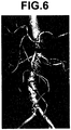
- Figure 5 shows an example pseudo three-dimensional image generated by the image generation apparatus 100 of the present embodiment.
- the three-dimensional morphology of the entire blood vessel is depicted more accurately in comparison with the images generated by performing volume rendering on the same three-dimensional image according to conventional technology shown in Figures 6 and 7 .
- Figure 4 is a flowchart illustrating an operation of the image generation apparatus 100.
- the image obtaining section 11 obtains a three-dimensional image stored in the storage unit 2 (S11).
- the region identification section 13 extracts a whole region representing a blood vessel from the three-dimensional image obtained by the image obtaining section 11 and identifies the extracted region as a whole region (S12).
- the opacity curve setting section 14 sets a base opacity curve to the blood vessel region
- the color map setting section 15 sets a base color map to the blood vessel region (S13).
- the opacity curve setting section 14 or the color map setting section 15 obtains, with respect to each of some pixels obtained by three-dimensionally sampling the pixels in the blood vessel region at a predetermined interval, a subtraction value obtained by subtracting the average value of the pixel values in the blood vessel region from the average value of the pixel values of the adjacent region of a pixel concerned as a shift amount and obtains, with respect to each of pixels other than the sampled some pixels, an estimated value of the shift amount at a pixel concerned by interpolation using the shift amount of each of the two or more sampled pixels located adjacent to the pixel concerned (S14).
- the opacity curve setting section 14 sets, with respect to each of the sampled some pixels, an opacity curve obtained by shifting the base opacity curve by the shift amount determined in step S14 in a pixel value direction as the opacity curve to be applied to the pixel concerned and sets, with respect to each of pixels other than the sampled some pixels, an opacity curve obtained by shifting the base opacity curve by the estimated value determined in step S14 in a pixel value direction as the opacity curve to be applied to the pixel concerned.
- the color map setting section 15 sets, with respect to each of the sampled some pixels, a color map obtained by shifting the base color map by the shift amount determined in step S14 in a pixel value direction as the color map to be applied to the pixel concerned and sets, with respect to each of pixels other than the sampled some pixels, a color map obtained by shifting the base color map by the estimated value determined in step S14 in a pixel value direction as the color map to be applied to the pixel concerned (S15).
- the image generation section 12 generate a pseudo three-dimensional image by performing volume rendering on the three-dimensional image using the opacity curves set by the opacity curve setting section 14 and the color maps set by the color map setting section 15 (S16). Then, the display control section 16 displays the pseudo three-dimensional image generated by the image generation section 12 on the display unit 3 (S17), and the processing is completed.
- the region identification section 13 identifies the whole region representing a blood vessel from a three-dimensional image
- the opacity curve setting section 14 sets a base opacity curve to the identified whole region, and obtains, with respect to each of at least some of the pixels in the whole region, a representative value of pixel values in an adjacent region of a pixel concerned and sets an opacity curve obtained by changing the base opacity curve using the obtained representative value as the opacity curve to be applied to the pixel concerned in volume rendering
- the color map setting section 15 sets a base color map to the identified whole region, obtains, with respect to each of at least some of the pixels in the whole region, a representative value of pixel values in an adjacent region of a pixel concerned, and sets an color map obtained by changing the base color map using the obtained representative value as the color map to be applied to the pixel concerned in volume rendering
- the image generation section 12 generates a pseudo three-dimensional image by performing volume rendering using these opacity curve and color map. This allows an o
- the opacity curve setting section 14 may be a section that obtains, with respect to each of partial regions having a predetermined size and constituting the whole region identified by the region identification section 13, a representative value of pixel values in partial region concerned and sets an opacity curve obtained by modifying the base opacity curve using the obtained representative value as the opacity curve to be applied to the partial region concerned in volume rendering, or a section that obtains, with respect to each of partial regions having a predetermined size and constituting the whole region identified by the region identification section 13, a representative value of pixel values in an adjacent region that includes a partial region concerned and sets an opacity curve obtained by modifying the set base opacity curve using the obtained representative value as the opacity curve to be applied to the partial region concerned in the volume rendering.
- the color map setting section 15 may be a section that obtains, with respect to each of partial regions having a predetermined size and constituting the whole region identified by the region identification section 13, a representative value of pixel values in partial region concerned and sets a color map obtained by modifying the base color map using the obtained representative value as the color map to be applied to the partial region concerned in volume rendering, or a section that obtains, with respect to each of partial regions having a predetermined size and constituting the whole region identified by the region identification section 13, a representative value of pixel values in an adjacent region that includes a partial region concerned and sets color map obtained by modifying the set base color map using the obtained representative value as the color map to be applied to the partial region concerned in the volume rendering.
- the predetermined target object is a blood vessel
- the predetermined target object may be a structure having tubular structure, such as an intestine, a bronchus, and the like, or various organs, such as a heart, a liver, and the like.
- each of the representative value of pixels in the adjacent region and the representative value of pixels in the whole region is an average value
- each of the representative value of pixels in the adjacent region and the representative value of pixels in the whole region may be a mode or median value of the pixels in each region, an average value of pixels of all the pixels in each region which fall in a range of predetermined width of pixel values from the mode or median value of each region, or a mode or median value of pixels of all the pixels in each region which fall in a range of predetermined width of pixel values from the mode or median value of each region.
- the representative value of the pixels in the whole region may be a value of the same type as that of the representative value of the pixels in the adjacent region or a value of different type from that of the representative value of the pixels in the adjacent region.
- the surface of the predetermined target object may also be depicted by the volume rendering.
Landscapes
- Health & Medical Sciences (AREA)
- Life Sciences & Earth Sciences (AREA)
- Engineering & Computer Science (AREA)
- Medical Informatics (AREA)
- Physics & Mathematics (AREA)
- Animal Behavior & Ethology (AREA)
- Veterinary Medicine (AREA)
- Radiology & Medical Imaging (AREA)
- Nuclear Medicine, Radiotherapy & Molecular Imaging (AREA)
- Biomedical Technology (AREA)
- Heart & Thoracic Surgery (AREA)
- Biophysics (AREA)
- Molecular Biology (AREA)
- Surgery (AREA)
- Pathology (AREA)
- General Health & Medical Sciences (AREA)
- Public Health (AREA)
- Computer Graphics (AREA)
- Vascular Medicine (AREA)
- High Energy & Nuclear Physics (AREA)
- Optics & Photonics (AREA)
- General Physics & Mathematics (AREA)
- Theoretical Computer Science (AREA)
- General Engineering & Computer Science (AREA)
- Human Computer Interaction (AREA)
- Dentistry (AREA)
- Oral & Maxillofacial Surgery (AREA)
- Apparatus For Radiation Diagnosis (AREA)
- Image Generation (AREA)
- Measuring And Recording Apparatus For Diagnosis (AREA)
Applications Claiming Priority (2)
| Application Number | Priority Date | Filing Date | Title |
|---|---|---|---|
| JP2012056977A JP5814838B2 (ja) | 2012-03-14 | 2012-03-14 | 画像生成装置、方法及びプログラム |
| PCT/JP2013/001634 WO2013136783A1 (ja) | 2012-03-14 | 2013-03-13 | 画像生成装置、方法及びプログラム |
Publications (3)
| Publication Number | Publication Date |
|---|---|
| EP2827301A1 EP2827301A1 (en) | 2015-01-21 |
| EP2827301A4 EP2827301A4 (en) | 2015-11-25 |
| EP2827301B1 true EP2827301B1 (en) | 2019-08-21 |
Family
ID=49160711
Family Applications (1)
| Application Number | Title | Priority Date | Filing Date |
|---|---|---|---|
| EP13762032.4A Active EP2827301B1 (en) | 2012-03-14 | 2013-03-13 | Image generation device, method, and program |
Country Status (6)
| Country | Link |
|---|---|
| US (1) | US9563978B2 (ja) |
| EP (1) | EP2827301B1 (ja) |
| JP (1) | JP5814838B2 (ja) |
| CN (1) | CN104205172A (ja) |
| IN (1) | IN2014DN07725A (ja) |
| WO (1) | WO2013136783A1 (ja) |
Families Citing this family (12)
| Publication number | Priority date | Publication date | Assignee | Title |
|---|---|---|---|---|
| JP6543099B2 (ja) * | 2015-06-01 | 2019-07-10 | シーフォーシー・メディカル・ソフトウェア,インコーポレーテッド | 情報処理装置、情報処理方法、およびプログラム |
| JP6521250B2 (ja) * | 2015-09-25 | 2019-05-29 | 京セラドキュメントソリューションズ株式会社 | 画像形成装置、色変換プログラムおよび色変換方法 |
| JP6671946B2 (ja) * | 2015-12-11 | 2020-03-25 | キヤノン株式会社 | 情報取得装置、撮像装置及び情報取得方法 |
| US10467798B2 (en) * | 2016-12-19 | 2019-11-05 | Canon Medical Systems Corporation | Rendering a global illumination image from a volumetric medical imaging data set |
| JP7013849B2 (ja) * | 2017-12-22 | 2022-02-01 | 大日本印刷株式会社 | コンピュータプログラム、画像処理装置及び画像処理方法 |
| JP7003635B2 (ja) * | 2017-12-22 | 2022-01-20 | 大日本印刷株式会社 | コンピュータプログラム、画像処理装置及び画像処理方法 |
| JP2019114034A (ja) * | 2017-12-22 | 2019-07-11 | 大日本印刷株式会社 | コンピュータプログラム、画像処理装置、画像処理方法及びボクセルデータ |
| JP6436258B1 (ja) * | 2018-03-27 | 2018-12-12 | 大日本印刷株式会社 | コンピュータプログラム、画像処理装置及び画像処理方法 |
| CN110069310B (zh) * | 2019-04-23 | 2022-04-22 | 北京小米移动软件有限公司 | 切换桌面壁纸的方法、装置及存储介质 |
| CN110211216B (zh) * | 2019-06-14 | 2020-11-03 | 北京理工大学 | 一种基于体绘制不透明度加权的三维图像空域融合方法 |
| US11443476B2 (en) * | 2020-05-27 | 2022-09-13 | Canon Medical Systems Corporation | Image data processing method and apparatus |
| JP2022090453A (ja) * | 2020-12-07 | 2022-06-17 | 富士フイルムヘルスケア株式会社 | 磁気共鳴イメージング装置、画像処理装置および画像処理方法 |
Family Cites Families (5)
| Publication number | Priority date | Publication date | Assignee | Title |
|---|---|---|---|---|
| JP4421203B2 (ja) | 2003-03-20 | 2010-02-24 | 株式会社東芝 | 管腔状構造体の解析処理装置 |
| CN101563706B (zh) * | 2006-07-31 | 2012-10-10 | 皇家飞利浦电子股份有限公司 | 用于为图像数据集的显像创建预设置图的方法、设备 |
| JP2008086658A (ja) * | 2006-10-04 | 2008-04-17 | Fujifilm Corp | 画像表示装置および画像表示プログラム |
| US7990378B2 (en) * | 2007-05-07 | 2011-08-02 | General Electric Company | Methods and apparatus for volume rendering |
| JP5551955B2 (ja) * | 2010-03-31 | 2014-07-16 | 富士フイルム株式会社 | 投影画像生成装置、方法、及びプログラム |
-
2012
- 2012-03-14 JP JP2012056977A patent/JP5814838B2/ja active Active
-
2013
- 2013-03-13 CN CN201380014286.2A patent/CN104205172A/zh active Pending
- 2013-03-13 WO PCT/JP2013/001634 patent/WO2013136783A1/ja active Application Filing
- 2013-03-13 EP EP13762032.4A patent/EP2827301B1/en active Active
-
2014
- 2014-09-11 US US14/483,376 patent/US9563978B2/en active Active
- 2014-09-16 IN IN7725DEN2014 patent/IN2014DN07725A/en unknown
Non-Patent Citations (1)
| Title |
|---|
| None * |
Also Published As
| Publication number | Publication date |
|---|---|
| CN104205172A (zh) | 2014-12-10 |
| US20140375631A1 (en) | 2014-12-25 |
| IN2014DN07725A (ja) | 2015-06-26 |
| JP2013191030A (ja) | 2013-09-26 |
| WO2013136783A1 (ja) | 2013-09-19 |
| EP2827301A1 (en) | 2015-01-21 |
| US9563978B2 (en) | 2017-02-07 |
| JP5814838B2 (ja) | 2015-11-17 |
| EP2827301A4 (en) | 2015-11-25 |
Similar Documents
| Publication | Publication Date | Title |
|---|---|---|
| EP2827301B1 (en) | Image generation device, method, and program | |
| CN110010249B (zh) | 基于视频叠加的增强现实手术导航方法、系统及电子设备 | |
| US7990379B2 (en) | System and method for coronary segmentation and visualization | |
| JP6877868B2 (ja) | 画像処理装置、画像処理方法および画像処理プログラム | |
| US8233684B2 (en) | Systems and methods for automated diagnosis | |
| US8423124B2 (en) | Method and system for spine visualization in 3D medical images | |
| EP2823464B1 (en) | Intelligent landmark selection to improve registration accuracy in multimodal image fusion | |
| USRE35798E (en) | Three-dimensional image processing apparatus | |
| US9025858B2 (en) | Method and apparatus for automatically generating optimal 2-dimensional medical image from 3-dimensional medical image | |
| US8537159B2 (en) | Visualization of voxel data | |
| US8483462B2 (en) | Object centric data reformation with application to rib visualization | |
| JP6133026B2 (ja) | 三次元画像をナビゲートし、セグメント化し、抽出するための方法及びシステム | |
| EP2059165B1 (en) | Detection and localization of vascular occlusion from angiography data | |
| US8068655B2 (en) | Method and system for vessel enhancement and artifact reduction in TOF MR angiography of brain | |
| CN107111875B (zh) | 用于多模态自动配准的反馈 | |
| EP2878278B1 (en) | Surgical operation support device, method and program | |
| US20170360396A1 (en) | Ultrasound imaging apparatus and method for segmenting anatomical objects | |
| CA2719885C (en) | Method and device for segmenting medical image data | |
| Wang et al. | A fast 3D brain extraction and visualization framework using active contour and modern OpenGL pipelines | |
| Kiraly et al. | 3D human airway segmentation for virtual bronchoscopy | |
| CN109313803B (zh) | 一种用于映射对象的身体的至少部分的图像中的结构的至少部分的方法和装置 | |
| CN116051553B (zh) | 一种在三维医学模型内部进行标记的方法和装置 | |
| US20120098832A1 (en) | Image reconstruction | |
| EP2633499B1 (en) | Volume visualisation based on distance | |
| US20150199840A1 (en) | Shape data generation method and apparatus |
Legal Events
| Date | Code | Title | Description |
|---|---|---|---|
| PUAI | Public reference made under article 153(3) epc to a published international application that has entered the european phase |
Free format text: ORIGINAL CODE: 0009012 |
|
| 17P | Request for examination filed |
Effective date: 20140919 |
|
| AK | Designated contracting states |
Kind code of ref document: A1 Designated state(s): AL AT BE BG CH CY CZ DE DK EE ES FI FR GB GR HR HU IE IS IT LI LT LU LV MC MK MT NL NO PL PT RO RS SE SI SK SM TR |
|
| AX | Request for extension of the european patent |
Extension state: BA ME |
|
| DAX | Request for extension of the european patent (deleted) | ||
| RA4 | Supplementary search report drawn up and despatched (corrected) |
Effective date: 20151022 |
|
| RIC1 | Information provided on ipc code assigned before grant |
Ipc: A61B 6/03 20060101ALI20151016BHEP Ipc: A61B 5/00 20060101ALI20151016BHEP Ipc: G06T 15/08 20110101AFI20151016BHEP |
|
| STAA | Information on the status of an ep patent application or granted ep patent |
Free format text: STATUS: EXAMINATION IS IN PROGRESS |
|
| 17Q | First examination report despatched |
Effective date: 20180809 |
|
| REG | Reference to a national code |
Ref country code: DE Ref legal event code: R079 Ref document number: 602013059474 Country of ref document: DE Free format text: PREVIOUS MAIN CLASS: G06T0015080000 Ipc: A61B0006000000 |
|
| GRAP | Despatch of communication of intention to grant a patent |
Free format text: ORIGINAL CODE: EPIDOSNIGR1 |
|
| STAA | Information on the status of an ep patent application or granted ep patent |
Free format text: STATUS: GRANT OF PATENT IS INTENDED |
|
| RIC1 | Information provided on ipc code assigned before grant |
Ipc: A61B 8/08 20060101ALI20190219BHEP Ipc: G06T 15/08 20110101ALI20190219BHEP Ipc: A61B 5/00 20060101ALI20190219BHEP Ipc: A61B 6/00 20060101AFI20190219BHEP Ipc: A61B 8/00 20060101ALI20190219BHEP |
|
| INTG | Intention to grant announced |
Effective date: 20190308 |
|
| GRAS | Grant fee paid |
Free format text: ORIGINAL CODE: EPIDOSNIGR3 |
|
| GRAA | (expected) grant |
Free format text: ORIGINAL CODE: 0009210 |
|
| STAA | Information on the status of an ep patent application or granted ep patent |
Free format text: STATUS: THE PATENT HAS BEEN GRANTED |
|
| AK | Designated contracting states |
Kind code of ref document: B1 Designated state(s): AL AT BE BG CH CY CZ DE DK EE ES FI FR GB GR HR HU IE IS IT LI LT LU LV MC MK MT NL NO PL PT RO RS SE SI SK SM TR |
|
| REG | Reference to a national code |
Ref country code: GB Ref legal event code: FG4D |
|
| REG | Reference to a national code |
Ref country code: CH Ref legal event code: EP |
|
| REG | Reference to a national code |
Ref country code: DE Ref legal event code: R096 Ref document number: 602013059474 Country of ref document: DE |
|
| REG | Reference to a national code |
Ref country code: AT Ref legal event code: REF Ref document number: 1168760 Country of ref document: AT Kind code of ref document: T Effective date: 20190915 |
|
| REG | Reference to a national code |
Ref country code: IE Ref legal event code: FG4D |
|
| REG | Reference to a national code |
Ref country code: LT Ref legal event code: MG4D |
|
| REG | Reference to a national code |
Ref country code: NL Ref legal event code: MP Effective date: 20190821 |
|
| PG25 | Lapsed in a contracting state [announced via postgrant information from national office to epo] |
Ref country code: HR Free format text: LAPSE BECAUSE OF FAILURE TO SUBMIT A TRANSLATION OF THE DESCRIPTION OR TO PAY THE FEE WITHIN THE PRESCRIBED TIME-LIMIT Effective date: 20190821 Ref country code: LT Free format text: LAPSE BECAUSE OF FAILURE TO SUBMIT A TRANSLATION OF THE DESCRIPTION OR TO PAY THE FEE WITHIN THE PRESCRIBED TIME-LIMIT Effective date: 20190821 Ref country code: SE Free format text: LAPSE BECAUSE OF FAILURE TO SUBMIT A TRANSLATION OF THE DESCRIPTION OR TO PAY THE FEE WITHIN THE PRESCRIBED TIME-LIMIT Effective date: 20190821 Ref country code: BG Free format text: LAPSE BECAUSE OF FAILURE TO SUBMIT A TRANSLATION OF THE DESCRIPTION OR TO PAY THE FEE WITHIN THE PRESCRIBED TIME-LIMIT Effective date: 20191121 Ref country code: NL Free format text: LAPSE BECAUSE OF FAILURE TO SUBMIT A TRANSLATION OF THE DESCRIPTION OR TO PAY THE FEE WITHIN THE PRESCRIBED TIME-LIMIT Effective date: 20190821 Ref country code: PT Free format text: LAPSE BECAUSE OF FAILURE TO SUBMIT A TRANSLATION OF THE DESCRIPTION OR TO PAY THE FEE WITHIN THE PRESCRIBED TIME-LIMIT Effective date: 20191223 Ref country code: FI Free format text: LAPSE BECAUSE OF FAILURE TO SUBMIT A TRANSLATION OF THE DESCRIPTION OR TO PAY THE FEE WITHIN THE PRESCRIBED TIME-LIMIT Effective date: 20190821 Ref country code: NO Free format text: LAPSE BECAUSE OF FAILURE TO SUBMIT A TRANSLATION OF THE DESCRIPTION OR TO PAY THE FEE WITHIN THE PRESCRIBED TIME-LIMIT Effective date: 20191121 |
|
| PG25 | Lapsed in a contracting state [announced via postgrant information from national office to epo] |
Ref country code: IS Free format text: LAPSE BECAUSE OF FAILURE TO SUBMIT A TRANSLATION OF THE DESCRIPTION OR TO PAY THE FEE WITHIN THE PRESCRIBED TIME-LIMIT Effective date: 20191221 Ref country code: RS Free format text: LAPSE BECAUSE OF FAILURE TO SUBMIT A TRANSLATION OF THE DESCRIPTION OR TO PAY THE FEE WITHIN THE PRESCRIBED TIME-LIMIT Effective date: 20190821 Ref country code: LV Free format text: LAPSE BECAUSE OF FAILURE TO SUBMIT A TRANSLATION OF THE DESCRIPTION OR TO PAY THE FEE WITHIN THE PRESCRIBED TIME-LIMIT Effective date: 20190821 Ref country code: ES Free format text: LAPSE BECAUSE OF FAILURE TO SUBMIT A TRANSLATION OF THE DESCRIPTION OR TO PAY THE FEE WITHIN THE PRESCRIBED TIME-LIMIT Effective date: 20190821 Ref country code: GR Free format text: LAPSE BECAUSE OF FAILURE TO SUBMIT A TRANSLATION OF THE DESCRIPTION OR TO PAY THE FEE WITHIN THE PRESCRIBED TIME-LIMIT Effective date: 20191122 Ref country code: AL Free format text: LAPSE BECAUSE OF FAILURE TO SUBMIT A TRANSLATION OF THE DESCRIPTION OR TO PAY THE FEE WITHIN THE PRESCRIBED TIME-LIMIT Effective date: 20190821 |
|
| REG | Reference to a national code |
Ref country code: AT Ref legal event code: MK05 Ref document number: 1168760 Country of ref document: AT Kind code of ref document: T Effective date: 20190821 |
|
| PG25 | Lapsed in a contracting state [announced via postgrant information from national office to epo] |
Ref country code: TR Free format text: LAPSE BECAUSE OF FAILURE TO SUBMIT A TRANSLATION OF THE DESCRIPTION OR TO PAY THE FEE WITHIN THE PRESCRIBED TIME-LIMIT Effective date: 20190821 |
|
| PG25 | Lapsed in a contracting state [announced via postgrant information from national office to epo] |
Ref country code: AT Free format text: LAPSE BECAUSE OF FAILURE TO SUBMIT A TRANSLATION OF THE DESCRIPTION OR TO PAY THE FEE WITHIN THE PRESCRIBED TIME-LIMIT Effective date: 20190821 Ref country code: PL Free format text: LAPSE BECAUSE OF FAILURE TO SUBMIT A TRANSLATION OF THE DESCRIPTION OR TO PAY THE FEE WITHIN THE PRESCRIBED TIME-LIMIT Effective date: 20190821 Ref country code: DK Free format text: LAPSE BECAUSE OF FAILURE TO SUBMIT A TRANSLATION OF THE DESCRIPTION OR TO PAY THE FEE WITHIN THE PRESCRIBED TIME-LIMIT Effective date: 20190821 Ref country code: EE Free format text: LAPSE BECAUSE OF FAILURE TO SUBMIT A TRANSLATION OF THE DESCRIPTION OR TO PAY THE FEE WITHIN THE PRESCRIBED TIME-LIMIT Effective date: 20190821 Ref country code: RO Free format text: LAPSE BECAUSE OF FAILURE TO SUBMIT A TRANSLATION OF THE DESCRIPTION OR TO PAY THE FEE WITHIN THE PRESCRIBED TIME-LIMIT Effective date: 20190821 Ref country code: IT Free format text: LAPSE BECAUSE OF FAILURE TO SUBMIT A TRANSLATION OF THE DESCRIPTION OR TO PAY THE FEE WITHIN THE PRESCRIBED TIME-LIMIT Effective date: 20190821 |
|
| PG25 | Lapsed in a contracting state [announced via postgrant information from national office to epo] |
Ref country code: SM Free format text: LAPSE BECAUSE OF FAILURE TO SUBMIT A TRANSLATION OF THE DESCRIPTION OR TO PAY THE FEE WITHIN THE PRESCRIBED TIME-LIMIT Effective date: 20190821 Ref country code: SK Free format text: LAPSE BECAUSE OF FAILURE TO SUBMIT A TRANSLATION OF THE DESCRIPTION OR TO PAY THE FEE WITHIN THE PRESCRIBED TIME-LIMIT Effective date: 20190821 Ref country code: IS Free format text: LAPSE BECAUSE OF FAILURE TO SUBMIT A TRANSLATION OF THE DESCRIPTION OR TO PAY THE FEE WITHIN THE PRESCRIBED TIME-LIMIT Effective date: 20200224 Ref country code: CZ Free format text: LAPSE BECAUSE OF FAILURE TO SUBMIT A TRANSLATION OF THE DESCRIPTION OR TO PAY THE FEE WITHIN THE PRESCRIBED TIME-LIMIT Effective date: 20190821 |
|
| REG | Reference to a national code |
Ref country code: DE Ref legal event code: R097 Ref document number: 602013059474 Country of ref document: DE |
|
| PLBE | No opposition filed within time limit |
Free format text: ORIGINAL CODE: 0009261 |
|
| STAA | Information on the status of an ep patent application or granted ep patent |
Free format text: STATUS: NO OPPOSITION FILED WITHIN TIME LIMIT |
|
| PG2D | Information on lapse in contracting state deleted |
Ref country code: IS |
|
| 26N | No opposition filed |
Effective date: 20200603 |
|
| PG25 | Lapsed in a contracting state [announced via postgrant information from national office to epo] |
Ref country code: SI Free format text: LAPSE BECAUSE OF FAILURE TO SUBMIT A TRANSLATION OF THE DESCRIPTION OR TO PAY THE FEE WITHIN THE PRESCRIBED TIME-LIMIT Effective date: 20190821 |
|
| PG25 | Lapsed in a contracting state [announced via postgrant information from national office to epo] |
Ref country code: MC Free format text: LAPSE BECAUSE OF FAILURE TO SUBMIT A TRANSLATION OF THE DESCRIPTION OR TO PAY THE FEE WITHIN THE PRESCRIBED TIME-LIMIT Effective date: 20190821 |
|
| REG | Reference to a national code |
Ref country code: CH Ref legal event code: PL |
|
| REG | Reference to a national code |
Ref country code: BE Ref legal event code: MM Effective date: 20200331 |
|
| PG25 | Lapsed in a contracting state [announced via postgrant information from national office to epo] |
Ref country code: LU Free format text: LAPSE BECAUSE OF NON-PAYMENT OF DUE FEES Effective date: 20200313 |
|
| PG25 | Lapsed in a contracting state [announced via postgrant information from national office to epo] |
Ref country code: FR Free format text: LAPSE BECAUSE OF NON-PAYMENT OF DUE FEES Effective date: 20200331 Ref country code: IE Free format text: LAPSE BECAUSE OF NON-PAYMENT OF DUE FEES Effective date: 20200313 Ref country code: CH Free format text: LAPSE BECAUSE OF NON-PAYMENT OF DUE FEES Effective date: 20200331 Ref country code: LI Free format text: LAPSE BECAUSE OF NON-PAYMENT OF DUE FEES Effective date: 20200331 |
|
| PG25 | Lapsed in a contracting state [announced via postgrant information from national office to epo] |
Ref country code: BE Free format text: LAPSE BECAUSE OF NON-PAYMENT OF DUE FEES Effective date: 20200331 |
|
| GBPC | Gb: european patent ceased through non-payment of renewal fee |
Effective date: 20200313 |
|
| PG25 | Lapsed in a contracting state [announced via postgrant information from national office to epo] |
Ref country code: GB Free format text: LAPSE BECAUSE OF NON-PAYMENT OF DUE FEES Effective date: 20200313 |
|
| PG25 | Lapsed in a contracting state [announced via postgrant information from national office to epo] |
Ref country code: MT Free format text: LAPSE BECAUSE OF FAILURE TO SUBMIT A TRANSLATION OF THE DESCRIPTION OR TO PAY THE FEE WITHIN THE PRESCRIBED TIME-LIMIT Effective date: 20190821 Ref country code: CY Free format text: LAPSE BECAUSE OF FAILURE TO SUBMIT A TRANSLATION OF THE DESCRIPTION OR TO PAY THE FEE WITHIN THE PRESCRIBED TIME-LIMIT Effective date: 20190821 |
|
| PG25 | Lapsed in a contracting state [announced via postgrant information from national office to epo] |
Ref country code: MK Free format text: LAPSE BECAUSE OF FAILURE TO SUBMIT A TRANSLATION OF THE DESCRIPTION OR TO PAY THE FEE WITHIN THE PRESCRIBED TIME-LIMIT Effective date: 20190821 |
|
| P01 | Opt-out of the competence of the unified patent court (upc) registered |
Effective date: 20230515 |
|
| PGFP | Annual fee paid to national office [announced via postgrant information from national office to epo] |
Ref country code: DE Payment date: 20240130 Year of fee payment: 12 |