EP2827283A1 - Light emitting apparatus, manufacturing method of light emitting apparatus, light receiving and emitting apparatus, and electronic equipment - Google Patents
Light emitting apparatus, manufacturing method of light emitting apparatus, light receiving and emitting apparatus, and electronic equipment Download PDFInfo
- Publication number
- EP2827283A1 EP2827283A1 EP14177242.6A EP14177242A EP2827283A1 EP 2827283 A1 EP2827283 A1 EP 2827283A1 EP 14177242 A EP14177242 A EP 14177242A EP 2827283 A1 EP2827283 A1 EP 2827283A1
- Authority
- EP
- European Patent Office
- Prior art keywords
- light emitting
- light
- section
- optical filter
- layer
- Prior art date
- Legal status (The legal status is an assumption and is not a legal conclusion. Google has not performed a legal analysis and makes no representation as to the accuracy of the status listed.)
- Granted
Links
Images








Classifications
-
- G—PHYSICS
- G06—COMPUTING OR CALCULATING; COUNTING
- G06V—IMAGE OR VIDEO RECOGNITION OR UNDERSTANDING
- G06V40/00—Recognition of biometric, human-related or animal-related patterns in image or video data
- G06V40/10—Human or animal bodies, e.g. vehicle occupants or pedestrians; Body parts, e.g. hands
- G06V40/12—Fingerprints or palmprints
- G06V40/13—Sensors therefor
- G06V40/1318—Sensors therefor using electro-optical elements or layers, e.g. electroluminescent sensing
-
- H—ELECTRICITY
- H10—SEMICONDUCTOR DEVICES; ELECTRIC SOLID-STATE DEVICES NOT OTHERWISE PROVIDED FOR
- H10H—INORGANIC LIGHT-EMITTING SEMICONDUCTOR DEVICES HAVING POTENTIAL BARRIERS
- H10H20/00—Individual inorganic light-emitting semiconductor devices having potential barriers, e.g. light-emitting diodes [LED]
- H10H20/80—Constructional details
- H10H20/83—Electrodes
- H10H20/832—Electrodes characterised by their material
- H10H20/835—Reflective materials
-
- G—PHYSICS
- G06—COMPUTING OR CALCULATING; COUNTING
- G06V—IMAGE OR VIDEO RECOGNITION OR UNDERSTANDING
- G06V40/00—Recognition of biometric, human-related or animal-related patterns in image or video data
- G06V40/10—Human or animal bodies, e.g. vehicle occupants or pedestrians; Body parts, e.g. hands
- G06V40/12—Fingerprints or palmprints
- G06V40/13—Sensors therefor
- G06V40/1324—Sensors therefor by using geometrical optics, e.g. using prisms
-
- H—ELECTRICITY
- H10—SEMICONDUCTOR DEVICES; ELECTRIC SOLID-STATE DEVICES NOT OTHERWISE PROVIDED FOR
- H10F—INORGANIC SEMICONDUCTOR DEVICES SENSITIVE TO INFRARED RADIATION, LIGHT, ELECTROMAGNETIC RADIATION OF SHORTER WAVELENGTH OR CORPUSCULAR RADIATION
- H10F55/00—Radiation-sensitive semiconductor devices covered by groups H10F10/00, H10F19/00 or H10F30/00 being structurally associated with electric light sources and electrically or optically coupled thereto
- H10F55/20—Radiation-sensitive semiconductor devices covered by groups H10F10/00, H10F19/00 or H10F30/00 being structurally associated with electric light sources and electrically or optically coupled thereto wherein the electric light source controls the radiation-sensitive semiconductor devices, e.g. optocouplers
-
- H—ELECTRICITY
- H10—SEMICONDUCTOR DEVICES; ELECTRIC SOLID-STATE DEVICES NOT OTHERWISE PROVIDED FOR
- H10F—INORGANIC SEMICONDUCTOR DEVICES SENSITIVE TO INFRARED RADIATION, LIGHT, ELECTROMAGNETIC RADIATION OF SHORTER WAVELENGTH OR CORPUSCULAR RADIATION
- H10F71/00—Manufacture or treatment of devices covered by this subclass
-
- H—ELECTRICITY
- H10—SEMICONDUCTOR DEVICES; ELECTRIC SOLID-STATE DEVICES NOT OTHERWISE PROVIDED FOR
- H10H—INORGANIC LIGHT-EMITTING SEMICONDUCTOR DEVICES HAVING POTENTIAL BARRIERS
- H10H20/00—Individual inorganic light-emitting semiconductor devices having potential barriers, e.g. light-emitting diodes [LED]
- H10H20/01—Manufacture or treatment
-
- H—ELECTRICITY
- H10—SEMICONDUCTOR DEVICES; ELECTRIC SOLID-STATE DEVICES NOT OTHERWISE PROVIDED FOR
- H10H—INORGANIC LIGHT-EMITTING SEMICONDUCTOR DEVICES HAVING POTENTIAL BARRIERS
- H10H20/00—Individual inorganic light-emitting semiconductor devices having potential barriers, e.g. light-emitting diodes [LED]
- H10H20/80—Constructional details
- H10H20/83—Electrodes
- H10H20/832—Electrodes characterised by their material
- H10H20/833—Transparent materials
-
- G—PHYSICS
- G06—COMPUTING OR CALCULATING; COUNTING
- G06V—IMAGE OR VIDEO RECOGNITION OR UNDERSTANDING
- G06V40/00—Recognition of biometric, human-related or animal-related patterns in image or video data
- G06V40/10—Human or animal bodies, e.g. vehicle occupants or pedestrians; Body parts, e.g. hands
- G06V40/14—Vascular patterns
Definitions
- Several aspects of the present invention relate to a light emitting apparatus, a manufacturing method of a light emitting apparatus, a light receiving and emitting apparatus in which the light emitting apparatus is used as a lighting apparatus, and electronic equipment provided with the light receiving and emitting apparatus.
- An optical apparatus in which one or more electromagnetic wave emission elements and one or more electromagnetic wave detection elements are provided on a surface of a CMOS substrate as a light receiving and emitting apparatus provided with a light emitting apparatus and at least one of the electromagnetic wave detection elements is an element capable of being manufactured by the CMOS technology, is well known (see JP-A 2008-42175 (Patent Document 1), for example).
- the electromagnetic wave emission element includes an organic light emitting diode or a light emitting diode
- the electromagnetic wave detection element includes a photodiode or a CMOS sensor.
- the electromagnetic wave emission elements and the electromagnetic wave detection elements are evenly distributed and arranged on the substrate made of silicon. Further, as a wavelength of the electromagnetic wave, it includes a visible light wavelength or a near infrared wavelength.
- Such optical apparatus includes a display in which three organic light emitting diodes, which emit wavelengths of a red light, a green light, and a blue light, are adjacently arranged.
- the electromagnetic wave detection element is provided between the three organic light emitting diodes.
- Patent Document 1 When the optical apparatus of the aforementioned Patent Document 1 is used as an imaging means, a subject is illuminated by the light as an electromagnetic wave emitted from the electromagnetic wave emission element, and the reflected light from the subject is received in the electromagnetic wave detection element.
- it is not only used to obtain an image of the subject by receiving the light that is reflected on the surface of the subject, but also, it attempts to be used in, for example, a biometric authentication, or in the medical field, to obtain a shape of a blood vessel in the body, or biometric information such as components in the blood (e.g., hemoglobin) by irradiating the light to a human body as a subject.
- the electromagnetic wave detection element of the aforementioned optical apparatus receives both the light reflected from the surface of the subject and the light reflected inside part of the subject. Therefore, it was considered to correspondently provide an optical filter, which selectively transmits only a desired wavelength of the electromagnetic wave (light) by eliminating an unnecessary wavelength of the electromagnetic wave (light) other than the desired wavelength that accurately reflects the biometric information, in the electromagnetic wave detection element.
- an optical filter which selectively transmits only a desired wavelength of the electromagnetic wave (light) by eliminating an unnecessary wavelength of the electromagnetic wave (light) other than the desired wavelength that accurately reflects the biometric information, in the electromagnetic wave detection element.
- the structure of the aforementioned optical apparatus becomes complicated.
- the present invention was made to address at least a part of the aforementioned objects, and is capable of realizing the following embodiments or applied examples.
- a light emitting apparatus is provided with a translucent substrate, and a light emitting section and an optical filter section arranged in a first region of the substrate when viewed in a normal direction of a first surface of the substrate.
- the light emitting section has a laminate structure that includes, on the first surface of the substrate, a dielectric multilayer film, a first electrode, a functional layer with a light emitting layer, and a second electrode having semi-transmissive reflectivity.
- the optical filter section has a laminate structure that includes, on the first surface of the substrate, the dielectric multilayer film, the functional layer, and the second electrode. The dielectric multilayer film and the functional layer extend over the first region.
- the light emitting section and the optical filter section share the dielectric multilayer film, the functional layer, and the second electrode. Therefore, in comparison with that the light emitting section and the optical filter section are formed on the substrate by using different members respectively, the light emitting apparatus, which is provided with a simple formation and structure of the light emitting section and the optical filter section, can be provided.
- the light emitting section can have a reflection layer that is disposed between the first surface of the substrate and the dielectric multilayer film.
- a first optical resonance structure is formed between the reflection layer and the second electrode.
- a second optical resonance structure is formed between the dielectric multilayer film of the optical filter section and the second electrode.
- the optical resonance structure is respectively formed in the light emitting section and the optical filter section so that the light in which the light intensity has been enhanced can be extracted in the resonance wavelength from the light emitting section. Further, the light of the resonance wavelength can be selectively transmitted in the optical filter section.
- the optical filter section can be configured to transmit light in a part of a wavelength range of light emitted from the light emitting section.
- the optical filter section can include a transparent layer that has the same thickness of the first electrode and is located in the same layer level with the first electrode.
- the second optical resonance structure has the same resonance length of the first optical resonance structure, optically. That is, the light with the wavelength being close to the resonance wavelength in the light emitting section can be selectively transmitted in the optical filter section.
- the optical filter section can include a transparent layer that is made of the same conducting film as the first electrode and is located in the same layer level with the first electrode.
- the first electrode has a film thickness that is different from that of the transparent layer.
- the resonance length of the second optical resonance structure and the resonance length of the first optical resonance structure are different. That is, the light with the wavelength being different from the resonance wavelength in the light emitting section can be selectively transmitted in the optical filter section.
- the optical filter section is free of a transparent layer that is made of the same conducting film as the first electrode and is located in the same layer level with the first electrode.
- the second optical resonance structure optically shortens the resonance length, which corresponds to the optical length of the first electrode, than the first optical resonance structure. That is, the light with the wavelength shorter than the resonance wavelength in the light emitting section can be selectively transmitted in the optical filter section.
- the optical filter section can be configured to transmit fluorescent excited by light emission in the light emitting section.
- a distance d1 from a center of the light emitting section to tan outer edge of the light emitting section measured in a direction directing toward a center of the optical filter section from the center of the light emitting section can satisfy a relationship of 5 ⁇ m ⁇ d1 ⁇ 0. 7mm.
- the light emitting section when the distance d1 from the center to the outer edge of the light emitting section is more than or equal to 5 ⁇ m, the light emitting section can be arranged so as to avoid that a circuit element or a wire for driving the light emitting section is entered in the optical filter section. Further, by defining that the distance d1 from the center to the outer edge of the light emitting section is less than or equal to 0.7mm, when the light emitting apparatus is used for the light receiving and emitting apparatus which is capable of obtaining, for example, various biometric information, the biometric information can be obtained as high-definition image information.
- the light emitting section can be configured to emit near-infrared light.
- the near-infrared light can illuminate inside of a living body in comparison with the visible light so that it can be used as a lighting apparatus that is capable of obtaining biometric information related to, for example, blood vessel, blood, etc.
- a plurality of light emitting sections arranged in the first region of the substrate can be further provided.
- the light emitting sections have light emitting wavelength ranges that are shifted relative to each other.
- the utilization range of the light emitting apparatus can be expanded.
- a plurality of optical filter sections arranged in the first region of the substrate can be further provide.
- the optical filter sections have wavelength ranges of transmitting light that are shifted relative to each other.
- the utilization range of the light emitting apparatus can be expanded.
- the dielectric multilayer film can have a laminate structure that includes the first dielectric film having a first refractive index and the second dielectric film having a second refractive index that is larger than the first refractive index.
- the second dielectric film can be made of amorphous silicon.
- the transmittance of the light with the visible light wavelength range that is transmitted the optical filter section can be reduced.
- the second electrode can include a layer made of alloy that includes Ag.
- the second electrode having both light permeability and light reflectivity can be easily provided.
- the first electrode can extend along a first direction
- the second electrode can extend along a second direction that intersects with the first electrode.
- the light emitting section can include a part of the first electrode that extends along the first direction
- the optical filter section can include a part of the second electrode that does not overlap with the part of the first electrode.
- the light emitting apparatus with a passive system in which the circuit structure for emitting the light in the light emitting section is simple can be provided.
- a manufacturing method of a light emitting apparatus is a manufacturing method of a light emitting apparatus including a translucent substrate, and a light emitting section and an optical filer section that are arranged in a first region of the substrate when viewed in a normal direction of a first surface of the substrate.
- the manufacturing method includes forming a dielectric multilayer film over the first region of the substrate, forming a first electrode on the dielectric multilayer film included in the light emitting section, forming a functional layer with a light emitting layer over the first electrode and the dielectric multilayer film included in the optical filter section, and forming a second electrode having semi-transmissive reflectivity on the functional layer over the first region of the substrate.
- the light emitting section and the optical filter section share the dielectric multilayer film, the functional layer, and the second electrode formed in the entire first region so that in comparison with a case that the light emitting section and the optical filter section are formed on the substrate by using respective separate members, the light emitting apparatus provided with the light emitting section and the optical filter section can be manufactured in a simple process.
- forming a reflection layer between the first surface of the substrate and the dielectric multilayer film included in the light emitting section can be further included.
- a first optical resonance structure is formed between the reflection layer and the second electrode included in the light emitting section.
- a second optical resonance structure is formed between the dielectric multilayer film and the second electrode included in the optical filter section.
- the optical resonance structure is formed in the light emitting section and the optical filter section, respectively so that it is possible to obtain the light with a specific resonance wavelength from the light emitting section, and further, the light emitting apparatus capable of selectively transmitting the light with the specific resonance wavelength in the optical filter section can be manufactured.
- a light receiving and emitting apparatus has the light emitting apparatus described in the aforementioned applied example, and a light receiving section disposed in a position overlapping the optical filter section in an opposite side of the first surface of the substrate.
- the light emitting apparatus has a simple formation and structure so that a compact light receiving and emitting apparatus can be provided. Therefore, the light receiving and emitting apparatus can be used as an imaging apparatus capable of obtaining the information of a subject.
- a microlens disposed between the optical filter section and the light receiving section can be further provided.
- the light from the subject that was illuminated by the light emitting apparatus can be efficiently collected to the light receiving element by the microlens so that a light image can be obtained.
- a light shielding film having an opening section that is disposed between the microlens and the light receiving section can be further provided.
- the light other than the necessary light is shielded by the light shielding film so that only the necessary light can be incident on the light receiving element through the opening section.
- An electronic equipment according to the present applied example includes the light receiving and emitting apparatus described in the aforementioned applied example.
- a biometric authentication apparatus as an example of electronic equipment in which a light receiving and emitting apparatus provided with a light emitting apparatus of the present invention is applied will be described in reference to Fig. 1, Fig. 2A and Fig. 2B.
- Fig. 1 is a block diagram showing a mechanical and electrical configuration of a biometric authentication apparatus
- Fig. 2A is a perspective view of the light receiving and emitting apparatus
- Fig. 2B is a schematic cross-sectional diagram showing a configuration of the light receiving and emitting apparatus.
- a biometric authentication apparatus 100 as the electronic equipment of the present embodiment is an apparatus to perform identity authentication by taking a vein image of a finger F as a living body (subject), and is provided with a light receiving and emitting apparatus 150, a memory section 80, an output section 90, and a control section 70 that integrates and controls these sections.
- the light receiving and emitting apparatus 150 is provided with a cover glass 60, a light emitting apparatus 110 that illuminates the finger F, and a light receiving apparatus 140.
- the light emitting apparatus 110 is arranged between the cover glass 60 and the light receiving apparatus 140.
- the cover glass 60 is a protection cover made of glass that covers at least the light emission region of the light emitting apparatus 110.
- the finger F e.g., index finger of the right hand
- the cover glass 60 is a protection cover made of glass that covers at least the light emission region of the light emitting apparatus 110.
- the finger F e.g., index finger of the right hand
- the cover glass 60 is placed on the cover glass 60.
- the near-infrared light IL is irradiated as an illumination light from the light emitting section provided on the translucent substrate and illuminates the finger F.
- the wavelength range of the near-infrared light IL is, for example, 700nm to 1500nm.
- the near-infrared light IL irradiated from the light emitting section irradiates to the finger F from the lower side of the cover glass 60, and when it reaches to the inside of the finger F, it scatters and a part of the light as a reflected light RL transmits the substrate of the light emitting apparatus 110 and goes toward the light receiving apparatus 140.
- the reduced hemoglobin (deoxygenated hemoglobin) flowing in veins has the property of absorbing the near-infrared light IL. Therefore, when the near-infrared light IL is irradiated and an image of the finger F is taken, the vein segment under the skin of the finger F is taken darker in comparison with the surrounding tissue.
- the light receiving apparatus 140 is an image sensor for near-infrared light, and is provided with a plurality of light receiving sections 142 (see Fig. 2B ) arranged on the substrate 141. Each light receiving section 142 convers the incident light (the reflected light RL from the finger F) to an electrical signal (light receiving signal) having a signal level in response to the amount of light.
- the memory section 80 is a nonvolatile memory such as a flash memory, a hard disk, etc., and stores a vein image (vein pattern) of the finger F (e.g., index finger of the right hand) that has already been registered as a master vein image for identity authentication (vein pattern).
- the control section 70 is provided with a CPU or a RAM, and controls the lighting on or the lighting off of the light emitting apparatus 110. Further, the control section 70 reads out a receiving signal from each light receiving section 142 provided in the light receiving apparatus 140, and generates a vein image (vein pattern) of the finger F based on the receiving signal per one frame (per imaging region) that has been read.
- control section 70 verifies the generated vein image (vein pattern) with the master vein image (vein pattern) that has been registered in the memory section 80, and performs identity authentication. For example, the control section 70 compares the characteristics (e.g., the numbers or the positions of branching of veins) of two vein images (vein patterns), and when it is more than or equal to the predetermined threshold values, the person who placed the finger F on the cover glass 60 is authenticated as the identical person that the master vein image (vein pattern) has been registered in the memory section 80.
- the output section 90 is, for example, a display section or a voice informing section, and the authentication result is notified by display or voice.
- the light receiving and emitting apparatus 150 of the present embodiment has a configuration that laminates in the order of the light receiving apparatus 140, a pinhole substrate 130, a microlens array 120, the light emitting apparatus 110, and the cover glass 60.
- the light receiving and emitting apparatus 150 is an apparatus that takes a vein image (vein pattern) as the biometric information of the finger F in order to identify an individual of the finger F as the living body placed on the cover glass 60.
- the surface of the cover glass 60 on which the finger F is placed is defined by the X-direction and the Y-direction.
- a direction from the light receiving apparatus 140 to the cover glass 60 is defined as the Z-direction.
- the finger F is placed on the cover glass 60 along the Y-direction.
- a guideline, etc. for guiding the finger F may be printed on the surface of the cover glass 60.
- the light emitting apparatus 110 and the light receiving apparatus 140 are laminated within a planar surface that is defined by the X-direction and the Y-direction so that in comparison with the case that the light emitting apparatus 110 for illuminating a subject is separately provided, a compact light receiving and emitting apparatus 150 can be provided.
- the light emitting apparatus 110 is provided with a translucent substrate 111, a light emitting section 30 arranged on the first surface 111a of the substrate 111, and an optical filter section 50.
- the light emitting section 30 and the optical filter section 50 are two-dimensionally adjacent to each other on the first surface 111a, and a plurality of the light emitting sections and the optical filter sections are respectively arranged.
- the near-infrared light IL is irradiated from the light emitting section 30 to the cover glass 60 side (that is, the Z-direction).
- the IL is not only reflected on the surface of the finger F, but also entering and scattering the inside of the finger F. Further, it may not be only the reflected light RL of the near-infrared light IL, but there is a possibility to mix with external light depending on the environment where the light receiving and emitting apparatus 150 is existed. To perform the individual identification accurately, it is desired to obtain a vivid vein image (vein pattern) of the finger F.
- a specific wavelength of the light which is capable of performing the imaging for a vein image (vein pattern) without unnecessary wavelength of the light, is preferably guided to the light receiving apparatus 140.
- the optical filter section 50 is configured so that in the reflected light RL which was incident to the optical filter section 50, the transmittance of the specific wavelength of the light, which is capable of performing the imaging for a vein image (vein pattern), is higher than the transmittance of the light other than the specific wavelength.
- the microlens array 120 and the pinhole substrate 130 are arranged between the light emitting apparatus 110 and the light receiving apparatus 140.
- the microlens array 120 is provided with a translucent substrate 121, and a plurality of microlenses 122 provided on the surface 121b which is opposite side with respect to the surface 121 a in the light emitting apparatus 110 side of the substrate 121.
- the microlenses 122 are formed on the surface 121b of the substrate 121 corresponding to the arrangement of the optical filter section 50 of the light emitting apparatus 110.
- the light transmitted through the optical filter section 50 is collected by the microlenses 122 and guides to the light receiving section 142 of the light receiving apparatus 140.
- the arrangement of the microlens array 120 is not limited to this, and it may be arranged between the cover glass 60 and the light emitting apparatus 110.
- the pinhole substrate 130 is provided with a translucent substrate 131, and a light shielding film 133 provided on the surface 131b which is opposite side with respect to the surface 131a in the microlens array 120 side of the substrate 131.
- a light shielding film 133 In the light shielding film 133, opening sections (pinholes) 132 are formed in positions corresponding to the arrangement of the optical filter sections 50 of the light emitting apparatus 110.
- the pinhole substrate 130 is arranged between the microlens array 120 and the light receiving apparatus 140 so as to transmit the light collected by the microlenses 122 through the opening sections (pinholes) 132 and shield other light by the light shielding film 133.
- the light receiving apparatus 140 is an image sensor for near-infrared light as described above, and is provided with a substrate 141 and a plurality of light receiving sections 142 provided on the surface 141a of the light emitting apparatus 110 side of the substrate 141.
- a glass epoxy substrate, a ceramic substrate, etc. capable of mounting a light receiving section 142 can be adopted as the substrate 141, and it is provided with an electric circuit (omitted in the drawing) in which the light receiving section 142 is connected.
- On the surface 141 a of the substrate 141 a plurality of light receiving sections 142 is arranged in positions corresponding to the arrangement of the optical filter sections 50 in the light emitting apparatus 110.
- an optical sensor such as a CCD, a CMOS, etc.
- the CMOS sensor has better sensitivity of the visible light than the sensitivity of the near-infrared light IL.
- the optical filter section 50 of the present embodiment is configured so that the transmittance of the visible light is lower than the transmittance of the specific wavelength which is within the wavelength range of the near-infrared light IL.
- a filter that shields the light in the visible light wavelength range may be arranged corresponding to the opening sections 132 of the pinhole substrate 130.
- the cover glass 60, the light emitting apparatus 110, the microlens array 120, the pinhole substrate 130, and light receiving apparatus 140 are respectively bonded opposite each other at intervals, and an adhesive agent, etc. (omitted in Fig. 2B ) is used to stick each other.
- the configuration of the light receiving and emitting apparatus 150 is not limited to this.
- the light emitting apparatus 110 seals the light emitting section 30, and by using the cover glass 60 as a protection substrate for the protection, the cover glass 60 may be included in the configuration.
- the substrate 111 and the substrate 121 may be bonded so as to contact the surface 111b of the substrate 111 of the light emitting apparatus 110 with the surface 121 a of the substrate 121 of the microlens array 120.
- the microlens 122 and the surface 131a of the pinhole substrate 130 may be bonded to contact each other. In this way, the position relationships of these members each other in the Z-direction can be more ensured.
- Fig. 3 is an equivalency circuit diagram showing an electrical configuration of the light emitting apparatus
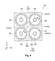
- Fig. 4 is a plan view showing an arrangement of light emitting sections and optical filter sections in the light emitting apparatus
- Fig. 5 is a schematic cross-sectional diagram showing a configuration of the light emitting section and the optical filter section in the light emitting apparatus along the A-A' line of Fig. 4 .
- the light emitting apparatus 110 of the present embodiment is provided with a plurality of scanning lines 12 and a plurality of data lines 13 that are intersected each other, and a plurality of power lines 14 that is connected in parallel with respect to the plurality of data lines 13, respectively.
- a scanning line drive circuit 16 in which the plurality of scanning lines 12 is connected, and a data line drive circuit 15 in which the plurality of data lines 13 is connected are provided.
- light emitting pixels 18 that are arranged in a matrix shape with respect to each intersection between the plurality of scanning lines 12 and the plurality of data lines 13 are provided.
- the light emitting pixels 18 are provided with the light emitting section 30 and a pixel circuit 20 that controls to drive the light emitting section 30.
- the light emitting section 30 is provided with a positive electrode 31 as the first electrode, a negative electrode 33 as the second electrode, and a functional layer 32 provided between the positive electrode 31 and the negative electrode 33.
- the functional layer 32 includes a light emitting layer made of an organic semiconductor material, and such light emitting section 30 is called as an organic EL element.
- the light emitting section 30 can be indicated as an electrical diode. It will be described in detail later, but the negative electrode 33 is formed as a common negative electrode for the plurality of light emitting pixels 18.
- the pixel circuit 20 incudes a switching transistor 21, a storage capacitor 22, and a driving transistor 23.
- the two of the transistors 21, 23 can be configured by using, for example, an n-channel type or a p-channel type thin film transistor (TFT: Think Film Transistor) or a MOS transistor.
- TFT Think Film Transistor
- a gate of the switching transistor 21 is connected to the scanning line 12, and one of the source and the drain is connected to the data line 13, and the other one of the source and the drain is connected to the gate of the driving transistor 23.
- One of the source and the drain of the driving transistor 23 is connected to the positive electrode 31 of the light emitting section 30, and the other one of the source and the drain is connected to the power line 14.
- a storage capacitor 22 is connected between the gate of the driving transistor 23 and the power line 14.
- the switching transistor 21 When the switching transistor 21 is turned on by driving the scanning line 12, an electric potential based on a control signal supplied from the data line 13 is retained in the storage capacitor 22 through the switching transistor 21.
- a state of turning on or off of the driving transistor 23 is determined in response to the gate potential of the driving transistor 23, that is, the electric potential of the storage capacitor 22.
- the driving transistor 23 When the driving transistor 23 is turned on, the electric current with the amount in response to the gate potential flows to the functional layer 32, which is sandwiched between the positive electrode 31 and the negative electrode 33, from the power line 14 via the driving transistor 23.
- the light emitting section 30 irradiates in response to the amount of the electric current that flows in the functional layer 32.
- the optical filter sections 50 are a circular shape in a plan view in order to efficiently obtain the reflected light RL from the finger F, and are arranged in an equal interval in the X-direction and the Y-direction. In other words, the optical filter sections 50 are arranged in a matrix shape with an interval in between within the planar surface defined by the X-direction and the Y-direction.
- An outline of the optical filter section 50 is slightly smaller than the outline of the microlens 122 when viewed from the Z-direction, and the microlens 122 is arranged to overlap the optical filter section 50.
- the light receiving section 142 having a circular-shaped light receiving surface, which is the same shape, is arranged.
- a light shielding film 133 pinhole substrate 130 is arranged so as to position an opening section 132 that surrounds the light receiving section 142.
- a diameter of the light receiving section 142 is, for example, 15 ⁇ m to 20 ⁇ m
- the diameter of the optical filter section 50 is, for example, 70 ⁇ m
- an arrangement interval (arrangement pitch) of the optical filter sections 50 in the X-direction and the Y-direction is, for example, 98 ⁇ m.
- the positive electrode 31 of the light emitting section 30 is arranged between the optical filter sections 50 that are arranged in a matrix shape.
- the outline of the positive electrode 31 is configured to include a portion of a circular arc, and it is a substantially cross shape.
- the positive electrodes 31 are also arranged in a matrix shape in the X-direction and the Y-direction.
- the functional layer 32 and the negative electrode 33 of the light emitting section 30 are formed in the entire region (the first region in the present invention) where the plurality of light emitting sections 30 and the plurality of optical filter sections 50 are arranged.
- a shape, a size, and an arrangement of the light emitting section 30 and the optical filter section 50 are not limited to this.
- a translucent alkali-free glass substrate, quartz substrate, etc. is used as the substrate 111.
- a base insulating film 111c that covers the first surface 111a of the substrate 111 is formed.
- a semiconductor layer 23a that configures the driving transistor 23 of the pixel circuit 20 is formed on the base insulating film 111c. It is not shown in the drawing, but the semiconductor layer 23a is not only formed on the base insulating film 111c, but also, a semiconductor layer of the switching transistor 21.
- the semiconductor layer 23a can be formed by using, for example, amorphous silicon or polysilicon.
- the gate insulating film 111d that covers the semiconductor layer 23a is formed.
- a gate electrode 23g that is opposite to the channel region of the semiconductor layer 23a is formed through the gate insulating film 111d.
- a first interlayer insulating film 111e that covers the gate electrode 23g is formed.
- contact holes CNT1, CNT2 are both coated, and a conducting film that covers the first interlayer insulating film 111 e is formed, and the power line 14 that is electrically connected to the first source drain region 23s through the contact hole CNT1 is formed by patterning the conducting film. Further, the first relay electrode 24 that is electrically connected to the second source drain region 23d through the contact hole CNT2 is formed.
- a second interlayer insulating film 111f that covers the power line 14 and the first relay electrode 24 is formed.
- the contact hole CNT3 is coated, and a conducting film that covers the second interlayer insulating film 111 f is formed, and the second relay electrode 25 is formed by patterning the conducting film.
- a third interlayer insulating film 111g that covers the second relay electrode 25 is formed.
- the reflection layer 26 is formed in an island shape (electrically independent) in a portion that is opposite to the second relay electrode 25 through the third interlayer insulating film 111g.
- a reflection layer 26 is formed by using, for example, alloy of Al (aluminum) and Nd (neodymium) having light reflectivity.
- a dielectric multilayer film 27 that covers the reflection layer 26 and an insulating film 28 are formed.
- the dielectric multilayer film 27 and the insulating film 28 will be described in detail later.
- a contact hole CNT4 that passes through the dielectric multilayer film 27 and the insulating film 28 and reaches to the second relay electrode 25 is formed.
- the contact hole CNT4 is coated, and a transparent conducting film that covers the insulating film 28 is formed, and a positive electrode 31, which is electrically connected to the second relay electrode 25 through the contact hole CNT4, and a transparent layer 51 are formed by patterning the transparent conducting film.
- the transparent layer 51 is manufactured or processed in different film thickness from the positive electrode 31. In the present embodiment, the transparent layer 51 is etched to be thinner than the film thickness of the positive electrode 31.
- a photosensitive resin layer that covers the positive electrode 31 and the transparent layer 51 is formed, and a partition wall 35 that respectively divides and surrounds the positive electrode 31 and the transparent layer 51 by exposing and developing the photosensitive resin layer.
- the partition wall 35 is formed and overlapped on the respective outer edges of the positive electrode 31 and the transparent layer 51.
- An opening is formed on the positive electrode 31 and the transparent layer 51 by the partition wall 35.
- the functional layer 32 which covers the opening and the partition wall 35 on the positive electrode 31 and the transparent layer 51, is formed.
- the functional layer 32 includes a light emitting layer that is capable of emitting the near-infrared light IL.
- a negative electrode 33 that covers the functional layer 32 is formed.
- a sealing layer 34 that covers the negative electrode 33 is formed.
- the functional layer 32, the negative electrode 33, the sealing layer 34 are formed on the entire surface of the substrate 111 by using a film formation method such as, for example, a vacuum vapor deposition, etc.
- the sealing layer 34 is provided to prevent the functional layer 32 from deteriorating or deactivating the light emitting function by entering moisture or oxygen from an external section to the functional layer 32 through the negative electrode 33.
- As a material of the sealing layer 34 an inorganic material having both properties of transparency and gas barrier such as, for example, silicon oxynitride, etc. is selected.
- the negative electrode 33 is formed as a semi-transmissive reflectivity common electrode having light permeability and light reflectivity.
- the light emission from the functional layer 32 is not only emitted from the negative electrode 33 side but also emitting from the negative electrode 33 side by transmitting the light through the positive electrode 31, which has translucency, and reflecting the light on the surface of the reflection layer 26 provided in the lower layer. Therefore, the region where the positive electrode 31 and the functional layer 32 are contacted becomes an individual light emission region in the light emitting section 30 (light emitting pixel 18).
- the partition wall 35 obtains a desired brightness of the light emission from the functional layer 32, and in other words, in order to not interrupt the light emission from the functional layer 32 or the light emission reflected in the reflection layer 26, the aforementioned photosensitive resin layer is formed by exposing and developing to form an angle between the side wall 35a, which forms the aforementioned opening, and the positive electrode 31 in a range of 30 to 60 degrees. Therefore, the cross-sectional shape of the partition wall 35 is a trapezoidal shape.
- Fig. 6 is a pattern cross-sectional diagram showing a configuration of the light emitting section and the optical filter section.
- the light emitting section 30 includes the reflection layer 26, the dielectric multilayer film 27, the insulating film 28, the positive electrode 31, the functional layer 32, and the negative electrode 33 that are laminated and formed in this order on the substrate 111.
- the negative electrode 33 is the lamination of the first layer 33a, which is made of alloy of Ag and Mg, and the second layer 33b, which is made of Mg.
- the first layer 33a is formed by using alloy including Ag, and both of the light permeability and the light reflectivity are functioned by controlling the film thickness of the first layer 33a.
- the second layer 33b is a single layer of Mg because the first layer 33a made of the alloy including Ag is easily subjected to deterioration under the influence of moisture or oxygen so that the second layer 33b functions as a protection layer of the first layer 33a.
- the second layer 33b is not limited to a single layer of Mg, and MgO (magnesium oxide) may be used. Further, a translucent resin layer that moisture or oxygen is hardly permeable may be used.
- the negative electrode 33 has the semi-transmissive reflectivity so that the light emission from the functional layer 32 is repeatedly reflected between the reflection layer 26 and the negative electrode 33, and after that, it is transmitted and emitted through the negative electrode 33. Therefore, in the light emitting section 30, the resonance occurs in response to an optical distance (length) Le between the reflection layer 26 and the negative electrode 33. That is, the light intensity of the specific resonance wavelength within the light emitting wavelength range of the functional layer 32 is enhanced and emitted.
- the configuration of such light emitting section 30 is called as the first optical resonance structure.
- the aforementioned optical distance (length) Le in the first optical resonance structure is called as a resonance length Le.
- the reflection layer 26 is not indispensable member in the first optical resonance structure, but even though the light intensity of the specific resonance wavelength becomes smaller in comparison with the case that the reflection layer 26 is provided, the optical resonance structure may be configured between the dielectric multilayer film 27 and the negative electrode 33.
- the optical filter section 50 includes the dielectric multilayer film 27, the insulating film 28, the transparent layer 51, the functional layer 32, and the negative electrode 33 that are laminated and formed in this order on the substrate 111. Since the negative electrode 33 has the semi-transmissive reflectivity, the light entered to the optical filter section 50 is repeatedly reflected between the dielectric multilayer film 27 and the negative electrode 33, and after that, it is transmitted through the dielectric multilayer film 27 and is emitted from the substrate 111 side. Therefore, the resonance occurs in response to an optical distance (length) L2 between the dielectric multilayer film 27 and the negative electrode 33 in the optical filter section 50.
- the configuration of such optical filter section 50 is called as the second optical resonance structure.
- the aforementioned optical distance (length) L2 in the second optical resonance structure is called as a resonance length L2.
- the dielectric multilayer film 27, the insulating film 28, the functional layer 32, the negative electrode 33 are shared in the light emitting section 30 and the optical filter section 50.
- the dielectric multilayer film 27 is configured by four layers in which the first dielectric film 27a and the second dielectric film 27b having different refractive indexes are alternately laminated.
- the first dielectric film 27a can be formed by, for example, silicon oxide or silicon nitride. In the present embodiment, silicon nitride is used.
- the second dielectric film 27b is formed by using a material that has larger refractive index than the first dielectric film 27a. In the present embodiment, the second dielectric film 27b is formed by using a-Si (amorphous silicon) in the present embodiment.
- the material that has larger refractive index than silicon nitride used in the first dielectric film 27a includes titanium oxide, etc., but in view of suppressing the transmission of the visible light, and in view of realizing an optical distance (length) as the dielectric multilayer film 27 in the minimum numbers of laminating layers, a-Si that has larger refractive index that titanium oxide, etc. is employed.
- the optical distance (length) L3 in each of the first dielectric film 27a and the second dielectric film 27b is set to become 1/4 of the specific wavelength ⁇ .
- An optical distance (length) L3 in the Z-direction of each layer in the dielectric multilayer film 27 is obtained by the product of the film thickness and the refractive index. Therefore, the optical distance (length) of the dielectric multilayer film 27 that is the four layers configuration is four times of L3, and that is, it is the same as the specific wavelength ⁇ .
- the insulating film 28 is provided between the dielectric multilayer film 27 and the positive electrode 31 or the transparent layer 51.
- the surface side of the positive electrode 31 of the dielectric multilayer film 27 or the transparent layer 51 becomes the second dielectric film 27b in which a-Si having conductivity is used so that the positive electrode 31 and the second dielectric film 27b are electrically insulated.
- the insulating film 28 is formed by using the silicon nitride. When the dielectric multilayer film 27 is made of an insulating material, the insulating film 28 may be omitted.
- the light entered from the first substance having the first refractive index to the second substance having the second refractive index, which is higher than the first refractive index, is reflected at a boundary surface between the first substance and the second substance. That is, in the light emitting section 30, a part of the light, which emits from the light emitting layer (EML) and transmits through the positive electrode 31 and goes toward the reflection layer 26, is reflected at the boundary surface between the insulating film 28 made of silicon nitride and the second dielectric film 27b made of a-Si. In the same manner, it is reflected at the boundary surface between the first dielectric film 27a made of silicon nitride and the second dielectric film 27b made of a-Si.
- EML light emitting layer
- the optical distance (length) L3 is set to ⁇ /4 and the phase of the light reflected at the aforementioned boundary surface is inverted so that the dielectric multilayer film 27 in the light emitting section 30 functions as a dielectric mirror in which the light of the specific wavelength ⁇ is selectively reflected.
- the light transmitting the dielectric multilayer film 27 is reflected in the reflection layer 26 so that in the reflection layer 26, the first dielectric film 27a that the refractive index is smaller than the second dielectric film 27b is laminated.
- the positive electrode 31 and the transparent layer 51 are formed by using, for example, a transparent conducting film such as ITO film, etc. As described above, the positive electrode 31 and the transparent layer 51 have different film thickness. An optical distance (length) is obtained by the product of the film thickness of the layer (substance) that the light is transmitted as described above and the refractive index.
- the film thickness of the positive electrode 31 is larger than the transparent layer 51. Therefore, an optical distance (length) between the dielectric multilayer film 27 and the negative electrode 33 in the light emitting section 30, that is, resonance length L1 is longer than a resonance length L2 between the dielectric multilayer film 27 and the negative electrode 33 in the optical filter section 50.
- the value indicated by the product of each layer of the film thickness and the refractive index is called as an optical film thickness.
- the refractive index is relied on the wavelength of the light that transmits through each layer, and as the wavelength of the light is longer, the refractive index becomes smaller.
- the functional layer 32 is configured to include the HTL (hole injection transport layer), the EML (light emitting layer), the ETL (electron transport layer), and the EIL (electron injection layer) that are laminated in this order from the positive electrode 31 side.
- the light emitting section 30 in the present embodiment is to emit the near-infrared light IL as described above.
- the configuration of the functional layer 32 that emits the near-infrared light IL the well-known configuration can be applied.
- the following material constitution of each layer is employed considering the luminance efficiency and the light emission lifetime.
- the HTL hole injection transport layer has a function to transport a hole received from the positive electrode 31 to the light emitting layer (EML). Therefore, it is preferable that the hole injection transport material included in the HTL (hole injection transport layer) has the injectability and the transportability of the holes, and an aromatic amine compound as shown in the following chemical formula (1), in which a part of the skeleton A is selected from phenylenediamine series, benzidine series, and terphenylenediamine series, is preferably used.
- An average thickness of such HTL is not specifically limited, but it is preferably approximately 5nm to 200nm, and more preferably, it is approximately 10nm to 100nm.
- the HTL hole injection transport layer
- the HTL is only provided between the positive electrode 31 and the light emitting layer.
- it may be a plurality of layers including a hole injection layer that easily injects hole from the positive electrode 31 and a hole transportation layer that easily transports hole to the light emitting layer. Further, it may include a layer that has a function to block electrons leaking from the light emitting layer to the positive electrode 31 side.
- the EML light emitting layer
- the EML is configured to include compounds (hereinafter simply referred to as "thiadiazole-based compounds or selenadiazole-based compounds”) that the basic skeleton is represented in the following chemical formula (5).
- X represents S or Se
- Y represents a functional group
- a ring may be formed.
- thiadiazole-based compounds in the following chemical formulas EML1 to EML8.
- R 1 is preferably aromatic compound (it may have substituent or may not have substituent). Specifically, aryl group, aryl group having substituent, arylamino group, and thiophenyl group are preferable. As the aryl group, phenyl group, and naphthyl group are preferable. As the aryl group having substituent, triphenyl amino group is preferable.
- R 2 is preferably hydrogen, alkyl group, alkoxy group, ester group, or aromatic compound (it may have substituent or may not have substituent). Specifically, aryl group, aryl group having substituent, arylamino group, and thiophenyl group are preferable. As the aryl group, phenyl group, and naphthyl group are preferable.
- the EML (light emitting layer) including such compounds can obtain the light emission in the wavelength region (near-infrared region) of 700nm to 1500nm.
- the EML may include luminescent materials (various types of fluorescent materials, various types of phosphorescent materials) other than the aforementioned luminescent material.
- a host material is used so that the luminescent material is added (supported) as a guest material (dopant).
- the host material is recombined with the holes and the electrons and generates excitons, and the energy of the excitons are transferred to the luminescent material (Forscter transfer or Dexter transfer), and it has a function to excite the luminescent material. Therefore, the luminance efficiency of the light emitting section 30 can be enhanced.
- the luminescent material which is the guest material is used by doping as a dopant.
- the host material quinoinolato metal complex or acene-based organic compound is preferably used.
- An anthracene-based material or a tetracene-based material is preferable, and the tetracene-based material is more preferable.
- the host material of the EML includes the acene-based material, the electrons can be efficiently delivered from the electron transport material of the ETL (electron transport layer) to the acene-based material in the EML (light emitting layer).
- an acene-based material has excellent resistance for the electrons or the holes. Also, the acene-based material has excellent thermostability. Therefore, the long life of the light emitting section 30 can be provided. Further, the acene-based material has excellent thermostability so that when the EML (light emitting layer) is formed by using a vapor phase film deposition method, it prevents the host material from degradation by the heat when the film is forming. Therefore, the EML (light emitting layer) having excellent membranous can be formed, and as the results, in this point, also, the luminance efficiency of the light emitting section 30 can be enhanced and the long life can be provided.
- the acene-based material is hart to emit itself so that it can prevent an emission spectrum of the light emitting section 30 from affecting negative influence from the host material.
- the tetracene-based material has at least one tetracene skeleton in one molecule, and also, it is not specifically limited if the material demonstrates a function as the aforementioned host material.
- the following compound represented in chemical formula IRH-1 is preferable
- the following compound represented in chemical formula IRH-2 is more preferable
- the following compound represented in chemical formula IRH-3 is further preferable. Therefore, the voltage rise at the time of continuous drive can be suppressed, and in addition, the luminance efficiency of the light emitting section 30 is enhanced, and the long life of the light emitting section 30 can be provided.
- n represents natural numbers 1 to 12
- R represents a substituent or a functional group, indicating aryl group, arylamino group that may individually include hydrogen atom, alkyl group, and substituent.
- R 1 to R 4 indicate aryl group, arylamino group that may individually include hydrogen atom, alkyl group, and substituent. Further, R 1 to R 4 may be the same each other or may be different each other.
- the tetracene-based material used as the host material is preferably configured by carbon atom and hydrogen atom. Because of this, it can prevent the host material and the luminescent material from occurring unexpected interactions. Therefore, the luminance efficiency of the light emitting section 30 can be enhanced. Further, the resistance of the host material for the electrons or holes can be enhanced. Therefore, the voltage rise at the time of continuous drive can be suppressed, and also, the long life of the light emitting section 30 can be provided.
- the compounds represented in the following chemical formulas H-1 to H-27 are preferably used.
- the content (doping amount) of the luminescent material in the EML (light emitting layer) that includes such luminescent material and host material is preferably 0.01 wt% to 10wt%, and it is more preferably 0.1 wt% to 5wt%. By setting the content of the luminescent material in this range, the luminance efficiency can be optimized.
- an average thickness of the EML is not specifically limited, but it is preferably approximately 1nm to 60nm, and more preferably, it is approximately 3nm to 50nm.
- Electron transport layer
- the ETL electrotransport layer
- the ETL has a function that transports the electrons, which are injected from the negative electrode 33 through the EIL (electron injection layer), to the EML (light emitting layer).
- ETL electrotron transport material
- ETL electrotransport layer
- phenanthroline derivative such as 2,9-dimethyl-4,7-diphenyl-1,10-phenanthroline (BCP), etc.
- 8-quinolinol such as tris(8-quinolinolato)aluminum (Alq3), etc. or quinolone derivative such as organic metal complex, etc.
- the ETL electron transport layer
- it may be configured in a mixed material that mixes more than two electron transport materials or it may be configured by laminating a plurality of layers that configuring different electron transport materials.
- the ETL electron transport layer
- the ETL includes azaindolizine derivative. More preferably, it includes azaindolizine derivative having anthracenen skeleton in molecule. The electrons can be efficiently delivered to the host material from the anthracenen skeleton in the azaindolizine derivative molecule.
- azaindolizine derivative includes the compounds represented in the following chemical formulas ETL-A1 to A24, ETL-B1 to B12, and ETL-C1 to C20.
- the average thickness of the ETL is not specifically limited, but it is preferably approximately 1nm to 200nm, and more preferably, it is approximately 10nm to 100nm.
- the layer provided between the EML (light emitting layer) and the EIL (electron injection layer) is not limited to the ETL (electron transport layer).
- ETL electron transport layer
- a plurality of layers such as a layer that the electrons are easily injected from the EIL (electron injection layer), a layer that the electrons are easily transported to the light emitting layer, or a layer that controls the amount of the electrons, which are injected to the EML (light emitting layer) may be included.
- a layer that has a function to block the leaking of the holes from the EML (light emitting layer) to the EIL (electron injection layer) may be included.
- the EIL electron injection layer
- the EIL has a function that improves the electron injection efficiency from the negative electrode 33.
- the constituent material (electron injectability material) of such EIL includes various types of inorganic insulating materials, and various types of inorganic semiconductor materials.
- inorganic insulating materials for example, it includes alkali metal chalcogenide (oxide, sulfide, selenide, telluride), alkaline earth metal chalcogenide, a halide of alkali metal, a halide of alkali earth metal, etc., and one or more materials may be used together.
- alkali metal chalcogenide oxide, sulfide, selenide, telluride
- alkaline earth metal chalcogenide a halide of alkali metal, a halide of alkali earth metal, etc.
- EIL electron injection layer
- alkali metal compound alkali metal chalcogenide, a halide of alkali metal, etc.
- EIL electron injection layer
- alkali metal chalcogenide for example, it includes Li 2 O, LiO, Na 2 S, Na 2 Se, NaO, etc.
- alkaline earth metal chalcogenide for example, it includes CaO, BaO, SrO, BeO, BaS, MgO, CaSe, etc.
- a halide of alkali metal for example, it includes CsF, LiF, NaF, KF, LiCl, KCl, NaCl, etc.
- a halide of alkali earth metal for example, it includes CaF 2 , BaF 2 , SrF 2 , MgF 2 , BeF 2 , etc.
- the inorganic semiconductor materials for example, it includes oxide, nitride, oxynitride, etc. including at least one element of Li, Na, Ba, Ca, Sr, Yb, Al, Ga, In, Cd, Mg, Si, Ta, Sb and Zn, and one or more materials may be used together.
- An average thickness of the EIL is not specifically limited, but it is preferably approximately 0.1nm to 1000nm, and more preferably, it is approximately 0.2nm to 100nm, and further more preferably, it is approximately 0.2nm to 50nm.
- the EIL electro injection layer
- the ETL electrotransport layer
- Fig. 7A is a schematic diagram showing an emission angle of light emission with respect to a light axis of the light emitting section
- Fig. 7B is a schematic diagram showing an integrating sphere that describes an intensity of the light of the light emitting section
- Fig. 8 is a graph showing a relationship between an emission angle of the light emission and a peak wavelength of the light intensity
- Fig. 9 is a graph showing a relationship between an emission wavelength from the light emission section and an omnidirectional integral value of the light intensity.
- Fig. 8 shows the observation of the light intensity when the emission angle ⁇ with respect to the light axis L0 is 0° to 80°, and a relative intensity is converted into a numerical value on the basis of the light intensity when the vertical axis is 0°.
- the light axis L0 of the light emitting section 30 arranged on the surface defined by the X-direction and the Y-direction is defined along the Z-direction that intersects the X-direction and the Y-direction.
- the light emission region in each light emitting section 30 is the region where the positive electrode 31 divided by the partition wall 35 and the functional layer 32 are contacted, and however, here, it defines that the light emitting section 30 is approximately the point light source.
- the emission angle ⁇ is 0°, that is, the peak wavelength in the intensity of the light emitted in the direction along the light axis L0 is the largest, and as the angle is larger than the emission angle 0°, the peak wavelength in the light intensity becomes smaller. This indicates that by relying on the emission angle ⁇ of the light in the light emitting section 30, as the emission angle ⁇ is larger, the resonance length Le becomes smaller (shorter).
- the emission angle ⁇ of the light emitted from the light emitting section 30 is actually limited in an angular range of the partition wall 35, which is formed in a trapezoid shape when viewed in the cross-section, but the intensity of the light emitted in the angular range includes the light in the peak wavelength in response to the emission angle ⁇ .
- the light intensity from which the emission angle ⁇ as shown in Fig. 8 is 0° to 80° is integrated, it becomes the graph of the spectral characteristics shown in Fig. 9 .
- the intensity of the light emitted from the light emitting section 30 becomes the emission characteristics that are close to the spectral characteristics in the photoluminescence (PL) of the luminescent material in the EML (light emitting layer).
- the light receiving and emitting apparatus 150 is to take a vein image (vein pattern) by irradiating the near-infrared light IL from the light emitting section 30 to the finger F as a living body.
- a method of which the light that the near-infrared light IL was emitted in the emission angle ⁇ with respect to the light axis L0 and was reflected at the finger F is selectively received in the light receiving section 142 reduces the influence of the light, which was reflected at the finger F, than a method of which the light that the near-infrared light IL was emitted in the direction of the light axis L0, that is, the Z-direction from the light emitting section 30 and was reflected at the finger F is received in the light receiving section 142 so that the light reached to and reflected at the inside of the finger F can be received in the light receiving section 142.
- the configuration of each layer of the light emitting section 30 and the optical filter section 50 is set in a condition that the Z-direction of the light emitting apparatus 110, that is, the peak wavelength ⁇ 1 of the front surface is set as, for example, 805nm, and the peak wavelength ⁇ 2 when the emission angle ⁇ is 40 degree that the actual intensity of the light emission from the light emitting section 30 becomes the largest, is set as, for example, 770nm.
- the light emitting apparatus 110 is applied to the light receiving and emitting apparatus 150 of the biometric authentication apparatus 100 so that in order to obtain a vivid vein image (vein pattern), the target peak wavelength ⁇ 2 in the light emitting section 30 and the optical filter section 50 is 770nm.
- Fig. 10A is a table showing an optical film thickness in each layer of the light emitting section and the optical filter section in Example 1; and Fig. 10B is a table showing an optical film thickness in each layer of the light emitting section and the optical filter section in Example 2.
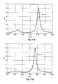
- Fig. 11A is a graph showing spectral characteristics of a transmittance in the optical filter section in Example 1; and Fig. 11B is a graph showing spectral characteristics of a transmittance in the optical filter section in Example 2.
- the configuration of the light emitting section 30 in Example 1 is that in the order from the lower side, the film thickness of the reflection layer 26 made of Al and Nd is 80nm; the film thickness of the first dielectric film 27a made of silicon nitride is 104nm; the film thickness of the second dielectric film 27b made of a-Si is 48nm; the film thickness of the insulating film 28 made of silicon nitride is 50nm; the film thickness of the positive electrode 31 is 63nm; the film thickness of the HTL (hole injection transport layer) is 30nm; the film thickness of the EML (light emitting layer) is 25nm; the film thickness of the ETL (electron transport layer) is 60nm; the film thickness of the EIL (electron injection layer) made of LiF is 1nm; the film thickness of the first layer 33a (MgAg alloy layer in which volume ratio is 1:20) of the negative electrode 33 is 20nm; and the film thickness of the
- the HTL hole injection transport layer
- HTL12 uses benzidine series and aromatic amine compound indicated in the aforementioned chemical formula HTL12 as a hole injection transport material.
- the EML (light emitting layer) uses thiadiazole-based compound indicated in the aforementioned chemical formula EML5 as a luminescent material (dopant), and tetracene-based compound indicated in the aforementioned chemical formula H-5 is used.
- the ETL (electron transport layer) uses azaindolizine derivative indicated in the aforementioned chemical formula ETL-A3.
- the functional layer 32 is configured by forming each of the HTL (hole injection transport layer), the EML (light emitting layer), the ETL (electron transport layer), and the EIL (electron injection layer) over the region (the first region) where the plurality of light emitting sections 30 and the plurality of optical filter sections 50 are arranged so that the light emitting sections 30 and the optical filter sections 50 are commonly formed.
- the film thickness of the transparent layer 51 is 52nm.
- the positive electrode 31 and the transparent layer 51 are formed by patterning the ITO film that was filmed in the same layer on the substrate 111. Further, a portion corresponding to the transparent layer 51 within the patterned ITO film is selectively etched to provide a reduction film so that the film thickness of the transparent layer 51 is smaller than the positive electrode 31.
- the optical film thickness of the first dielectric film 27a is 192.4nm
- the optical film thickness of the second dielectric film 27b is 193.9nm. Therefore, the respective optical film thicknesses of the first dielectric film 27a and the second dielectric film 27b is approximately 1/4 of the value (770nm) that was set as the peak wavelength ⁇ 2 when the emission angle ⁇ of the light emitting section 30 is 40 degree.
- the specific wavelength ⁇ that enhances the light intensity than the dielectric multilayer film 27 of Example 1 is approximately 770nm.
- the optical film thickness of the insulating film 28 is 92.5nm; the optical film thickness of the positive electrode 31 is 106.5nm; the optical film thickness of the transparent layer 51 is 87.9nm; the optical film thickness of the HTL (hole injection transport layer) is 51.6nm; the optical film thickness of the EML (light emitting layer) is 43nm; the optical film thickness of the ETL (electron transport layer) is 108nm; and the optical film thickness of the EIL (electron injection layer) is 1.4nm.
- the resonance length L1 between the dielectric multilayer film 27 and the negative electrode 33 in the light emitting section 30 of Example 1 is 403nm which is the total optical film thicknesses of the respective layers.
- the resonance length L1 is approximately half of the value (805nm) that was set as the peak wavelength ⁇ 1 of the front surface of the light emitting section 30. That is, the resonance length L1 is approximately ⁇ 1 /2.
- the resonance length L2 between the dielectric multilayer film 27 and the negative electrode 33 in the optical filter section 50 of Example 1 is 384.4nm that is the total of the optical film thicknesses of the respective layers.
- the peak wavelength of the front surface in the optical filter section 50 that is, the setting of the wavelength that indicates the highest transmittance within the light transmitting the optical filter section 50 assumes the light that has the peak wavelength ⁇ 2 when the emission angle ⁇ in the light emitting section 30 is 40 degree.
- the optical filter section 50 is configured to selectively transmit the light in the wavelength range including the peak wavelength ⁇ 2 .
- the resonance length L2 of the optical filter section 50 of Example 1 is approximately ⁇ 2 /2.
- the spectral characteristics of the light transmitted through the optical filter section 50 of Example 1 generate a peak that the transmittance in the wavelength of 805nm exceeds 60%, and more than or equal to 20% of the near-infrared light in the wavelength range of 780nm to 840nm was transmitted.
- the transmittance of the near-infrared light in the near-infrared wavelength range other than the wavelength range of 780nm to 840nm is less than 20%.
- the transmittance in vicinity of 530nm in the visible light wavelength region generates a peak of approximately 8%, and more than or equal to 5% of the visible light in the wavelength range of 480nm to 560nm was transmitted.
- the transmittance of the visible light other than the wavelength range of 480nm to 560nm is less than 5%.
- Example 1 even though the optical filter section 50 does not sufficiently transmit the near-infrared light of the peak wavelength ⁇ 2 (770nm) that the emission angle ⁇ is 40 degree and the intensity of the light emission from the light emitting section 30 is strong, however, the light in the wavelength of the vicinity of 800nm which is larger than 770nm is sufficiently transmitted. Therefore, the light receiving and emitting apparatus 150 in which the light emitting apparatus 110 of Example 1 is applied replaces the light of the vicinity of 800nm within the reflected light RL from the finger F to an electrical signal by the light receiving section 142, and also, the influence of the visible light is suppressed so that a vivid vein image (vein pattern) can be taken.
- the light receiving and emitting apparatus 150 in which the light emitting apparatus 110 of Example 1 is applied replaces the light of the vicinity of 800nm within the reflected light RL from the finger F to an electrical signal by the light receiving section 142, and also, the influence of the visible light is suppressed so that a vivid vein image (vein pattern) can
- the configuration of the light emitting section 30 of Example 2 is that in the order from the lower layer side, the film thickness of the reflection layer 26 made of Al and Nd is 80nm; the film thickness of the first dielectric film 27a made of silicon nitride is 104nm, the film thickness of the second dielectric film 27b made of a-Si is 48nm; the film thickness of the insulating film 28 made of silicon nitride is 50nm; the film thickness of the positive electrode 31 is 48nm; the film thickness of the HTL (hole injection transport layer) is 30nm; the film thickness of the EML (light emitting layer) is 25nm; the film thickness of the ETL (electron transport layer) is 60nm; the film thickness of the EIL (electron injection layer) made of LiF is 1nm; the film thickness of the first layer 33a (MgAg alloy layer in which volume ratio is 1:20) of the negative electrode 33 is 20nm; and the film thickness of the
- the optical filter section 50 of Example 2 shares the light emitting section 30, the dielectric multilayer film 27, and the functional layer 32, only the film thickness of the transparent layer 51 is different from the light emitting section 30.
- the film thickness of the transparent layer 51 is 32nm.
- Example 2 makes smaller (thinner) the film thickness of the positive electrode 31 and the transparent layer 51, and the configuration of the respective layers and the formation method are the same as Example 1.
- the optical film thickness of the first dielectric film 27a is 192.4nm
- the optical film thickness of the second dielectric film 27b is 193.9nm. Therefore, as described above, it is approximately 1/4 of the value (770nm) that was set as the peak wavelength ⁇ 2 .
- the optical film thickness of the insulating film 28 is 92.5nm; the optical film thickness of the positive electrode 31 is 81.1nm; the optical film thickness of the transparent layer 51 is 54.1nm; the optical film thickness of the HTL (hole injection transport layer) is 51.6nm; the optical film thickness of the EML (light emitting layer) is 43nm; the optical film thickness of the ETL (electron transport layer) is 108nm; and the optical film thickness of the EIL (electron injection layer) is 1.4nm.
- the resonance length L1 between the dielectric multilayer film 27 and the negative electrode 33 in the light emitting section 30 of Example 2 is 377.6nm which is the total optical film thicknesses of the respective layers.
- the resonance length L1 is smaller than 1/2 of the value (805nm) that was set as the peak wavelength ⁇ 1 of the front surface of the light emitting section 30.
- the graph showing the spectral characteristics corresponding to the emission angle ⁇ as shown in Fig. 8 and the graph showing the spectral characteristics due to an omnidirectional integral as shown in Fig. 9 indicate the spectral characteristics of the light emitting section 30 of Example 2. That is, the peak wavelength of the actual light intensity of the light emission from the light emitting section 30 is 770nm.
- the resonance length L2 between the dielectric multilayer film 27 and the negative electrode 33 in the optical filter section 50 of Example 2 is 350.6nm that is the total of the optical film thicknesses of the respective layers.
- the peak wavelength of the front surface in the optical filter section 50 that is, as described above, the wavelength that indicates the highest transmittance within the light transmitting the optical filter section 50 assumes the light that has the peak wavelength ⁇ 2 when the emission angle ⁇ in the light emitting section 30 is 40 degree.
- the optical filter section 50 is configured to selectively transmit the light in the wavelength range including the peak wavelength ⁇ 2 .
- the resonance length L2 of the optical filter section 50 of Example 2 is smaller than the value of ⁇ 2 /2.
- the spectral characteristics of the light transmitted through the optical filter section 50 of Example 2 generate a peak that the transmittance in the wavelength of 770nm reaches 60%, and more than or equal to 20% of the near-infrared light in the wavelength range of 740nm to 800nm was transmitted. Further, the transmittance in vicinity of 530nm in the visible light wavelength region generates a peak of approximately 5%, and the transmittance of the visible light other than the wavelength range of 480nm to 560nm is less than 3%.
- Example 2 the specific wavelength ⁇ in Example 2 that transmits the optical filter section 50 almost corresponds to the target peak wavelength ⁇ 2 than Example 1.
- the transmittance in the visible light wavelength region is reduced. That is, the light receiving and emitting apparatus 150 applied to the light emitting apparatus 110 of Example 2 is possible to take more vivid vein image (vein pattern) that has less noise in comparison with Example 1.
- the resonance length L1 of the light emitting section 30 is ⁇ 1 /2
- the resonance length L2 of the optical filter section 50 is ⁇ 2 /2 as described in Example 1
- the peak wavelength in the spectral characteristics of the light that transmits through the optical filter section 50 slightly shifts to the long-wavelength side in Example 2 because it is considered the reason that the first optical resonance structure and the second optical resonance structure are respectively functioned as a dielectric mirror, and the dielectric multiplayer film 27, the functional layer 32, and the negative electrode 33 are shared.
- the negative electrode has the semi-transmissive reflectivity and a property to absorb the light. Therefore, in Example 1 and Example 2, the film thickness of the first layer 33a made of MgAg is set to 20nm to efficiently transmit the light in the wavelength of 770nm set as the peak wavelength ⁇ 2 .
- the second layer 33b made of Mg that functions as the protection layer of the first 33a has smaller film thickness than the first layer 33a so that it is less effect to the transmittance of the light in the negative electrode 33. Further, when the light emitted from the light emitting layer is reflected on the surface in the functional layer 32 side of the negative electrode 33, it is known to shift a phase of the light emission.
- Example 2 the optical film thickness (15nm to 20nm) corresponding to approximately half of the amount (35nm) that the peak wavelength of the transmittance in the optical filter section 50 of Example 1 is shifted to the long-wavelength side than the target wavelength is reduced from the optical film thickness which is the simple target of the positive electrode 31 and the transparent layer 51.
- Such adjustment of the optical film thickness can realize the desired spectral characteristics of the light emitting section 30 and the desired permeability characteristics of the optical filter section 50 by repeating optical simulations and providing experimental productions of the light emitting apparatus 110.
- Fig. 12 is a schematic plan view showing an arrangement of the light emitting sections and the optical filter sections in the light emitting apparatus of the second embodiment
- Fig. 13A is a schematic cross-sectional diagram showing a configuration of the first light emitting section and the first optical filter section
- Fig. 13B is a schematic cross-sectional diagram showing a configuration of the third light emitting section and the third optical filter section.
- Fig. 14A is a table showing a detailed configuration of the light emitting section and the optical filter section in the second light emitting apparatus
- Fig. 14B is a table showing a wavelength dependency of a refractive index in each layer configuring the light emitting section and the optical filter section.
- the light emitting apparatus of the second embodiment has a difference in a point that a plurality of light emitting sections, which has different value of the target peak wavelength ⁇ 1 of the front surface in the light emission, and a plurality of optical filter sections, which has different value of the target peak wavelength ⁇ 2 in the optical transmittance.
- the same symbols are used in the same structures of the first embodiment so that the detailed descriptions are omitted.
- the light emitting apparatus 210 of the present embodiment is provided with the first light emitting sections 30A, the second light emitting sections 30B, the third light emitting sections 30C, the first optical filter sections 50A, the second optical filter sections 50B, and the third optical filter sections 50C.
- the light emitting wavelength ranges of the first light emitting sections 30A, the second light emitting sections 30B, and the third light emitting sections 30C are shifted each other so that it has a configuration to obtain the light emission of the different peak wavelength ⁇ 1 in the front surface side. Further, the size of the peak wavelength ⁇ 1 is in the order of the first light emitting sections 30A ⁇ the second light emitting sections 30B ⁇ the third light emitting sections 30C.
- the wavelength ranges of the transmitted light of the first optical filter sections 50A, the second optical filter sections 50B, and the third optical filter sections 50C are shifted each other so that the size of the peak wavelength ⁇ 2 in the transmittance of the transmitted light is in the order of the first optical filter sections 50A ⁇ the second optical filter sections 50B ⁇ the third optical filter sections 50C.
- the third optical filter sections 50C are arranged to surround the second optical filter section 50B in the X-direction and the Y-direction. Further, the first optical filter sections 50A are arranged in a diagonal direction that intersects the X-direction and the Y-direction with respect to the second optical filter section 50B.
- the first light emitting section 30A, the second light emitting section 30B, and two of the third light emitting sections 30C are arranged in an adjacent position with respect to the second optical filter section 50B. Two of the third light emitting sections 30C are arranged in a diagonal direction so as to sandwich the second optical filter section 50B.
- the one pixel is configured to include nine optical filter sections 50 in which the second optical filter section 50B is located in the center, and the first light emitting sections 30A, the second light emitting sections 30B, and the third light emitting sections 30C that have different peak wavelengths ⁇ 1 in the emission luminance. Further, the light emitting sections 30 that have the different peak wavelengths ⁇ 1 , that is, the light sources for illumination are arranged in equal distance with respect to one of the optical filter sections 50.
- the light receiving section 142 arranged corresponding to the optical filter section 50 is an optical sensor using, for example, amorphous silicon
- the sensitivity of the optical sensor tends to get lowered as the incident light wavelength is larger (longer).
- two of the third light emitting sections 30C are arranged in the aforementioned one pixel so that the lowering sensitivity of the optical sensor in the long wavelength is compensated.
- the shape of the first optical filter section 50A, the second optical filter section 50B, and the third optical filter section 50C is a circular shape, and in the center of it, the light receiving section 142 is arranged. Further, a light shielding film 133 that has an opening section 132 surrounding the light receiving section 142 is arranged between the respective of the first optical filter section 50A, the second optical filter section 50B, the third optical filter section 50C and the light receiving section 142.
- a microlens 122 is arranged between the respective of the first optical filter section 50A, the second optical filter section 50B, the third optical filter section 50C and the light shielding film 133 to overlap with the respective of the first optical filter section 50A, the second optical filter section 50B, the third optical filter section 50C.
- the first optical filter section 50A has a circular-shaped transparent layer 51A with the same center.
- the second optical filter section 50B also has a circular-shaped transparent layer 51B with the same center.
- the third optical filter section 50C also has a circular-shaped transparent layer 51C with the same center.
- each of the transparent layers 51A, 51B, 51C is shown, but the film thickness of the transparent layer 51A in the first optical filter section 50A of the specific example is "0nm", that is, the transparent layer 51A is not existed.
- the first light emitting section 30A has a substantially cross-shape positive electrode 31A in plan view.
- the second light emitting section 30B has a substantially cross-shape positive electrode 31B in the plan view.
- the third light emitting section 30C has a substantially cross-shape positive electrode 31C in the plan view.
- a shape, a size, and an arrangement of the first light emitting section 30A, the second light emitting section 30B, the third light emitting section 30C, the first optical filter section 50A, the second optical filter section 50B, the third optical filter section 50C are not limited to this.
- the dielectric multilayer film 27, the functional layer 32, and the negative electrode 33 are arranged over the region where the first light emitting section 30A, the second light emitting section 30B, the third light emitting section 30C, the first optical filter section 50A, the second optical filter section 50B, and the third optical filter section 50C are arranged.
- the first light emitting section 30A has the reflection layer 26, the dielectric multilayer film 27, the insulating film 28, the positive electrode 31A, the functional layer 32, and the negative electrode 33 on the substrate 111 and they are laminated in this order.
- the first optical filter section 50A has the dielectric multilayer film 27, the insulating film 28, the transparent layer 51A, the functional layer 32, and the negative electrode 33 on the substrate 111 and they are laminated in this order.
- the third light emitting section 30C has the reflection layer 26, the dielectric multilayer film 27, the insulating film 28, the positive electrode 31C, the functional layer 32, and the negative electrode 33 on the substrate 111 and they are laminated in this order.
- the third optical filter section 50C has the dielectric multilayer film 27, the insulating film 28, the transparent layer 51C, the functional layer 32, and the negative electrode 33 on the substrate 111 and they are laminated in this order.
- the configuration of the second light emitting section 30B and the second optical filter section 50B is basically the same configuration of the light emitting section 30 and the optical filter section 50 in the first embodiment. That is, the second light emitting section 30B has the reflection layer 26, the dielectric multilayer film 27, the insulating film 28, the positive electrode 31B (corresponding to positive electrode 31), the functional layer 32, and the negative electrode 33 on the substrate 111 and they are laminated in this order.
- the second optical filter section 50B has the dielectric multilayer film 27, the insulating film 28, the transparent layer 51B (corresponding to the transparent layer 51), the functional layer 32, and the negative electrode 33 on the substrate 111 and they are laminated in this order.
- the first light emitting section 30A, the second light emitting section 30B, the third light emitting section 30C, the first optical filter section 50A, the second optical filter section 50B, and the third optical filter section 50C respectively share the dielectric multilayer film 27, the insulating film 28, the functional layer 32, and the negative electrode 33. Further, the configurations of the positive electrode and the transparent layer are respectively different.
- first light emitting section 30A The specific configuration in the first light emitting section 30A, the second light emitting section 30B, the third light emitting section 30C, the first optical filter section 50A the second optical filter section 50B, and the third optical filter section 50C will be described in Fig. 14A .
- the optical film thickness of each layer is obtained by the product of the film thickness and the refractive index as described above, but the refractive index relies on the wavelength of the light transmitting through the layer so that the refractive index with respect to the targeted wavelength of each layer is shown in Fig. 14B .
- the insulating film 28 respectively shared by the first light emitting section 30A, the second light emitting section 30B, the third light emitting section 30C, the first optical filter section 50A, the second optical filter section 50B, and the third optical filter section 50C is made of, for example, silicon nitride, and the film thickness is 50nm.
- the optical film thickness of the insulating film 28 in the first light emitting section 30A and the first optical filter section 50A that the peak wavelength ⁇ 2 when the emission angle ⁇ is 40 degree is 710nm is 93nm.
- the optical film thickness of the insulating film 28 of the second light emitting section 30B and the second optical filter section 50B, the third light emitting section 30C and the third optical filter section 50C becomes smaller, and it is 92.5nm.
- the functional layer 32 shared by the first light emitting section 30A, the second light emitting section 30B, the third light emitting section 30C, the first optical filter section 50A, the second optical filter section 50B, and the third optical filter section 50C respectively is the same as the first embodiment, and it has the HTL (hole injection transport layer), the EML (light emitting layer), the ETL (electron transport layer), and the EIL (electron injection layer). Further, the film thickness of the HTL (hole injection transport layer) is 30nm; the film thickness of the EML (light emitting layer) is 25nm, the film thickness of the ETL (electron transport layer) is 60nm; and the film thickness of the EIL (electron injection layer) is 1nm.
- the material configuration or the formation method of each layer in the functional layer 32 is the same content described in the examples of the first embodiment.
- the film thickness of the positive electrode 31A of the first emitting section 30A is 16nm.
- the film thickness of the transparent layer 51A of the first optical filter section 50A is 0nm, that is, the transparent layer 51A is not actually provided in the first optical filter section 50A.
- the film thickness of the positive electrode 31B of the second light emitting section 30B is 48nm, and the film thickness of the transparent layer 51B of the second optical filter section 50B is 32nm. That is, it is the same as Example 2 in the first embodiment.
- the film thickness of the positive electrode 31C of the third light emitting section 30C is 80nm and the film thickness of the transparent layer 51C of the third optical filter section 50C is 64nm.
- Each of the positive electrodes 31 A, 31B, 31C, and the transparent layers 51B, 51C is made of, for example, ITO film.
- the resonance length L4 between the dielectric multilayer film 27 and the negative electrode 33 in the first light emitting section 30A is 328.5nm.
- the resonance length L5 between the dielectric multilayer film 27 and the negative electrode 33 in the first optical filter section 50A is 300.5nm.
- the resonance length L1 between the dielectric multilayer film 27 and the negative electrode 33 in the second light emitting section 30B is 379.9, and the resonance length L2 between the dielectric multilayer film 27 and the negative electrode 33 in the second optical filter section 50B is 352.8nm.
- the resonance length L6 between the dielectric multilayer film 27 and the negative electrode 33 in the third light emitting section 30C is 428.7nm and the resonance length L7 between the dielectric multilayer film 27 and the negative electrode 33 in the third optical filter section 50C is 402.6nm (see Fig. 6 , Fig. 13A and Fig. 13B ).
- the dielectric multilayer film 27 shared by the first light emitting section 30A, the second light emitting section 30B, the third light emitting section 30C, the first optical filter section 50A, the second optical filter section 50B, and the third optical filter section 50C respectively is configured by four layers in which for example, the first dielectric film 27a made of silicon nitride and the second dielectric film 27b made of a-Si are alternately laminated (see Figs. 13A and 13B ).
- the film thickness of the first dielectric film 27a is 95nm
- the film thickness of the second dielectric film 27b is 47.4nm.
- the optical film thickness of the first dielectric film 27a in the first light emitting section 30A is 176.7nm, and it is approximately 1/4 of the peak wavelength ⁇ 2 .
- the optical film thickness of the second dielectric film 27b in the first light emitting section 30A is 196.7nm, and it is larger than 1/4 of the peak wavelength ⁇ 2 .
- the dielectric multilayer film 27 has a configuration that the dielectric multilayer film 27 is respectively shared by the first light emitting section 30A, the second light emitting section 30B, the third light emitting section 30C, the first optical filter section 50A, the second optical filter section 50B, and the third optical filter section 50C so that the configuration of the dielectric multilayer film 27 employs the condition of the first light emitting section 30A and the first optical filter section 50A that the target peak wavelength ⁇ 2 is the smallest. Therefore, as the value of the target peak wavelength ⁇ 2 is larger, the value of the optical film thickness of the dielectric multilayer film 27 becomes smaller in comparison with the first light emitting section 30A and the first optical filter section 50A.
- the optical sensor when the optical sensor by using, for example, the aforementioned amorphous silicon is employed as the light receiving section 142, the optical sensor maximizes the sensitivity for the light in the wavelength of 600nm within the visible light wavelength range. Therefore, the noise caused by the visible light at the time of taking an image is reduced so that it is preferable that the optical filter section avoids transmitting through the light of 600nm.
- the film thickness of each layer is preferably set on the basis of the third optical filter section 50C that the optical film thickness becomes the smallest.
- the dielectric multilayer film 27 is configured by which as an example, the film thickness of the first dielectric film 27a made of silicon nitride is set 95nm, and the film thickness of the second dielectric film 27b made of a-Si is set 47.4nm.
- the light emission of the peak wavelength ⁇ 1 of the front surface and the peak wavelength ⁇ 2 when the emission angle ⁇ is 40 degree is obtained in the light emitting section, and the light in the wavelength range including the peak wavelength ⁇ 2 is selectively transmitted in the optical filter section.
- Fig. 15A shows the spectral characteristics in the first light emitting section
- Fig. 15B shows the omnidirectional integral waveform of the light emission in the first light emitting section and the permeability characteristics of the first optical filter section
- Fig. 15C is a graph showing the spectral characteristics of the light transmitted through the first optical filter section.
- Fig. 16A shows the spectral characteristics in the second light emitting section
- Fig. 16B shows the omnidirectional integral waveform of the light emission in the second light emitting section and the permeability characteristics of the second optical filter section
- Fig. 16C is a graph showing the spectral characteristics of the light transmitted through the second optical filter section.
- Fig. 17A shows the spectral characteristics in the third light emitting section; Fig.
- Fig. 17B shows the omnidirectional integral waveform of the light emission in the third light emitting section and the permeability characteristics of the third optical filter section; and Fig. 17C is a graph showing the spectral characteristics of the light transmitted through the third optical filter section.
- the permeability characteristics of the optical filter section is the permeability characteristics of the light including the substrate 111 on which the optical filter section is provided, and the transmittance of the light in a blank condition that the optical filter section is not provided on the substrate 111 is defined as 100%.
- the light emission that the peak wavelength ⁇ i in the front surface is approximately 740nm is obtained.
- the peak wavelength ⁇ 2 when the emission angle ⁇ is 40 degree is approximately 710nm.
- the peak wavelength of the light intensity is approximately 730nm.
- the permeability characteristics of the first optical filter section 50A are obtained in a peak of the transmittance in vicinity of approximately 700nm, and as shown in Fig. 15C , the peak wavelength ⁇ 2 of the light transmitted through the first optical filter section 50A is approximately 710nm.
- the light emission that the peak wavelength ⁇ 1 in the front surface is approximately 805nm is obtained.
- the peak wavelength ⁇ 2 when the emission angle ⁇ is 40 degree is approximately 770nm.
- the peak wavelength of the light intensity is approximately 760nm.
- the permeability characteristics of the second optical filter section 50B are obtained in a peak of the transmittance in vicinity of approximately 770nm, and as shown in Fig. 16C , the peak wavelength ⁇ 2 of the light transmitted through the second optical filter section 50B is approximately 770nm.
- the light emission that the peak wavelength ⁇ 1 in the front surface is approximately 860nm is obtained.
- the peak wavelength ⁇ 2 when the emission angle ⁇ is 40 degree is approximately 820nm.
- the peak wavelength of the light intensity is approximately 790nm.
- the permeability characteristics of the third optical filter section 50C are obtained in a peak of the transmittance in vicinity of approximately 830nm, and as shown in Fig. 17C , the peak wavelength ⁇ 2 of the light transmitted through the third optical filter section 50C is approximately 830nm.
- a simple formation and configuration of the light emitting apparatus 210 provided with three types of the light emitting sections and the optical filter sections that can obtain the light emission of the peak wavelength ⁇ 2 when the emission angle ⁇ is 40 degree in the light emitting section and can selectively transmit the light in the wavelength range including the light of the peak wavelength ⁇ 2 in the optical filter section can be provided by sharing the dielectric multilayer film 27, the insulating film 28, and the functional layer 32, and differentiating the film thickness of the transparent layer 51 with respect to the film thickness of the positive electrode 31.
- Fig. 18 is a graph showing the spectral characteristics related to the absorption coefficient of oxygenated hemoglobin and deoxygenated hemoglobin in blood.
- the light in the wavelength between 700nm to 1000nm within the near-infrared wavelength region reaches to the deeper portion of the living body and can obtain the information for the inside of the living body in comparison with the light in the wavelength region (400nm to 700nm).
- Fig. 18 it is well-known that the in the near-infrared wavelength between 700nm to 1000nm, the light absorption coefficients (cm -1 mM -1 ) of oxygenated hemoglobin (oxy-Hb) and deoxygenated hemoglobin (deoxy-Hb) in the blood, that is, spectrums, are different. Further, an equivalent point of the light absorption coefficients (cm -1 mM -1 ) of oxygenated hemoglobin (oxy-Hb) and deoxygenated hemoglobin (deoxy-Hb) is existed in vicinity of 805nm.
- the light in at least two near-infrared wavelengths divided by 805nm as a boundary, or three near-infrared wavelengths if possible is emitted to the living body, and when the degree of absorption is measured, it is possible to accurately obtain the change amount of oxygenated hemoglobin (oxy-Hb) and deoxygenated hemoglobin (deoxy-Hb) in the blood. Since the hemoglobin has a role to supply oxygen in the living body, by measuring the change amount of oxygenated hemoglobin (oxy-Hb) and deoxygenated hemoglobin (deoxy-Hb) in the blood, it can obtain the oxygen supply state or the metabolic state in the living body. Also, deoxygenated hemoglobin is called as reduced hemoglobin.
- the light emitting apparatus 210 is used instead of the light emitting apparatus 110 in the light receiving and emitting apparatus 150 of the first embodiment, it is the active driving type of the light emitting apparatus 210 so that the first emitting section 30A of which the peak wavelength ⁇ 2 is 710nm when the emission angle ⁇ is 40 degree, the second emitting section 30B of which the peak wavelength ⁇ 2 is also 770nm, and the third light emitting section 30C of which the peak wavelength ⁇ 2 is 820nm are respectively selected and the light can be emitted.
- the light receiving apparatus 140 receives the near-infrared light, which was transmitted through the first optical filter section 50A of which the peak wavelength ⁇ 2 of the transmittance is 710nm, the second optical filter section 50B of which the peak wavelength ⁇ 2 of the transmittance is 770nm, and the third optical filter section 50C of which the peak wavelength ⁇ 2 of the transmittance is 830nm, in the light receiving section 142, and it can be converted to an electrical signal. That is, the change amount of oxygenated hemoglobin (oxy-Hb) and deoxygenated hemoglobin (deoxy-Hb) in the blood can be accurately obtained as the biometric information.
- oxygenated hemoglobin oxygenated hemoglobin
- deoxy-Hb deoxygenated hemoglobin
- the light emitting apparatus 210 is not limited to the configuration that is provided with the plurality of light emitting sections (three types) and the plurality of optical filter sections (three types).
- it may be a configuration that is provided with one type of the light emitting section and two types of the optical filter sections in which the wavelength ranges of the transmitted light are different.
- it may be a configuration that is provided with two types of the light emitting sections that emit the light with different wavelengths and one type of the optical filter section that transmits the light in a specific wavelength range.
- the measuring object is not only hemoglobin in the blood, but also, glucose by analyzing the absorbing spectrum of the near-infrared light so that the amount of glucose in the blood can be obtained, and the aforementioned light receiving and emitting apparatus 150 can be used as a noninvasive blood glucose level measurement apparatus.
- the intensity of the light emitted from the light emitting section 30 is preferably more than or equal to 100mW/cm 2 .
- the intensity of the light in each light emitting section 30 is preferably more than or equal to 0. 1mW/cm 2 .
- Fig. 19 shows a relationship in the arrangement between the light emitting sections and the optical filter sections in a plan view.
- a distance d1 from the center of the light emitting section 30 to the outer edge of the light emitting section 30 preferably satisfies the relationship of 5 ⁇ m ⁇ d1 ⁇ 0. 7mm.
- the light emitting section 30 can be arranged to avoid entering a circuit element or a wire, which is used for driving the light emitting section 30, in the optical filter section 50. Further, when the light emitting apparatus 110 is used for, for example, the light receiving and emitting apparatus 150, etc. that is possible to obtain various biometric information, by setting the distance from the center of the light emitting section 30 to the outer edge which is less than or equal to 0. 7mm, it is possible to obtain the biometric information as the high-resolution image information.
- a distance d2 from the center of the optical filter section 50 to the outer edge of the optical filter section 50 is preferably equal to the aforementioned distance d1 or larger than the aforementioned distance d1. Therefore, the light emitted in the outer edge of the light emitting section 30 and reflected at the subject is easily obtained in the optical filter section 50.
- the light emitted from the light emitting section 30 can be efficiently received by the light receiving section 142.
- the light-gathering capability by the microlens 122 becomes important so that the aforementioned distance d2 of the optical filter section 50 preferably satisfies the relationship of d2 ⁇ d/2.
- the authentication accuracy is important in the aforementioned biometric authentication apparatus 100 so that the pitch between the light emitting section 30 and the optical filter section 50 is finely arranged as much as possible.
- the distance d from the center of the light emitting section 30 and the center of the optical filter section 50 in the first embodiment is approximately 70 ⁇ m.
- the distance d1 from the center of the light emitting section 30 to the outer edge is approximately 25 ⁇ m.
- the distance d2 from the center of the optical filter section 50 to the outer edge is larger than the aforementioned distance d1 and is approximately 35 ⁇ m. That is, the arrangement of the light emitting sections 30 and the optical filter sections 50 in the first embodiment satisfies the aforementioned relationship.
- the measuring object to be measured by receiving the reflected light RL from the living body in a fixed distance with the living body by the light emitting section 30 as a point light source and the light receiving section 142 it includes blood components (blood glucose value, venous blood oxygen concentration, cholesterol value, hemoglobin amount, water amount, etc.).
- the measuring object to be measured by receiving the reflected light RL from the living body without keeping a fixed distance with the living body by the plurality of light emitting sections 30 as a surface light source and the plurality of light receiving sections 142 it includes a blood vessel observation (vein authentication), a blood pressure, a pulse rate, a pulse wave, etc.
- Fig. 20 is a schematic diagram showing a notebook type personal computer as the electronic equipment.
- the personal computer 1000 as the electronic equipment of the present embodiment is a notebook type, and is provided with a main body section 1001 provided with a keyboard 1002, and an indication unit 1004 provided with a display section 1003, and the indication unit 1004 is rotatably supported through a hinge structure section with respect to the main body section 1001.
- the biometric authentication apparatus 100 of the first embodiment in which a cover glass 60 is arranged to be exposed is provided in the main body section 1001.
- the biometric authentication apparatus 100 since the biometric authentication apparatus 100 is provided, an object person who is permitted to use the personal computer 1000 can be surely authenticated. That is, the personal computer 1000 having a high security function can be provided.
- the electronic equipment in which the light receiving and emitting apparatus 150 used as the light emitting apparatus 110 or the light emitting apparatus 210 of the aforementioned embodiments is applicable is not limited to the aforementioned biometric authentication apparatus 100 or the personal computer 1000 provided this apparatus.
- the medical equipment it can be applied to a measurement apparatus for measuring blood pressure, blood glucose, pulse rate, pulse wave, cholesterol amount, hemoglobin amount, water amount in the blood, oxygen amount in the blood, etc.
- a liver function (detoxification rate) measurement, a blood vessel position confirmation, a cancer site confirmation can be done by using together with pigment.
- melanoma benign/malignant tumor
- the present invention is not limited to the aforementioned embodiments, but various changes may be made without departing from the essence or spirit of the invention which can be read from the claims and the entire specification.
- a light emitting apparatus which involves such changes, and its manufacturing method, and a light receiving and emitting apparatus and electronic equipment in which the light receiving and emitting apparatus is applied are also intended to be within the technical scope of the present invention.
- Various modification examples other than the aforementioned embodiments may be possible.
- Fig. 21 is a schematic plan view showing an arrangement of the light emitting sections and the optical filter sections in a modified example of the light emitting apparatus. It will be described by using the same symbols in the same configuration of the light emitting apparatus 110 of the first embodiment.
- the light emitting apparatus 310 of the modified example is provided with the first electrodes 331 as a positive electrode extending in the X-direction, and the second electrodes 333 as a negative electrode intersecting with the first electrodes 331 and extending in the Y-direction.
- a functional layer 332 including the EML (light emitting layer) is arranged between the first electrodes 331 and the second electrodes 333.
- the second electrodes 333 include a layer made of alloy including Ag, and have the semi-transmissive reflectivity.
- the reflection layer 26 is provided in the region where the first electrodes 331 and the second electrodes 333 are intersected.
- the dielectric multilayer film 27 is provided between the reflection layer 26 and the first electrodes 331. Therefore, the region where the first electrodes 331 and the second electrodes 333 are intersected (in other words, a portion including a part of the first electrodes 331) functions as the light emitting section 330.
- the light emitting section 330 is provided with the reflection layer 26, the dielectric multilayer film 27, the first electrode 331, the functional layer 332, and the second electrode 333 in the order from the lower layer side.
- a portion where the second electrodes 333 do not overlap with the first electrodes 331 functions as the optical filter section 350.
- the optical filter section 350 is provided with the dielectric multilayer film 27, the functional layer 332, and the second electrodes 333 in the order from the lower layer.
- the light emitting sections 330 and the optical filter sections 350 are divided by a partition wall, which is not shown.
- the planar shape of the light emitting sections 330 is a square shape, and the planar shape of the optical filter sections 350 is a circular shape.
- the light receiving section 142 is arranged in the center of the circular-shaped optical filter sections 350.
- the light emitting sections 330 and the optical filter sections 350 are arranged on the translucent substrate. In such configuration, the passive drive type of the light emitting apparatus 310 can be provided.
- the second electrodes 333 may be configured as a common electrode in common with the plurality of first electrodes 331.
- Modified Example 2 According to the light emitting apparatus 110 of the aforementioned embodiments, there is a configuration that the light in a part of the wavelength within the near-infrared wavelength range emitted from the light emitting section 30 is transmitted through the optical filter section 50, and the film thickness of the positive electrode 31 is larger than the film thickness of the transparent layer 51, but it is not limited to this configuration.
- the film thickness of the positive electrode 31 and the transparent layer 51 may be the same. Accordingly, even though the resonance length L1 of the light emitting section 30 and the resonance length L2 of the optical filter section 50 by the calculation of the simple optical distance are the same, a peak of the transmittance is obtained in the permeability characteristics of the optical filter section 50.
- a method for clinically using imaging information obtained by injecting indocyanine green (ICG) as a contrast dye in the living body and measuring the change in concentration is disclosed.
- ICG indocyanine green
- the excitation light in the wavelength between 740nm to 800nm (770nm ⁇ 30nm) is irradiated to the ICG, and the near-infrared fluorescent in the wavelength between 800nm to 850nm that is generated by exciting the ICG is observed. Therefore, for example, the light having a peak wavelength in the wavelength range between 740nm to 800nm from the light emitting section 30 is emitted in the aforementioned light emitting apparatus 110.
- the resonance length L2 of the optical filter section 50 becomes larger than the resonance length L1 of the light emitting section 30 so that the near-infrared fluorescent in the wavelength range between 800nm to 850nm can be transmitted through the optical filter section 50. That is, a configuration that the light in the wavelength range other than the wavelength range of the light emitted from the light emitting section 30 is transmitted through the optical filter section 50 can be realized.
- the fluorescent observation of the ICG includes a blood vessel observation, a cancer side observation, a liver function measurement, etc.
- the light emitting apparatuses 110, 210 are preferably provided with the surface light source including the plurality of light emitting sections 30.
- the peak wavelength ⁇ 2 when the emission angle ⁇ is 40 degree in the light emitting section 30 is defined as a target peak wavelength, but the target peak wavelength is not limited to this. It is needless to say that the target peak wavelength relies on the spectral characteristics in the emission angle ⁇ of the light emitting section 30 so that the peak wavelength may be set in the emission angle range of approximately 40 to 50 degree that the intensity of the emitted light is strong. Further, the light emitting wavelength range in the light emitting section 30 as a desired light source is selected depending on what information wants to be obtained by the light receiving and emitting apparatus 150. Also, the selection of the target peak wavelength in the light emitting section 30 is affected depending the receiving light characteristics (sensitivity depending on the wavelengths) of the light receiving section 142.
- a chalcopyrite-type (e.g., CIS type, CIGS type) of a light receiving section in the light receiving section may be preferably used.
- the light receiving section configured by the CIS (Cu, In, Se) type and the CIGS (Cu, In, Ga, Se) type, etc. has higher sensitivity than the light receiving section configured by the COMS type which is the sensitivity for the light in the near-infrared wavelength.
- a desired light emitting apparatus can be configured together with the aforementioned filter effect. Further, the light receiving section can be formed thinner so that it is possible to provide the device itself in compact.
- attachment encompasses configurations in which an element is directly secured to another element by affixing the element directly to the other element; configurations in which the element is indirectly secured to the other element by affixing the element to the intermediate member(s) which in turn are affixed to the other element; and configurations in which one element is integral with another element, i.e. one element is essentially part of the other element.
- This definition also applies to words of similar meaning, for example, “joined”, “connected”, “coupled”, “mounted”, “bonded”, “fixed” and their derivatives.
Landscapes
- Engineering & Computer Science (AREA)
- Physics & Mathematics (AREA)
- Human Computer Interaction (AREA)
- General Physics & Mathematics (AREA)
- Multimedia (AREA)
- Theoretical Computer Science (AREA)
- Optics & Photonics (AREA)
- Electroluminescent Light Sources (AREA)
- Measurement Of The Respiration, Hearing Ability, Form, And Blood Characteristics Of Living Organisms (AREA)
- Manufacturing & Machinery (AREA)
Abstract
Description
- Several aspects of the present invention relate to a light emitting apparatus, a manufacturing method of a light emitting apparatus, a light receiving and emitting apparatus in which the light emitting apparatus is used as a lighting apparatus, and electronic equipment provided with the light receiving and emitting apparatus.
- An optical apparatus, in which one or more electromagnetic wave emission elements and one or more electromagnetic wave detection elements are provided on a surface of a CMOS substrate as a light receiving and emitting apparatus provided with a light emitting apparatus and at least one of the electromagnetic wave detection elements is an element capable of being manufactured by the CMOS technology, is well known (see
JP-A 2008-42175 - According to
Patent Document 1, as the electromagnetic wave emission element, it includes an organic light emitting diode or a light emitting diode, and as the electromagnetic wave detection element, it includes a photodiode or a CMOS sensor. - The electromagnetic wave emission elements and the electromagnetic wave detection elements are evenly distributed and arranged on the substrate made of silicon. Further, as a wavelength of the electromagnetic wave, it includes a visible light wavelength or a near infrared wavelength.
- As an example of such optical apparatus, it includes a display in which three organic light emitting diodes, which emit wavelengths of a red light, a green light, and a blue light, are adjacently arranged. The electromagnetic wave detection element is provided between the three organic light emitting diodes.
- When the optical apparatus of the
aforementioned Patent Document 1 is used as an imaging means, a subject is illuminated by the light as an electromagnetic wave emitted from the electromagnetic wave emission element, and the reflected light from the subject is received in the electromagnetic wave detection element. In recent years, it is not only used to obtain an image of the subject by receiving the light that is reflected on the surface of the subject, but also, it attempts to be used in, for example, a biometric authentication, or in the medical field, to obtain a shape of a blood vessel in the body, or biometric information such as components in the blood (e.g., hemoglobin) by irradiating the light to a human body as a subject. In this case, there is a possibility that the desired biometric information cannot be accurately obtained because the electromagnetic wave detection element of the aforementioned optical apparatus receives both the light reflected from the surface of the subject and the light reflected inside part of the subject. Therefore, it was considered to correspondently provide an optical filter, which selectively transmits only a desired wavelength of the electromagnetic wave (light) by eliminating an unnecessary wavelength of the electromagnetic wave (light) other than the desired wavelength that accurately reflects the biometric information, in the electromagnetic wave detection element. However, there is a problem that the structure of the aforementioned optical apparatus becomes complicated. - The present invention was made to address at least a part of the aforementioned objects, and is capable of realizing the following embodiments or applied examples.
- Applied Example: A light emitting apparatus according to the present applied example is provided with a translucent substrate, and a light emitting section and an optical filter section arranged in a first region of the substrate when viewed in a normal direction of a first surface of the substrate. The light emitting section has a laminate structure that includes, on the first surface of the substrate, a dielectric multilayer film, a first electrode, a functional layer with a light emitting layer, and a second electrode having semi-transmissive reflectivity. The optical filter section has a laminate structure that includes, on the first surface of the substrate, the dielectric multilayer film, the functional layer, and the second electrode. The dielectric multilayer film and the functional layer extend over the first region.
- According to the present applied example, the light emitting section and the optical filter section share the dielectric multilayer film, the functional layer, and the second electrode. Therefore, in comparison with that the light emitting section and the optical filter section are formed on the substrate by using different members respectively, the light emitting apparatus, which is provided with a simple formation and structure of the light emitting section and the optical filter section, can be provided.
- According to the light emitting apparatus of the aforementioned applied example, the light emitting section can have a reflection layer that is disposed between the first surface of the substrate and the dielectric multilayer film. A first optical resonance structure is formed between the reflection layer and the second electrode. A second optical resonance structure is formed between the dielectric multilayer film of the optical filter section and the second electrode.
- With such configuration, the optical resonance structure is respectively formed in the light emitting section and the optical filter section so that the light in which the light intensity has been enhanced can be extracted in the resonance wavelength from the light emitting section. Further, the light of the resonance wavelength can be selectively transmitted in the optical filter section.
- According to the applied example of the light emitting apparatus, the optical filter section can be configured to transmit light in a part of a wavelength range of light emitted from the light emitting section.
- In the light emitting apparatus of the aforementioned applied example, the optical filter section can include a transparent layer that has the same thickness of the first electrode and is located in the same layer level with the first electrode.
- In such configuration, the second optical resonance structure has the same resonance length of the first optical resonance structure, optically. That is, the light with the wavelength being close to the resonance wavelength in the light emitting section can be selectively transmitted in the optical filter section.
- In the light emitting apparatus of the aforementioned applied example, the optical filter section can include a transparent layer that is made of the same conducting film as the first electrode and is located in the same layer level with the first electrode. The first electrode has a film thickness that is different from that of the transparent layer.
- With such configuration, the resonance length of the second optical resonance structure and the resonance length of the first optical resonance structure are different. That is, the light with the wavelength being different from the resonance wavelength in the light emitting section can be selectively transmitted in the optical filter section.
- In the light emitting apparatus of the aforementioned applied example, the optical filter section is free of a transparent layer that is made of the same conducting film as the first electrode and is located in the same layer level with the first electrode.
- With such configuration, the second optical resonance structure optically shortens the resonance length, which corresponds to the optical length of the first electrode, than the first optical resonance structure. That is, the light with the wavelength shorter than the resonance wavelength in the light emitting section can be selectively transmitted in the optical filter section.
- In the light emitting apparatus of the aforementioned applied example, the optical filter section can be configured to transmit fluorescent excited by light emission in the light emitting section.
- In the light emitting apparatus of the aforementioned applied example, a distance d1 from a center of the light emitting section to tan outer edge of the light emitting section measured in a direction directing toward a center of the optical filter section from the center of the light emitting section can satisfy a relationship of 5µm≦d1≦0. 7mm.
- With such configuration, when the distance d1 from the center to the outer edge of the light emitting section is more than or equal to 5 µm, the light emitting section can be arranged so as to avoid that a circuit element or a wire for driving the light emitting section is entered in the optical filter section. Further, by defining that the distance d1 from the center to the outer edge of the light emitting section is less than or equal to 0.7mm, when the light emitting apparatus is used for the light receiving and emitting apparatus which is capable of obtaining, for example, various biometric information, the biometric information can be obtained as high-definition image information.
- In the light emitting apparatus of the aforementioned applied example, the light emitting section can be configured to emit near-infrared light.
- With such configuration, the near-infrared light can illuminate inside of a living body in comparison with the visible light so that it can be used as a lighting apparatus that is capable of obtaining biometric information related to, for example, blood vessel, blood, etc.
- In the light emitting apparatus of the aforementioned applied example, a plurality of light emitting sections arranged in the first region of the substrate can be further provided. The light emitting sections have light emitting wavelength ranges that are shifted relative to each other.
- With such configuration, by irradiating the light with the light emitting wavelength ranges that are shifted, the utilization range of the light emitting apparatus can be expanded.
- In the light emitting apparatus of the aforementioned applied example, a plurality of optical filter sections arranged in the first region of the substrate can be further provide. The optical filter sections have wavelength ranges of transmitting light that are shifted relative to each other.
- With such configuration, by being capable of transmitting the light with the wavelength ranges that are shifted, the utilization range of the light emitting apparatus can be expanded.
- In the light emitting apparatus of the aforementioned applied example, the dielectric multilayer film can have a laminate structure that includes the first dielectric film having a first refractive index and the second dielectric film having a second refractive index that is larger than the first refractive index. The second dielectric film can be made of amorphous silicon.
- With such configuration, the transmittance of the light with the visible light wavelength range that is transmitted the optical filter section can be reduced.
- In the light emitting apparatus of the aforementioned applied example, the second electrode can include a layer made of alloy that includes Ag.
- With such configuration, by adjusting the film thickness of the layer made of alloy that includes Ag, the second electrode having both light permeability and light reflectivity can be easily provided.
- In the light emitting apparatus of the aforementioned applied example, the first electrode can extend along a first direction, and the second electrode can extend along a second direction that intersects with the first electrode. The light emitting section can include a part of the first electrode that extends along the first direction, and the optical filter section can include a part of the second electrode that does not overlap with the part of the first electrode.
- With such configuration, the light emitting apparatus with a passive system in which the circuit structure for emitting the light in the light emitting section is simple can be provided.
- Applied Example: A manufacturing method of a light emitting apparatus according to the present applied example is a manufacturing method of a light emitting apparatus including a translucent substrate, and a light emitting section and an optical filer section that are arranged in a first region of the substrate when viewed in a normal direction of a first surface of the substrate. The manufacturing method includes forming a dielectric multilayer film over the first region of the substrate, forming a first electrode on the dielectric multilayer film included in the light emitting section, forming a functional layer with a light emitting layer over the first electrode and the dielectric multilayer film included in the optical filter section, and forming a second electrode having semi-transmissive reflectivity on the functional layer over the first region of the substrate.
- According to the applied example, the light emitting section and the optical filter section share the dielectric multilayer film, the functional layer, and the second electrode formed in the entire first region so that in comparison with a case that the light emitting section and the optical filter section are formed on the substrate by using respective separate members, the light emitting apparatus provided with the light emitting section and the optical filter section can be manufactured in a simple process.
- In the manufacturing method of the light emitting apparatus of the aforementioned applied example, forming a reflection layer between the first surface of the substrate and the dielectric multilayer film included in the light emitting section can be further included. A first optical resonance structure is formed between the reflection layer and the second electrode included in the light emitting section. A second optical resonance structure is formed between the dielectric multilayer film and the second electrode included in the optical filter section.
- In such method, the optical resonance structure is formed in the light emitting section and the optical filter section, respectively so that it is possible to obtain the light with a specific resonance wavelength from the light emitting section, and further, the light emitting apparatus capable of selectively transmitting the light with the specific resonance wavelength in the optical filter section can be manufactured.
- Applied Example: A light receiving and emitting apparatus according to the present applied example has the light emitting apparatus described in the aforementioned applied example, and a light receiving section disposed in a position overlapping the optical filter section in an opposite side of the first surface of the substrate.
- With such configuration, the light emitting apparatus has a simple formation and structure so that a compact light receiving and emitting apparatus can be provided. Therefore, the light receiving and emitting apparatus can be used as an imaging apparatus capable of obtaining the information of a subject.
- In the light receiving and emitting apparatus of the aforementioned applied example, a microlens disposed between the optical filter section and the light receiving section can be further provided.
- With such configuration, the light from the subject that was illuminated by the light emitting apparatus can be efficiently collected to the light receiving element by the microlens so that a light image can be obtained.
- In the light receiving and emitting apparatus of the aforementioned applied example, a light shielding film having an opening section that is disposed between the microlens and the light receiving section can be further provided.
- With such configuration, the light other than the necessary light is shielded by the light shielding film so that only the necessary light can be incident on the light receiving element through the opening section.
- Applied Example: An electronic equipment according to the present applied example includes the light receiving and emitting apparatus described in the aforementioned applied example.
- With such configuration, it is capable of taking a vivid image and compact electronic equipment can be provided.
- Referring now to the attached drawings which form a part of this original disclosure:
-
Fig. 1 is a block diagram showing a mechanical and electrical configuration of a biometric authentication apparatus; -
Fig. 2A is a perspective view of a light receiving and emitting apparatus; -
Fig. 2B is a schematic cross-sectional diagram showing a configuration of the light receiving and emitting apparatus; -
Fig. 3 is an equivalency circuit diagram showing an electrical configuration of the light emitting apparatus; -
Fig. 4 is a plan view showing an arrangement of a light emitting sections and an optical filter sections in the light emitting apparatus; -
Fig. 5 is a schematic cross-sectional diagram showing a configuration of the light emitting section and the optical filter section in the light emitting apparatus along the A-A' line ofFig. 4 ; -
Fig. 6 is a pattern cross-sectional diagram showing a configuration of the light emitting section and the optical filter section; -
Fig. 7A is a schematic diagram showing an emission angle of light emission with respect to a light axis of the light emitting section; -
Fig. 7B is a schematic diagram showing an integrating sphere that describes an intensity of light of the light emitting section; -
Fig. 8 is a graph showing a relationship between an emission angle of the light emission and a peak wavelength of the light intensity in the light emitting section; -
Fig. 9 is a graph showing a relationship between an emission wavelength from the light emission section and an omnidirectional integral value of the light intensity; -
Fig. 10A is a table showing an optical film thickness in each layer of the light emitting section and the optical filter section in Example 1; -
Fig. 10B is a table showing an optical film thickness in each layer of the light emitting section and the optical filter section in Example 2; -
Fig. 11A is a graph showing spectral characteristics of a transmittance in the optical filter section in Example 1; -
Fig. 11B is a graph showing spectral characteristics of a transmittance in the optical filter section in Example 2; -
Fig. 12 is a schematic plan view showing an arrangement of the light emitting sections and the optical filter sections in the light emitting apparatus in the second embodiment; -
Fig. 13A is a schematic cross-sectional diagram showing a configuration of the first light emitting section and the first optical filter section; -
Fig. 13B is a schematic cross-sectional diagram showing a configuration of the third light emitting section and the third optical filter section; -
Fig. 14A is a table showing a detailed configuration of the light emitting section and the optical filter section in the second light emitting apparatus; -
Fig. 14B is a table showing a wavelength dependency of a refractive index in each layer configuring the light emitting section and the optical filter section; -
Fig. 15A shows the spectral characteristics in the first light emitting section; -
Fig. 15B shows the omnidirectional integral waveform of the light emission in the first light emitting section and the permeability characteristics of the first optical filter section; -
Fig. 15C is a graph showing the spectral characteristics of the light transmitted through the first optical filter section; -
Fig. 16A shows the spectral characteristics in the second light emitting section; -
Fig. 16B shows the omnidirectional integral waveform of the light emission in the second light emitting section and the permeability characteristics of the second optical filter section; -
Fig. 16C is a graph showing the spectral characteristics of the light transmitted through the second optical filter section; -
Fig. 17A shows the spectral characteristics in the third light emitting section; -
Fig. 17B shows the omnidirectional integral waveform of the light emission in the third light emitting section and the permeability characteristics of the third optical filter section; -
Fig. 17C is a graph showing the spectral characteristics of the light transmitted through the third optical filter section; -
Fig. 18 is a graph showing the spectral characteristics related to the absorption coefficient of oxygenated hemoglobin and deoxygenated hemoglobin in blood; -
Fig. 19 is a diagram showing a relationship in an arrangement between the light emitting sections and the optical filter sections in a plan view; -
Fig. 20 is a schematic diagram showing a notebook type personal computer as electronic equipment; and -
Fig. 21 is a schematic plan view showing an arrangement of the light emitting sections and the optical filter sections in a modified example of the light emitting apparatus. - Hereinafter, the embodiments that specify the present invention will be described in reference to the drawings. The drawings are used to show portions that will be described in recognizable state by enlarging or contracting it appropriately.
- As shown in
Fig. 1 , abiometric authentication apparatus 100 as the electronic equipment of the present embodiment is an apparatus to perform identity authentication by taking a vein image of a finger F as a living body (subject), and is provided with a light receiving andemitting apparatus 150, amemory section 80, anoutput section 90, and acontrol section 70 that integrates and controls these sections. - The light receiving and
emitting apparatus 150 is provided with acover glass 60, alight emitting apparatus 110 that illuminates the finger F, and alight receiving apparatus 140. Thelight emitting apparatus 110 is arranged between thecover glass 60 and thelight receiving apparatus 140. - The
cover glass 60 is a protection cover made of glass that covers at least the light emission region of thelight emitting apparatus 110. The finger F (e.g., index finger of the right hand) of a person as a subject of the authentication is placed on thecover glass 60. - The structure of the
light emitting apparatus 110 will be described in detail later, and the near-infrared light IL is irradiated as an illumination light from the light emitting section provided on the translucent substrate and illuminates the finger F. The wavelength range of the near-infrared light IL is, for example, 700nm to 1500nm. - The near-infrared light IL irradiated from the light emitting section irradiates to the finger F from the lower side of the
cover glass 60, and when it reaches to the inside of the finger F, it scatters and a part of the light as a reflected light RL transmits the substrate of thelight emitting apparatus 110 and goes toward thelight receiving apparatus 140. The reduced hemoglobin (deoxygenated hemoglobin) flowing in veins has the property of absorbing the near-infrared light IL. Therefore, when the near-infrared light IL is irradiated and an image of the finger F is taken, the vein segment under the skin of the finger F is taken darker in comparison with the surrounding tissue. A pattern of a difference of brightness and darkness becomes a vein image (vein pattern). Thelight receiving apparatus 140 is an image sensor for near-infrared light, and is provided with a plurality of light receiving sections 142 (seeFig. 2B ) arranged on thesubstrate 141. Eachlight receiving section 142 convers the incident light (the reflected light RL from the finger F) to an electrical signal (light receiving signal) having a signal level in response to the amount of light. - The
memory section 80 is a nonvolatile memory such as a flash memory, a hard disk, etc., and stores a vein image (vein pattern) of the finger F (e.g., index finger of the right hand) that has already been registered as a master vein image for identity authentication (vein pattern). Thecontrol section 70 is provided with a CPU or a RAM, and controls the lighting on or the lighting off of thelight emitting apparatus 110. Further, thecontrol section 70 reads out a receiving signal from eachlight receiving section 142 provided in thelight receiving apparatus 140, and generates a vein image (vein pattern) of the finger F based on the receiving signal per one frame (per imaging region) that has been read. Further, thecontrol section 70 verifies the generated vein image (vein pattern) with the master vein image (vein pattern) that has been registered in thememory section 80, and performs identity authentication. For example, thecontrol section 70 compares the characteristics (e.g., the numbers or the positions of branching of veins) of two vein images (vein patterns), and when it is more than or equal to the predetermined threshold values, the person who placed the finger F on thecover glass 60 is authenticated as the identical person that the master vein image (vein pattern) has been registered in thememory section 80. Theoutput section 90 is, for example, a display section or a voice informing section, and the authentication result is notified by display or voice. - As shown in
Fig. 2A , the light receiving andemitting apparatus 150 of the present embodiment has a configuration that laminates in the order of thelight receiving apparatus 140, apinhole substrate 130, amicrolens array 120, thelight emitting apparatus 110, and thecover glass 60. The light receiving andemitting apparatus 150 is an apparatus that takes a vein image (vein pattern) as the biometric information of the finger F in order to identify an individual of the finger F as the living body placed on thecover glass 60. - The surface of the
cover glass 60 on which the finger F is placed is defined by the X-direction and the Y-direction. A direction from thelight receiving apparatus 140 to thecover glass 60 is defined as the Z-direction. For example, the finger F is placed on thecover glass 60 along the Y-direction. To place the finger F in a predetermined position on thecover glass 60, a guideline, etc. for guiding the finger F may be printed on the surface of thecover glass 60. - The
light emitting apparatus 110 and thelight receiving apparatus 140 are laminated within a planar surface that is defined by the X-direction and the Y-direction so that in comparison with the case that thelight emitting apparatus 110 for illuminating a subject is separately provided, a compact light receiving andemitting apparatus 150 can be provided. - As shown in
Fig. 2B , thelight emitting apparatus 110 is provided with atranslucent substrate 111, alight emitting section 30 arranged on thefirst surface 111a of thesubstrate 111, and anoptical filter section 50. Thelight emitting section 30 and theoptical filter section 50 are two-dimensionally adjacent to each other on thefirst surface 111a, and a plurality of the light emitting sections and the optical filter sections are respectively arranged. - As described above, the near-infrared light IL is irradiated from the
light emitting section 30 to thecover glass 60 side (that is, the Z-direction). The IL is not only reflected on the surface of the finger F, but also entering and scattering the inside of the finger F. Further, it may not be only the reflected light RL of the near-infrared light IL, but there is a possibility to mix with external light depending on the environment where the light receiving andemitting apparatus 150 is existed. To perform the individual identification accurately, it is desired to obtain a vivid vein image (vein pattern) of the finger F. That is, a specific wavelength of the light, which is capable of performing the imaging for a vein image (vein pattern) without unnecessary wavelength of the light, is preferably guided to thelight receiving apparatus 140. Theoptical filter section 50 is configured so that in the reflected light RL which was incident to theoptical filter section 50, the transmittance of the specific wavelength of the light, which is capable of performing the imaging for a vein image (vein pattern), is higher than the transmittance of the light other than the specific wavelength. The detailed configuration of thelight emitting section 30 and theoptical filter section 50 will be described later. - The
microlens array 120 and thepinhole substrate 130 are arranged between thelight emitting apparatus 110 and thelight receiving apparatus 140. - The
microlens array 120 is provided with atranslucent substrate 121, and a plurality ofmicrolenses 122 provided on thesurface 121b which is opposite side with respect to thesurface 121 a in thelight emitting apparatus 110 side of thesubstrate 121. Themicrolenses 122 are formed on thesurface 121b of thesubstrate 121 corresponding to the arrangement of theoptical filter section 50 of thelight emitting apparatus 110. The light transmitted through theoptical filter section 50 is collected by themicrolenses 122 and guides to thelight receiving section 142 of thelight receiving apparatus 140. - The arrangement of the
microlens array 120 is not limited to this, and it may be arranged between thecover glass 60 and thelight emitting apparatus 110. - The
pinhole substrate 130 is provided with atranslucent substrate 131, and alight shielding film 133 provided on thesurface 131b which is opposite side with respect to thesurface 131a in themicrolens array 120 side of thesubstrate 131. In thelight shielding film 133, opening sections (pinholes) 132 are formed in positions corresponding to the arrangement of theoptical filter sections 50 of thelight emitting apparatus 110. Thepinhole substrate 130 is arranged between themicrolens array 120 and thelight receiving apparatus 140 so as to transmit the light collected by themicrolenses 122 through the opening sections (pinholes) 132 and shield other light by thelight shielding film 133. - The
light receiving apparatus 140 is an image sensor for near-infrared light as described above, and is provided with asubstrate 141 and a plurality of light receivingsections 142 provided on thesurface 141a of thelight emitting apparatus 110 side of thesubstrate 141. For example, a glass epoxy substrate, a ceramic substrate, etc. capable of mounting alight receiving section 142 can be adopted as thesubstrate 141, and it is provided with an electric circuit (omitted in the drawing) in which thelight receiving section 142 is connected. On thesurface 141 a of thesubstrate 141, a plurality of light receivingsections 142 is arranged in positions corresponding to the arrangement of theoptical filter sections 50 in thelight emitting apparatus 110. For example, an optical sensor such as a CCD, a CMOS, etc. can be used as thelight receiving section 142. It is well known that the sensitivity of the optical sensor is different depending on the wavelength of the light. For example, the CMOS sensor has better sensitivity of the visible light than the sensitivity of the near-infrared light IL. When the visible light is mixed with the near-infrared light IL received through the finger F and irradiated from thelight emitting section 30, it is outputted as a noise from the CMOS sensor. Theoptical filter section 50 of the present embodiment is configured so that the transmittance of the visible light is lower than the transmittance of the specific wavelength which is within the wavelength range of the near-infrared light IL. - For example, a filter that shields the light in the visible light wavelength range (400nm to 700nm) may be arranged corresponding to the opening
sections 132 of thepinhole substrate 130. - The
cover glass 60, thelight emitting apparatus 110, themicrolens array 120, thepinhole substrate 130, andlight receiving apparatus 140 are respectively bonded opposite each other at intervals, and an adhesive agent, etc. (omitted inFig. 2B ) is used to stick each other. - The configuration of the light receiving and
emitting apparatus 150 is not limited to this. For example, thelight emitting apparatus 110 seals thelight emitting section 30, and by using thecover glass 60 as a protection substrate for the protection, thecover glass 60 may be included in the configuration. Further, there is a possibility that the light transmitted through theoptical filter section 50 may be deteriorated since it is reflected at the interface of members each having different refractive index. Thus, for example, thesubstrate 111 and thesubstrate 121 may be bonded so as to contact thesurface 111b of thesubstrate 111 of thelight emitting apparatus 110 with thesurface 121 a of thesubstrate 121 of themicrolens array 120. Further, themicrolens 122 and thesurface 131a of thepinhole substrate 130 may be bonded to contact each other. In this way, the position relationships of these members each other in the Z-direction can be more ensured. - Next, the configuration of the
light emitting apparatus 110 will be described in reference toFig. 3 to Fig. 5 .Fig. 3 is an equivalency circuit diagram showing an electrical configuration of the light emitting apparatus;Fig. 4 is a plan view showing an arrangement of light emitting sections and optical filter sections in the light emitting apparatus; andFig. 5 is a schematic cross-sectional diagram showing a configuration of the light emitting section and the optical filter section in the light emitting apparatus along the A-A' line ofFig. 4 . - As shown in
Fig. 3 , thelight emitting apparatus 110 of the present embodiment is provided with a plurality ofscanning lines 12 and a plurality ofdata lines 13 that are intersected each other, and a plurality ofpower lines 14 that is connected in parallel with respect to the plurality ofdata lines 13, respectively. A scanningline drive circuit 16 in which the plurality ofscanning lines 12 is connected, and a dataline drive circuit 15 in which the plurality ofdata lines 13 is connected are provided. Further,light emitting pixels 18 that are arranged in a matrix shape with respect to each intersection between the plurality ofscanning lines 12 and the plurality ofdata lines 13 are provided. - The
light emitting pixels 18 are provided with thelight emitting section 30 and apixel circuit 20 that controls to drive thelight emitting section 30. - The
light emitting section 30 is provided with apositive electrode 31 as the first electrode, anegative electrode 33 as the second electrode, and afunctional layer 32 provided between thepositive electrode 31 and thenegative electrode 33. Thefunctional layer 32 includes a light emitting layer made of an organic semiconductor material, and suchlight emitting section 30 is called as an organic EL element. Thelight emitting section 30 can be indicated as an electrical diode. It will be described in detail later, but thenegative electrode 33 is formed as a common negative electrode for the plurality oflight emitting pixels 18. - The
pixel circuit 20 incudes a switchingtransistor 21, astorage capacitor 22, and a drivingtransistor 23. The two of thetransistors - A gate of the switching
transistor 21 is connected to thescanning line 12, and one of the source and the drain is connected to thedata line 13, and the other one of the source and the drain is connected to the gate of the drivingtransistor 23. - One of the source and the drain of the driving
transistor 23 is connected to thepositive electrode 31 of thelight emitting section 30, and the other one of the source and the drain is connected to thepower line 14. Astorage capacitor 22 is connected between the gate of the drivingtransistor 23 and thepower line 14. - When the switching
transistor 21 is turned on by driving thescanning line 12, an electric potential based on a control signal supplied from thedata line 13 is retained in thestorage capacitor 22 through the switchingtransistor 21. A state of turning on or off of the drivingtransistor 23 is determined in response to the gate potential of the drivingtransistor 23, that is, the electric potential of thestorage capacitor 22. When the drivingtransistor 23 is turned on, the electric current with the amount in response to the gate potential flows to thefunctional layer 32, which is sandwiched between thepositive electrode 31 and thenegative electrode 33, from thepower line 14 via the drivingtransistor 23. Thelight emitting section 30 irradiates in response to the amount of the electric current that flows in thefunctional layer 32. - Next, the arrangement of the
light emitting sections 30 and theoptical filter sections 50 in a plan view will be described in reference toFig. 4 . - As shown in
Fig. 4 , theoptical filter sections 50 are a circular shape in a plan view in order to efficiently obtain the reflected light RL from the finger F, and are arranged in an equal interval in the X-direction and the Y-direction. In other words, theoptical filter sections 50 are arranged in a matrix shape with an interval in between within the planar surface defined by the X-direction and the Y-direction. - An outline of the
optical filter section 50 is slightly smaller than the outline of themicrolens 122 when viewed from the Z-direction, and themicrolens 122 is arranged to overlap theoptical filter section 50. In the center of the circular-shapedoptical filter section 50, thelight receiving section 142 having a circular-shaped light receiving surface, which is the same shape, is arranged. A light shielding film 133 (pinhole substrate 130) is arranged so as to position anopening section 132 that surrounds thelight receiving section 142. A diameter of thelight receiving section 142 is, for example, 15µm to 20µm, and the diameter of theoptical filter section 50 is, for example, 70µm, and an arrangement interval (arrangement pitch) of theoptical filter sections 50 in the X-direction and the Y-direction is, for example, 98µm. - The
positive electrode 31 of thelight emitting section 30 is arranged between theoptical filter sections 50 that are arranged in a matrix shape. In a state that fouroptical filter sections 50 are arranged to surround onepositive electrode 31, the outline of thepositive electrode 31 is configured to include a portion of a circular arc, and it is a substantially cross shape. Thepositive electrodes 31 are also arranged in a matrix shape in the X-direction and the Y-direction. - The
functional layer 32 and thenegative electrode 33 of thelight emitting section 30 are formed in the entire region (the first region in the present invention) where the plurality of light emittingsections 30 and the plurality ofoptical filter sections 50 are arranged. - A shape, a size, and an arrangement of the
light emitting section 30 and theoptical filter section 50 are not limited to this. - Next, the configuration and the formation method of the
light emitting section 30 and theoptical filter section 50 will be described in reference toFig. 5 . - As shown in
Fig. 5 , first, for example, a translucent alkali-free glass substrate, quartz substrate, etc. is used as thesubstrate 111. Abase insulating film 111c that covers thefirst surface 111a of thesubstrate 111 is formed. Next, asemiconductor layer 23a that configures the drivingtransistor 23 of thepixel circuit 20 is formed on thebase insulating film 111c. It is not shown in the drawing, but thesemiconductor layer 23a is not only formed on thebase insulating film 111c, but also, a semiconductor layer of the switchingtransistor 21. Thesemiconductor layer 23a can be formed by using, for example, amorphous silicon or polysilicon. - Next, the
gate insulating film 111d that covers thesemiconductor layer 23a is formed. Agate electrode 23g that is opposite to the channel region of thesemiconductor layer 23a is formed through thegate insulating film 111d. A firstinterlayer insulating film 111e that covers thegate electrode 23g is formed. A contact hole CNT1, which passes through the firstinterlayer insulating film 111e and reaches to a firstsource drain region 23s of thesemiconductor layer 23a, and a contact hole CNT2, which reaches to a secondsource drain region 23d of thesemiconductor layer 23a in the same manner, are formed. These contact holes CNT1, CNT2, are both coated, and a conducting film that covers the firstinterlayer insulating film 111 e is formed, and thepower line 14 that is electrically connected to the firstsource drain region 23s through the contact hole CNT1 is formed by patterning the conducting film. Further, thefirst relay electrode 24 that is electrically connected to the secondsource drain region 23d through the contact hole CNT2 is formed. - Next, a second
interlayer insulating film 111f that covers thepower line 14 and thefirst relay electrode 24 is formed. A contact hole CNT3, which passes through the secondinterlayer insulating film 111 f and reaches to thefirst relay electrode 24, is formed. The contact hole CNT3 is coated, and a conducting film that covers the secondinterlayer insulating film 111 f is formed, and thesecond relay electrode 25 is formed by patterning the conducting film. - Next, a third
interlayer insulating film 111g that covers thesecond relay electrode 25 is formed. Thereflection layer 26 is formed in an island shape (electrically independent) in a portion that is opposite to thesecond relay electrode 25 through the thirdinterlayer insulating film 111g. Areflection layer 26 is formed by using, for example, alloy of Al (aluminum) and Nd (neodymium) having light reflectivity. - Next, a
dielectric multilayer film 27 that covers thereflection layer 26 and an insulatingfilm 28 are formed. Thedielectric multilayer film 27 and the insulatingfilm 28 will be described in detail later. A contact hole CNT4 that passes through thedielectric multilayer film 27 and the insulatingfilm 28 and reaches to thesecond relay electrode 25 is formed. The contact hole CNT4 is coated, and a transparent conducting film that covers the insulatingfilm 28 is formed, and apositive electrode 31, which is electrically connected to thesecond relay electrode 25 through the contact hole CNT4, and atransparent layer 51 are formed by patterning the transparent conducting film. Thetransparent layer 51 is manufactured or processed in different film thickness from thepositive electrode 31. In the present embodiment, thetransparent layer 51 is etched to be thinner than the film thickness of thepositive electrode 31. - A photosensitive resin layer that covers the
positive electrode 31 and thetransparent layer 51 is formed, and apartition wall 35 that respectively divides and surrounds thepositive electrode 31 and thetransparent layer 51 by exposing and developing the photosensitive resin layer. Thepartition wall 35 is formed and overlapped on the respective outer edges of thepositive electrode 31 and thetransparent layer 51. An opening is formed on thepositive electrode 31 and thetransparent layer 51 by thepartition wall 35. - Next, the
functional layer 32, which covers the opening and thepartition wall 35 on thepositive electrode 31 and thetransparent layer 51, is formed. Thefunctional layer 32 includes a light emitting layer that is capable of emitting the near-infrared light IL. Next, anegative electrode 33 that covers thefunctional layer 32 is formed. In addition, asealing layer 34 that covers thenegative electrode 33 is formed. Thefunctional layer 32, thenegative electrode 33, thesealing layer 34 are formed on the entire surface of thesubstrate 111 by using a film formation method such as, for example, a vacuum vapor deposition, etc. Thesealing layer 34 is provided to prevent thefunctional layer 32 from deteriorating or deactivating the light emitting function by entering moisture or oxygen from an external section to thefunctional layer 32 through thenegative electrode 33. As a material of thesealing layer 34, an inorganic material having both properties of transparency and gas barrier such as, for example, silicon oxynitride, etc. is selected. - The
negative electrode 33 is formed as a semi-transmissive reflectivity common electrode having light permeability and light reflectivity. The light emission from thefunctional layer 32 is not only emitted from thenegative electrode 33 side but also emitting from thenegative electrode 33 side by transmitting the light through thepositive electrode 31, which has translucency, and reflecting the light on the surface of thereflection layer 26 provided in the lower layer. Therefore, the region where thepositive electrode 31 and thefunctional layer 32 are contacted becomes an individual light emission region in the light emitting section 30 (light emitting pixel 18). Thepartition wall 35 obtains a desired brightness of the light emission from thefunctional layer 32, and in other words, in order to not interrupt the light emission from thefunctional layer 32 or the light emission reflected in thereflection layer 26, the aforementioned photosensitive resin layer is formed by exposing and developing to form an angle between theside wall 35a, which forms the aforementioned opening, and thepositive electrode 31 in a range of 30 to 60 degrees. Therefore, the cross-sectional shape of thepartition wall 35 is a trapezoidal shape. - Next, the configuration of the
light emitting section 30 and theoptical filter section 50 will be described in more detail in reference toFig. 6. Fig. 6 is a pattern cross-sectional diagram showing a configuration of the light emitting section and the optical filter section. - As shown in
Fig. 6 , thelight emitting section 30 includes thereflection layer 26, thedielectric multilayer film 27, the insulatingfilm 28, thepositive electrode 31, thefunctional layer 32, and thenegative electrode 33 that are laminated and formed in this order on thesubstrate 111. - The
negative electrode 33 is the lamination of thefirst layer 33a, which is made of alloy of Ag and Mg, and thesecond layer 33b, which is made of Mg. Thefirst layer 33a is formed by using alloy including Ag, and both of the light permeability and the light reflectivity are functioned by controlling the film thickness of thefirst layer 33a. Thesecond layer 33b is a single layer of Mg because thefirst layer 33a made of the alloy including Ag is easily subjected to deterioration under the influence of moisture or oxygen so that thesecond layer 33b functions as a protection layer of thefirst layer 33a. Thesecond layer 33b is not limited to a single layer of Mg, and MgO (magnesium oxide) may be used. Further, a translucent resin layer that moisture or oxygen is hardly permeable may be used. - As described above, the
negative electrode 33 has the semi-transmissive reflectivity so that the light emission from thefunctional layer 32 is repeatedly reflected between thereflection layer 26 and thenegative electrode 33, and after that, it is transmitted and emitted through thenegative electrode 33. Therefore, in thelight emitting section 30, the resonance occurs in response to an optical distance (length) Le between thereflection layer 26 and thenegative electrode 33. That is, the light intensity of the specific resonance wavelength within the light emitting wavelength range of thefunctional layer 32 is enhanced and emitted. In the present embodiment, the configuration of suchlight emitting section 30 is called as the first optical resonance structure. The aforementioned optical distance (length) Le in the first optical resonance structure is called as a resonance length Le. - The
reflection layer 26 is not indispensable member in the first optical resonance structure, but even though the light intensity of the specific resonance wavelength becomes smaller in comparison with the case that thereflection layer 26 is provided, the optical resonance structure may be configured between thedielectric multilayer film 27 and thenegative electrode 33. - The
optical filter section 50 includes thedielectric multilayer film 27, the insulatingfilm 28, thetransparent layer 51, thefunctional layer 32, and thenegative electrode 33 that are laminated and formed in this order on thesubstrate 111. Since thenegative electrode 33 has the semi-transmissive reflectivity, the light entered to theoptical filter section 50 is repeatedly reflected between thedielectric multilayer film 27 and thenegative electrode 33, and after that, it is transmitted through thedielectric multilayer film 27 and is emitted from thesubstrate 111 side. Therefore, the resonance occurs in response to an optical distance (length) L2 between thedielectric multilayer film 27 and thenegative electrode 33 in theoptical filter section 50. That is, the light intensity of the specific resonance wavelength within the wavelength range of the light (including the reflected light RL) entered to theoptical filter section 50 is enhanced, and the intensity of the light other than the specific resonance wavelength is reduced and it is transmitted through thesubstrate 111. In this embodiment, the configuration of suchoptical filter section 50 is called as the second optical resonance structure. The aforementioned optical distance (length) L2 in the second optical resonance structure is called as a resonance length L2. - The
dielectric multilayer film 27, the insulatingfilm 28, thefunctional layer 32, thenegative electrode 33 are shared in thelight emitting section 30 and theoptical filter section 50. - The
dielectric multilayer film 27 is configured by four layers in which thefirst dielectric film 27a and thesecond dielectric film 27b having different refractive indexes are alternately laminated. - The
first dielectric film 27a can be formed by, for example, silicon oxide or silicon nitride. In the present embodiment, silicon nitride is used. Thesecond dielectric film 27b is formed by using a material that has larger refractive index than thefirst dielectric film 27a. In the present embodiment, thesecond dielectric film 27b is formed by using a-Si (amorphous silicon) in the present embodiment. The material that has larger refractive index than silicon nitride used in thefirst dielectric film 27a includes titanium oxide, etc., but in view of suppressing the transmission of the visible light, and in view of realizing an optical distance (length) as thedielectric multilayer film 27 in the minimum numbers of laminating layers, a-Si that has larger refractive index that titanium oxide, etc. is employed. - The optical distance (length) L3 in each of the
first dielectric film 27a and thesecond dielectric film 27b is set to become 1/4 of the specific wavelength λ. An optical distance (length) L3 in the Z-direction of each layer in thedielectric multilayer film 27 is obtained by the product of the film thickness and the refractive index. Therefore, the optical distance (length) of thedielectric multilayer film 27 that is the four layers configuration is four times of L3, and that is, it is the same as the specific wavelength λ. - The insulating
film 28 is provided between thedielectric multilayer film 27 and thepositive electrode 31 or thetransparent layer 51. The surface side of thepositive electrode 31 of thedielectric multilayer film 27 or thetransparent layer 51 becomes thesecond dielectric film 27b in which a-Si having conductivity is used so that thepositive electrode 31 and thesecond dielectric film 27b are electrically insulated. In the present embodiment, the insulatingfilm 28 is formed by using the silicon nitride. When thedielectric multilayer film 27 is made of an insulating material, the insulatingfilm 28 may be omitted. - The light entered from the first substance having the first refractive index to the second substance having the second refractive index, which is higher than the first refractive index, is reflected at a boundary surface between the first substance and the second substance. That is, in the
light emitting section 30, a part of the light, which emits from the light emitting layer (EML) and transmits through thepositive electrode 31 and goes toward thereflection layer 26, is reflected at the boundary surface between the insulatingfilm 28 made of silicon nitride and thesecond dielectric film 27b made of a-Si. In the same manner, it is reflected at the boundary surface between thefirst dielectric film 27a made of silicon nitride and thesecond dielectric film 27b made of a-Si. In each of thefirst dielectric film 27a and thesecond dielectric film 27b, the optical distance (length) L3 is set to λ/4 and the phase of the light reflected at the aforementioned boundary surface is inverted so that thedielectric multilayer film 27 in thelight emitting section 30 functions as a dielectric mirror in which the light of the specific wavelength λ is selectively reflected. The light transmitting thedielectric multilayer film 27 is reflected in thereflection layer 26 so that in thereflection layer 26, thefirst dielectric film 27a that the refractive index is smaller than thesecond dielectric film 27b is laminated. - The
positive electrode 31 and thetransparent layer 51 are formed by using, for example, a transparent conducting film such as ITO film, etc. As described above, thepositive electrode 31 and thetransparent layer 51 have different film thickness. An optical distance (length) is obtained by the product of the film thickness of the layer (substance) that the light is transmitted as described above and the refractive index. - The film thickness of the
positive electrode 31 is larger than thetransparent layer 51. Therefore, an optical distance (length) between thedielectric multilayer film 27 and thenegative electrode 33 in thelight emitting section 30, that is, resonance length L1 is longer than a resonance length L2 between thedielectric multilayer film 27 and thenegative electrode 33 in theoptical filter section 50. When the discussion of the optical distance (length) of each layer configuring thelight emitting section 30 and theoptical filter section 50 is presented, the value indicated by the product of each layer of the film thickness and the refractive index is called as an optical film thickness. The refractive index is relied on the wavelength of the light that transmits through each layer, and as the wavelength of the light is longer, the refractive index becomes smaller. - Functional layer:
- The
functional layer 32 is configured to include the HTL (hole injection transport layer), the EML (light emitting layer), the ETL (electron transport layer), and the EIL (electron injection layer) that are laminated in this order from thepositive electrode 31 side. - The
light emitting section 30 in the present embodiment is to emit the near-infrared light IL as described above. As the configuration of thefunctional layer 32 that emits the near-infrared light IL, the well-known configuration can be applied. In the present embodiment, the following material constitution of each layer is employed considering the luminance efficiency and the light emission lifetime. - The HTL (hole injection transport layer has a function to transport a hole received from the
positive electrode 31 to the light emitting layer (EML). Therefore, it is preferable that the hole injection transport material included in the HTL (hole injection transport layer) has the injectability and the transportability of the holes, and an aromatic amine compound as shown in the following chemical formula (1), in which a part of the skeleton A is selected from phenylenediamine series, benzidine series, and terphenylenediamine series, is preferably used.
- R1 to R4 independently represent a substituted or unsubstituted aromatic functional group, and specifically, a substituted or unsubstituted aryl functional group is preferable, and a phenyl group, a biphenyl group, a terphenyl group, and a triaryl amino group are preferable. It is n=1 to 3.
- As phenyldiamine compounds that A is n=1, it includes the following compounds indicated in chemical formulas HTL1 to HTL7.


- As the compounds of bezidine series that A is n=2, it includes the following compounds represented in the chemical formulas HTL8 to HTL16.


- As the compounds of terphenylenediamine series that A is n=3, it includes the following compounds represented in the chemical formulas HTL17 to HTL25.


- An average thickness of such HTL (hole injection transport layer) is not specifically limited, but it is preferably approximately 5nm to 200nm, and more preferably, it is approximately 10nm to 100nm.
- It is not limited to that the HTL (hole injection transport layer) is only provided between the
positive electrode 31 and the light emitting layer. For example, it may be a plurality of layers including a hole injection layer that easily injects hole from thepositive electrode 31 and a hole transportation layer that easily transports hole to the light emitting layer. Further, it may include a layer that has a function to block electrons leaking from the light emitting layer to thepositive electrode 31 side. - As a luminescent material, the EML (light emitting layer) is configured to include compounds (hereinafter simply referred to as "thiadiazole-based compounds or selenadiazole-based compounds") that the basic skeleton is represented in the following chemical formula (5).

- In chemical formula (5), X represents S or Se, Y represents a functional group, and a ring may be formed.
- Specifically, it is preferable to use thiadiazole-based compounds in the following chemical formulas EML1 to EML8.


- R1 is preferably aromatic compound (it may have substituent or may not have substituent). Specifically, aryl group, aryl group having substituent, arylamino group, and thiophenyl group are preferable. As the aryl group, phenyl group, and naphthyl group are preferable. As the aryl group having substituent, triphenyl amino group is preferable.
- R2 is preferably hydrogen, alkyl group, alkoxy group, ester group, or aromatic compound (it may have substituent or may not have substituent). Specifically, aryl group, aryl group having substituent, arylamino group, and thiophenyl group are preferable. As the aryl group, phenyl group, and naphthyl group are preferable.
- The EML (light emitting layer) including such compounds can obtain the light emission in the wavelength region (near-infrared region) of 700nm to 1500nm.
- The EML (light emitting layer) may include luminescent materials (various types of fluorescent materials, various types of phosphorescent materials) other than the aforementioned luminescent material.
- Further, as the constituent material of the EML (light emitting layer), in addition to the aforementioned luminescent material, a host material is used so that the luminescent material is added (supported) as a guest material (dopant). The host material is recombined with the holes and the electrons and generates excitons, and the energy of the excitons are transferred to the luminescent material (Forscter transfer or Dexter transfer), and it has a function to excite the luminescent material. Therefore, the luminance efficiency of the
light emitting section 30 can be enhanced. As such host material, for example, the luminescent material which is the guest material is used by doping as a dopant. - Specifically, as the host material, quinoinolato metal complex or acene-based organic compound is preferably used. An anthracene-based material or a tetracene-based material is preferable, and the tetracene-based material is more preferable. When the host material of the EML (light emitting layer) includes the acene-based material, the electrons can be efficiently delivered from the electron transport material of the ETL (electron transport layer) to the acene-based material in the EML (light emitting layer).
- Further, an acene-based material has excellent resistance for the electrons or the holes. Also, the acene-based material has excellent thermostability. Therefore, the long life of the
light emitting section 30 can be provided. Further, the acene-based material has excellent thermostability so that when the EML (light emitting layer) is formed by using a vapor phase film deposition method, it prevents the host material from degradation by the heat when the film is forming. Therefore, the EML (light emitting layer) having excellent membranous can be formed, and as the results, in this point, also, the luminance efficiency of thelight emitting section 30 can be enhanced and the long life can be provided. - In addition, the acene-based material is hart to emit itself so that it can prevent an emission spectrum of the
light emitting section 30 from affecting negative influence from the host material. - The tetracene-based material has at least one tetracene skeleton in one molecule, and also, it is not specifically limited if the material demonstrates a function as the aforementioned host material. For example, for the basic skeleton, the following compound represented in chemical formula IRH-1 is preferable, the following compound represented in chemical formula IRH-2 is more preferable, and the following compound represented in chemical formula IRH-3 is further preferable. Therefore, the voltage rise at the time of continuous drive can be suppressed, and in addition, the luminance efficiency of the
light emitting section 30 is enhanced, and the long life of thelight emitting section 30 can be provided.
- In the aforementioned chemical formula IRH-1, n represents
natural numbers 1 to 12, and R represents a substituent or a functional group, indicating aryl group, arylamino group that may individually include hydrogen atom, alkyl group, and substituent. Also, in the aforementioned chemical formulas IRH-2, IRH-3, R1 to R4 indicate aryl group, arylamino group that may individually include hydrogen atom, alkyl group, and substituent. Further, R1 to R4 may be the same each other or may be different each other. - Further, the tetracene-based material used as the host material is preferably configured by carbon atom and hydrogen atom. Because of this, it can prevent the host material and the luminescent material from occurring unexpected interactions. Therefore, the luminance efficiency of the
light emitting section 30 can be enhanced. Further, the resistance of the host material for the electrons or holes can be enhanced. Therefore, the voltage rise at the time of continuous drive can be suppressed, and also, the long life of thelight emitting section 30 can be provided. - Specifically, as the tetracene-based material, for example, the compounds represented in the following chemical formulas H-1 to H-27 are preferably used.


- The content (doping amount) of the luminescent material in the EML (light emitting layer) that includes such luminescent material and host material is preferably 0.01 wt% to 10wt%, and it is more preferably 0.1 wt% to 5wt%. By setting the content of the luminescent material in this range, the luminance efficiency can be optimized.
- Further, an average thickness of the EML (light emitting layer) is not specifically limited, but it is preferably approximately 1nm to 60nm, and more preferably, it is approximately 3nm to 50nm.
- The ETL (electron transport layer) has a function that transports the electrons, which are injected from the
negative electrode 33 through the EIL (electron injection layer), to the EML (light emitting layer). - As a constituent material (electron transport material) of the ETL (electron transport layer), for example, it includes phenanthroline derivative such as 2,9-dimethyl-4,7-diphenyl-1,10-phenanthroline (BCP), etc., 8-quinolinol such as tris(8-quinolinolato)aluminum (Alq3), etc. or quinolone derivative such as organic metal complex, etc. and its derivative as ligand, azaindolizine derivative, oxadiazole derivative, perylene derivative, pyridine derivative, pyrimidine derivative, quinoxaline derivative, dephenyl quinone derivative, nitro-substituted fluorine derivative, etc., and among them, one or more can be used together.
- Further, when the ETL (electron transport layer) is used by combining more than two among the aforementioned electron transport materials, it may be configured in a mixed material that mixes more than two electron transport materials or it may be configured by laminating a plurality of layers that configuring different electron transport materials.
- Specifically, in the EML (light emitting layer), when tetracene derivative is used as a host material, it is preferable that the ETL (electron transport layer) includes azaindolizine derivative. More preferably, it includes azaindolizine derivative having anthracenen skeleton in molecule. The electrons can be efficiently delivered to the host material from the anthracenen skeleton in the azaindolizine derivative molecule.
- As the azaindolizine derivative, it includes the compounds represented in the following chemical formulas ETL-A1 to A24, ETL-B1 to B12, and ETL-C1 to C20.


- The average thickness of the ETL (electron transport layer) is not specifically limited, but it is preferably approximately 1nm to 200nm, and more preferably, it is approximately 10nm to 100nm.
- The layer provided between the EML (light emitting layer) and the EIL (electron injection layer) is not limited to the ETL (electron transport layer). For example, a plurality of layers such as a layer that the electrons are easily injected from the EIL (electron injection layer), a layer that the electrons are easily transported to the light emitting layer, or a layer that controls the amount of the electrons, which are injected to the EML (light emitting layer) may be included. Further, a layer that has a function to block the leaking of the holes from the EML (light emitting layer) to the EIL (electron injection layer) may be included.
- The EIL (electron injection layer) has a function that improves the electron injection efficiency from the
negative electrode 33. - As the constituent material (electron injectability material) of such EIL (electron injection layer), for example, it includes various types of inorganic insulating materials, and various types of inorganic semiconductor materials.
- As such inorganic insulating materials, for example, it includes alkali metal chalcogenide (oxide, sulfide, selenide, telluride), alkaline earth metal chalcogenide, a halide of alkali metal, a halide of alkali earth metal, etc., and one or more materials may be used together. By configuring the EIL (electron injection layer) with such material as a main material, the electron injectability can be improved. Specifically, the work function of alkali metal compound (alkali metal chalcogenide, a halide of alkali metal, etc.) is very small, and by using such compound for the configuration of the EIL (electron injection layer), the high luminance can be obtained in the
light emitting section 30. - As alkali metal chalcogenide, for example, it includes Li2O, LiO, Na2S, Na2Se, NaO, etc.
- As alkaline earth metal chalcogenide, for example, it includes CaO, BaO, SrO, BeO, BaS, MgO, CaSe, etc.
- As a halide of alkali metal, for example, it includes CsF, LiF, NaF, KF, LiCl, KCl, NaCl, etc.
- As a halide of alkali earth metal, for example, it includes CaF2, BaF2, SrF2, MgF2, BeF2, etc.
- Further, as the inorganic semiconductor materials, for example, it includes oxide, nitride, oxynitride, etc. including at least one element of Li, Na, Ba, Ca, Sr, Yb, Al, Ga, In, Cd, Mg, Si, Ta, Sb and Zn, and one or more materials may be used together.
- An average thickness of the EIL (electron injection layer) is not specifically limited, but it is preferably approximately 0.1nm to 1000nm, and more preferably, it is approximately 0.2nm to 100nm, and further more preferably, it is approximately 0.2nm to 50nm.
- The EIL (electron injection layer) may be omitted depending on the constituent material of the
negative electrode 33 and the ETL (electron transport layer), or the thickness. - Next, the spectral characteristics of the light emitted from the
light emitting section 30 will be described in reference toFig. 7A to Fig. 9 .Fig. 7A is a schematic diagram showing an emission angle of light emission with respect to a light axis of the light emitting section;Fig. 7B is a schematic diagram showing an integrating sphere that describes an intensity of the light of the light emitting section;Fig. 8 is a graph showing a relationship between an emission angle of the light emission and a peak wavelength of the light intensity; andFig. 9 is a graph showing a relationship between an emission wavelength from the light emission section and an omnidirectional integral value of the light intensity.Fig. 8 shows the observation of the light intensity when the emission angle θ with respect to the light axis L0 is 0° to 80°, and a relative intensity is converted into a numerical value on the basis of the light intensity when the vertical axis is 0°. - As shown in
Figs. 7A and 7B , the light axis L0 of thelight emitting section 30 arranged on the surface defined by the X-direction and the Y-direction is defined along the Z-direction that intersects the X-direction and the Y-direction. As described above, the light emission region in eachlight emitting section 30 is the region where thepositive electrode 31 divided by thepartition wall 35 and thefunctional layer 32 are contacted, and however, here, it defines that thelight emitting section 30 is approximately the point light source. - In the light emitted from the
light emitting section 30 that has the first optical resonance structure, the light intensity of the resonance wavelength is enhanced, but the peak wavelength of the light intensity is changed depending on the emission angle θ with respect to the light axis L0 of the light. Specifically, as shown inFig. 8 , in the present embodiment, the emission angle θ is 0°, that is, the peak wavelength in the intensity of the light emitted in the direction along the light axis L0 is the largest, and as the angle is larger than theemission angle 0°, the peak wavelength in the light intensity becomes smaller. This indicates that by relying on the emission angle θ of the light in thelight emitting section 30, as the emission angle θ is larger, the resonance length Le becomes smaller (shorter). - Further, the emission angle θ of the light emitted from the
light emitting section 30 is actually limited in an angular range of thepartition wall 35, which is formed in a trapezoid shape when viewed in the cross-section, but the intensity of the light emitted in the angular range includes the light in the peak wavelength in response to the emission angle θ. When the light intensity from which the emission angle θ as shown inFig. 8 is 0° to 80° is integrated, it becomes the graph of the spectral characteristics shown inFig. 9 . As shown inFig. 9 , the intensity of the light emitted from thelight emitting section 30 becomes the emission characteristics that are close to the spectral characteristics in the photoluminescence (PL) of the luminescent material in the EML (light emitting layer). - As described above, the light receiving and
emitting apparatus 150 is to take a vein image (vein pattern) by irradiating the near-infrared light IL from thelight emitting section 30 to the finger F as a living body. At this point, a method of which the light that the near-infrared light IL was emitted in the emission angle θ with respect to the light axis L0 and was reflected at the finger F is selectively received in thelight receiving section 142 reduces the influence of the light, which was reflected at the finger F, than a method of which the light that the near-infrared light IL was emitted in the direction of the light axis L0, that is, the Z-direction from thelight emitting section 30 and was reflected at the finger F is received in thelight receiving section 142 so that the light reached to and reflected at the inside of the finger F can be received in thelight receiving section 142. - In the present embodiment, as shown in
Fig. 8 and Fig. 9 , based on the spectral characteristics of the light emission from thelight emitting section 30, the configuration of each layer of thelight emitting section 30 and theoptical filter section 50 is set in a condition that the Z-direction of thelight emitting apparatus 110, that is, the peak wavelength λ1 of the front surface is set as, for example, 805nm, and the peak wavelength λ2 when the emission angle θ is 40 degree that the actual intensity of the light emission from thelight emitting section 30 becomes the largest, is set as, for example, 770nm. That is, thelight emitting apparatus 110 is applied to the light receiving andemitting apparatus 150 of thebiometric authentication apparatus 100 so that in order to obtain a vivid vein image (vein pattern), the target peak wavelength λ2 in thelight emitting section 30 and theoptical filter section 50 is 770nm. - Hereinafter, the examples of the
light emitting section 30 and theoptical filter section 50 will be described in reference toFig. 10 andFig. 11 .Fig. 10A is a table showing an optical film thickness in each layer of the light emitting section and the optical filter section in Example 1; andFig. 10B is a table showing an optical film thickness in each layer of the light emitting section and the optical filter section in Example 2.Fig. 11A is a graph showing spectral characteristics of a transmittance in the optical filter section in Example 1; andFig. 11B is a graph showing spectral characteristics of a transmittance in the optical filter section in Example 2. - As shown in
Fig. 10A , the configuration of thelight emitting section 30 in Example 1 is that in the order from the lower side, the film thickness of thereflection layer 26 made of Al and Nd is 80nm; the film thickness of thefirst dielectric film 27a made of silicon nitride is 104nm; the film thickness of thesecond dielectric film 27b made of a-Si is 48nm; the film thickness of the insulatingfilm 28 made of silicon nitride is 50nm; the film thickness of thepositive electrode 31 is 63nm; the film thickness of the HTL (hole injection transport layer) is 30nm; the film thickness of the EML (light emitting layer) is 25nm; the film thickness of the ETL (electron transport layer) is 60nm; the film thickness of the EIL (electron injection layer) made of LiF is 1nm; the film thickness of thefirst layer 33a (MgAg alloy layer in which volume ratio is 1:20) of thenegative electrode 33 is 20nm; and the film thickness of thesecond layer 33b (Mg layer) of thenegative electrode 33 is 5nm. - The HTL (hole injection transport layer) uses benzidine series and aromatic amine compound indicated in the aforementioned chemical formula HTL12 as a hole injection transport material.
- The EML (light emitting layer) uses thiadiazole-based compound indicated in the aforementioned chemical formula EML5 as a luminescent material (dopant), and tetracene-based compound indicated in the aforementioned chemical formula H-5 is used.
- The ETL (electron transport layer) uses azaindolizine derivative indicated in the aforementioned chemical formula ETL-A3.
- In the functional layer formation steps, by using the vacuum vapor deposition, the
functional layer 32 is configured by forming each of the HTL (hole injection transport layer), the EML (light emitting layer), the ETL (electron transport layer), and the EIL (electron injection layer) over the region (the first region) where the plurality of light emittingsections 30 and the plurality ofoptical filter sections 50 are arranged so that thelight emitting sections 30 and theoptical filter sections 50 are commonly formed. - Since the configuration of the
optical filter section 50 of Example 1 shares thelight emitting section 30, thedielectric multilayer film 27, and thefunctional layer 32, only the film thickness of thetransparent layer 51 is different from thelight emitting section 30. The film thickness of thetransparent layer 51 is 52nm. Thepositive electrode 31 and thetransparent layer 51 are formed by patterning the ITO film that was filmed in the same layer on thesubstrate 111. Further, a portion corresponding to thetransparent layer 51 within the patterned ITO film is selectively etched to provide a reduction film so that the film thickness of thetransparent layer 51 is smaller than thepositive electrode 31. - As shown in
Fig. 10A , in Example 1, the optical film thickness of thefirst dielectric film 27a is 192.4nm, and the optical film thickness of thesecond dielectric film 27b is 193.9nm. Therefore, the respective optical film thicknesses of thefirst dielectric film 27a and thesecond dielectric film 27b is approximately 1/4 of the value (770nm) that was set as the peak wavelength λ2 when the emission angle θ of thelight emitting section 30 is 40 degree. In other words, the specific wavelength λ that enhances the light intensity than thedielectric multilayer film 27 of Example 1 is approximately 770nm. - In Example 1, the optical film thickness of the insulating
film 28 is 92.5nm; the optical film thickness of thepositive electrode 31 is 106.5nm; the optical film thickness of thetransparent layer 51 is 87.9nm; the optical film thickness of the HTL (hole injection transport layer) is 51.6nm; the optical film thickness of the EML (light emitting layer) is 43nm; the optical film thickness of the ETL (electron transport layer) is 108nm; and the optical film thickness of the EIL (electron injection layer) is 1.4nm. - Therefore, the resonance length L1 between the
dielectric multilayer film 27 and thenegative electrode 33 in thelight emitting section 30 of Example 1 is 403nm which is the total optical film thicknesses of the respective layers. The resonance length L1 is approximately half of the value (805nm) that was set as the peak wavelength λ1 of the front surface of thelight emitting section 30. That is, the resonance length L1 is approximately λ1/2. - The resonance length L2 between the
dielectric multilayer film 27 and thenegative electrode 33 in theoptical filter section 50 of Example 1 is 384.4nm that is the total of the optical film thicknesses of the respective layers. The peak wavelength of the front surface in theoptical filter section 50, that is, the setting of the wavelength that indicates the highest transmittance within the light transmitting theoptical filter section 50 assumes the light that has the peak wavelength λ2 when the emission angle θ in thelight emitting section 30 is 40 degree. In other words, theoptical filter section 50 is configured to selectively transmit the light in the wavelength range including the peak wavelength λ2. The resonance length L2 of theoptical filter section 50 of Example 1 is approximately λ2/2. - According to such configuration of the
light emitting section 30 and theoptical filter section 50 in Example 1, as shown inFig. 11A , the spectral characteristics of the light transmitted through theoptical filter section 50 of Example 1 generate a peak that the transmittance in the wavelength of 805nm exceeds 60%, and more than or equal to 20% of the near-infrared light in the wavelength range of 780nm to 840nm was transmitted. In other words, the transmittance of the near-infrared light in the near-infrared wavelength range other than the wavelength range of 780nm to 840nm is less than 20%. Further, the transmittance in vicinity of 530nm in the visible light wavelength region generates a peak of approximately 8%, and more than or equal to 5% of the visible light in the wavelength range of 480nm to 560nm was transmitted. The transmittance of the visible light other than the wavelength range of 480nm to 560nm is less than 5%. - That is, in Example 1, even though the
optical filter section 50 does not sufficiently transmit the near-infrared light of the peak wavelength λ2 (770nm) that the emission angle θ is 40 degree and the intensity of the light emission from thelight emitting section 30 is strong, however, the light in the wavelength of the vicinity of 800nm which is larger than 770nm is sufficiently transmitted. Therefore, the light receiving andemitting apparatus 150 in which thelight emitting apparatus 110 of Example 1 is applied replaces the light of the vicinity of 800nm within the reflected light RL from the finger F to an electrical signal by thelight receiving section 142, and also, the influence of the visible light is suppressed so that a vivid vein image (vein pattern) can be taken. - As shown in
Fig. 10B , the configuration of thelight emitting section 30 of Example 2 is that in the order from the lower layer side, the film thickness of thereflection layer 26 made of Al and Nd is 80nm; the film thickness of thefirst dielectric film 27a made of silicon nitride is 104nm, the film thickness of thesecond dielectric film 27b made of a-Si is 48nm; the film thickness of the insulatingfilm 28 made of silicon nitride is 50nm; the film thickness of thepositive electrode 31 is 48nm; the film thickness of the HTL (hole injection transport layer) is 30nm; the film thickness of the EML (light emitting layer) is 25nm; the film thickness of the ETL (electron transport layer) is 60nm; the film thickness of the EIL (electron injection layer) made of LiF is 1nm; the film thickness of thefirst layer 33a (MgAg alloy layer in which volume ratio is 1:20) of thenegative electrode 33 is 20nm; and the film thickness of thesecond layer 33b (Mg layer) of thenegative electrode 33 is 5nm. - Since the configuration of the
optical filter section 50 of Example 2 shares thelight emitting section 30, thedielectric multilayer film 27, and thefunctional layer 32, only the film thickness of thetransparent layer 51 is different from thelight emitting section 30. The film thickness of thetransparent layer 51 is 32nm. - That is, with respect to Example 1, Example 2 makes smaller (thinner) the film thickness of the
positive electrode 31 and thetransparent layer 51, and the configuration of the respective layers and the formation method are the same as Example 1. - As shown in
Fig. 10B , in Example 2, the optical film thickness of thefirst dielectric film 27a is 192.4nm, and the optical film thickness of thesecond dielectric film 27b is 193.9nm. Therefore, as described above, it is approximately 1/4 of the value (770nm) that was set as the peak wavelength λ2. - In Example 2, the optical film thickness of the insulating
film 28 is 92.5nm; the optical film thickness of thepositive electrode 31 is 81.1nm; the optical film thickness of thetransparent layer 51 is 54.1nm; the optical film thickness of the HTL (hole injection transport layer) is 51.6nm; the optical film thickness of the EML (light emitting layer) is 43nm; the optical film thickness of the ETL (electron transport layer) is 108nm; and the optical film thickness of the EIL (electron injection layer) is 1.4nm. - Therefore, the resonance length L1 between the
dielectric multilayer film 27 and thenegative electrode 33 in thelight emitting section 30 of Example 2 is 377.6nm which is the total optical film thicknesses of the respective layers. The resonance length L1 is smaller than 1/2 of the value (805nm) that was set as the peak wavelength λ1 of the front surface of thelight emitting section 30. - The graph showing the spectral characteristics corresponding to the emission angle θ as shown in
Fig. 8 and the graph showing the spectral characteristics due to an omnidirectional integral as shown inFig. 9 indicate the spectral characteristics of thelight emitting section 30 of Example 2. That is, the peak wavelength of the actual light intensity of the light emission from thelight emitting section 30 is 770nm. - The resonance length L2 between the
dielectric multilayer film 27 and thenegative electrode 33 in theoptical filter section 50 of Example 2 is 350.6nm that is the total of the optical film thicknesses of the respective layers. The peak wavelength of the front surface in theoptical filter section 50, that is, as described above, the wavelength that indicates the highest transmittance within the light transmitting theoptical filter section 50 assumes the light that has the peak wavelength λ2 when the emission angle θ in thelight emitting section 30 is 40 degree. In other words, theoptical filter section 50 is configured to selectively transmit the light in the wavelength range including the peak wavelength λ2. The resonance length L2 of theoptical filter section 50 of Example 2 is smaller than the value of λ2/2. - According to such configuration of the
light emitting section 30 and theoptical filter section 50 in Example 2, as shown inFig. 11B , the spectral characteristics of the light transmitted through theoptical filter section 50 of Example 2 generate a peak that the transmittance in the wavelength of 770nm reaches 60%, and more than or equal to 20% of the near-infrared light in the wavelength range of 740nm to 800nm was transmitted. Further, the transmittance in vicinity of 530nm in the visible light wavelength region generates a peak of approximately 5%, and the transmittance of the visible light other than the wavelength range of 480nm to 560nm is less than 3%. That is, the specific wavelength λ in Example 2 that transmits theoptical filter section 50 almost corresponds to the target peak wavelength λ2 than Example 1. In addition, the transmittance in the visible light wavelength region is reduced. That is, the light receiving andemitting apparatus 150 applied to thelight emitting apparatus 110 of Example 2 is possible to take more vivid vein image (vein pattern) that has less noise in comparison with Example 1. - To be a configuration that the resonance length L1 of the
light emitting section 30 is λ1/2, and the resonance length L2 of theoptical filter section 50 is λ2/2 as described in Example 1, even though the optical film thickness of each layer is simply set, the peak wavelength in the spectral characteristics of the light that transmits through theoptical filter section 50 slightly shifts to the long-wavelength side in Example 2 because it is considered the reason that the first optical resonance structure and the second optical resonance structure are respectively functioned as a dielectric mirror, and thedielectric multiplayer film 27, thefunctional layer 32, and thenegative electrode 33 are shared. - The negative electrode has the semi-transmissive reflectivity and a property to absorb the light. Therefore, in Example 1 and Example 2, the film thickness of the
first layer 33a made of MgAg is set to 20nm to efficiently transmit the light in the wavelength of 770nm set as the peak wavelength λ2. Thesecond layer 33b made of Mg that functions as the protection layer of the first 33a has smaller film thickness than thefirst layer 33a so that it is less effect to the transmittance of the light in thenegative electrode 33. Further, when the light emitted from the light emitting layer is reflected on the surface in thefunctional layer 32 side of thenegative electrode 33, it is known to shift a phase of the light emission. In the case that it is reflected at the border between thefirst dielectric film 27a, which has different refractive index in thedielectric multilayer film 27, and thesecond dielectric film 27b, the phase of the light emission is shifted in the same manner. Therefore, it is considered the occurrence of the complicated light reflection which does not depend on the simple resonance lengths L1, L2 between thenegative electrode 33 and thedielectric multilayer film 27. - In Example 2, the optical film thickness (15nm to 20nm) corresponding to approximately half of the amount (35nm) that the peak wavelength of the transmittance in the
optical filter section 50 of Example 1 is shifted to the long-wavelength side than the target wavelength is reduced from the optical film thickness which is the simple target of thepositive electrode 31 and thetransparent layer 51. Such adjustment of the optical film thickness can realize the desired spectral characteristics of thelight emitting section 30 and the desired permeability characteristics of theoptical filter section 50 by repeating optical simulations and providing experimental productions of thelight emitting apparatus 110. - According to the aforementioned first embodiment, the following effects can be obtained.
- (1) According to the
light emitting apparatus 110 and its production method, thelight emitting section 30 and theoptical filter section 50 are formed by sharing thedielectric multilayer film 27, thefunctional layer 32, and thenegative electrode 33 on thesubstrate 111. Further, by providing the film thickness of thetransparent layer 51 that is different with respect to the film thickness of thepositive electrode 31, the transmittance of the light in the peak wavelength λ2 in theoptical filter section 50 is secured, and the transmittance of the light in the wavelength range (visible light wavelength range) other than the specific wavelength (wavelength in the near-infrared wavelength range) is reduced. That is, in comparison with the case that thelight emitting section 30 and theoptical filter section 50 are provided in respective separate materials, thelight emitting apparatus 110 having thelight emitting section 30, which obtains the light emission in the target peak wavelength λ2, and theoptical filter section 50, which is capable of selectively transmitting the light in the wavelength range including the target wavelength λ2, can be provided in a simple configuration and structure. - (2) The light receiving and
emitting apparatus 150 provided with thelight emitting apparatus 110 can take a vivid vein image (vein pattern) with less noise. - (3) The
biometric authentication apparatus 100 provided with the light receiving andemitting apparatus 150 can vividly take a vein image (vein pattern) of the finger F as a living body by the light receiving andemitting apparatus 150. - Next, the light emitting apparatus of the second embodiment will be described in reference to
Fig. 12 to Fig. 14B .Fig. 12 is a schematic plan view showing an arrangement of the light emitting sections and the optical filter sections in the light emitting apparatus of the second embodiment;Fig. 13A is a schematic cross-sectional diagram showing a configuration of the first light emitting section and the first optical filter section; andFig. 13B is a schematic cross-sectional diagram showing a configuration of the third light emitting section and the third optical filter section.Fig. 14A is a table showing a detailed configuration of the light emitting section and the optical filter section in the second light emitting apparatus; andFig. 14B is a table showing a wavelength dependency of a refractive index in each layer configuring the light emitting section and the optical filter section. - In comparison with the first embodiment of the
light emitting apparatus 110, the light emitting apparatus of the second embodiment has a difference in a point that a plurality of light emitting sections, which has different value of the target peak wavelength λ1 of the front surface in the light emission, and a plurality of optical filter sections, which has different value of the target peak wavelength λ2 in the optical transmittance. The same symbols are used in the same structures of the first embodiment so that the detailed descriptions are omitted. - As shown in
Fig. 12 , thelight emitting apparatus 210 of the present embodiment is provided with the firstlight emitting sections 30A, the secondlight emitting sections 30B, the thirdlight emitting sections 30C, the firstoptical filter sections 50A, the secondoptical filter sections 50B, and the thirdoptical filter sections 50C. The light emitting wavelength ranges of the firstlight emitting sections 30A, the secondlight emitting sections 30B, and the thirdlight emitting sections 30C are shifted each other so that it has a configuration to obtain the light emission of the different peak wavelength λ1 in the front surface side. Further, the size of the peak wavelength λ1 is in the order of the firstlight emitting sections 30A < the secondlight emitting sections 30B < the thirdlight emitting sections 30C. - The wavelength ranges of the transmitted light of the first
optical filter sections 50A, the secondoptical filter sections 50B, and the thirdoptical filter sections 50C are shifted each other so that the size of the peak wavelength λ2 in the transmittance of the transmitted light is in the order of the firstoptical filter sections 50A < the secondoptical filter sections 50B < the thirdoptical filter sections 50C. - In the present embodiment, when the size of the peak wavelength λ2 indicates in the manner that the second
optical filter section 50B is the center between the firstoptical filter sections 50A and the thirdoptical filter sections 50C, the thirdoptical filter sections 50C are arranged to surround the secondoptical filter section 50B in the X-direction and the Y-direction. Further, the firstoptical filter sections 50A are arranged in a diagonal direction that intersects the X-direction and the Y-direction with respect to the secondoptical filter section 50B. The firstlight emitting section 30A, the secondlight emitting section 30B, and two of the thirdlight emitting sections 30C are arranged in an adjacent position with respect to the secondoptical filter section 50B. Two of the thirdlight emitting sections 30C are arranged in a diagonal direction so as to sandwich the secondoptical filter section 50B. - Therefore, when the region indicated by the broken line in
Fig. 12 in the imaging is defined as one pixel, the one pixel is configured to include nineoptical filter sections 50 in which the secondoptical filter section 50B is located in the center, and the firstlight emitting sections 30A, the secondlight emitting sections 30B, and the thirdlight emitting sections 30C that have different peak wavelengths λ1 in the emission luminance. Further, thelight emitting sections 30 that have the different peak wavelengths λ1, that is, the light sources for illumination are arranged in equal distance with respect to one of theoptical filter sections 50. - In addition, when the
light receiving section 142 arranged corresponding to theoptical filter section 50 is an optical sensor using, for example, amorphous silicon, the sensitivity of the optical sensor tends to get lowered as the incident light wavelength is larger (longer). In the present embodiment, two of the thirdlight emitting sections 30C are arranged in the aforementioned one pixel so that the lowering sensitivity of the optical sensor in the long wavelength is compensated. - The shape of the first
optical filter section 50A, the secondoptical filter section 50B, and the thirdoptical filter section 50C is a circular shape, and in the center of it, thelight receiving section 142 is arranged. Further, alight shielding film 133 that has anopening section 132 surrounding thelight receiving section 142 is arranged between the respective of the firstoptical filter section 50A, the secondoptical filter section 50B, the thirdoptical filter section 50C and thelight receiving section 142. Amicrolens 122 is arranged between the respective of the firstoptical filter section 50A, the secondoptical filter section 50B, the thirdoptical filter section 50C and thelight shielding film 133 to overlap with the respective of the firstoptical filter section 50A, the secondoptical filter section 50B, the thirdoptical filter section 50C. - The first
optical filter section 50A has a circular-shapedtransparent layer 51A with the same center. The secondoptical filter section 50B also has a circular-shapedtransparent layer 51B with the same center. The thirdoptical filter section 50C also has a circular-shapedtransparent layer 51C with the same center. InFig. 12 , each of thetransparent layers transparent layer 51A in the firstoptical filter section 50A of the specific example is "0nm", that is, thetransparent layer 51A is not existed. - The first
light emitting section 30A has a substantially cross-shapepositive electrode 31A in plan view. The secondlight emitting section 30B has a substantially cross-shapepositive electrode 31B in the plan view. The thirdlight emitting section 30C has a substantially cross-shapepositive electrode 31C in the plan view. - A shape, a size, and an arrangement of the first
light emitting section 30A, the secondlight emitting section 30B, the thirdlight emitting section 30C, the firstoptical filter section 50A, the secondoptical filter section 50B, the thirdoptical filter section 50C are not limited to this. - The
dielectric multilayer film 27, thefunctional layer 32, and thenegative electrode 33 are arranged over the region where the firstlight emitting section 30A, the secondlight emitting section 30B, the thirdlight emitting section 30C, the firstoptical filter section 50A, the secondoptical filter section 50B, and the thirdoptical filter section 50C are arranged. - As shown in
Fig. 13A , the firstlight emitting section 30A has thereflection layer 26, thedielectric multilayer film 27, the insulatingfilm 28, thepositive electrode 31A, thefunctional layer 32, and thenegative electrode 33 on thesubstrate 111 and they are laminated in this order. The firstoptical filter section 50A has thedielectric multilayer film 27, the insulatingfilm 28, thetransparent layer 51A, thefunctional layer 32, and thenegative electrode 33 on thesubstrate 111 and they are laminated in this order. - As shown in
Fig. 13B , the thirdlight emitting section 30C has thereflection layer 26, thedielectric multilayer film 27, the insulatingfilm 28, thepositive electrode 31C, thefunctional layer 32, and thenegative electrode 33 on thesubstrate 111 and they are laminated in this order. The thirdoptical filter section 50C has thedielectric multilayer film 27, the insulatingfilm 28, thetransparent layer 51C, thefunctional layer 32, and thenegative electrode 33 on thesubstrate 111 and they are laminated in this order. - The illustration was omitted, but the configuration of the second
light emitting section 30B and the secondoptical filter section 50B is basically the same configuration of thelight emitting section 30 and theoptical filter section 50 in the first embodiment. That is, the secondlight emitting section 30B has thereflection layer 26, thedielectric multilayer film 27, the insulatingfilm 28, thepositive electrode 31B (corresponding to positive electrode 31), thefunctional layer 32, and thenegative electrode 33 on thesubstrate 111 and they are laminated in this order. The secondoptical filter section 50B has thedielectric multilayer film 27, the insulatingfilm 28, thetransparent layer 51B (corresponding to the transparent layer 51), thefunctional layer 32, and thenegative electrode 33 on thesubstrate 111 and they are laminated in this order. - The first
light emitting section 30A, the secondlight emitting section 30B, the thirdlight emitting section 30C, the firstoptical filter section 50A, the secondoptical filter section 50B, and the thirdoptical filter section 50C respectively share thedielectric multilayer film 27, the insulatingfilm 28, thefunctional layer 32, and thenegative electrode 33. Further, the configurations of the positive electrode and the transparent layer are respectively different. - The specific configuration in the first
light emitting section 30A, the secondlight emitting section 30B, the thirdlight emitting section 30C, the firstoptical filter section 50A the secondoptical filter section 50B, and the thirdoptical filter section 50C will be described inFig. 14A . Further, the optical film thickness of each layer is obtained by the product of the film thickness and the refractive index as described above, but the refractive index relies on the wavelength of the light transmitting through the layer so that the refractive index with respect to the targeted wavelength of each layer is shown inFig. 14B . - As shown in
Fig. 14A , the insulatingfilm 28 respectively shared by the firstlight emitting section 30A, the secondlight emitting section 30B, the thirdlight emitting section 30C, the firstoptical filter section 50A, the secondoptical filter section 50B, and the thirdoptical filter section 50C is made of, for example, silicon nitride, and the film thickness is 50nm. The optical film thickness of the insulatingfilm 28 in the firstlight emitting section 30A and the firstoptical filter section 50A that the peak wavelength λ2 when the emission angle θ is 40 degree is 710nm is 93nm. As the peak wavelength λ2 is larger, the optical film thickness of the insulatingfilm 28 of the secondlight emitting section 30B and the secondoptical filter section 50B, the thirdlight emitting section 30C and the thirdoptical filter section 50C becomes smaller, and it is 92.5nm. - The
functional layer 32 shared by the firstlight emitting section 30A, the secondlight emitting section 30B, the thirdlight emitting section 30C, the firstoptical filter section 50A, the secondoptical filter section 50B, and the thirdoptical filter section 50C respectively is the same as the first embodiment, and it has the HTL (hole injection transport layer), the EML (light emitting layer), the ETL (electron transport layer), and the EIL (electron injection layer). Further, the film thickness of the HTL (hole injection transport layer) is 30nm; the film thickness of the EML (light emitting layer) is 25nm, the film thickness of the ETL (electron transport layer) is 60nm; and the film thickness of the EIL (electron injection layer) is 1nm. The material configuration or the formation method of each layer in thefunctional layer 32 is the same content described in the examples of the first embodiment. - The film thickness of the
positive electrode 31A of the first emittingsection 30A is 16nm. The film thickness of thetransparent layer 51A of the firstoptical filter section 50A is 0nm, that is, thetransparent layer 51A is not actually provided in the firstoptical filter section 50A. The film thickness of thepositive electrode 31B of the secondlight emitting section 30B is 48nm, and the film thickness of thetransparent layer 51B of the secondoptical filter section 50B is 32nm. That is, it is the same as Example 2 in the first embodiment. The film thickness of thepositive electrode 31C of the thirdlight emitting section 30C is 80nm and the film thickness of thetransparent layer 51C of the thirdoptical filter section 50C is 64nm. Each of thepositive electrodes transparent layers - According to the configuration of each layer as described above, the resonance length L4 between the
dielectric multilayer film 27 and thenegative electrode 33 in the firstlight emitting section 30A is 328.5nm. The resonance length L5 between thedielectric multilayer film 27 and thenegative electrode 33 in the firstoptical filter section 50A is 300.5nm. The resonance length L1 between thedielectric multilayer film 27 and thenegative electrode 33 in the secondlight emitting section 30B is 379.9, and the resonance length L2 between thedielectric multilayer film 27 and thenegative electrode 33 in the secondoptical filter section 50B is 352.8nm. The resonance length L6 between thedielectric multilayer film 27 and thenegative electrode 33 in the thirdlight emitting section 30C is 428.7nm and the resonance length L7 between thedielectric multilayer film 27 and thenegative electrode 33 in the thirdoptical filter section 50C is 402.6nm (seeFig. 6 ,Fig. 13A and Fig. 13B ). - The
dielectric multilayer film 27 shared by the firstlight emitting section 30A, the secondlight emitting section 30B, the thirdlight emitting section 30C, the firstoptical filter section 50A, the secondoptical filter section 50B, and the thirdoptical filter section 50C respectively is configured by four layers in which for example, thefirst dielectric film 27a made of silicon nitride and thesecond dielectric film 27b made of a-Si are alternately laminated (seeFigs. 13A and 13B ). The film thickness of thefirst dielectric film 27a is 95nm, and the film thickness of thesecond dielectric film 27b is 47.4nm. The optical film thickness of thefirst dielectric film 27a in the firstlight emitting section 30A is 176.7nm, and it is approximately 1/4 of the peak wavelength λ2. The optical film thickness of thesecond dielectric film 27b in the firstlight emitting section 30A is 196.7nm, and it is larger than 1/4 of the peak wavelength λ2. - In the present embodiment, it has a configuration that the
dielectric multilayer film 27 is respectively shared by the firstlight emitting section 30A, the secondlight emitting section 30B, the thirdlight emitting section 30C, the firstoptical filter section 50A, the secondoptical filter section 50B, and the thirdoptical filter section 50C so that the configuration of thedielectric multilayer film 27 employs the condition of the firstlight emitting section 30A and the firstoptical filter section 50A that the target peak wavelength λ2 is the smallest. Therefore, as the value of the target peak wavelength λ2 is larger, the value of the optical film thickness of thedielectric multilayer film 27 becomes smaller in comparison with the firstlight emitting section 30A and the firstoptical filter section 50A. - Further, when the optical sensor by using, for example, the aforementioned amorphous silicon is employed as the
light receiving section 142, the optical sensor maximizes the sensitivity for the light in the wavelength of 600nm within the visible light wavelength range. Therefore, the noise caused by the visible light at the time of taking an image is reduced so that it is preferable that the optical filter section avoids transmitting through the light of 600nm. - In the present embodiment, when the wavelength range of the transmitted light in the optical filter section is 700nm to 850nm, in the configuration of the
dielectric multilayer film 27, the film thickness of each layer is preferably set on the basis of the thirdoptical filter section 50C that the optical film thickness becomes the smallest. In other words, in view of the point that reduces the transmittance of the light in the visible light wavelength range, it is preferable that thedielectric multilayer film 27 is configured by which as an example, the film thickness of thefirst dielectric film 27a made of silicon nitride is set 95nm, and the film thickness of thesecond dielectric film 27b made of a-Si is set 47.4nm. - By setting the configuration of each layer of the first
light emitting section 30A, the secondlight emitting section 30B, the thirdlight emitting section 30C, the firstoptical filter section 50A, the secondoptical filter section 50B, and the thirdoptical filter section 50C, respectively, as described above, the light emission of the peak wavelength λ1 of the front surface and the peak wavelength λ2 when the emission angle θ is 40 degree is obtained in the light emitting section, and the light in the wavelength range including the peak wavelength λ2 is selectively transmitted in the optical filter section. -
Fig. 15A shows the spectral characteristics in the first light emitting section;Fig. 15B shows the omnidirectional integral waveform of the light emission in the first light emitting section and the permeability characteristics of the first optical filter section; andFig. 15C is a graph showing the spectral characteristics of the light transmitted through the first optical filter section.Fig. 16A shows the spectral characteristics in the second light emitting section;Fig. 16B shows the omnidirectional integral waveform of the light emission in the second light emitting section and the permeability characteristics of the second optical filter section; andFig. 16C is a graph showing the spectral characteristics of the light transmitted through the second optical filter section.Fig. 17A shows the spectral characteristics in the third light emitting section;Fig. 17B shows the omnidirectional integral waveform of the light emission in the third light emitting section and the permeability characteristics of the third optical filter section; andFig. 17C is a graph showing the spectral characteristics of the light transmitted through the third optical filter section. The permeability characteristics of the optical filter section is the permeability characteristics of the light including thesubstrate 111 on which the optical filter section is provided, and the transmittance of the light in a blank condition that the optical filter section is not provided on thesubstrate 111 is defined as 100%. - Specifically, as shown in
Fig. 15A , in the firstlight emitting section 30A, the light emission that the peak wavelength λi in the front surface is approximately 740nm is obtained. The peak wavelength λ2 when the emission angle θ is 40 degree is approximately 710nm. Further, as shown inFig. 15B , according to the omnidirectional integral waveform of the light emission in the firstlight emitting section 30A, the peak wavelength of the light intensity is approximately 730nm. On the other hand, the permeability characteristics of the firstoptical filter section 50A are obtained in a peak of the transmittance in vicinity of approximately 700nm, and as shown inFig. 15C , the peak wavelength λ2 of the light transmitted through the firstoptical filter section 50A is approximately 710nm. - As shown in
Fig. 16A , in the secondlight emitting section 30B, the light emission that the peak wavelength λ1 in the front surface is approximately 805nm is obtained. The peak wavelength λ2 when the emission angle θ is 40 degree is approximately 770nm. Further, as shown inFig. 16B , according to the omnidirectional integral waveform of the light emission in the secondlight emitting section 30B, the peak wavelength of the light intensity is approximately 760nm. On the other hand, the permeability characteristics of the secondoptical filter section 50B are obtained in a peak of the transmittance in vicinity of approximately 770nm, and as shown inFig. 16C , the peak wavelength λ2 of the light transmitted through the secondoptical filter section 50B is approximately 770nm. - As shown in
Fig. 17A , in the thirdlight emitting section 30C, the light emission that the peak wavelength λ1 in the front surface is approximately 860nm is obtained. The peak wavelength λ2 when the emission angle θ is 40 degree is approximately 820nm. Further, as shown inFig. 17B , according to the omnidirectional integral waveform of the light emission in the thirdlight emitting section 30C, the peak wavelength of the light intensity is approximately 790nm. On the other hand, the permeability characteristics of the thirdoptical filter section 50C are obtained in a peak of the transmittance in vicinity of approximately 830nm, and as shown inFig. 17C , the peak wavelength λ2 of the light transmitted through the thirdoptical filter section 50C is approximately 830nm. - According to the second embodiment, a simple formation and configuration of the
light emitting apparatus 210 provided with three types of the light emitting sections and the optical filter sections that can obtain the light emission of the peak wavelength λ2 when the emission angle θ is 40 degree in the light emitting section and can selectively transmit the light in the wavelength range including the light of the peak wavelength λ2 in the optical filter section can be provided by sharing thedielectric multilayer film 27, the insulatingfilm 28, and thefunctional layer 32, and differentiating the film thickness of thetransparent layer 51 with respect to the film thickness of thepositive electrode 31. - Next, an example of the light receiving and emitting apparatus provided with the
light emitting apparatus 210 of the second embodiment will be described in reference toFig. 18. Fig. 18 is a graph showing the spectral characteristics related to the absorption coefficient of oxygenated hemoglobin and deoxygenated hemoglobin in blood. - It is said that the light in the wavelength between 700nm to 1000nm within the near-infrared wavelength region reaches to the deeper portion of the living body and can obtain the information for the inside of the living body in comparison with the light in the wavelength region (400nm to 700nm).
- As shown in
Fig. 18 , it is well-known that the in the near-infrared wavelength between 700nm to 1000nm, the light absorption coefficients (cm-1mM-1) of oxygenated hemoglobin (oxy-Hb) and deoxygenated hemoglobin (deoxy-Hb) in the blood, that is, spectrums, are different. Further, an equivalent point of the light absorption coefficients (cm-1mM-1) of oxygenated hemoglobin (oxy-Hb) and deoxygenated hemoglobin (deoxy-Hb) is existed in vicinity of 805nm. Therefore, the light in at least two near-infrared wavelengths divided by 805nm as a boundary, or three near-infrared wavelengths if possible is emitted to the living body, and when the degree of absorption is measured, it is possible to accurately obtain the change amount of oxygenated hemoglobin (oxy-Hb) and deoxygenated hemoglobin (deoxy-Hb) in the blood. Since the hemoglobin has a role to supply oxygen in the living body, by measuring the change amount of oxygenated hemoglobin (oxy-Hb) and deoxygenated hemoglobin (deoxy-Hb) in the blood, it can obtain the oxygen supply state or the metabolic state in the living body. Also, deoxygenated hemoglobin is called as reduced hemoglobin. - When the
light emitting apparatus 210 is used instead of thelight emitting apparatus 110 in the light receiving andemitting apparatus 150 of the first embodiment, it is the active driving type of thelight emitting apparatus 210 so that the first emittingsection 30A of which the peak wavelength λ2 is 710nm when the emission angle θ is 40 degree, the second emittingsection 30B of which the peak wavelength λ2 is also 770nm, and the thirdlight emitting section 30C of which the peak wavelength λ2 is 820nm are respectively selected and the light can be emitted. Therefore, thelight receiving apparatus 140 receives the near-infrared light, which was transmitted through the firstoptical filter section 50A of which the peak wavelength λ2 of the transmittance is 710nm, the secondoptical filter section 50B of which the peak wavelength λ2 of the transmittance is 770nm, and the thirdoptical filter section 50C of which the peak wavelength λ2 of the transmittance is 830nm, in thelight receiving section 142, and it can be converted to an electrical signal. That is, the change amount of oxygenated hemoglobin (oxy-Hb) and deoxygenated hemoglobin (deoxy-Hb) in the blood can be accurately obtained as the biometric information. - The
light emitting apparatus 210 is not limited to the configuration that is provided with the plurality of light emitting sections (three types) and the plurality of optical filter sections (three types). For example, it may be a configuration that is provided with one type of the light emitting section and two types of the optical filter sections in which the wavelength ranges of the transmitted light are different. Further, it may be a configuration that is provided with two types of the light emitting sections that emit the light with different wavelengths and one type of the optical filter section that transmits the light in a specific wavelength range. - There is a method for directly analyzing the components in the blood by obtaining the blood from the living body by using a syringe, etc., and on the other hand, there is a method for obtaining the biometric information by using the light receiving and
emitting apparatus 150 provided with the aforementionedlight emitting apparatus 210 and it is called as a noninvasive measurement method since the near-infrared light that reaches to the deeper portion of the living body is used to obtain the biometric information. Such noninvasive measurement method attracts attention in the medical field because it is less in burdens on a patient and the measurement results can be smoothly obtained. As described above, the measuring object is not only hemoglobin in the blood, but also, glucose by analyzing the absorbing spectrum of the near-infrared light so that the amount of glucose in the blood can be obtained, and the aforementioned light receiving andemitting apparatus 150 can be used as a noninvasive blood glucose level measurement apparatus. - In order to surely reach the near-infrared light to the deeper portion of the living body, for example, when there is one
light emitting section 30, that is, the point light source, the intensity of the light emitted from thelight emitting section 30 is preferably more than or equal to 100mW/cm2. Further, when the surface light source is configured by arranging the plurality of light emittingsections 30, the intensity of the light in eachlight emitting section 30 is preferably more than or equal to 0. 1mW/cm2. - Further, in addition to the light intensity in the
light emitting section 30, when it is considered that the biometric information is obtained as the high-resolution image information by efficiently receiving the light emitted from thelight emitting section 30 in thelight receiving section 142, the relative arrangement of thelight emitting sections 30 and theoptical filter sections 50 becomes an important element.Fig. 19 shows a relationship in the arrangement between the light emitting sections and the optical filter sections in a plan view. - As shown in
Fig. 19 , with respect to the distance d from the center of thelight emitting section 30 to the center of theoptical filter section 50, in the direction from the center of thelight emitting section 30 to the center of theoptical filter section 50, a distance d1 from the center of thelight emitting section 30 to the outer edge of the light emitting section 30 (more specifically, the outer edge of the region where the actual light emission is obtained) preferably satisfies the relationship of 5µm≦d1≦0. 7mm. - When the distance d1 from the center of the
light emitting section 30 to the outer edge is more than or equal to 5µm, thelight emitting section 30 can be arranged to avoid entering a circuit element or a wire, which is used for driving thelight emitting section 30, in theoptical filter section 50. Further, when thelight emitting apparatus 110 is used for, for example, the light receiving andemitting apparatus 150, etc. that is possible to obtain various biometric information, by setting the distance from the center of thelight emitting section 30 to the outer edge which is less than or equal to 0. 7mm, it is possible to obtain the biometric information as the high-resolution image information. - Further, in the direction from the center of the
optical filter section 50 to the center of thelight emitting section 30, a distance d2 from the center of theoptical filter section 50 to the outer edge of theoptical filter section 50 is preferably equal to the aforementioned distance d1 or larger than the aforementioned distance d1. Therefore, the light emitted in the outer edge of thelight emitting section 30 and reflected at the subject is easily obtained in theoptical filter section 50. - By satisfying the aforementioned relationship, the light emitted from the
light emitting section 30 can be efficiently received by thelight receiving section 142. - Further, in order to efficiently receive the light emitted from the
light emitting section 30 in thelight receiving section 142, the light-gathering capability by themicrolens 122 becomes important so that the aforementioned distance d2 of theoptical filter section 50 preferably satisfies the relationship of d2≧d/2. - The authentication accuracy is important in the aforementioned
biometric authentication apparatus 100 so that the pitch between thelight emitting section 30 and theoptical filter section 50 is finely arranged as much as possible. The distance d from the center of thelight emitting section 30 and the center of theoptical filter section 50 in the first embodiment is approximately 70µm. The distance d1 from the center of thelight emitting section 30 to the outer edge is approximately 25µm. Further, the distance d2 from the center of theoptical filter section 50 to the outer edge is larger than the aforementioned distance d1 and is approximately 35µm. That is, the arrangement of thelight emitting sections 30 and theoptical filter sections 50 in the first embodiment satisfies the aforementioned relationship. - As an example of the measuring object to be measured by receiving the reflected light RL from the living body in a fixed distance with the living body by the
light emitting section 30 as a point light source and thelight receiving section 142, it includes blood components (blood glucose value, venous blood oxygen concentration, cholesterol value, hemoglobin amount, water amount, etc.). - Further, as an example of the measuring object to be measured by receiving the reflected light RL from the living body without keeping a fixed distance with the living body by the plurality of light emitting
sections 30 as a surface light source and the plurality of light receivingsections 142, it includes a blood vessel observation (vein authentication), a blood pressure, a pulse rate, a pulse wave, etc. - Next, the electronic equipment as the third embodiment will be described in reference to
Fig. 20. Fig. 20 is a schematic diagram showing a notebook type personal computer as the electronic equipment. - As shown in
Fig. 20 , thepersonal computer 1000 as the electronic equipment of the present embodiment is a notebook type, and is provided with amain body section 1001 provided with akeyboard 1002, and anindication unit 1004 provided with adisplay section 1003, and theindication unit 1004 is rotatably supported through a hinge structure section with respect to themain body section 1001. - In such
personal computer 1000, thebiometric authentication apparatus 100 of the first embodiment in which acover glass 60 is arranged to be exposed (seeFig. 1 ) is provided in themain body section 1001. - According to such
personal computer 1000, since thebiometric authentication apparatus 100 is provided, an object person who is permitted to use thepersonal computer 1000 can be surely authenticated. That is, thepersonal computer 1000 having a high security function can be provided. - The electronic equipment in which the light receiving and
emitting apparatus 150 used as thelight emitting apparatus 110 or thelight emitting apparatus 210 of the aforementioned embodiments is applicable is not limited to the aforementionedbiometric authentication apparatus 100 or thepersonal computer 1000 provided this apparatus. For example, as the medical equipment, it can be applied to a measurement apparatus for measuring blood pressure, blood glucose, pulse rate, pulse wave, cholesterol amount, hemoglobin amount, water amount in the blood, oxygen amount in the blood, etc. Further, a liver function (detoxification rate) measurement, a blood vessel position confirmation, a cancer site confirmation can be done by using together with pigment. In addition, by increasing knowledge in specimens, it is possible to determine benign/malignant tumor (melanoma) of the skin cancer. Further, by comprehensively determining a part or all of the aforementioned items, it is also possible to determine skin age and health index of skin. - The present invention is not limited to the aforementioned embodiments, but various changes may be made without departing from the essence or spirit of the invention which can be read from the claims and the entire specification. A light emitting apparatus, which involves such changes, and its manufacturing method, and a light receiving and emitting apparatus and electronic equipment in which the light receiving and emitting apparatus is applied are also intended to be within the technical scope of the present invention. Various modification examples other than the aforementioned embodiments may be possible.
- (Modified Example 1) The
light emitting apparatuses light emitting section 30.Fig. 21 is a schematic plan view showing an arrangement of the light emitting sections and the optical filter sections in a modified example of the light emitting apparatus. It will be described by using the same symbols in the same configuration of thelight emitting apparatus 110 of the first embodiment. - As shown in
Fig. 21 , thelight emitting apparatus 310 of the modified example is provided with thefirst electrodes 331 as a positive electrode extending in the X-direction, and thesecond electrodes 333 as a negative electrode intersecting with thefirst electrodes 331 and extending in the Y-direction. Afunctional layer 332 including the EML (light emitting layer) is arranged between thefirst electrodes 331 and thesecond electrodes 333. Thesecond electrodes 333 include a layer made of alloy including Ag, and have the semi-transmissive reflectivity. In a lower layer of thefirst electrodes 331, thereflection layer 26 is provided in the region where thefirst electrodes 331 and thesecond electrodes 333 are intersected. Further, thedielectric multilayer film 27 is provided between thereflection layer 26 and thefirst electrodes 331. Therefore, the region where thefirst electrodes 331 and thesecond electrodes 333 are intersected (in other words, a portion including a part of the first electrodes 331) functions as thelight emitting section 330. Thelight emitting section 330 is provided with thereflection layer 26, thedielectric multilayer film 27, thefirst electrode 331, thefunctional layer 332, and thesecond electrode 333 in the order from the lower layer side. On the other hand, a portion where thesecond electrodes 333 do not overlap with thefirst electrodes 331 functions as theoptical filter section 350. Theoptical filter section 350 is provided with thedielectric multilayer film 27, thefunctional layer 332, and thesecond electrodes 333 in the order from the lower layer. Thelight emitting sections 330 and theoptical filter sections 350 are divided by a partition wall, which is not shown. The planar shape of thelight emitting sections 330 is a square shape, and the planar shape of theoptical filter sections 350 is a circular shape. Thelight receiving section 142 is arranged in the center of the circular-shapedoptical filter sections 350. Thelight emitting sections 330 and theoptical filter sections 350 are arranged on the translucent substrate. In such configuration, the passive drive type of thelight emitting apparatus 310 can be provided. - The
second electrodes 333 may be configured as a common electrode in common with the plurality offirst electrodes 331. - (Modified Example 2) According to the
light emitting apparatus 110 of the aforementioned embodiments, there is a configuration that the light in a part of the wavelength within the near-infrared wavelength range emitted from thelight emitting section 30 is transmitted through theoptical filter section 50, and the film thickness of thepositive electrode 31 is larger than the film thickness of thetransparent layer 51, but it is not limited to this configuration. The film thickness of thepositive electrode 31 and thetransparent layer 51 may be the same. Accordingly, even though the resonance length L1 of thelight emitting section 30 and the resonance length L2 of theoptical filter section 50 by the calculation of the simple optical distance are the same, a peak of the transmittance is obtained in the permeability characteristics of theoptical filter section 50. - (Modified Example 3) According to the
light emitting apparatuses light emitting section 30 is transmitted through theoptical filter section 50, and the film thickness of thetransparent layer 51 is smaller than thepositive electrode 31, but it is not limited to this configuration. - For example, in Japanese Unexamined Patent Application Publication (Translation of PCT Application) No.
2010-505582 light emitting section 30 is emitted in the aforementionedlight emitting apparatus 110. By providing the film thickness of thetransparent layer 51 larger than thepositive electrode 31 in theoptical filter section 50, the resonance length L2 of theoptical filter section 50 becomes larger than the resonance length L1 of thelight emitting section 30 so that the near-infrared fluorescent in the wavelength range between 800nm to 850nm can be transmitted through theoptical filter section 50. That is, a configuration that the light in the wavelength range other than the wavelength range of the light emitted from thelight emitting section 30 is transmitted through theoptical filter section 50 can be realized. As the example that the fluorescent observation of the ICG is clinically used, it includes a blood vessel observation, a cancer side observation, a liver function measurement, etc. In such observation or measurement, thelight emitting apparatuses sections 30. - (Modified Example 4) In the aforementioned first embodiment, the peak wavelength λ2 when the emission angle θ is 40 degree in the
light emitting section 30 is defined as a target peak wavelength, but the target peak wavelength is not limited to this. It is needless to say that the target peak wavelength relies on the spectral characteristics in the emission angle θ of thelight emitting section 30 so that the peak wavelength may be set in the emission angle range of approximately 40 to 50 degree that the intensity of the emitted light is strong. Further, the light emitting wavelength range in thelight emitting section 30 as a desired light source is selected depending on what information wants to be obtained by the light receiving andemitting apparatus 150. Also, the selection of the target peak wavelength in thelight emitting section 30 is affected depending the receiving light characteristics (sensitivity depending on the wavelengths) of thelight receiving section 142. - (Modified Example 5) In the aforementioned embodiments, it is the embodiment that a chalcopyrite-type (e.g., CIS type, CIGS type) of a light receiving section in the light receiving section may be preferably used. The light receiving section configured by the CIS (Cu, In, Se) type and the CIGS (Cu, In, Ga, Se) type, etc. has higher sensitivity than the light receiving section configured by the COMS type which is the sensitivity for the light in the near-infrared wavelength. A desired light emitting apparatus can be configured together with the aforementioned filter effect. Further, the light receiving section can be formed thinner so that it is possible to provide the device itself in compact.
- In understanding the scope of the present invention, the term "comprising" and its derivatives, as used herein, are intended to be open ended terms that specify the presence of the stated features, elements, components, groups, integers, and/or steps, but do not exclude the presence of other unstated features, elements, components, groups, integers and/or steps. The foregoing also applies to words having similar meanings such as the terms, "including", "having" and their derivatives. Also, the terms "part," "section," "portion," "member" or "element" when used in the singular can have the dual meaning of a single part or a plurality of parts. The term "attached" or "attaching", as used herein, encompasses configurations in which an element is directly secured to another element by affixing the element directly to the other element; configurations in which the element is indirectly secured to the other element by affixing the element to the intermediate member(s) which in turn are affixed to the other element; and configurations in which one element is integral with another element, i.e. one element is essentially part of the other element. This definition also applies to words of similar meaning, for example, "joined", "connected", "coupled", "mounted", "bonded", "fixed" and their derivatives. Finally, terms of degree such as "substantially", "about" and "approximately" as used herein mean a reasonable amount of deviation of the modified term such that the end result is not significantly changed. For example, these terms can be construed as including a deviation of at least ± 5% of the modified term if this deviation would not negate the meaning of the word it modifies.
- While only selected embodiments have been chosen to illustrate the present invention, it will be apparent to those skilled in the art from this disclosure that various changes and modifications can be made herein without departing from the scope of the invention as defined in the appended claims. Furthermore, the foregoing descriptions of the embodiments according to the present invention are provided for illustration only, and not for the purpose of limiting the invention as defined by the appended claims and their equivalents.
Claims (17)
- A light emitting apparatus comprising:a translucent substrate; anda light emitting section and an optical filter section arranged in a first region of the substrate when viewed in a normal direction of a first surface of the substrate,the light emitting section having a laminate structure that includes, on the first surface of the substrate, a dielectric multilayer film, a first electrode, a functional layer with a light emitting layer, and a second electrode having semi-transmissive reflectivity,the optical filter section having a laminate structure that includes, on the first surface of the substrate, the dielectric multilayer film, the functional layer, and the second electrode,the dielectric multilayer film and the functional layer extending over the first region.
- The light emitting apparatus according to claim 1, wherein
the light emitting section further has a reflection layer that is disposed between the first surface of the substrate and the dielectric multilayer film,
a first optical resonance structure is formed between the reflection layer and the second electrode, and
a second optical resonance structure is formed between the dielectric multilayer film of the optical filter section and the second electrode. - The light emitting apparatus according to claim 1 or 2, wherein
the optical filter section is configured to transmit light in a part of a wavelength range of light emitted from the light emitting section and/or to transmit fluorescent excited by light emission in the light emitting section. - The light emitting apparatus according to any one of claims 1 to 3, wherein
the optical filter section includes a transparent layer that has the same thickness of the first electrode and is located in the same layer level with the first electrode. - The light emitting apparatus according to any one of claims 1 to 4, wherein
the optical filter section has a transparent layer that is made of the same conducting film as the first electrode and is located in the same layer level with the first electrode, with the first electrode having a film thickness that is different from that of the transparent layer. - The light emitting apparatus according to any one of claims 1 to 4, wherein
the optical filter section is free of a transparent layer that is made of the same conducting film as the first electrode and is located in the same layer level with the first electrode. - The light emitting apparatus according to any one of claims 1 to 6, wherein
a distance d1 from a center of the light emitting section to an outer edge of the light emitting section measured in a direction directing toward a center of the optical filter section from the center of the light emitting section satisfies a relationship of 5µm≦d1≦ 0. 7mm. - The light emitting apparatus according to any one of claims 1 to 7, wherein
the light emitting section is configured to emit near-infrared light. - The light emitting apparatus according to any one of claims 1 to 8, further comprising
a plurality of light emitting sections arranged in the first region of the substrate, the light emitting sections having light emitting wavelength ranges that are shifted relative to each other, and/or further comprising
a plurality of optical filter sections arranged in the first region of the substrate, the optical filter sections having wavelength ranges of transmitting light that are shifted relative to each other. - The light emitting apparatus according to any one of claims 1 to 9, wherein
the dielectric multilayer film has a laminate structure that includes a first dielectric film having a first refractive index and a second dielectric film having a second refractive index that is larger than the first refractive index, and
the second dielectric film is made of amorphous silicon. - The light emitting apparatus according to any one of claims 1 to 10, wherein
the second electrode includes a layer made of alloy that includes Ag. - The light emitting apparatus according to any one of claims 1 to 11, wherein
the first electrode extends along a first direction,
the second electrode extends along a second direction that intersects with the first electrode,
the light emitting section includes a part of the first electrode that extends along the first direction, and
the optical filter section includes a part of the second electrode that does not overlap with the part of the first electrode. - A manufacturing method of a light emitting apparatus including a translucent substrate, and a light emitting section and an optical filter section that are arranged in a first region of the substrate when viewed in a normal direction of a first surface of the substrate, the manufacturing method comprising:forming a dielectric multilayer film over the first region of the substrate;forming a first electrode on the dielectric multilayer film included in the light emitting section;forming a functional layer with a light emitting layer over the first electrode and the dielectric multilayer film included in the optical filter section; andforming a second electrode having semi-transmissive reflectivity on the functional layer over the first region of the substrate.
- The manufacturing method according to claim 13, further comprising
forming a reflection layer between the first surface of the substrate and the dielectric multilayer film included in the light emitting section,
a first optical resonance structure being formed between the reflection layer and the second electrode included in the light emitting section, and
a second optical resonance structure being formed between the dielectric multilayer film and the second electrode included in the optical filter section. - A light receiving and emitting apparatus comprising:the light emitting apparatus according to any one of claims 1 to 12; anda light receiving section disposed in a position overlapping the optical filter section in an opposite side of the first surface of the substrate.
- The light receiving and emitting apparatus according to claim 15, further comprising
a microlens disposed between the optical filter section and the light receiving section, wherein the light receiving and emitting apparatus preferably further comprises
a light shielding film having an opening section that is disposed between the microlens and the light receiving section. - An electronic equipment comprising:the light receiving and emitting apparatus according to claim 15 or 16.
Applications Claiming Priority (2)
| Application Number | Priority Date | Filing Date | Title |
|---|---|---|---|
| JP2013148276 | 2013-07-17 | ||
| JP2014084339A JP6424456B2 (en) | 2013-07-17 | 2014-04-16 | Light emitting device, method of manufacturing light emitting device, light emitting and receiving device, electronic device |
Publications (2)
| Publication Number | Publication Date |
|---|---|
| EP2827283A1 true EP2827283A1 (en) | 2015-01-21 |
| EP2827283B1 EP2827283B1 (en) | 2019-03-06 |
Family
ID=51176977
Family Applications (1)
| Application Number | Title | Priority Date | Filing Date |
|---|---|---|---|
| EP14177242.6A Not-in-force EP2827283B1 (en) | 2013-07-17 | 2014-07-16 | Light emitting apparatus, manufacturing method of light emitting apparatus, light receiving and emitting apparatus, and electronic equipment |
Country Status (4)
| Country | Link |
|---|---|
| US (2) | US9178102B2 (en) |
| EP (1) | EP2827283B1 (en) |
| JP (1) | JP6424456B2 (en) |
| CN (1) | CN104299978B (en) |
Cited By (5)
| Publication number | Priority date | Publication date | Assignee | Title |
|---|---|---|---|---|
| EP3327784A1 (en) * | 2016-11-28 | 2018-05-30 | LG Display Co., Ltd. | Electroluminescent display device integrated with fingerprint sensor |
| EP3729332A4 (en) * | 2017-12-21 | 2021-01-13 | Fingerprint Cards AB | BIOMETRIC IMAGING DEVICE AND METHOD FOR MANUFACTURING A BIOMETRIC IMAGING DEVICE |
| WO2022119491A1 (en) * | 2020-12-01 | 2022-06-09 | Fingerprint Cards Anacatum Ip Ab | Biometric optical antispoofing based on imaging through spatially varying optical filter |
| US11950447B2 (en) | 2018-12-10 | 2024-04-02 | Semiconductor Energy Laboratory Co., Ltd. | Light-emitting device, light-emitting apparatus, electronic device, and lighting device |
| US12004400B2 (en) | 2018-12-28 | 2024-06-04 | Semiconductor Energy Laboratory Co., Ltd. | Light-emitting apparatus, lighting device, display device, module, and electronic device |
Families Citing this family (54)
| Publication number | Priority date | Publication date | Assignee | Title |
|---|---|---|---|---|
| US10431998B2 (en) * | 2014-04-03 | 2019-10-01 | Laslo Olah | Sub for a pipe assembly and system and method for use of same |
| US9859529B2 (en) * | 2014-11-13 | 2018-01-02 | Lg Display Co., Ltd. | Organic light emitting display device |
| JPWO2016166865A1 (en) * | 2015-04-16 | 2017-09-28 | 株式会社東芝 | LIGHT EMITTING ELEMENT, DETECTION DEVICE, AND PROCESSING DEVICE |
| JPWO2016166864A1 (en) * | 2015-04-16 | 2017-10-26 | 株式会社東芝 | LIGHT EMITTING ELEMENT, DETECTION DEVICE, AND PROCESSING DEVICE |
| JP2016225221A (en) * | 2015-06-02 | 2016-12-28 | コニカミノルタ株式会社 | Electroluminescence device |
| KR102616411B1 (en) * | 2015-07-23 | 2023-12-26 | 가부시키가이샤 한도오따이 에네루기 켄큐쇼 | Light-emitting devices, display devices, electronic devices, and lighting devices |
| CN105047689B (en) * | 2015-08-12 | 2018-01-12 | 京东方科技集团股份有限公司 | Organic light-emitting diode display substrate and its light reflective surface structural recognition method |
| US9786856B2 (en) * | 2015-08-20 | 2017-10-10 | Dpix, Llc | Method of manufacturing an image sensor device |
| KR102442045B1 (en) * | 2015-09-25 | 2022-09-08 | 엘지이노텍 주식회사 | Organic thin film photodiode and sensing device including same |
| EP3405008A4 (en) | 2016-01-14 | 2018-12-26 | Konica Minolta, Inc. | Electroluminescence element |
| KR102469294B1 (en) * | 2016-02-01 | 2022-11-23 | 삼성디스플레이 주식회사 | Organic light emitting display device |
| JP2017182892A (en) | 2016-03-28 | 2017-10-05 | セイコーエプソン株式会社 | Light-emitting element, light-emitting device and electronic apparatus |
| US10885299B2 (en) | 2016-05-23 | 2021-01-05 | Apple Inc. | Electronic device including pin hole array mask above optical image sensor and laterally adjacent light source and related methods |
| WO2017204776A1 (en) * | 2016-05-23 | 2017-11-30 | Quostagni Research Llc | Electronic device including processing circuitry for sensing images from spaced apart sub-arrays and related methods |
| US10331932B2 (en) * | 2016-06-08 | 2019-06-25 | Novatek Microelectronics Corp. | Optical sensor device and a fingerprint sensor apparatus |
| US20180012069A1 (en) * | 2016-07-06 | 2018-01-11 | Samsung Electronics Co., Ltd. | Fingerprint sensor, fingerprint sensor package, and fingerprint sensing system using light sources of display panel |
| US9929215B2 (en) | 2016-07-12 | 2018-03-27 | Dpix, Llc | Method of optimizing an interface for processing of an organic semiconductor |
| US10741621B2 (en) * | 2016-11-25 | 2020-08-11 | Lg Display Co., Ltd. | Display device with a fingerprint sensor |
| JP6890784B2 (en) * | 2016-11-30 | 2021-06-18 | 国立大学法人九州大学 | Organic electroluminescence device and biometric device |
| US11444248B2 (en) | 2016-11-30 | 2022-09-13 | Kyushu University, National University Corporation | Organic electro-luminescent element and bioinstrumentation device |
| US10656764B2 (en) * | 2017-02-23 | 2020-05-19 | Boe Technology Group Co., Ltd. | Touch device and display device |
| KR102463734B1 (en) * | 2017-03-08 | 2022-11-04 | 삼성디스플레이 주식회사 | Light emitting display device |
| WO2018173825A1 (en) * | 2017-03-21 | 2018-09-27 | パイオニア株式会社 | Light device |
| CN108630113B (en) | 2017-03-22 | 2020-06-30 | 京东方科技集团股份有限公司 | display device |
| CN106971173B (en) * | 2017-04-13 | 2021-01-26 | 京东方科技集团股份有限公司 | Touch substrate and display panel |
| JP6368894B1 (en) * | 2017-07-04 | 2018-08-01 | 誠 雫石 | Photoelectric conversion element and optical measuring device |
| KR102057568B1 (en) * | 2017-08-17 | 2019-12-19 | 주식회사 하이딥 | Display having integrated fingerprint sensor |
| KR102534186B1 (en) * | 2017-11-10 | 2023-05-19 | 삼성전자주식회사 | Electronic Device which includes Fingerprint Sensor |
| JP6661594B2 (en) * | 2017-12-12 | 2020-03-11 | ファナック株式会社 | Modules and electronic equipment |
| CN107946334A (en) * | 2017-12-22 | 2018-04-20 | 成都先锋材料有限公司 | Image sensor dice, the preparation method of image sensor dice, image sensor and biological living image monitoring |
| CN108258017B (en) * | 2018-01-02 | 2021-05-14 | 上海天马微电子有限公司 | Display panel and display device |
| US10216975B1 (en) * | 2018-02-23 | 2019-02-26 | Shenzhen GOODIX Technology Co., Ltd. | Optical imaging via imaging lens and imaging pinhole in under-screen optical sensor module for on-screen fingerprint sensing in devices having organic light emitting diode (OLED) screens or other screens |
| JP6666530B2 (en) * | 2018-03-20 | 2020-03-13 | 堺ディスプレイプロダクト株式会社 | Flexible OLED device, method of manufacturing the same, and support substrate |
| JP6748143B2 (en) * | 2018-04-27 | 2020-08-26 | シャープ株式会社 | Optical sensor and electronic equipment |
| CN112005624B (en) * | 2018-05-31 | 2022-04-26 | 雅马哈发动机株式会社 | Identification parameter optimization device, component mounting system, identification parameter optimization method |
| CN109166469B (en) * | 2018-09-14 | 2021-03-02 | 京东方科技集团股份有限公司 | Display panel, manufacturing method, and display device |
| US11030434B2 (en) * | 2018-10-08 | 2021-06-08 | Shenzhen GOODIX Technology Co., Ltd. | Lens-pinhole array designs in ultra thin under screen optical sensors for on-screen fingerprint sensing |
| US11910125B2 (en) * | 2018-12-13 | 2024-02-20 | Lg Innotek Co., Ltd. | Camera device |
| CN113227728B (en) | 2018-12-21 | 2024-10-29 | 株式会社半导体能源研究所 | Light-emitting device, light-emitting apparatus, light-emitting module, lighting device, display device, display module and electronic equipment |
| JP7450599B2 (en) | 2019-03-07 | 2024-03-15 | 株式会社半導体エネルギー研究所 | light emitting device |
| US11903232B2 (en) | 2019-03-07 | 2024-02-13 | Semiconductor Energy Laboratory Co., Ltd. | Light-emitting device comprising charge-generation layer between light-emitting units |
| KR20200143564A (en) * | 2019-06-13 | 2020-12-24 | 삼성디스플레이 주식회사 | Display apparatus |
| CN112446271A (en) * | 2019-08-30 | 2021-03-05 | 指纹卡有限公司 | Biometric Optical Anti-Spoofing |
| CN111430376B (en) * | 2020-04-09 | 2022-12-23 | Tcl华星光电技术有限公司 | Array substrate and display device |
| US11749014B2 (en) * | 2020-08-13 | 2023-09-05 | Novatek Microelectronics Corp. | Optical fingerprint sensing apparatus, driver apparatus thereof and operation method |
| CN114759049A (en) * | 2021-01-12 | 2022-07-15 | 群创光电股份有限公司 | Optical sensing device |
| US11810907B2 (en) * | 2021-01-27 | 2023-11-07 | Taiwan Semiconductor Manufacturing Company, Ltd. | Pixel structure for displays |
| CN115191037B (en) * | 2021-02-07 | 2023-12-05 | 京东方科技集团股份有限公司 | Display substrate, display panel and display device |
| US12389739B2 (en) | 2021-02-25 | 2025-08-12 | Semiconductor Energy Laboratory Co., Ltd. | Light-emitting device, display device, light-emitting apparatus, electronic device, and lighting device |
| US12349538B2 (en) | 2021-03-25 | 2025-07-01 | Semiconductor Energy Laboratory Co., Ltd. | Light-emitting device, display device, light-emitting apparatus, electronic device, and lighting device |
| CN113851514A (en) * | 2021-09-26 | 2021-12-28 | 京东方科技集团股份有限公司 | Functional module, display module and preparation method of display module |
| US12417650B2 (en) * | 2022-05-25 | 2025-09-16 | Omnivision Technologies, Inc. | Multi-microlens fingerprint sensor with photodiodes in groups; each photodiode of the photodiode groups having a field of view through a microlens, pinholes of an upper black mask layer, and pinholes of a metal layer having pinhole rings with pinholes of an outer ring larger than those of an inner ring |
| CN117883079A (en) * | 2022-10-09 | 2024-04-16 | 群创光电股份有限公司 | Biosensing Devices |
| KR20240055181A (en) * | 2022-10-18 | 2024-04-29 | 삼성디스플레이 주식회사 | Organic photodiode and electronic device comprising organic photodiode and organic light emitting device |
Citations (8)
| Publication number | Priority date | Publication date | Assignee | Title |
|---|---|---|---|---|
| US5515169A (en) * | 1993-10-13 | 1996-05-07 | Labintelligence Inc. | Spectral wavelength discrimination system and method for using |
| WO1999046724A1 (en) * | 1998-03-12 | 1999-09-16 | Casio Computer Co., Ltd. | Image reading apparatus |
| WO2000036547A1 (en) * | 1998-12-17 | 2000-06-22 | E.L. Specialists, Inc. | Irradiated images described by electrical contact in three dimensions |
| US6688186B2 (en) * | 2002-03-29 | 2004-02-10 | Testech, Inc. | Slim type fingerprint recognition device using contact light emitting device and thin film transistor fingerprint input device |
| JP2008042175A (en) | 2006-06-23 | 2008-02-21 | Fraunhofer Ges | Optical device |
| JP2010505582A (en) | 2006-10-11 | 2010-02-25 | コリア アドバンスド インスティチュート オブ サイエンス アンド テクノロジー | Tissue perfusion analysis system using indocyanine green blood concentration dynamics |
| US20120257031A1 (en) * | 2011-04-07 | 2012-10-11 | Seiko Epson Corporation | Image acquisition device, biometric authentication device, and electronic apparatus |
| US8383431B2 (en) * | 2009-02-17 | 2013-02-26 | Samsung Display Co., Ltd. | Organic light-emitting diode and method of manufacturing the same |
Family Cites Families (20)
| Publication number | Priority date | Publication date | Assignee | Title |
|---|---|---|---|---|
| US7098069B2 (en) * | 2002-01-24 | 2006-08-29 | Semiconductor Energy Laboratory Co., Ltd. | Light emitting device, method of preparing the same and device for fabricating the same |
| JP2003317971A (en) * | 2002-04-26 | 2003-11-07 | Semiconductor Energy Lab Co Ltd | Light emitting device and manufacturing method thereof |
| US6905788B2 (en) * | 2003-09-12 | 2005-06-14 | Eastman Kodak Company | Stabilized OLED device |
| US7554261B2 (en) * | 2006-05-05 | 2009-06-30 | Eastman Kodak Company | Electrical connection in OLED devices |
| JP2007317591A (en) * | 2006-05-29 | 2007-12-06 | Seiko Epson Corp | ORGANIC EL LIGHT EMITTING DEVICE AND ELECTRONIC DEVICE |
| US8189141B2 (en) * | 2006-06-02 | 2012-05-29 | Semiconductor Energy Laboratory Co., Ltd. | Semiconductor device |
| US7728902B2 (en) | 2006-08-04 | 2010-06-01 | Hitachi Maxell, Ltd. | Imaging device and biometrics authentication apparatus |
| JP5007082B2 (en) | 2006-08-04 | 2012-08-22 | 日立マクセル株式会社 | Imaging device and biometric authentication device |
| DE102006040790B4 (en) | 2006-08-31 | 2012-04-26 | Fraunhofer-Gesellschaft zur Förderung der angewandten Forschung e.V. | Reflex coupler with integrated organic light emitter and use of such a reflex coupler |
| JP2008237686A (en) * | 2007-03-28 | 2008-10-09 | Sanyo Electric Co Ltd | Extensible sensor and physical condition management apparatus |
| JP4844481B2 (en) * | 2007-06-25 | 2011-12-28 | 株式会社日立製作所 | Imaging apparatus and apparatus equipped with the same |
| JP5144217B2 (en) | 2007-10-31 | 2013-02-13 | 株式会社日立製作所 | IMAGING DEVICE, IMAGING DEVICE MANUFACTURING METHOD, AND DEVICE MOUNTING IMAGING DEVICE |
| JP5256909B2 (en) * | 2007-10-31 | 2013-08-07 | セイコーエプソン株式会社 | Light emitting device |
| US8003425B2 (en) * | 2008-05-14 | 2011-08-23 | International Business Machines Corporation | Methods for forming anti-reflection structures for CMOS image sensors |
| JP5056602B2 (en) * | 2008-06-11 | 2012-10-24 | セイコーエプソン株式会社 | ORGANIC EL LIGHT EMITTING DEVICE AND ELECTRONIC DEVICE |
| JP2010060930A (en) * | 2008-09-04 | 2010-03-18 | Seiko Epson Corp | Optical interference filter, display, and electronic device |
| KR101647779B1 (en) * | 2009-09-09 | 2016-08-11 | 삼성전자 주식회사 | Image sensor, fabricating method thereof, and device comprising the image sensor |
| JP2011108899A (en) * | 2009-11-18 | 2011-06-02 | Seiko Epson Corp | Light emitting element, light emitting device, display device, and electronic apparatus |
| JP2012221082A (en) * | 2011-04-06 | 2012-11-12 | Seiko Epson Corp | Sensing device and electronic apparatus |
| JP2012222484A (en) * | 2011-04-06 | 2012-11-12 | Seiko Epson Corp | Sensing device and electronic device |
-
2014
- 2014-04-16 JP JP2014084339A patent/JP6424456B2/en not_active Expired - Fee Related
- 2014-07-15 US US14/331,677 patent/US9178102B2/en active Active
- 2014-07-15 CN CN201410337088.6A patent/CN104299978B/en not_active Expired - Fee Related
- 2014-07-16 EP EP14177242.6A patent/EP2827283B1/en not_active Not-in-force
-
2015
- 2015-09-21 US US14/859,490 patent/US9412909B2/en active Active
Patent Citations (8)
| Publication number | Priority date | Publication date | Assignee | Title |
|---|---|---|---|---|
| US5515169A (en) * | 1993-10-13 | 1996-05-07 | Labintelligence Inc. | Spectral wavelength discrimination system and method for using |
| WO1999046724A1 (en) * | 1998-03-12 | 1999-09-16 | Casio Computer Co., Ltd. | Image reading apparatus |
| WO2000036547A1 (en) * | 1998-12-17 | 2000-06-22 | E.L. Specialists, Inc. | Irradiated images described by electrical contact in three dimensions |
| US6688186B2 (en) * | 2002-03-29 | 2004-02-10 | Testech, Inc. | Slim type fingerprint recognition device using contact light emitting device and thin film transistor fingerprint input device |
| JP2008042175A (en) | 2006-06-23 | 2008-02-21 | Fraunhofer Ges | Optical device |
| JP2010505582A (en) | 2006-10-11 | 2010-02-25 | コリア アドバンスド インスティチュート オブ サイエンス アンド テクノロジー | Tissue perfusion analysis system using indocyanine green blood concentration dynamics |
| US8383431B2 (en) * | 2009-02-17 | 2013-02-26 | Samsung Display Co., Ltd. | Organic light-emitting diode and method of manufacturing the same |
| US20120257031A1 (en) * | 2011-04-07 | 2012-10-11 | Seiko Epson Corporation | Image acquisition device, biometric authentication device, and electronic apparatus |
Non-Patent Citations (3)
| Title |
|---|
| ANONYMOUS: "Electrode definition", WIKIPEDIA, 21 November 2014 (2014-11-21), Wikipedia, XP055154401, Retrieved from the Internet <URL:http://en.wikipedia.org/wiki/Electrode> [retrieved on 20141121] * |
| ANONYMOUS: "Fluorescence", WIKIPEDIA, 21 November 2014 (2014-11-21), Wikipedia, XP055154412, Retrieved from the Internet <URL:http://en.wikipedia.org/wiki/Fluorescence> [retrieved on 20141121] * |
| ANONYMOUS: "Optical resolution", WIKIPEDIA, 21 November 2014 (2014-11-21), XP055154518, Retrieved from the Internet <URL:http://en.wikipedia.org/wiki/Optical_resolution> [retrieved on 20141124] * |
Cited By (7)
| Publication number | Priority date | Publication date | Assignee | Title |
|---|---|---|---|---|
| EP3327784A1 (en) * | 2016-11-28 | 2018-05-30 | LG Display Co., Ltd. | Electroluminescent display device integrated with fingerprint sensor |
| US10579854B2 (en) | 2016-11-28 | 2020-03-03 | Lg Display Co., Ltd. | Electroluminescent display device integrated with fingerprint sensor |
| EP3729332A4 (en) * | 2017-12-21 | 2021-01-13 | Fingerprint Cards AB | BIOMETRIC IMAGING DEVICE AND METHOD FOR MANUFACTURING A BIOMETRIC IMAGING DEVICE |
| US11030433B2 (en) | 2017-12-21 | 2021-06-08 | Fingerprint Cards Ab | Biometric imaging device and method for manufacturing the biometric imaging device |
| US11950447B2 (en) | 2018-12-10 | 2024-04-02 | Semiconductor Energy Laboratory Co., Ltd. | Light-emitting device, light-emitting apparatus, electronic device, and lighting device |
| US12004400B2 (en) | 2018-12-28 | 2024-06-04 | Semiconductor Energy Laboratory Co., Ltd. | Light-emitting apparatus, lighting device, display device, module, and electronic device |
| WO2022119491A1 (en) * | 2020-12-01 | 2022-06-09 | Fingerprint Cards Anacatum Ip Ab | Biometric optical antispoofing based on imaging through spatially varying optical filter |
Also Published As
| Publication number | Publication date |
|---|---|
| CN104299978A (en) | 2015-01-21 |
| US20160035940A1 (en) | 2016-02-04 |
| JP2015038859A (en) | 2015-02-26 |
| CN104299978B (en) | 2018-08-17 |
| US9178102B2 (en) | 2015-11-03 |
| US9412909B2 (en) | 2016-08-09 |
| JP6424456B2 (en) | 2018-11-21 |
| US20150021627A1 (en) | 2015-01-22 |
| EP2827283B1 (en) | 2019-03-06 |
Similar Documents
| Publication | Publication Date | Title |
|---|---|---|
| EP2827283B1 (en) | Light emitting apparatus, manufacturing method of light emitting apparatus, light receiving and emitting apparatus, and electronic equipment | |
| JP6428052B2 (en) | Biological information acquisition apparatus and electronic device | |
| US20170352695A1 (en) | Image acquisition device, bio-information acquisition device, and electronic apparatus | |
| JP7689419B2 (en) | Organic device, its manufacturing method, display device, photoelectric conversion device, electronic device, lighting device, and mobile object | |
| EP3035244A1 (en) | Image acquisition apparatus, biological body information acquisition apparatus, and electronic apparatus | |
| US8076841B2 (en) | Organic electroluminescent display apparatus | |
| JP7649819B2 (en) | Light-emitting element, light-emitting device, electronic device and lighting device | |
| DE112019006355T5 (en) | Light-emitting device, light-emitting device, light-emitting module, lighting device, display device, display module, and electronic device | |
| JP6833776B2 (en) | Light emitting device having a plurality of organic EL elements | |
| JP7820587B2 (en) | Semiconductor Devices | |
| EP3889682A1 (en) | Light-emitting element, projection type display device, and planar light-emitting device | |
| Su | Optical Techniques for Light‐Emitting Electrochemical Cells | |
| US10854679B2 (en) | Light-emitting device, light-emitting panel, and display panel | |
| KR20120041949A (en) | Display device and method of manufacturing a display device | |
| CN114641864A (en) | Display device | |
| JP7278046B2 (en) | Manufacturing method of semiconductor device | |
| KR20210079279A (en) | Organic compounds, materials for light-emitting devices, light-emitting devices, light-emitting apparatuses, light-emitting modules, electronic apparatuses, and lighting apparatuses | |
| US20240251581A1 (en) | Light-emitting device, electronic device including the same, and electronic apparatus including the same | |
| TWI917966B (en) | Light-emitting devices, light-emitting apparatuses, light-emitting modules, lighting devices, display devices, display modules, and electronic machinery. |
Legal Events
| Date | Code | Title | Description |
|---|---|---|---|
| 17P | Request for examination filed |
Effective date: 20140716 |
|
| AK | Designated contracting states |
Kind code of ref document: A1 Designated state(s): AL AT BE BG CH CY CZ DE DK EE ES FI FR GB GR HR HU IE IS IT LI LT LU LV MC MK MT NL NO PL PT RO RS SE SI SK SM TR |
|
| AX | Request for extension of the european patent |
Extension state: BA ME |
|
| PUAI | Public reference made under article 153(3) epc to a published international application that has entered the european phase |
Free format text: ORIGINAL CODE: 0009012 |
|
| R17P | Request for examination filed (corrected) |
Effective date: 20150630 |
|
| RBV | Designated contracting states (corrected) |
Designated state(s): AL AT BE BG CH CY CZ DE DK EE ES FI FR GB GR HR HU IE IS IT LI LT LU LV MC MK MT NL NO PL PT RO RS SE SI SK SM TR |
|
| 17Q | First examination report despatched |
Effective date: 20160520 |
|
| STAA | Information on the status of an ep patent application or granted ep patent |
Free format text: STATUS: EXAMINATION IS IN PROGRESS |
|
| RIC1 | Information provided on ipc code assigned before grant |
Ipc: H01L 33/42 20100101ALI20180628BHEP Ipc: G06K 9/00 20060101AFI20180628BHEP Ipc: H01L 31/16 20060101ALI20180628BHEP Ipc: H01L 33/40 20100101ALI20180628BHEP Ipc: H01L 33/00 20100101ALI20180628BHEP |
|
| GRAP | Despatch of communication of intention to grant a patent |
Free format text: ORIGINAL CODE: EPIDOSNIGR1 |
|
| STAA | Information on the status of an ep patent application or granted ep patent |
Free format text: STATUS: GRANT OF PATENT IS INTENDED |
|
| INTG | Intention to grant announced |
Effective date: 20180921 |
|
| GRAS | Grant fee paid |
Free format text: ORIGINAL CODE: EPIDOSNIGR3 |
|
| GRAA | (expected) grant |
Free format text: ORIGINAL CODE: 0009210 |
|
| STAA | Information on the status of an ep patent application or granted ep patent |
Free format text: STATUS: THE PATENT HAS BEEN GRANTED |
|
| AK | Designated contracting states |
Kind code of ref document: B1 Designated state(s): AL AT BE BG CH CY CZ DE DK EE ES FI FR GB GR HR HU IE IS IT LI LT LU LV MC MK MT NL NO PL PT RO RS SE SI SK SM TR |
|
| REG | Reference to a national code |
Ref country code: GB Ref legal event code: FG4D |
|
| REG | Reference to a national code |
Ref country code: CH Ref legal event code: EP Ref country code: AT Ref legal event code: REF Ref document number: 1105543 Country of ref document: AT Kind code of ref document: T Effective date: 20190315 |
|
| REG | Reference to a national code |
Ref country code: DE Ref legal event code: R096 Ref document number: 602014042212 Country of ref document: DE |
|
| REG | Reference to a national code |
Ref country code: IE Ref legal event code: FG4D |
|
| REG | Reference to a national code |
Ref country code: NL Ref legal event code: MP Effective date: 20190306 |
|
| REG | Reference to a national code |
Ref country code: LT Ref legal event code: MG4D |
|
| PG25 | Lapsed in a contracting state [announced via postgrant information from national office to epo] |
Ref country code: NO Free format text: LAPSE BECAUSE OF FAILURE TO SUBMIT A TRANSLATION OF THE DESCRIPTION OR TO PAY THE FEE WITHIN THE PRESCRIBED TIME-LIMIT Effective date: 20190606 Ref country code: LT Free format text: LAPSE BECAUSE OF FAILURE TO SUBMIT A TRANSLATION OF THE DESCRIPTION OR TO PAY THE FEE WITHIN THE PRESCRIBED TIME-LIMIT Effective date: 20190306 Ref country code: FI Free format text: LAPSE BECAUSE OF FAILURE TO SUBMIT A TRANSLATION OF THE DESCRIPTION OR TO PAY THE FEE WITHIN THE PRESCRIBED TIME-LIMIT Effective date: 20190306 Ref country code: SE Free format text: LAPSE BECAUSE OF FAILURE TO SUBMIT A TRANSLATION OF THE DESCRIPTION OR TO PAY THE FEE WITHIN THE PRESCRIBED TIME-LIMIT Effective date: 20190306 |
|
| PG25 | Lapsed in a contracting state [announced via postgrant information from national office to epo] |
Ref country code: RS Free format text: LAPSE BECAUSE OF FAILURE TO SUBMIT A TRANSLATION OF THE DESCRIPTION OR TO PAY THE FEE WITHIN THE PRESCRIBED TIME-LIMIT Effective date: 20190306 Ref country code: NL Free format text: LAPSE BECAUSE OF FAILURE TO SUBMIT A TRANSLATION OF THE DESCRIPTION OR TO PAY THE FEE WITHIN THE PRESCRIBED TIME-LIMIT Effective date: 20190306 Ref country code: GR Free format text: LAPSE BECAUSE OF FAILURE TO SUBMIT A TRANSLATION OF THE DESCRIPTION OR TO PAY THE FEE WITHIN THE PRESCRIBED TIME-LIMIT Effective date: 20190607 Ref country code: BG Free format text: LAPSE BECAUSE OF FAILURE TO SUBMIT A TRANSLATION OF THE DESCRIPTION OR TO PAY THE FEE WITHIN THE PRESCRIBED TIME-LIMIT Effective date: 20190606 Ref country code: HR Free format text: LAPSE BECAUSE OF FAILURE TO SUBMIT A TRANSLATION OF THE DESCRIPTION OR TO PAY THE FEE WITHIN THE PRESCRIBED TIME-LIMIT Effective date: 20190306 Ref country code: LV Free format text: LAPSE BECAUSE OF FAILURE TO SUBMIT A TRANSLATION OF THE DESCRIPTION OR TO PAY THE FEE WITHIN THE PRESCRIBED TIME-LIMIT Effective date: 20190306 |
|
| REG | Reference to a national code |
Ref country code: AT Ref legal event code: MK05 Ref document number: 1105543 Country of ref document: AT Kind code of ref document: T Effective date: 20190306 |
|
| PG25 | Lapsed in a contracting state [announced via postgrant information from national office to epo] |
Ref country code: PT Free format text: LAPSE BECAUSE OF FAILURE TO SUBMIT A TRANSLATION OF THE DESCRIPTION OR TO PAY THE FEE WITHIN THE PRESCRIBED TIME-LIMIT Effective date: 20190706 Ref country code: EE Free format text: LAPSE BECAUSE OF FAILURE TO SUBMIT A TRANSLATION OF THE DESCRIPTION OR TO PAY THE FEE WITHIN THE PRESCRIBED TIME-LIMIT Effective date: 20190306 Ref country code: AL Free format text: LAPSE BECAUSE OF FAILURE TO SUBMIT A TRANSLATION OF THE DESCRIPTION OR TO PAY THE FEE WITHIN THE PRESCRIBED TIME-LIMIT Effective date: 20190306 Ref country code: IT Free format text: LAPSE BECAUSE OF FAILURE TO SUBMIT A TRANSLATION OF THE DESCRIPTION OR TO PAY THE FEE WITHIN THE PRESCRIBED TIME-LIMIT Effective date: 20190306 Ref country code: RO Free format text: LAPSE BECAUSE OF FAILURE TO SUBMIT A TRANSLATION OF THE DESCRIPTION OR TO PAY THE FEE WITHIN THE PRESCRIBED TIME-LIMIT Effective date: 20190306 Ref country code: SK Free format text: LAPSE BECAUSE OF FAILURE TO SUBMIT A TRANSLATION OF THE DESCRIPTION OR TO PAY THE FEE WITHIN THE PRESCRIBED TIME-LIMIT Effective date: 20190306 Ref country code: CZ Free format text: LAPSE BECAUSE OF FAILURE TO SUBMIT A TRANSLATION OF THE DESCRIPTION OR TO PAY THE FEE WITHIN THE PRESCRIBED TIME-LIMIT Effective date: 20190306 Ref country code: ES Free format text: LAPSE BECAUSE OF FAILURE TO SUBMIT A TRANSLATION OF THE DESCRIPTION OR TO PAY THE FEE WITHIN THE PRESCRIBED TIME-LIMIT Effective date: 20190306 |
|
| PG25 | Lapsed in a contracting state [announced via postgrant information from national office to epo] |
Ref country code: SM Free format text: LAPSE BECAUSE OF FAILURE TO SUBMIT A TRANSLATION OF THE DESCRIPTION OR TO PAY THE FEE WITHIN THE PRESCRIBED TIME-LIMIT Effective date: 20190306 Ref country code: PL Free format text: LAPSE BECAUSE OF FAILURE TO SUBMIT A TRANSLATION OF THE DESCRIPTION OR TO PAY THE FEE WITHIN THE PRESCRIBED TIME-LIMIT Effective date: 20190306 |
|
| REG | Reference to a national code |
Ref country code: DE Ref legal event code: R097 Ref document number: 602014042212 Country of ref document: DE |
|
| PG25 | Lapsed in a contracting state [announced via postgrant information from national office to epo] |
Ref country code: AT Free format text: LAPSE BECAUSE OF FAILURE TO SUBMIT A TRANSLATION OF THE DESCRIPTION OR TO PAY THE FEE WITHIN THE PRESCRIBED TIME-LIMIT Effective date: 20190306 Ref country code: IS Free format text: LAPSE BECAUSE OF FAILURE TO SUBMIT A TRANSLATION OF THE DESCRIPTION OR TO PAY THE FEE WITHIN THE PRESCRIBED TIME-LIMIT Effective date: 20190706 |
|
| PLBE | No opposition filed within time limit |
Free format text: ORIGINAL CODE: 0009261 |
|
| STAA | Information on the status of an ep patent application or granted ep patent |
Free format text: STATUS: NO OPPOSITION FILED WITHIN TIME LIMIT |
|
| PG25 | Lapsed in a contracting state [announced via postgrant information from national office to epo] |
Ref country code: DK Free format text: LAPSE BECAUSE OF FAILURE TO SUBMIT A TRANSLATION OF THE DESCRIPTION OR TO PAY THE FEE WITHIN THE PRESCRIBED TIME-LIMIT Effective date: 20190306 |
|
| 26N | No opposition filed |
Effective date: 20191209 |
|
| PG25 | Lapsed in a contracting state [announced via postgrant information from national office to epo] |
Ref country code: MC Free format text: LAPSE BECAUSE OF FAILURE TO SUBMIT A TRANSLATION OF THE DESCRIPTION OR TO PAY THE FEE WITHIN THE PRESCRIBED TIME-LIMIT Effective date: 20190306 Ref country code: SI Free format text: LAPSE BECAUSE OF FAILURE TO SUBMIT A TRANSLATION OF THE DESCRIPTION OR TO PAY THE FEE WITHIN THE PRESCRIBED TIME-LIMIT Effective date: 20190306 |
|
| REG | Reference to a national code |
Ref country code: CH Ref legal event code: PL |
|
| PG25 | Lapsed in a contracting state [announced via postgrant information from national office to epo] |
Ref country code: TR Free format text: LAPSE BECAUSE OF FAILURE TO SUBMIT A TRANSLATION OF THE DESCRIPTION OR TO PAY THE FEE WITHIN THE PRESCRIBED TIME-LIMIT Effective date: 20190306 |
|
| REG | Reference to a national code |
Ref country code: BE Ref legal event code: MM Effective date: 20190731 |
|
| PG25 | Lapsed in a contracting state [announced via postgrant information from national office to epo] |
Ref country code: LU Free format text: LAPSE BECAUSE OF NON-PAYMENT OF DUE FEES Effective date: 20190716 Ref country code: BE Free format text: LAPSE BECAUSE OF NON-PAYMENT OF DUE FEES Effective date: 20190731 Ref country code: CH Free format text: LAPSE BECAUSE OF NON-PAYMENT OF DUE FEES Effective date: 20190731 Ref country code: LI Free format text: LAPSE BECAUSE OF NON-PAYMENT OF DUE FEES Effective date: 20190731 |
|
| PG25 | Lapsed in a contracting state [announced via postgrant information from national office to epo] |
Ref country code: IE Free format text: LAPSE BECAUSE OF NON-PAYMENT OF DUE FEES Effective date: 20190716 |
|
| PG25 | Lapsed in a contracting state [announced via postgrant information from national office to epo] |
Ref country code: CY Free format text: LAPSE BECAUSE OF FAILURE TO SUBMIT A TRANSLATION OF THE DESCRIPTION OR TO PAY THE FEE WITHIN THE PRESCRIBED TIME-LIMIT Effective date: 20190306 |
|
| PG25 | Lapsed in a contracting state [announced via postgrant information from national office to epo] |
Ref country code: HU Free format text: LAPSE BECAUSE OF FAILURE TO SUBMIT A TRANSLATION OF THE DESCRIPTION OR TO PAY THE FEE WITHIN THE PRESCRIBED TIME-LIMIT; INVALID AB INITIO Effective date: 20140716 Ref country code: MT Free format text: LAPSE BECAUSE OF FAILURE TO SUBMIT A TRANSLATION OF THE DESCRIPTION OR TO PAY THE FEE WITHIN THE PRESCRIBED TIME-LIMIT Effective date: 20190306 |
|
| REG | Reference to a national code |
Ref country code: DE Ref legal event code: R079 Ref document number: 602014042212 Country of ref document: DE Free format text: PREVIOUS MAIN CLASS: G06K0009000000 Ipc: G06V0010000000 |
|
| PG25 | Lapsed in a contracting state [announced via postgrant information from national office to epo] |
Ref country code: MK Free format text: LAPSE BECAUSE OF FAILURE TO SUBMIT A TRANSLATION OF THE DESCRIPTION OR TO PAY THE FEE WITHIN THE PRESCRIBED TIME-LIMIT Effective date: 20190306 |
|
| PGFP | Annual fee paid to national office [announced via postgrant information from national office to epo] |
Ref country code: FR Payment date: 20230608 Year of fee payment: 10 |
|
| PGFP | Annual fee paid to national office [announced via postgrant information from national office to epo] |
Ref country code: GB Payment date: 20230601 Year of fee payment: 10 |
|
| PGFP | Annual fee paid to national office [announced via postgrant information from national office to epo] |
Ref country code: DE Payment date: 20230531 Year of fee payment: 10 |
|
| REG | Reference to a national code |
Ref country code: DE Ref legal event code: R119 Ref document number: 602014042212 Country of ref document: DE |
|
| GBPC | Gb: european patent ceased through non-payment of renewal fee |
Effective date: 20240716 |
|
| PG25 | Lapsed in a contracting state [announced via postgrant information from national office to epo] |
Ref country code: DE Free format text: LAPSE BECAUSE OF NON-PAYMENT OF DUE FEES Effective date: 20250201 |
|
| PG25 | Lapsed in a contracting state [announced via postgrant information from national office to epo] |
Ref country code: FR Free format text: LAPSE BECAUSE OF NON-PAYMENT OF DUE FEES Effective date: 20240731 |
|
| PG25 | Lapsed in a contracting state [announced via postgrant information from national office to epo] |
Ref country code: GB Free format text: LAPSE BECAUSE OF NON-PAYMENT OF DUE FEES Effective date: 20240716 |