EP2827000A2 - Method for controlling a fan device cooling an evaporator in a heat pump circuit - Google Patents
Method for controlling a fan device cooling an evaporator in a heat pump circuit Download PDFInfo
- Publication number
- EP2827000A2 EP2827000A2 EP20140171773 EP14171773A EP2827000A2 EP 2827000 A2 EP2827000 A2 EP 2827000A2 EP 20140171773 EP20140171773 EP 20140171773 EP 14171773 A EP14171773 A EP 14171773A EP 2827000 A2 EP2827000 A2 EP 2827000A2
- Authority
- EP
- European Patent Office
- Prior art keywords
- temperature
- medium
- evaporator
- fan device
- compressor
- Prior art date
- Legal status (The legal status is an assumption and is not a legal conclusion. Google has not performed a legal analysis and makes no representation as to the accuracy of the status listed.)
- Granted
Links
- 238000000034 method Methods 0.000 title claims abstract description 18
- 238000001816 cooling Methods 0.000 title description 4
- 238000011144 upstream manufacturing Methods 0.000 claims abstract description 6
- 238000005086 pumping Methods 0.000 claims description 3
- 239000007788 liquid Substances 0.000 description 10
- 230000006870 function Effects 0.000 description 6
- 230000007704 transition Effects 0.000 description 6
- 238000010438 heat treatment Methods 0.000 description 5
- 230000001276 controlling effect Effects 0.000 description 4
- 230000001419 dependent effect Effects 0.000 description 4
- 238000001514 detection method Methods 0.000 description 4
- 238000010586 diagram Methods 0.000 description 4
- 238000002347 injection Methods 0.000 description 4
- 239000007924 injection Substances 0.000 description 4
- 239000003570 air Substances 0.000 description 3
- 230000006399 behavior Effects 0.000 description 3
- 230000009849 deactivation Effects 0.000 description 3
- ATUOYWHBWRKTHZ-UHFFFAOYSA-N Propane Chemical compound CCC ATUOYWHBWRKTHZ-UHFFFAOYSA-N 0.000 description 2
- 239000012080 ambient air Substances 0.000 description 2
- 230000006378 damage Effects 0.000 description 2
- 238000001228 spectrum Methods 0.000 description 2
- 239000013526 supercooled liquid Substances 0.000 description 2
- 230000003213 activating effect Effects 0.000 description 1
- 230000002411 adverse Effects 0.000 description 1
- 239000003990 capacitor Substances 0.000 description 1
- 238000007906 compression Methods 0.000 description 1
- 239000000110 cooling liquid Substances 0.000 description 1
- 230000007423 decrease Effects 0.000 description 1
- 230000000694 effects Effects 0.000 description 1
- 238000012544 monitoring process Methods 0.000 description 1
- 238000013021 overheating Methods 0.000 description 1
- 239000001294 propane Substances 0.000 description 1
- 239000003507 refrigerant Substances 0.000 description 1
- 238000005057 refrigeration Methods 0.000 description 1
- 230000001105 regulatory effect Effects 0.000 description 1
- 239000000243 solution Substances 0.000 description 1
- 238000010257 thawing Methods 0.000 description 1
Images


Classifications
-
- F—MECHANICAL ENGINEERING; LIGHTING; HEATING; WEAPONS; BLASTING
- F04—POSITIVE - DISPLACEMENT MACHINES FOR LIQUIDS; PUMPS FOR LIQUIDS OR ELASTIC FLUIDS
- F04D—NON-POSITIVE-DISPLACEMENT PUMPS
- F04D27/00—Control, e.g. regulation, of pumps, pumping installations or pumping systems specially adapted for elastic fluids
- F04D27/004—Control, e.g. regulation, of pumps, pumping installations or pumping systems specially adapted for elastic fluids by varying driving speed
-
- F—MECHANICAL ENGINEERING; LIGHTING; HEATING; WEAPONS; BLASTING
- F25—REFRIGERATION OR COOLING; COMBINED HEATING AND REFRIGERATION SYSTEMS; HEAT PUMP SYSTEMS; MANUFACTURE OR STORAGE OF ICE; LIQUEFACTION SOLIDIFICATION OF GASES
- F25B—REFRIGERATION MACHINES, PLANTS OR SYSTEMS; COMBINED HEATING AND REFRIGERATION SYSTEMS; HEAT PUMP SYSTEMS
- F25B49/00—Arrangement or mounting of control or safety devices
- F25B49/02—Arrangement or mounting of control or safety devices for compression type machines, plants or systems
- F25B49/027—Condenser control arrangements
-
- F—MECHANICAL ENGINEERING; LIGHTING; HEATING; WEAPONS; BLASTING
- F25—REFRIGERATION OR COOLING; COMBINED HEATING AND REFRIGERATION SYSTEMS; HEAT PUMP SYSTEMS; MANUFACTURE OR STORAGE OF ICE; LIQUEFACTION SOLIDIFICATION OF GASES
- F25B—REFRIGERATION MACHINES, PLANTS OR SYSTEMS; COMBINED HEATING AND REFRIGERATION SYSTEMS; HEAT PUMP SYSTEMS
- F25B13/00—Compression machines, plants or systems, with reversible cycle
-
- F—MECHANICAL ENGINEERING; LIGHTING; HEATING; WEAPONS; BLASTING
- F25—REFRIGERATION OR COOLING; COMBINED HEATING AND REFRIGERATION SYSTEMS; HEAT PUMP SYSTEMS; MANUFACTURE OR STORAGE OF ICE; LIQUEFACTION SOLIDIFICATION OF GASES
- F25B—REFRIGERATION MACHINES, PLANTS OR SYSTEMS; COMBINED HEATING AND REFRIGERATION SYSTEMS; HEAT PUMP SYSTEMS
- F25B2600/00—Control issues
- F25B2600/11—Fan speed control
- F25B2600/111—Fan speed control of condenser fans
-
- F—MECHANICAL ENGINEERING; LIGHTING; HEATING; WEAPONS; BLASTING
- F25—REFRIGERATION OR COOLING; COMBINED HEATING AND REFRIGERATION SYSTEMS; HEAT PUMP SYSTEMS; MANUFACTURE OR STORAGE OF ICE; LIQUEFACTION SOLIDIFICATION OF GASES
- F25B—REFRIGERATION MACHINES, PLANTS OR SYSTEMS; COMBINED HEATING AND REFRIGERATION SYSTEMS; HEAT PUMP SYSTEMS
- F25B2600/00—Control issues
- F25B2600/11—Fan speed control
- F25B2600/112—Fan speed control of evaporator fans
-
- F—MECHANICAL ENGINEERING; LIGHTING; HEATING; WEAPONS; BLASTING
- F25—REFRIGERATION OR COOLING; COMBINED HEATING AND REFRIGERATION SYSTEMS; HEAT PUMP SYSTEMS; MANUFACTURE OR STORAGE OF ICE; LIQUEFACTION SOLIDIFICATION OF GASES
- F25B—REFRIGERATION MACHINES, PLANTS OR SYSTEMS; COMBINED HEATING AND REFRIGERATION SYSTEMS; HEAT PUMP SYSTEMS
- F25B2700/00—Sensing or detecting of parameters; Sensors therefor
- F25B2700/19—Pressures
- F25B2700/193—Pressures of the compressor
- F25B2700/1933—Suction pressures
-
- F—MECHANICAL ENGINEERING; LIGHTING; HEATING; WEAPONS; BLASTING
- F25—REFRIGERATION OR COOLING; COMBINED HEATING AND REFRIGERATION SYSTEMS; HEAT PUMP SYSTEMS; MANUFACTURE OR STORAGE OF ICE; LIQUEFACTION SOLIDIFICATION OF GASES
- F25B—REFRIGERATION MACHINES, PLANTS OR SYSTEMS; COMBINED HEATING AND REFRIGERATION SYSTEMS; HEAT PUMP SYSTEMS
- F25B2700/00—Sensing or detecting of parameters; Sensors therefor
- F25B2700/19—Pressures
- F25B2700/197—Pressures of the evaporator
-
- F—MECHANICAL ENGINEERING; LIGHTING; HEATING; WEAPONS; BLASTING
- F25—REFRIGERATION OR COOLING; COMBINED HEATING AND REFRIGERATION SYSTEMS; HEAT PUMP SYSTEMS; MANUFACTURE OR STORAGE OF ICE; LIQUEFACTION SOLIDIFICATION OF GASES
- F25B—REFRIGERATION MACHINES, PLANTS OR SYSTEMS; COMBINED HEATING AND REFRIGERATION SYSTEMS; HEAT PUMP SYSTEMS
- F25B2700/00—Sensing or detecting of parameters; Sensors therefor
- F25B2700/21—Temperatures
- F25B2700/2115—Temperatures of a compressor or the drive means therefor
- F25B2700/21151—Temperatures of a compressor or the drive means therefor at the suction side of the compressor
-
- F—MECHANICAL ENGINEERING; LIGHTING; HEATING; WEAPONS; BLASTING
- F25—REFRIGERATION OR COOLING; COMBINED HEATING AND REFRIGERATION SYSTEMS; HEAT PUMP SYSTEMS; MANUFACTURE OR STORAGE OF ICE; LIQUEFACTION SOLIDIFICATION OF GASES
- F25B—REFRIGERATION MACHINES, PLANTS OR SYSTEMS; COMBINED HEATING AND REFRIGERATION SYSTEMS; HEAT PUMP SYSTEMS
- F25B2700/00—Sensing or detecting of parameters; Sensors therefor
- F25B2700/21—Temperatures
- F25B2700/2115—Temperatures of a compressor or the drive means therefor
- F25B2700/21152—Temperatures of a compressor or the drive means therefor at the discharge side of the compressor
-
- F—MECHANICAL ENGINEERING; LIGHTING; HEATING; WEAPONS; BLASTING
- F25—REFRIGERATION OR COOLING; COMBINED HEATING AND REFRIGERATION SYSTEMS; HEAT PUMP SYSTEMS; MANUFACTURE OR STORAGE OF ICE; LIQUEFACTION SOLIDIFICATION OF GASES
- F25B—REFRIGERATION MACHINES, PLANTS OR SYSTEMS; COMBINED HEATING AND REFRIGERATION SYSTEMS; HEAT PUMP SYSTEMS
- F25B2700/00—Sensing or detecting of parameters; Sensors therefor
- F25B2700/21—Temperatures
- F25B2700/2117—Temperatures of an evaporator
- F25B2700/21175—Temperatures of an evaporator of the refrigerant at the outlet of the evaporator
-
- Y—GENERAL TAGGING OF NEW TECHNOLOGICAL DEVELOPMENTS; GENERAL TAGGING OF CROSS-SECTIONAL TECHNOLOGIES SPANNING OVER SEVERAL SECTIONS OF THE IPC; TECHNICAL SUBJECTS COVERED BY FORMER USPC CROSS-REFERENCE ART COLLECTIONS [XRACs] AND DIGESTS
- Y02—TECHNOLOGIES OR APPLICATIONS FOR MITIGATION OR ADAPTATION AGAINST CLIMATE CHANGE
- Y02B—CLIMATE CHANGE MITIGATION TECHNOLOGIES RELATED TO BUILDINGS, e.g. HOUSING, HOUSE APPLIANCES OR RELATED END-USER APPLICATIONS
- Y02B30/00—Energy efficient heating, ventilation or air conditioning [HVAC]
- Y02B30/70—Efficient control or regulation technologies, e.g. for control of refrigerant flow, motor or heating
Definitions
- the difference of the first temperature and the second temperature in the temperature range of the second temperature is 5 ° to 10 ° C, preferably 6 ° to 8 ° C, most preferably 7 ° C.
- the difference of the first temperature and the second temperature increases in a third temperature range of the second temperature with increasing second temperature, wherein the third temperature range is arranged above the second and the first temperature range.
- the first temperature range extends substantially from -15 ° C to 0 ° C
- the second temperature range being from 0 ° C to 6 ° C, preferably from 1 ° to 5 ° C, more preferably from 1.5 ° C to 4.5 ° C, extends. This range has proven to be particularly advantageous in terms of avoiding icing on the evaporator.
- the heat pump circuit is protected from damage when monitoring a pressure of the first medium in the evaporator, wherein the detected pressure is compared with a predefined threshold, wherein when the pressure falls below the detected pressure in the evaporator, the fan device is activated.
- a pressure of the first medium is monitored in the condenser, wherein the detected pressure is compared with a predefined threshold, wherein when the detected pressure in the condenser is exceeded, the fan device is activated. In this way it is ensured that the first medium leaves the evaporator in gaseous form.
- an improved heat pump cycle can be provided by the heat pump cycle comprising a compressor, a controller, and an evaporator, wherein the compressor pumps a first medium from the evaporator.
- a fan device is provided, which is designed to convey a second medium for the evaporator.
- a first temperature sensor is provided, wherein the first temperature sensor measures a first temperature of the first medium between the evaporator and the compressor.
- a second temperature sensor is provided, wherein the second temperature sensor measures a second temperature of the second medium upstream of the evaporator.
- the control device controls a delivery rate of the fan device as a function of a difference between the first temperature and the second temperature.
- the second medium is air.
- an improved heat pump cycle can be provided in that the heat pump cycle comprises a compressor, a controller and a condenser, the compressor pumping a first medium into the condenser, wherein a fan means is provided, which is a second medium to promote the condenser. Furthermore, a temperature sensor is provided, wherein the temperature sensor measures a temperature of the first medium between the condenser and the compressor, wherein the control device controls a delivery rate of the fan device as a function of the measured temperature.
- the second medium is air.
- the fan device comprises a drive motor and a fan rotor, which is coupled to the drive motor, wherein the delivery line of the fan device is controlled via a rotational speed of the drive motor.
- FIG. 1 shows a schematic representation of a heat pump cycle 10.
- the heat pump cycle 10 includes a compressor 15.
- the compressor 15 is connected at an output side 16 via a first line 20 to a 2/4 way valve 25.
- the 2/4 way valve 25 is in a first switching state.
- the first line 20 is connected to a second line 30 in the 2/4 way valve.
- the second line 30 connects the 2/4 way valve to a first heat exchanger 35.
- the first heat exchanger 35 is in turn connected to a third line 40.
- the third line 40 connects the first heat exchanger 35 with a first throttle 45.
- a gas-liquid container 55 is arranged.
- the second throttle 50 is connected via a fourth line 60 to a second heat exchanger 65.
- a fan device 70 is provided.
- the fan device 70 comprises a drive motor 75 and a fan rotor 76.
- the drive motor 75 is designed to set the fan rotor 76 in rotation.
- the second heat exchanger 65 is connected via a fifth line 80 to the 2/4 way valve 25.
- the 2/4 way valve 25 is connected via a sixth line 85 with a liquid separator 90.
- the liquid separator 90 is connected via a seventh line 95 to an input side 100 of the compressor 15.
- the compressor 15 is connected to a control device 105 via a first connection 106.
- the control device 105 is designed to supply the compressor 15 with electric power depending on the power requirement and to drive the compressor 15.
- connections that provide an electrical connection between individual components of the heat pump cycle 10 are shown in dashed lines in order to allow a better distinction between the electrical connections and the fluid-carrying lines 20, 30, 40, 60, 80, 85, 95.
- the fan device 70 is arranged on the second heat exchanger 65. During operation, the fan device 70 conveys a second medium 115, preferably air, to the second heat exchanger 65, so that a heat exchange takes place between the first medium 110 and the second medium 115 at the second heat exchanger 65.
- the fan device may also be arranged at a different position in order to convey the second medium to the second heat exchanger 65.
- a plurality of sensors for detecting a temperature or a pressure of the first or second medium 110, 115 are provided.
- a first temperature sensor 120 and a first pressure sensor 125 are provided on the sixth line 85 in order to detect a first temperature or a first pressure of the first medium 110 on the input side in front of the compressor 15 in the sixth line 85.
- the first temperature sensor 120 is connected to the control device 105 via a second connection 130.
- the first pressure sensor 125 is connected to the control device 105 via a third connection 140.
- a second temperature sensor 145 is provided which is arranged between the fan device 70 and the second heat exchanger 65, that is to say upstream of the second heat exchanger, in order to detect a temperature of the second medium 115.
- the second temperature sensor 145 left side in FIG. 1 is arranged in front of the fan device 70.
- the second temperature sensor 145 detects the temperature of the second medium 115 before the supply or removal of heat by the second heat exchanger 65.
- the second temperature sensor 145 is connected to the control device 105 via a fourth connection 150.
- the in FIG. 1 shown heat pump cycle 10 is in FIG. 1 in the operating mode "Heating".
- the first heat exchanger 35 is operated as a condenser and the second heat exchanger 65 as an evaporator.
- the first medium 110 is supplied to the compressor 15 on its input side 100.
- the compressor 15 compresses the first medium 110 and delivers it via the second and third lines 20, 30 to the first heat exchanger 35.
- the first medium 110 is in an overheated gas state after being compressed by the compressor. In this state, the first medium 110 is supplied from the second conduit 30 to the first heat exchanger 35. In the first heat exchanger 35, heat is released from the first medium 110 to a third medium 181.
- the first heat exchanger 35 may for example be connected to a heating circuit of a building.
- the first heat exchanger 35 is arranged in a room of a building or in a passenger compartment of a motor vehicle in order to heat the room or the passenger compartment by means of the third medium 181.
- the first medium 110 is transferred from the superheated gas state into a supercooled liquid state.
- the first medium 110 is guided to the first throttle 45.
- a relaxation of the first medium 110 is controlled in the gas-liquid container 55.
- the first medium 110 has a lower pressure after the first throttle 45 than before the first throttle 45.
- an outflow from the gas-liquid container 55 is controlled.
- the first medium 110 flows as a supercooled liquid in the fourth line 60 into the second heat exchanger 65.
- the first medium 110 Heat supplied from the second medium 115.
- the fan device 70 conveys the second medium 115 to the second heat exchanger 65.
- the pressure of the first medium 110 in the second heat exchanger 65 remains substantially the same, but the temperature increases.
- the first medium 110 is heated to such an extent that the first medium 110 is evaporated in the second heat exchanger 65 and leaves the second heat exchanger 65 in the superheated gas state via the fifth line 80.
- the first medium is supplied to the 2/4 way valve 25 and is guided from there into the liquid separator 90 via the sixth line 85. If there are still individual drops of liquid in the superheated gas of the first medium 110, they are deposited in the liquid separator 90.
- the superheated gas of the first medium 110 is supplied via the seventh line 95 to the input side 100 for re-compression by the compressor 15 to the compressor 15, which then again compresses it. In this way, the heat pump cycle 10 is closed.
- the sensors 120, 125, 155, 145 provide the controller 105 with a corresponding sensor signal.
- the control device 105 detects a first temperature signal of the first temperature sensor 120, which corresponds to a first temperature in the sixth line 85 of the first medium 110. Furthermore, the control device 105 detects a first pressure signal of the first pressure sensor 125, which correlates with a first pressure of the first medium 110 in the sixth line 85.
- the control device 105 further detects a second temperature signal of the second temperature sensor 145, which correlates with a second temperature of the second medium 115. Furthermore, the control device 105 detects a second pressure signal of the second pressure sensor 155, which correlates with the pressure in the second heat exchanger 65.
- the control device 105 forms a difference between the first temperature of the first medium 110 in the sixth line 85 and the second temperature of the second medium 115 at the second heat exchanger 65.
- the control device 105 controls as a function of the difference between the first temperature and the second temperature via the sixth connection 180 the drive motor 75 of the Fan device 70 and regulates depending on the difference of the first temperature and the second temperature, a delivery rate of the fan device.
- the delivery rate correlates with a rotational speed of the fan rotor 76 and the drive motor 76, respectively.
- the delivery rate also corresponds to a mass flow of the second medium supplied to the second heat exchanger 65.
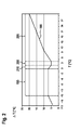
- FIG. 2 shows a diagram of a temperature profile 190, wherein the abscissa, the second temperature of the second medium 115 is plotted in degrees Celsius.
- the ordinate of the diagram plots the difference between the first temperature and the second temperature.
- the course of the diagram is stored in the memory 175 of the control device 105.
- the control device 105 controls the delivery rate of the fan device 70 in such a way that, based on the second temperature of the second medium 115, the delivery rate in FIG FIG. 2 shown curve of the difference of the first temperature and the second temperature applied over the second temperature sets.
- the in FIG. 2 shown temperature profile 190 has a first temperature range 195, a second temperature range 200 and a third temperature range 205. Furthermore, a transition temperature range 210 is provided between the first and second temperature ranges 195, 200.
- the first temperature range 195 extends substantially from -15 ° C to about 0 ° C.
- the transition temperature range 210 extends from about 0 ° C to 1.5 ° C.
- the second temperature range 200 extends from 1.5 ° C to 4 , 5 ° C.
- the third temperature range 205 extends from 4.5 ° C to well above 30 ° C.
- the temperature ranges 195, 200, 205, 210 are chosen differently.
- the second temperature range 200 and the transition temperature range 200, 210 are combined.
- the transition temperature range 210 may be formed particularly narrow with a particularly steep drop in the difference between the first temperature and the second temperature.
- the second temperature range 200 extends from 0 ° C to 6 ° C, preferably from 1 ° C to 5 ° C.
- the control device 105 continuously detects the pressures or temperatures detected by the pressure and temperature sensors 120, 125, 145, 155.
- the control device 105 controls the fan device 70 in terms of its delivery rate, in particular in terms of its rotational speed, such that upon detection of a second temperature signal correlating with a second temperature which is in the range of -15 ° to 0 °, a difference between the first and second temperatures, which is substantially constant over the first temperature range 195.
- first temperature range 195 which is between 5 ° C and 10 ° C, preferably between 6 ° C and 8 ° C, particularly advantageously 7 ° C, established.
- control device 105 is designed to control the fan device 70 in its capacity in the transition region 210 between the first temperature range 195 and the second temperature range 200 in such a way that the difference between the first temperature and the second temperature decreases from the first temperature range 195 toward the second temperature range 200.
- the control device 105 controls the fan device 70 in such a way that a temperature profile 190 over the difference of the first temperature and the second temperature over the first temperature is established, that the temperature profile 190 rises steadily. This can as the second temperature increases, the fan speed is reduced to reduce noise emissions from the fan means 70 for delivering the second medium 115 and to spared the drive motor 75 at a high ambient temperature corresponding to the second temperature.
- the temperature ranges 195, 200, 205, 210 are selected such that the temperature ranges 195, 200, 205, 210 adjoin one another.
- the second temperature range 200 is above the first temperature range 195 and the transition temperature range 210.
- the third temperature range 210 is above the second and first temperature ranges 195, 200.
- control device 105 is designed to steplessly control the speed of the fan device 70 over wide ranges of a rotational speed spectrum.
- a first threshold value for a second pressure in the second heat exchanger 65 is stored in the memory 175.
- the control device 105 continuously detects the second pressure signal of the second pressure sensor 155 and compares it with the first threshold stored in the memory 175. If the first pressure signal exceeds the first threshold value, the control device 105 activates the fan device 70 if it was deactivated.
- the control device 105 has a time detection device 215, which is designed to detect a time interval after activating the fan device 70. In this case, the control device 105 is configured to continue to operate the fan device 70 even when the first threshold value is undershot, provided that the predefined time interval, which is stored, for example, in the memory 175, has not yet expired.
- the above-described control of the fan device 70 to achieve the in FIG. 2 shown temperature profile 190 refers to a constant compressor power.
- the compressor power is varied by the control device 105 as well.
- the control device 105 is also designed, even with a varied Compressor performance the above temperature history 190, as in FIG. 2 shown to be achieved by regulating the delivery rate, in particular the rotational speed, of the fan device 70 as a function of the difference between the first temperature and the second temperature.
- the control device 105 is also designed to activate the time detection device 215 and the fan device 70 after deactivation of the compressor 15.
- the control device 105 activates the fan device 70 independently of the detected temperatures and pressures until the time detection device 215 signals the passage of a predefined tracking interval stored in the memory 175, for example two minutes after deactivation of the compressor 100.
- the control device 105 deactivates the fan device 70.
- the pressure in the heat pump cycle 10 compensated and on the other a simple de-icing effect on the second heat exchanger 65 can be ensured in heating mode. By deicing, for example, with ambient air, the energy required to operate the heat pump cycle 10 can be reduced in a simple manner.
- control device 105 is configured to switch on the fan device 70 only when a speed determined by the control device 105 for operating the fan device 70 corresponds to at least 20% of a nominal rotational speed of the fan device 70. Furthermore, the control device 105 switches off the fan device 70 only when a determined rotational speed of the fan device 70 is less than 11%. To protect the drive motor 75, the control device 105 does not control the rotational speed of the fan device 70 above 90% of the nominal rotational speed.
- the control device 105 can also have a quiet operating mode, in which the control device 105 is designed to increase the speed of the fan device 70 does not exceed 70% of the nominal speed of the fan device 70.
- control device 105 is designed, in the event of a sensor failure, for example for detecting the first or second temperature or the first or second pressure, to actuate the fan device 70 to 50% of the nominal speed in order to destroy the heat pump cycle 10 to avoid.
- the control device 105 controls the fan device 70 only when the compressor 15 has been activated and the second time interval after deactivation of the compressor 15 has not yet expired. If the second time interval of, for example, two minutes has already expired, the control device 105 likewise deactivates the fan device 70.
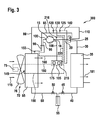
- FIG. 3 shows a schematic representation of a heat pump cycle 300 according to a second embodiment.
- the heat pump cycle 300 is substantially identical to that in FIG FIG. 1 formed heat pump cycle 10 is formed.
- the heat pump cycle 300 is operated in the opposite direction, so that the heat pump cycle 300 is in the operating state "cooling".
- the opposite operating direction is achieved by a second switching position of the 2/4 way valve 25.
- a first line 20 is fluidically connected via the 2/4 way valve 25 to the fifth line 80.
- the sixth line 85 is connected to the second line 30 via the 2/4 way valve.
- the second heat exchanger 65 serves as a condenser and the first heat exchanger 35 as an evaporator. Wrd the operating direction as in FIG. 3 shown opposite FIG. 1 turned over, so the third medium 181 is no longer over the first heat exchanger 35 as in FIG. 1 shown, heated but cooled.
- a third temperature sensor 216 is provided.
- the third temperature sensor 216 is connected to the control device 105 via an eighth connection 220.
- the third temperature sensor 216 provides a third temperature signal that corresponds to a third temperature of the first medium 110 in the first conduit 20.
- the control device 105 detects the third temperature signal of the third temperature sensor 216.
- the control device 105 is designed to control the delivery rate, in particular the rotational speed, of the fan device 70 as a function of the third temperature signal or the third temperature of the first medium 110 in the first line 20. This has the consequence that with increasing third temperature in the first line 20, the speed of the fan device 70th is increased to cool the first medium 110 in the second heat exchanger 65.
- the control device 105 is formed, the to FIG. 1 and 2 explained speed ranges of minimum speed and maximum speed for the fan device 70, not to exceed in this mode of operation to ensure reliable and quiet operation of the fan device 70. Furthermore, the control device 105 is designed to operate the fan device 70 at a speed of 50% of the nominal speed in the event of failure of the third temperature sensor 216 in order to avoid overheating of the first medium 110 in the second heat exchanger 65.
- a second threshold is stored in the memory 175 of the control device 105.
- the second threshold value corresponds to a second pressure in the second heat exchanger 65 during operation of the heat pump cycle 300 in the operating mode "cooling".
- the control device 105 is designed to detect the second pressure signal of the second pressure sensor 155. If the second pressure signal exceeds the second threshold value, the control device 105 activates the fan device 70 and operates it at least at the minimum speed of, for example, 20% over at least a period of one minute. Alternatively, it is also conceivable that the control device 105 controls the fan device 70 at a different rotational speed, in particular a higher rotational speed, optionally over a different period of time.
- FIG. 4 shows a schematic representation of a heat pump cycle 400 according to a third embodiment.
- the heat pump cycle 400 is substantially identical to that in FIG. 1 formed heat pump cycle 10 is formed.
- a wet injection 401 with a device 410 is provided.
- the device 410 is connected to the compressor 15 via an eighth line 405.
- a third throttle 420 is connected in parallel to the device 410.
- the device 410 is connected to the second throttle 50 via a ninth line 415.
- the device 410 and the third throttle 420 are further fluidly connected to the gas-liquid container 55 via a tenth conduit 425.
- Wet injection 401 may provide wet injection into the compressor 15.
- a liquid first medium 110 is passed directly to the compressor 15 via the eighth line 405.
- the third throttle 420 and the device 410 serve to meter a mass flow of the first medium 110 for injection into the compressor 15.
Landscapes
- Engineering & Computer Science (AREA)
- Mechanical Engineering (AREA)
- General Engineering & Computer Science (AREA)
- Physics & Mathematics (AREA)
- Thermal Sciences (AREA)
- Air Conditioning Control Device (AREA)
- Heat-Pump Type And Storage Water Heaters (AREA)
Abstract
Die Erfindung betrifft ein Verfahren zum Steuern einer Lüftereinrichtung eines Verdampfers eines Wärmepumpenkreislaufs sowie einen Wärmepumpenkreislauf mit einem Kompressor, einer Steuereinrichtung und einem Verdampfer, wobei der Kompressor ein erstes Medium aus dem Verdampfer pumpt, wobei eine Lüftereinrichtung vorgesehen ist, die ausgebildet ist, ein zweites Medium für den Verdampfer zu fördern, wobei ein erster Temperatursensor vorgesehen ist, wobei der erste Temperatursensor eine erste Temperatur des ersten Mediums zwischen dem Verdampfer und dem Kompressor misst, wobei ein zweiter Temperatursensor vorgesehen ist, wobei der zweite Temperatursensor eine zweite Temperatur des zweiten Mediums stromaufwärtsseitig des Verdampfers misst, wobei die Steuereinrichtung eine Förderleistung der Lüftereinrichtung in Abhängigkeit einer Differenz aus der ersten Temperatur und der zweiten Temperatur steuert.The invention relates to a method for controlling a fan device of an evaporator of a heat pump cycle and a heat pump cycle with a compressor, a control device and an evaporator, wherein the compressor pumps a first medium from the evaporator, wherein a fan device is provided, which is formed a second medium for the evaporator, wherein a first temperature sensor is provided, wherein the first temperature sensor measures a first temperature of the first medium between the evaporator and the compressor, wherein a second temperature sensor is provided, the second temperature sensor is a second temperature of the second medium upstream of the Evaporator measures, wherein the control device controls a delivery rate of the fan device in response to a difference between the first temperature and the second temperature.
Description
Die Erfindung betrifft ein Verfahren zum Steuern einer Lüftereinrichtung eines Verdampfers eines Wärmepumpenkreislaufs gemäß Patentanspruch 1 und Patentanspruch 9 und einen Wärmepumpenkreislauf mit einem Kompressor und einem Verdampfer gemäß Patentanspruch 11 und Patentanspruch 12.The invention relates to a method for controlling a fan device of an evaporator of a heat pump cycle according to claim 1 and claim 9 and a heat pump cycle with a compressor and an evaporator according to claim 11 and claim 12.
Es sind Wärmepumpenkreisläufe bekannt, die einen Kompressor und einen Verdampfer aufweisen. Der Verdampfer ist fluidisch über ein erstes Medium mit dem Kompressor verbunden. An dem Verdampfer ist ein Lüfter vorgesehen, der ausgebildet ist, ein zweites Medium an den Verdampfer zu fördern, um einen Wärmeaustausch an dem Verdampfer zwischen dem ersten Medium und dem zweiten Medium zu erreichen. Der Lüfter dient dazu, den Wärmeaustausch zwischen den beiden Medien zu forcieren. Dabei kann der Lüfter, insbesondere eine Drehzahl der Lüftereinrichtung, in Abhängigkeit der Temperatur des zweiten Mediums angesteuert werden. Aufgrund des breiten Temperaturspektrums des zweiten Mediums, das beispielsweise die Umgebungsluft sein kann, kann das Betriebsverhalten in bestimmten Temperaturbereichen negativ beeinflusst bei dieser Steuerungsmethode sein.Heat pump circuits are known which include a compressor and an evaporator. The evaporator is fluidly connected via a first medium to the compressor. Provided on the evaporator is a fan configured to deliver a second medium to the evaporator to achieve heat exchange at the evaporator between the first medium and the second medium. The fan is used to force the heat exchange between the two media. In this case, the fan, in particular a rotational speed of the fan device, can be controlled as a function of the temperature of the second medium. Due to the broad temperature spectrum of the second medium, which may be, for example, the ambient air, the performance in certain temperature ranges may be adversely affected in this control method.
Es ist Aufgabe der Erfindung, ein verbessertes Verfahren zum Steuern einer Lüftereinrichtung eines Wärmetauschers eines Wärmepumpenkreislaufs bereitzustellen. Ferner besteht die Aufgabe der Erfindung darin, einen verbesserten Wärmepumpenkreislauf bereitzustellen.It is an object of the invention to provide an improved method for controlling a fan device of a heat exchanger of a heat pump cycle. Furthermore, the object of the invention is to provide an improved heat pump cycle.
Die Aufgabe der Erfindung wird gemäß Patentanspruch 1 gelöst. Vorteilhafte Ausführungsformen sind in den abhängigen Ansprüchen angegeben.The object of the invention is achieved according to claim 1. Advantageous embodiments are given in the dependent claims.
Erfindungsgemäß wurde erkannt, dass ein verbessertes Verfahren zur Steuerung einer Lüftereinrichtung eines Verdampfers eines Wärmepumpenkreislaufs, aufweisend einen Kompressor, der ein erstes Medium aus dem Verdampfer fördert, und die Lüftereinrichtung, die ein zweites Medium zur Umströmung des Verdampfers fördert, dadurch bereitgestellt werden kann, dass eine erste Temperatur des ersten Mediums zwischen dem Verdampfer und dem Kompressor gemessen wird, wobei eine zweite Temperatur des zweiten Mediums stromaufwärtsseitig des Verdampfers gemessen wird. Ferner wird eine Förderleistung der Lüftereinrichtung in Abhängigkeit einer Differenz aus der ersten Temperatur und der zweiten Temperatur gesteuert.According to the invention, it has been recognized that an improved method for controlling a fan device of an evaporator of a heat pump cycle, comprising a compressor, which conveys a first medium from the evaporator, and the fan device, which conveys a second medium for flowing around the evaporator, can be provided by a first temperature of the first medium is measured between the evaporator and the compressor, wherein a second temperature of the second medium is measured upstream of the evaporator. Furthermore, a delivery rate of the fan device is controlled in dependence on a difference between the first temperature and the second temperature.
Diese Ausgestaltung hat den Vorteil, dass sie bei bereits existierenden oder neuen Wärmepumpenkreisläufen eingesetzt werden kann. Zudem hat die vorgeschlagene Lösung den Vorteil, dass ein verbessertes Betriebsverhalten insbesondere durch stark unterschiedliche Luftfeuchtigkeiten bereitgestellt wird. Ferner ist das Betriebsverhalten im Kühlkreislauf stabiler und ebenso wird ein Vereisen des Verdampfers reduziert. Dadurch kann ein zeitlicher Abstand zwischen einzelnen Enteisungsvorgängen vergrößert werden.This embodiment has the advantage that it can be used in already existing or new heat pump cycles. In addition, the proposed solution has the advantage that an improved operating behavior is provided in particular by greatly different humidities. Furthermore, the performance in the refrigeration cycle is more stable and also icing of the evaporator is reduced. This can increase a time interval between individual defrosting operations.
In einer weiteren Ausführungsform wird die Förderleistung derart gesteuert, dass die Differenz der ersten Temperatur und der zweiten Temperatur über die zweite Temperatur in wenigstens einem Temperaturbereich der zweiten Temperatur konstant ist. Auf diese Weise kann eine einfache Steuerung der Drehzahl der Lüftereinrichtung bereitgestellt werden.In a further embodiment, the delivery rate is controlled such that the difference between the first temperature and the second temperature is constant over the second temperature in at least one temperature range of the second temperature. In this way, a simple control of the speed of the fan device can be provided.
In einer weiteren Ausführungsform ist die Differenz der ersten Temperatur und der zweiten Temperatur in dem Temperaturbereich der zweiten Temperatur 5° bis 10 °C, vorzugsweise 6° bis 8 °C, besonders vorteilhafterweise 7 °C.In a further embodiment, the difference of the first temperature and the second temperature in the temperature range of the second temperature is 5 ° to 10 ° C, preferably 6 ° to 8 ° C, most preferably 7 ° C.
In einer weiteren Ausführungsform ist die Differenz der ersten Temperatur und der zweiten Temperatur in einem ersten Temperaturbereich größer, insbesondere um 2 °C größer, als die Differenz der ersten Temperatur und der zweiten Temperatur in einem zweiten Temperaturbereich ist, wobei der zweite Temperaturbereich oberhalb des ersten Temperaturbereichs angeordnet ist. Dadurch kann ein Vereisen des Verdampfers besonders zuverlässig vermieden werden.In a further embodiment, the difference of the first temperature and the second temperature in a first temperature range is greater, in particular by 2 ° C greater than the difference of the first temperature and the second temperature in a second temperature range, wherein the second temperature range is arranged above the first temperature range. As a result, icing of the evaporator can be avoided particularly reliably.
In einer weiteren Ausführungsform steigt die Differenz der ersten Temperatur und der zweiten Temperatur in einem dritten Temperaturbereich der zweiten Temperatur mit steigender zweiter Temperatur, wobei der dritte Temperaturbereich oberhalb des zweiten und des ersten Temperaturbereichs angeordnet ist. Dadurch kann im dritten Temperaturbereich eine Förderleistung der Lüftereinrichtung reduziert werden, so dass ein Antrieb der Lüftereinrichtung geschont wird.In a further embodiment, the difference of the first temperature and the second temperature increases in a third temperature range of the second temperature with increasing second temperature, wherein the third temperature range is arranged above the second and the first temperature range. As a result, in the third temperature range, a delivery rate of the fan device can be reduced, so that a drive of the fan device is spared.
Besonders vorteilhaft ist, wenn die Differenz der ersten Temperatur und der zweiten Temperatur im dritten Temperaturbereich stetig steigt.It is particularly advantageous if the difference of the first temperature and the second temperature in the third temperature range increases steadily.
In einer weiteren Ausführungsform erstreckt sich der erste Temperaturbereich im Wesentlichen von -15 °C bis 0 °C, wobei der zweite Temperaturbereich sich von 0 °C bis 6 °C, vorzugsweise von 1° bis 5°C, besonders vorteilhafterweise von 1,5 °C bis 4,5 °C, erstreckt. Diese Bereichswahl hat sich als besonders vorteilhaft hinsichtlich der Vermeidung von Eisbildung am Verdampfer herausgestellt.In a further embodiment, the first temperature range extends substantially from -15 ° C to 0 ° C, the second temperature range being from 0 ° C to 6 ° C, preferably from 1 ° to 5 ° C, more preferably from 1.5 ° C to 4.5 ° C, extends. This range has proven to be particularly advantageous in terms of avoiding icing on the evaporator.
Der Wärmepumpenkreislauf wird vor einer Beschädigung geschützt, wenn ein Druck des ersten Mediums im Verdampfer überwacht wird, wobei der erfasste Druck mit einem vordefinierten Schwellenwert verglichen wird, wobei bei Unterschreiten des erfassten Drucks im Verdampfer die Lüftereinrichtung aktiviert wird.The heat pump circuit is protected from damage when monitoring a pressure of the first medium in the evaporator, wherein the detected pressure is compared with a predefined threshold, wherein when the pressure falls below the detected pressure in the evaporator, the fan device is activated.
Die Aufgabe wird aber auch durch ein Verfahren gemäß Patentanspruch 9 gelöst. Vorteilhafte Ausführungsformen sind in den abhängigen Ansprüchen angegeben.The task is also solved by a method according to
Erfindungsgemäß wurde erkannt, dass ein verbessertes Verfahren zur Steuerung einer Lüftereinrichtung eines Kondensators eines Wärmepumpenkreislaufs, aufweisend einen Kompressor, der ein erstes Medium zu dem Kondensator pumpt, und die Lüftereinrichtung, die ein zweites Medium zur Umströmung des Kondensators fördert, dadurch bereitgestellt werden kann, dass eine Temperatur des ersten Mediums ausgangsseitig des Kompressors zwischen Kompressor und Kondensator gemessen wird, wobei eine Förderleistung der Lüftereinrichtung in Abhängigkeit der Temperatur des ersten Mediums gesteuert wird.According to the invention, it has been recognized that an improved method for controlling a fan means of a condenser of a heat pump cycle, comprising a compressor which pumps a first medium to the condenser, and the fan means, which conveys a second medium to flow around the condenser, can be provided a temperature of the first medium on the output side of the compressor between the compressor and Capacitor is measured, wherein a delivery rate of the fan device is controlled in dependence on the temperature of the first medium.
Auf diese Weise wird sichergestellt, dass eine hinreichend große Masse des zweiten Mediums dem Kondensator zugeführt wird, um zwischen dem Verdampfer und dem zweiten Medium einen hinreichend großen Wärmeaustausch stattfinden zu lassen, um einen sicheren Betrieb des Wärmepumpenkreislaufs sicherzustellen.In this way it is ensured that a sufficiently large mass of the second medium is supplied to the condenser to allow a sufficiently large heat exchange to take place between the evaporator and the second medium in order to ensure safe operation of the heat pump cycle.
In einer Ausführungsform der Erfindung wird ein Druck des ersten Mediums in dem Kondensator überwacht, wobei der erfasste Druck mit einem vordefinierten Schwellenwert verglichen wird, wobei bei Überschreiten des erfassten Drucks im Kondensator die Lüftereinrichtung aktiviert wird. Auf diese Weise wird sichergestellt, dass das erste Medium den Verdampfer gasförmig verlässt.In one embodiment of the invention, a pressure of the first medium is monitored in the condenser, wherein the detected pressure is compared with a predefined threshold, wherein when the detected pressure in the condenser is exceeded, the fan device is activated. In this way it is ensured that the first medium leaves the evaporator in gaseous form.
Die Aufgabe wird aber auch durch einen Wärmepumpenkreislauf gemäß Patentanspruch 11 gelöst. Vorteilhafte Ausführungsformen sind in den abhängigen Ansprüchen angegeben.The task is also solved by a heat pump cycle according to claim 11. Advantageous embodiments are given in the dependent claims.
Erfindungsgemäß wurde erkannt, dass ein verbesserter Wärmepumpenkreislauf dadurch bereitgestellt werden kann, dass der Wärmepumpenkreislauf einen Kompressor, eine Steuereinrichtung und einen Verdampfer umfasst, wobei der Kompressor ein erstes Medium aus dem Verdampfer pumpt. Ferner ist eine Lüftereinrichtung vorgesehen, die ausgebildet ist, ein zweites Medium für den Verdampfer zu fördern. Des Weiteren ist ein erster Temperatursensor vorgesehen, wobei der erste Temperatursensor eine erste Temperatur des ersten Mediums zwischen dem Verdampfer und dem Kompressor misst. Ferner ist ein zweiter Temperatursensor vorgesehen, wobei der zweite Temperatursensor eine zweite Temperatur des zweiten Mediums stromaufwärtsseitig des Verdampfers misst. Die Steuereinrichtung steuert eine Förderleistung der Lüftereinrichtung in Abhängigkeit einer Differenz aus der ersten Temperatur und der zweiten Temperatur.According to the invention, it has been recognized that an improved heat pump cycle can be provided by the heat pump cycle comprising a compressor, a controller, and an evaporator, wherein the compressor pumps a first medium from the evaporator. Furthermore, a fan device is provided, which is designed to convey a second medium for the evaporator. Furthermore, a first temperature sensor is provided, wherein the first temperature sensor measures a first temperature of the first medium between the evaporator and the compressor. Furthermore, a second temperature sensor is provided, wherein the second temperature sensor measures a second temperature of the second medium upstream of the evaporator. The control device controls a delivery rate of the fan device as a function of a difference between the first temperature and the second temperature.
Auf diese Weise wird ein zuverlässigeres Betriebsverhalten des Wärmepumpenkreislaufs im Heizbetrieb bei unterschiedlichsten Betriebsbedingungen gewährleistet. Insbesondere wird bei unterschiedlichen Luftfeuchtigkeiten eine Vereisung des Wärmetauschers reduziert.In this way, a more reliable operating behavior of the heat pump cycle is guaranteed in the heating operation under different operating conditions. In particular, icing of the heat exchanger is reduced at different humidities.
Besonders vorteilhaft ist, wenn das zweite Medium Luft ist.It is particularly advantageous if the second medium is air.
Die Aufgabe wird aber auch durch einen Wärmepumpenkreislauf gemäß Patentanspruch 12 gelöst. Vorteilhafte Ausführungsformen sind in den abhängigen Ansprüchen angegeben.The task is also solved by a heat pump cycle according to
Erfindungsgemäß wurde erkannt, dass ein verbesserter Wärmepumpenkreislauf dadurch bereitgestellt werden kann, dass der Wärmepumpenkreislauf einen Kompressor, eine Steuereinrichtung und einen Kondensator umfasst, wobei der Kompressor ein erstes Medium in den Kondensator pumpt, wobei eine Lüftereinrichtung vorgesehen ist, die ausgebildet ist, ein zweites Medium für den Kondensator zu fördern. Ferner ist ein Temperatursensor vorgesehen, wobei der Temperatursensor eine Temperatur des ersten Mediums zwischen dem Kondensator und dem Kompressor misst, wobei die Steuereinrichtung eine Förderleistung der Lüftereinrichtung in Abhängigkeit der gemessenen Temperatur steuert.According to the invention, it has been recognized that an improved heat pump cycle can be provided in that the heat pump cycle comprises a compressor, a controller and a condenser, the compressor pumping a first medium into the condenser, wherein a fan means is provided, which is a second medium to promote the condenser. Furthermore, a temperature sensor is provided, wherein the temperature sensor measures a temperature of the first medium between the condenser and the compressor, wherein the control device controls a delivery rate of the fan device as a function of the measured temperature.
Auf diese Weise kann insbesondere im Kühlbetrieb ein zuverlässiges Betriebsverhalten des Wärmepumpenkreislaufs gewährleistet werden.In this way, a reliable operating behavior of the heat pump cycle can be ensured, especially in the cooling mode.
Besonders vorteilhaft ist, wenn das zweite Medium Luft ist.It is particularly advantageous if the second medium is air.
In einer weiteren Ausführungsform umfasst die Lüftereinrichtung einen Antriebsmotor und einen Lüfterrotor, der mit dem Antriebsmotor gekoppelt ist, wobei die Förderleitung der Lüftereinrichtung über eine Drehzahl des Antriebsmotors gesteuert wird. Dadurch kann die Förderleistung besonders einfach gesteuert werden.In a further embodiment, the fan device comprises a drive motor and a fan rotor, which is coupled to the drive motor, wherein the delivery line of the fan device is controlled via a rotational speed of the drive motor. As a result, the delivery rate can be controlled particularly easily.
Nachfolgend wird die Erfindung anhand von Figuren näher erläutert. Dabei zeigen:
- Fig. 1
- eine schematische Darstellung eines Wärmepumpenkreislaufs gemäß einer ersten Ausführungsform;
- Fig. 2
- ein Diagramm für einen Temperaturverlauf;
- Fig. 3
- eine schematische Darstellung eines Wärmepumpenkreislaufs gemäß einer zweiten Ausführungsform; und
- Fig. 4
- eine schematische Darstellung eines Wärmepumpenkreislaufs gemäß einer dritten Ausführungsform.
- Fig. 1
- a schematic representation of a heat pump cycle according to a first embodiment;
- Fig. 2
- a diagram for a temperature profile;
- Fig. 3
- a schematic representation of a heat pump cycle according to a second embodiment; and
- Fig. 4
- a schematic representation of a heat pump cycle according to a third embodiment.
Die in
Der Kompressor 15 ist mit einer Steuereinrichtung 105 über eine erste Verbindung 106 verbunden. Die Steuereinrichtung 105 ist dabei ausgebildet, den Kompressor 15 je nach Leistungsanforderung mit elektrischer Leistung zu versorgen und den Kompressor 15 anzusteuern. Im Folgenden werden Verbindungen, die eine elektrische Verbindung zwischen einzelnen Komponenten des Wärmepumpenkreislaufs 10 bereitstellen, strichliert dargestellt, um eine bessere Unterscheidung zwischen den elektrischen Verbindungen und den fluidführenden Leitungen 20, 30, 40, 60, 80, 85, 95 zu ermöglichen.The
Die Lüftereinrichtung 70 ist an dem zweiten Wärmetauscher 65 angeordnet. Die Lüftereinrichtung 70 im Betrieb fördert ein zweites Medium 115, vorzugsweise Luft, an den zweiten Wärmetauscher 65, so dass an dem zweiten Wärmetauscher 65 ein Wärmeaustausch zwischen dem ersten Medium 110 und dem zweiten Medium 115 erfolgt. Selbstverständlich kann die Lüftereinrichtung auch an einer anderen Position angeordnet sein, um das zweite Medium zum zweiten Wärmetauscher 65 zu fördern.The
Im Wärmepumpenkreislauf 10 sind zahlreiche Sensoren zum Erfassen einer Temperatur oder eines Drucks des ersten oder des zweiten Mediums 110, 115 vorgesehen. Dabei ist ein erster Temperatursensor 120 und ein erster Drucksensor 125 an der sechsten Leitung 85 vorgesehen, um eine erste Temperatur bzw. einen ersten Druck des ersten Mediums 110 eingangsseitig vor dem Kompressor 15 in der sechsten Leitung 85 zu erfassen. Der erste Temperatursensor 120 ist dabei über eine zweite Verbindung 130 mit der Steuereinrichtung 105 verbunden. Der erste Drucksensor 125 ist über eine dritte Verbindung 140 mit der Steuereinrichtung 105 verbunden.In the
Ferner ist ein zweiter Temperatursensor 145 vorgesehen, der zwischen der Lüftereinrichtung 70 und dem zweiten Wärmetauscher 65, also stromaufwärtsseitig des zweiten Wärmetauschers angeordnet ist, um eine Temperatur des zweiten Mediums 115 zu erfassen. Selbstverständlich ist auch denkbar, dass der zweite Temperatursensor 145 linksseitig in
Ferner ist in dem zweiten Wärmetauscher 65 ein zweiter Drucksensor 155 vorgesehen. Der zweite Drucksensor 155 ist über eine fünfte Verbindung 160 mit der Steuereinrichtung 105 verbunden. Die Druck- und Temperatursensoren 120, 125, 145, 155 stellen ein zum Druck bzw. zur Temperatur korrelierendes Druck- bzw. Temperatursignal über die jeweiligen Verbindungen 130, 140, 150, 160 der Steuereinrichtung 105 bereit. Der Antriebsmotor 75 der Lüftereinrichtung 70 ist über eine sechste Verbindung 180 mit der Steuereinrichtung 105 verbunden. Die Steuereinrichtung 105 weist ferner einen Speicher 175 auf.Further, in the
Der in
Über die dritte Leitung 40 wird das erste Medium 110 zu der ersten Drossel 45 geführt. Über die erste Drossel 45 wird eine Entspannung des ersten Mediums 110 in den Gas-Flüssigkeitsbehälter 55 gesteuert. Dabei weist das erste Medium 110 nach der ersten Drossel 45 einen geringeren Druck als vor der ersten Drossel 45 auf. Mittels der zweiten Drossel 50 wird ein Abfluss aus dem Gas-Flüssigkeitsbehälter 55 gesteuert.Via the
Das erste Medium 110 fließt als unterkühlte Flüssigkeit in der vierten Leitung 60 in den zweiten Wärmetauscher 65. Im Heizbetrieb wird dem ersten Medium 110 Wärme aus dem zweiten Medium 115 zugeführt. Um eine besonders große Wärmezuführung zu erreichen, fördert die Lüftereinrichtung 70 das zweite Medium 115 an den zweiten Wärmetauscher 65. Durch die Zuführung der Wärme bleibt zwar der Druck des ersten Mediums 110 im zweiten Wärmetauscher 65 im Wesentlichen gleich, jedoch erhöht sich die Temperatur. Dabei wird im zweiten Wärmetauscher 65 das erste Medium 110 so weit erwärmt, dass das erste Medium 110 im zweiten Wärmetauscher 65 verdampft wird und den zweiten Wärmetauscher 65 im überhitzten Gaszustand über die fünfte Leitung 80 verlässt.The
Über die fünfte Leitung 80 wird das erste Medium dem 2/4 Wegeventil 25 zugeführt und wird von dort aus in den Flüssigkeitsabscheider 90 über die sechste Leitung 85 geführt. Sollten sich noch einzelne Flüssigkeitstropfen in dem überhitzten Gas des ersten Mediums 110 befinden, werden diese im Flüssigkeitsabscheider 90 abgeschieden. Das überhitzte Gas des ersten Mediums 110 wird über die siebte Leitung 95 an die Eingangsseite 100 zur abermaligen Kompression durch den Kompressor 15 dem Kompressor 15 zugeführt, der dieses dann abermals komprimiert. Auf diese Weise ist der Wärmepumpenkreislauf 10 geschlossen.Via the
Die Sensoren 120, 125, 155, 145 stellen der Steuereinrichtung 105 ein korrespondierendes Sensorsignal bereit. Die Steuereinrichtung 105 erfasst dabei ein erstes Temperatursignal des ersten Temperatursensors 120, das mit einer ersten Temperatur in der sechsten Leitung 85 des ersten Mediums 110 korrespondiert. Ferner erfasst die Steuereinrichtung 105 ein erstes Drucksignal des ersten Drucksensors 125, das mit einem ersten Druck des ersten Mediums 110 in der sechsten Leitung 85 korreliert. Die Steuereinrichtung 105 erfasst weiter ein zweites Temperatursignal des zweiten Temperatursensors 145, das mit einer zweiten Temperatur des zweiten Mediums 115 korreliert. Des Weiteren erfasst die Steuereinrichtung 105 ein zweites Drucksignal des zweiten Drucksensors 155, das mit dem Druck im zweiten Wärmetauscher 65 korreliert.The
Die Steuereinrichtung 105 bildet eine Differenz aus der ersten Temperatur des ersten Mediums 110 in der sechsten Leitung 85 und der zweiten Temperatur des zweiten Mediums 115 am zweiten Wärmetauscher 65. Die Steuereinrichtung 105 steuert in Abhängigkeit der Differenz aus der ersten Temperatur und der zweiten Temperatur über die sechste Verbindung 180 den Antriebsmotor 75 der Lüftereinrichtung 70 an und regelt in Abhängigkeit der Differenz der ersten Temperatur und der zweiten Temperatur eine Förderleistung der Lüftereinrichtung. Dabei korreliert die Förderleistung mit einer Drehzahl des Lüfterrotors 76 bzw. des Antriebsmotors 76. Die Förderleistung korrespondiert aber auch mit einem Massenstrom des dem zweiten Wärmetauschers 65 zugeführten zweiten Mediums. Dadurch kann auf einfache Weise ein Wärmeaustausch am zweiten Wärmetauscher 65 zwischen dem zweiten Medium 115 und dem ersten Medium 110 gesteuert werden.The
Der in
Der erste Temperaturbereich 195 erstreckt sich im Wesentlichen von -15 °C bis etwa 0 °C.Der Übergangstemperaturbereich 210 erstreckt sich von etwa 0 °C bis 1,5 °C.Der zweite Temperaturbereich 200 erstreckt sich von 1,5 °C bis 4,5 °C. Der dritte Temperaturbereich 205 erstreckt sich von 4,5 °C bis weit über 30 °C. Selbstverständlich ist auch denkbar, dass die Temperaturbereiche 195, 200, 205, 210 andersartig gewählt sind. So ist insbesondere denkbar, dass der zweite Temperaturbereich 200 und der Übergangstemperaturbereich 200, 210 zusammengefasst sind. Dabei kann beispielsweise der Übergangstemperaturbereich 210 besonders schmal mit einem besonders steilen Abfall der Differenz aus der ersten Temperatur und der zweiten Temperatur ausgebildet sein. So ist denkbar, dass der zweite Temperaturbereich 200 sich von 0 °C bis 6 °C, vorzugsweise von 1 °C bis 5 °C, erstreckt.The
Die Steuereinrichtung 105 erfasst kontinuierlich die von den Druck- und Temperatursensoren 120, 125, 145, 155 erfassten Drücke bzw. Temperaturen. Dabei steuert die Steuereinrichtung 105 die Lüftereinrichtung 70 in ihrer Förderleistung, insbesondere in ihrer Drehzahl derartig an, dass bei Erfassen eines zweiten Temperatursignals, das mit einer zweiten Temperatur korreliert, die im Bereich von -15° bis 0° liegt, sich eine Differenz zwischen der ersten und der zweiten Temperatur einstellt, die über dem ersten Temperaturbereich 195 im Wesentlichen konstant ist.The
Besonders vorteilhaft ist hierbei, wenn sich in dem ersten Temperaturbereich 195 eine Differenz aus der ersten Temperatur und der zweiten Temperatur einstellt, die zwischen 5 °C und 10 °C, vorzugsweise zwischen 6 °C und 8 °C, besonders vorteilhafterweise 7 °C, einstellt. Dadurch kann bei niedrigen Temperaturen ein Vereisen des zweiten Wärmetauschers 65 vermieden werden.In this case, it is particularly advantageous if a difference between the first temperature and the second temperature sets in the
Ferner steuert die Steuereinrichtung 105 die Lüftereinrichtung 70 in ihrer Förderleistung, insbesondere in ihrer Drehzahl derartig an, dass sich im zweiten Temperaturbereich 200 eine Differenz aus der ersten Temperatur und der zweiten Temperatur einstellt, die sich etwa bei 5 °C, also 2 °C geringer als im ersten Temperaturbereich 195, einstellt. Dabei ist auch im zweiten Temperaturbereich 200 wie im ersten Temperaturbereich 195 über die erste Temperatur die Differenz aus der ersten Temperatur und der zweiten Temperatur im Wesentlichen konstant.Furthermore, the
Je nach im Speicher 175 abgelegter Breite des zweiten Temperaturbereichs 200 ist die Steuereinrichtung 105 ausgebildet, im Übergangsbereich 210 zwischen dem ersten Temperaturbereich 195 und dem zweiten Temperaturbereich 200 die Lüftereinrichtung 70 in ihrer Förderleistung derartig anzusteuern, dass die Differenz aus der ersten Temperatur und der zweiten Temperatur von dem ersten Temperaturbereich 195 hin zum zweiten Temperaturbereich 200 abfällt.Depending on the width of the
Im dritten Temperaturbereich 205 steuert die Steuereinrichtung 105 die Lüftereinrichtung 70 derartig an, dass sich ein Temperaturverlauf 190 über der Differenz der ersten Temperatur und der zweiten Temperatur über die erste Temperatur einstellt, dass der Temperaturverlauf 190 stetig steigt. Dadurch kann mit Zunehmen der zweiten Temperatur die Lüftereinrichtungsdrehzahl reduziert werden, so dass zum einen Lärmemissionen durch die Lüftereinrichtung 70 zur Förderung des zweiten Mediums 115 reduziert werden und zum anderen der Antriebsmotor 75 bei einer hohen Umgebungstemperatur, die der zweiten Temperatur entspricht, geschont wird.In the
Die Temperaturbereiche 195, 200, 205, 210 sind derartig gewählt, dass die Temperaturbereiche 195, 200, 205, 210 aneinander angrenzen. Somit liegt der zweite Temperaturbereich 200 oberhalb des ersten Temperaturbereichs 195 und des Übergangstemperaturbereichs 210. Der dritte Temperaturbereich 210 liegt oberhalb des zweiten und des ersten Temperaturbereichs 195, 200.The temperature ranges 195, 200, 205, 210 are selected such that the temperature ranges 195, 200, 205, 210 adjoin one another. Thus, the
Um einen zuverlässigen und leisen Betrieb des Wärmepumpenkreislaufs 10, insbesondere der Lüftereinrichtung 70 zu gewährleisten, ist die Steuereinrichtung 105 ausgebildet, die Drehzahl der Lüftereinrichtung 70 über weite Bereiche eines Drehzahlspektrums stufenlos zu regeln.In order to ensure a reliable and quiet operation of the
Ferner ist in dem Speicher 175 ein erster Schwellenwert für einen zweiten Druck im zweiten Wärmetauscher 65 hinterlegt. Die Steuereinrichtung 105 erfasst kontinuierlich das zweite Drucksignal des zweiten Drucksensors 155 und vergleicht es mit dem im Speicher 175 abgelegten ersten Schwellenwert. Überschreitet das erste Drucksignal den ersten Schwellenwert, so aktiviert die Steuereinrichtung 105 die Lüftereinrichtung 70, sofern dieser deaktiviert war. Um ein kurzfristiges Ein- und Ausschalten und somit eine mögliche Zerstörung des Antriebsmotors 75 zu vermeiden, weist die Steuereinrichtung 105 eine Zeiterfassungseinrichtung 215 auf, die ausgebildet ist, ein Zeitintervall nach Aktivieren der Lüftereinrichtung 70 zu erfassen. Dabei ist die Steuereinrichtung 105 ausgebildet, die Lüftereinrichtung 70 auch bei Unterschreiten des ersten Schwellenwerts weiter zu betreiben, sofern das vordefinierte Zeitintervall, das beispielsweise in dem Speicher 175 abgelegt ist, noch nicht abgelaufen ist.Furthermore, a first threshold value for a second pressure in the
Die oben beschriebene Ansteuerung der Lüftereinrichtung 70 zur Erzielung des in
Die Steuereinrichtung 105 ist ferner ausgebildet, nach Deaktivierung des Kompressors 15 die Zeiterfassungseinrichtung 215 und die Lüftereinrichtung 70 zu aktivieren. Dabei lässt die Steuereinrichtung 105 die Lüftereinrichtung 70 solange unabhängig von den erfassten Temperaturen und Drücken aktiviert, bis die Zeiterfassungseinrichtung 215 den Ablauf eines vordefinierten und im Speicher 175 abgelegten Nachlaufintervalls, beispielsweise zwei Minuten nach Deaktivierung des Kompressors 100, signalisiert. Nach Ablauf des Nachlaufintervalls deaktiviert die Steuereinrichtung 105 die Lüftereinrichtung 70. Dadurch kann zum einen der Druck im Wärmepumpenkreislauf 10 ausgeglichen und zum anderen ein einfacher Enteisungseffekt am zweiten Wärmetauscher 65 im Heizbetrieb gewährleistet werden. Durch das Enteisen beispielsweise mit Umgebungsluft, kann der Energieaufwand zum Betrieb des Wärmepumpenkreislaufs 10 auf einfache Weise reduziert werden.The
In der Ausführungsform ist die Steuereinrichtung 105 ausgebildet, die Lüftereinrichtung 70 erst einzuschalten, wenn eine durch die Steuereinrichtung 105 ermittelte Drehzahl zum Betrieb der Lüftereinrichtung 70 wenigstens 20 % einer Nominaldrehzahl der Lüftereinrichtung 70 entspricht. Ferner schaltet die Steuereinrichtung 105 die Lüftereinrichtung 70 erst dann ab, wenn eine ermittelte Drehzahl der Lüftereinrichtung 70 kleiner 11 % ist. Zur Schonung des Antriebsmotors 75 steuert die Steuereinrichtung 105 die Drehzahl der Lüftereinrichtung 70 nicht über 90 % der Nominaldrehzahl. Die Steuereinrichtung 105 kann dabei auch einen leisen Betriebsmodus aufweisen, bei dem die Steuereinrichtung 105 ausgebildet ist, die Drehzahl der Lüftereinrichtung 70 nicht über 70 % der Nominaldrehzahl der Lüftereinrichtung 70 zu steigern.In the embodiment, the
In der Ausführungsform ist die Steuereinrichtung 105 ausgebildet, bei einem Sensorausfall, beispielsweise zur Erfassung der ersten oder zweiten Temperatur oder des ersten oder zweiten Drucks, die Lüftereinrichtung 70 auf 50 % der Nominaldrehzahl anzusteuern, um eine Zerstörung des Wärmepumpenkreislaufs 10 zu vermeiden. Die Steuereinrichtung 105 steuert dabei die Lüftereinrichtung 70 nur dann an, wenn der Kompressor 15 aktiviert wurde und das zweite Zeitintervall nach Deaktivierung des Kompressors 15 noch nicht abgelaufen ist. Ist das zweite Zeitintervall von beispielsweise zwei Minuten bereits abgelaufen, so deaktiviert die Steuereinrichtung 105 ebenso die Lüftereinrichtung 70.In the embodiment, the
In
Zusätzlich zu dem in
Die Steuereinrichtung 105 ist dabei ausgebildet, die zu
Im Speicher 175 der Steuereinrichtung 105 ist ein zweiter Schwellenwert abgelegt. Der zweite Schwellenwert entspricht dabei einem zweiten Druck im zweiten Wärmetauscher 65 bei Betrieb des Wärmepumpenkreislaufs 300 im Betriebsmodus "Kühlen". Die Steuereinrichtung 105 ist dabei ausgebildet, das zweite Drucksignal des zweiten Drucksensors 155 zu erfassen. Überschreitet das zweite Drucksignal den zweiten Schwellenwert, so aktiviert die Steuereinrichtung 105 die Lüftereinrichtung 70 und betreibt diesen zumindest mit der Minimaldrehzahl von beispielsweise 20 % über wenigstens einen Zeitraum von einer Minute. Alternativ ist auch denkbar, dass die Steuereinrichtung 105 die Lüftereinrichtung 70 mit einer anderen Drehzahl, insbesondere einer höheren Drehzahl gegebenenfalls über einen anderen Zeitraum ansteuert.In the
Claims (14)
Priority Applications (1)
| Application Number | Priority Date | Filing Date | Title |
|---|---|---|---|
| EP15197807.9A EP3029330A1 (en) | 2013-07-16 | 2014-06-10 | Method for controlling a fan device of an condenser of a heat pump circuit |
Applications Claiming Priority (1)
| Application Number | Priority Date | Filing Date | Title |
|---|---|---|---|
| DE102013213916.0A DE102013213916A1 (en) | 2013-07-16 | 2013-07-16 | A method of controlling a fan means of an evaporator of a heat pump cycle |
Related Child Applications (2)
| Application Number | Title | Priority Date | Filing Date |
|---|---|---|---|
| EP15197807.9A Division EP3029330A1 (en) | 2013-07-16 | 2014-06-10 | Method for controlling a fan device of an condenser of a heat pump circuit |
| EP15197807.9A Division-Into EP3029330A1 (en) | 2013-07-16 | 2014-06-10 | Method for controlling a fan device of an condenser of a heat pump circuit |
Publications (3)
| Publication Number | Publication Date |
|---|---|
| EP2827000A2 true EP2827000A2 (en) | 2015-01-21 |
| EP2827000A3 EP2827000A3 (en) | 2015-06-17 |
| EP2827000B1 EP2827000B1 (en) | 2021-08-11 |
Family
ID=50897456
Family Applications (2)
| Application Number | Title | Priority Date | Filing Date |
|---|---|---|---|
| EP14171773.6A Active EP2827000B1 (en) | 2013-07-16 | 2014-06-10 | Method for controlling a fan device of an evaporator in a heat pump circuit |
| EP15197807.9A Ceased EP3029330A1 (en) | 2013-07-16 | 2014-06-10 | Method for controlling a fan device of an condenser of a heat pump circuit |
Family Applications After (1)
| Application Number | Title | Priority Date | Filing Date |
|---|---|---|---|
| EP15197807.9A Ceased EP3029330A1 (en) | 2013-07-16 | 2014-06-10 | Method for controlling a fan device of an condenser of a heat pump circuit |
Country Status (2)
| Country | Link |
|---|---|
| EP (2) | EP2827000B1 (en) |
| DE (1) | DE102013213916A1 (en) |
Cited By (1)
| Publication number | Priority date | Publication date | Assignee | Title |
|---|---|---|---|---|
| CN112555179A (en) * | 2020-12-02 | 2021-03-26 | 广东芬尼克兹节能设备有限公司 | Fan overload protection control method and device, computer equipment and storage medium |
Family Cites Families (8)
| Publication number | Priority date | Publication date | Assignee | Title |
|---|---|---|---|---|
| US5490394A (en) * | 1994-09-23 | 1996-02-13 | Multibras S/A Eletrodomesticos | Fan control system for the evaporator of refrigerating appliances |
| ITTO20030792A1 (en) * | 2002-10-08 | 2004-04-09 | Danfoss As | VALVE CONTROL DEVICE AND PROCEDURE |
| US7159409B2 (en) * | 2004-03-01 | 2007-01-09 | Tecumseh Products Company | Method and apparatus for controlling the load placed on a compressor |
| DE102004042887B3 (en) * | 2004-09-04 | 2006-01-19 | Audi Ag | Air conditioning system of motor vehicle has temperature sensor which as actual temperature value transmitter is connected on inlet side to safety regulating and control unit to which on outlet side is connected actuating element |
| JP2009014210A (en) * | 2007-06-29 | 2009-01-22 | Daikin Ind Ltd | Refrigerating device |
| JP4329858B2 (en) * | 2007-11-30 | 2009-09-09 | ダイキン工業株式会社 | Refrigeration equipment |
| US20120318007A1 (en) * | 2011-06-16 | 2012-12-20 | A.P. Moller - Maersk A/S | Internal air circulation control in a refrigerated transport container |
| US9945387B2 (en) * | 2011-06-22 | 2018-04-17 | Carrier Corporation | Condenser fan speed control for air conditioning system efficiency optimization |
-
2013
- 2013-07-16 DE DE102013213916.0A patent/DE102013213916A1/en not_active Withdrawn
-
2014
- 2014-06-10 EP EP14171773.6A patent/EP2827000B1/en active Active
- 2014-06-10 EP EP15197807.9A patent/EP3029330A1/en not_active Ceased
Non-Patent Citations (1)
| Title |
|---|
| None |
Cited By (1)
| Publication number | Priority date | Publication date | Assignee | Title |
|---|---|---|---|---|
| CN112555179A (en) * | 2020-12-02 | 2021-03-26 | 广东芬尼克兹节能设备有限公司 | Fan overload protection control method and device, computer equipment and storage medium |
Also Published As
| Publication number | Publication date |
|---|---|
| DE102013213916A1 (en) | 2015-01-22 |
| EP3029330A1 (en) | 2016-06-08 |
| EP2827000A3 (en) | 2015-06-17 |
| EP2827000B1 (en) | 2021-08-11 |
Similar Documents
| Publication | Publication Date | Title |
|---|---|---|
| DE102011051285B4 (en) | Method and device for anti-icing control for evaporators of a heat pump of air conditioning systems in vehicles | |
| EP2822790B1 (en) | Device and method for icing prevention regulation for heat pump evaporators | |
| EP2828589B1 (en) | Refrigerator | |
| EP1837611B1 (en) | Heat pump | |
| EP2256438B1 (en) | Improved cooler, in particular for airplanes | |
| DE102009052484B4 (en) | Heat pump cycle device | |
| EP2827000B1 (en) | Method for controlling a fan device of an evaporator in a heat pump circuit | |
| EP1350068B1 (en) | Method for regulating a cooling appliance | |
| DE102016013053A1 (en) | Heating device and control method for a heating device | |
| DE102004036301A1 (en) | Refrigerating machine and method for operating a refrigerating machine | |
| WO2016059197A1 (en) | Method for controlling or regulating a coolant circuit of a motor vehicle air conditioning system | |
| EP3596412A1 (en) | Method for operating a coolant circuit for a vehicle air-conditioning system | |
| DE60034534T2 (en) | Method for controlling an air conditioning system that includes a variable volume compressor | |
| DE102012013950A1 (en) | Refrigerator has regulating unit that increases and decreases speed of compressor, and supply volume and time of refrigerant based on ambient temperature detected by temperature sensor | |
| DE102009014682B4 (en) | Heat pump for a water heater | |
| EP2827081B1 (en) | Method for controlling a heat pump | |
| EP3480534A1 (en) | Heating system and control method for a heating system | |
| DE102014016170B4 (en) | Method for operating a vehicle air conditioning system | |
| EP2706312B1 (en) | Method for operating a cooler and cooler | |
| EP3596340A1 (en) | Compressor system with temperature monitoring device controllable in closed-loop and/or open-loop fashion | |
| DE102012005878B4 (en) | refrigerator and/or freezer | |
| DE102012002654A1 (en) | Refrigerator and/or freezer e.g. chest freezer, has regulating unit that switches ON and/or OFF of compressor for temperature control within refrigerated compartment in response to correlated parameters of temperature in compartment | |
| WO2015104140A1 (en) | Method for controlling a heating and air conditioning system in a motor vehicle | |
| DE102011084897A1 (en) | Cooling apparatus for storing food in warehouse, has vaporizers for cooling two compartments by coolant, respectively, where one of vaporizers is provided for liquefaction of coolant vaporized by other vaporizer during de-icing operation | |
| EP2580543A2 (en) | Compression heat pump, in particular for applications near households |
Legal Events
| Date | Code | Title | Description |
|---|---|---|---|
| 17P | Request for examination filed |
Effective date: 20140610 |
|
| AK | Designated contracting states |
Kind code of ref document: A2 Designated state(s): AL AT BE BG CH CY CZ DE DK EE ES FI FR GB GR HR HU IE IS IT LI LT LU LV MC MK MT NL NO PL PT RO RS SE SI SK SM TR |
|
| AX | Request for extension of the european patent |
Extension state: BA ME |
|
| PUAI | Public reference made under article 153(3) epc to a published international application that has entered the european phase |
Free format text: ORIGINAL CODE: 0009012 |
|
| RIC1 | Information provided on ipc code assigned before grant |
Ipc: F25B 13/00 20060101ALN20150129BHEP Ipc: F25B 49/02 20060101ALI20150129BHEP Ipc: F04D 27/00 20060101AFI20150129BHEP |
|
| PUAL | Search report despatched |
Free format text: ORIGINAL CODE: 0009013 |
|
| AK | Designated contracting states |
Kind code of ref document: A3 Designated state(s): AL AT BE BG CH CY CZ DE DK EE ES FI FR GB GR HR HU IE IS IT LI LT LU LV MC MK MT NL NO PL PT RO RS SE SI SK SM TR |
|
| AX | Request for extension of the european patent |
Extension state: BA ME |
|
| RIC1 | Information provided on ipc code assigned before grant |
Ipc: F25B 13/00 20060101ALN20150513BHEP Ipc: F25B 49/02 20060101ALI20150513BHEP Ipc: F04D 27/00 20060101AFI20150513BHEP |
|
| R17P | Request for examination filed (corrected) |
Effective date: 20151217 |
|
| RBV | Designated contracting states (corrected) |
Designated state(s): AL AT BE BG CH CY CZ DE DK EE ES FI FR GB GR HR HU IE IS IT LI LT LU LV MC MK MT NL NO PL PT RO RS SE SI SK SM TR |
|
| STAA | Information on the status of an ep patent application or granted ep patent |
Free format text: STATUS: EXAMINATION IS IN PROGRESS |
|
| 17Q | First examination report despatched |
Effective date: 20200219 |
|
| RAP1 | Party data changed (applicant data changed or rights of an application transferred) |
Owner name: ROBERT BOSCH GMBH |
|
| STAA | Information on the status of an ep patent application or granted ep patent |
Free format text: STATUS: EXAMINATION IS IN PROGRESS |
|
| GRAP | Despatch of communication of intention to grant a patent |
Free format text: ORIGINAL CODE: EPIDOSNIGR1 |
|
| STAA | Information on the status of an ep patent application or granted ep patent |
Free format text: STATUS: GRANT OF PATENT IS INTENDED |
|
| RIC1 | Information provided on ipc code assigned before grant |
Ipc: F04D 27/00 20060101AFI20210125BHEP Ipc: F25B 49/02 20060101ALI20210125BHEP Ipc: F25B 13/00 20060101ALN20210125BHEP |
|
| INTG | Intention to grant announced |
Effective date: 20210208 |
|
| GRAS | Grant fee paid |
Free format text: ORIGINAL CODE: EPIDOSNIGR3 |
|
| GRAA | (expected) grant |
Free format text: ORIGINAL CODE: 0009210 |
|
| STAA | Information on the status of an ep patent application or granted ep patent |
Free format text: STATUS: THE PATENT HAS BEEN GRANTED |
|
| AK | Designated contracting states |
Kind code of ref document: B1 Designated state(s): AL AT BE BG CH CY CZ DE DK EE ES FI FR GB GR HR HU IE IS IT LI LT LU LV MC MK MT NL NO PL PT RO RS SE SI SK SM TR |
|
| REG | Reference to a national code |
Ref country code: GB Ref legal event code: FG4D Free format text: NOT ENGLISH |
|
| REG | Reference to a national code |
Ref country code: CH Ref legal event code: EP |
|
| REG | Reference to a national code |
Ref country code: DE Ref legal event code: R096 Ref document number: 502014015791 Country of ref document: DE |
|
| REG | Reference to a national code |
Ref country code: AT Ref legal event code: REF Ref document number: 1419646 Country of ref document: AT Kind code of ref document: T Effective date: 20210915 Ref country code: IE Ref legal event code: FG4D Free format text: LANGUAGE OF EP DOCUMENT: GERMAN |
|
| REG | Reference to a national code |
Ref country code: SE Ref legal event code: TRGR |
|
| REG | Reference to a national code |
Ref country code: LT Ref legal event code: MG9D |
|
| REG | Reference to a national code |
Ref country code: NL Ref legal event code: MP Effective date: 20210811 |
|
| PG25 | Lapsed in a contracting state [announced via postgrant information from national office to epo] |
Ref country code: BG Free format text: LAPSE BECAUSE OF FAILURE TO SUBMIT A TRANSLATION OF THE DESCRIPTION OR TO PAY THE FEE WITHIN THE PRESCRIBED TIME-LIMIT Effective date: 20211111 Ref country code: LT Free format text: LAPSE BECAUSE OF FAILURE TO SUBMIT A TRANSLATION OF THE DESCRIPTION OR TO PAY THE FEE WITHIN THE PRESCRIBED TIME-LIMIT Effective date: 20210811 Ref country code: ES Free format text: LAPSE BECAUSE OF FAILURE TO SUBMIT A TRANSLATION OF THE DESCRIPTION OR TO PAY THE FEE WITHIN THE PRESCRIBED TIME-LIMIT Effective date: 20210811 Ref country code: FI Free format text: LAPSE BECAUSE OF FAILURE TO SUBMIT A TRANSLATION OF THE DESCRIPTION OR TO PAY THE FEE WITHIN THE PRESCRIBED TIME-LIMIT Effective date: 20210811 Ref country code: NO Free format text: LAPSE BECAUSE OF FAILURE TO SUBMIT A TRANSLATION OF THE DESCRIPTION OR TO PAY THE FEE WITHIN THE PRESCRIBED TIME-LIMIT Effective date: 20211111 Ref country code: PT Free format text: LAPSE BECAUSE OF FAILURE TO SUBMIT A TRANSLATION OF THE DESCRIPTION OR TO PAY THE FEE WITHIN THE PRESCRIBED TIME-LIMIT Effective date: 20211213 Ref country code: RS Free format text: LAPSE BECAUSE OF FAILURE TO SUBMIT A TRANSLATION OF THE DESCRIPTION OR TO PAY THE FEE WITHIN THE PRESCRIBED TIME-LIMIT Effective date: 20210811 Ref country code: HR Free format text: LAPSE BECAUSE OF FAILURE TO SUBMIT A TRANSLATION OF THE DESCRIPTION OR TO PAY THE FEE WITHIN THE PRESCRIBED TIME-LIMIT Effective date: 20210811 |
|
| PG25 | Lapsed in a contracting state [announced via postgrant information from national office to epo] |
Ref country code: PL Free format text: LAPSE BECAUSE OF FAILURE TO SUBMIT A TRANSLATION OF THE DESCRIPTION OR TO PAY THE FEE WITHIN THE PRESCRIBED TIME-LIMIT Effective date: 20210811 Ref country code: LV Free format text: LAPSE BECAUSE OF FAILURE TO SUBMIT A TRANSLATION OF THE DESCRIPTION OR TO PAY THE FEE WITHIN THE PRESCRIBED TIME-LIMIT Effective date: 20210811 Ref country code: GR Free format text: LAPSE BECAUSE OF FAILURE TO SUBMIT A TRANSLATION OF THE DESCRIPTION OR TO PAY THE FEE WITHIN THE PRESCRIBED TIME-LIMIT Effective date: 20211112 |
|
| PG25 | Lapsed in a contracting state [announced via postgrant information from national office to epo] |
Ref country code: NL Free format text: LAPSE BECAUSE OF FAILURE TO SUBMIT A TRANSLATION OF THE DESCRIPTION OR TO PAY THE FEE WITHIN THE PRESCRIBED TIME-LIMIT Effective date: 20210811 |
|
| PG25 | Lapsed in a contracting state [announced via postgrant information from national office to epo] |
Ref country code: DK Free format text: LAPSE BECAUSE OF FAILURE TO SUBMIT A TRANSLATION OF THE DESCRIPTION OR TO PAY THE FEE WITHIN THE PRESCRIBED TIME-LIMIT Effective date: 20210811 |
|
| REG | Reference to a national code |
Ref country code: DE Ref legal event code: R097 Ref document number: 502014015791 Country of ref document: DE |
|
| PG25 | Lapsed in a contracting state [announced via postgrant information from national office to epo] |
Ref country code: SM Free format text: LAPSE BECAUSE OF FAILURE TO SUBMIT A TRANSLATION OF THE DESCRIPTION OR TO PAY THE FEE WITHIN THE PRESCRIBED TIME-LIMIT Effective date: 20210811 Ref country code: SK Free format text: LAPSE BECAUSE OF FAILURE TO SUBMIT A TRANSLATION OF THE DESCRIPTION OR TO PAY THE FEE WITHIN THE PRESCRIBED TIME-LIMIT Effective date: 20210811 Ref country code: RO Free format text: LAPSE BECAUSE OF FAILURE TO SUBMIT A TRANSLATION OF THE DESCRIPTION OR TO PAY THE FEE WITHIN THE PRESCRIBED TIME-LIMIT Effective date: 20210811 Ref country code: EE Free format text: LAPSE BECAUSE OF FAILURE TO SUBMIT A TRANSLATION OF THE DESCRIPTION OR TO PAY THE FEE WITHIN THE PRESCRIBED TIME-LIMIT Effective date: 20210811 Ref country code: CZ Free format text: LAPSE BECAUSE OF FAILURE TO SUBMIT A TRANSLATION OF THE DESCRIPTION OR TO PAY THE FEE WITHIN THE PRESCRIBED TIME-LIMIT Effective date: 20210811 Ref country code: AL Free format text: LAPSE BECAUSE OF FAILURE TO SUBMIT A TRANSLATION OF THE DESCRIPTION OR TO PAY THE FEE WITHIN THE PRESCRIBED TIME-LIMIT Effective date: 20210811 |
|
| PLBE | No opposition filed within time limit |
Free format text: ORIGINAL CODE: 0009261 |
|
| STAA | Information on the status of an ep patent application or granted ep patent |
Free format text: STATUS: NO OPPOSITION FILED WITHIN TIME LIMIT |
|
| 26N | No opposition filed |
Effective date: 20220512 |
|
| PG25 | Lapsed in a contracting state [announced via postgrant information from national office to epo] |
Ref country code: SI Free format text: LAPSE BECAUSE OF FAILURE TO SUBMIT A TRANSLATION OF THE DESCRIPTION OR TO PAY THE FEE WITHIN THE PRESCRIBED TIME-LIMIT Effective date: 20210811 |
|
| PG25 | Lapsed in a contracting state [announced via postgrant information from national office to epo] |
Ref country code: MC Free format text: LAPSE BECAUSE OF FAILURE TO SUBMIT A TRANSLATION OF THE DESCRIPTION OR TO PAY THE FEE WITHIN THE PRESCRIBED TIME-LIMIT Effective date: 20210811 |
|
| REG | Reference to a national code |
Ref country code: CH Ref legal event code: PL |
|
| REG | Reference to a national code |
Ref country code: BE Ref legal event code: MM Effective date: 20220630 |
|
| GBPC | Gb: european patent ceased through non-payment of renewal fee |
Effective date: 20220610 |
|
| PG25 | Lapsed in a contracting state [announced via postgrant information from national office to epo] |
Ref country code: LU Free format text: LAPSE BECAUSE OF NON-PAYMENT OF DUE FEES Effective date: 20220610 Ref country code: LI Free format text: LAPSE BECAUSE OF NON-PAYMENT OF DUE FEES Effective date: 20220630 Ref country code: IE Free format text: LAPSE BECAUSE OF NON-PAYMENT OF DUE FEES Effective date: 20220610 Ref country code: CH Free format text: LAPSE BECAUSE OF NON-PAYMENT OF DUE FEES Effective date: 20220630 |
|
| PG25 | Lapsed in a contracting state [announced via postgrant information from national office to epo] |
Ref country code: GB Free format text: LAPSE BECAUSE OF NON-PAYMENT OF DUE FEES Effective date: 20220610 Ref country code: BE Free format text: LAPSE BECAUSE OF NON-PAYMENT OF DUE FEES Effective date: 20220630 |
|
| REG | Reference to a national code |
Ref country code: AT Ref legal event code: MM01 Ref document number: 1419646 Country of ref document: AT Kind code of ref document: T Effective date: 20220610 |
|
| PG25 | Lapsed in a contracting state [announced via postgrant information from national office to epo] |
Ref country code: AT Free format text: LAPSE BECAUSE OF NON-PAYMENT OF DUE FEES Effective date: 20220610 |
|
| PG25 | Lapsed in a contracting state [announced via postgrant information from national office to epo] |
Ref country code: HU Free format text: LAPSE BECAUSE OF FAILURE TO SUBMIT A TRANSLATION OF THE DESCRIPTION OR TO PAY THE FEE WITHIN THE PRESCRIBED TIME-LIMIT; INVALID AB INITIO Effective date: 20140610 |
|
| PG25 | Lapsed in a contracting state [announced via postgrant information from national office to epo] |
Ref country code: MK Free format text: LAPSE BECAUSE OF FAILURE TO SUBMIT A TRANSLATION OF THE DESCRIPTION OR TO PAY THE FEE WITHIN THE PRESCRIBED TIME-LIMIT Effective date: 20210811 Ref country code: CY Free format text: LAPSE BECAUSE OF FAILURE TO SUBMIT A TRANSLATION OF THE DESCRIPTION OR TO PAY THE FEE WITHIN THE PRESCRIBED TIME-LIMIT Effective date: 20210811 |
|
| PGFP | Annual fee paid to national office [announced via postgrant information from national office to epo] |
Ref country code: FR Payment date: 20240621 Year of fee payment: 11 |
|
| PGFP | Annual fee paid to national office [announced via postgrant information from national office to epo] |
Ref country code: SE Payment date: 20240620 Year of fee payment: 11 |
|
| PG25 | Lapsed in a contracting state [announced via postgrant information from national office to epo] |
Ref country code: MT Free format text: LAPSE BECAUSE OF FAILURE TO SUBMIT A TRANSLATION OF THE DESCRIPTION OR TO PAY THE FEE WITHIN THE PRESCRIBED TIME-LIMIT Effective date: 20210811 |
|
| PGFP | Annual fee paid to national office [announced via postgrant information from national office to epo] |
Ref country code: IT Payment date: 20240628 Year of fee payment: 11 |
|
| PGFP | Annual fee paid to national office [announced via postgrant information from national office to epo] |
Ref country code: DE Payment date: 20240822 Year of fee payment: 11 |