EP2825775B1 - Verdrängerpumpe - Google Patents
Verdrängerpumpe Download PDFInfo
- Publication number
- EP2825775B1 EP2825775B1 EP13728397.4A EP13728397A EP2825775B1 EP 2825775 B1 EP2825775 B1 EP 2825775B1 EP 13728397 A EP13728397 A EP 13728397A EP 2825775 B1 EP2825775 B1 EP 2825775B1
- Authority
- EP
- European Patent Office
- Prior art keywords
- rotor
- displacement pump
- locking mechanism
- blades
- wings
- Prior art date
- Legal status (The legal status is an assumption and is not a legal conclusion. Google has not performed a legal analysis and makes no representation as to the accuracy of the status listed.)
- Active
Links
Images




Classifications
-
- F—MECHANICAL ENGINEERING; LIGHTING; HEATING; WEAPONS; BLASTING
- F04—POSITIVE - DISPLACEMENT MACHINES FOR LIQUIDS; PUMPS FOR LIQUIDS OR ELASTIC FLUIDS
- F04C—ROTARY-PISTON, OR OSCILLATING-PISTON, POSITIVE-DISPLACEMENT MACHINES FOR LIQUIDS; ROTARY-PISTON, OR OSCILLATING-PISTON, POSITIVE-DISPLACEMENT PUMPS
- F04C2/00—Rotary-piston machines or pumps
- F04C2/30—Rotary-piston machines or pumps having the characteristics covered by two or more groups F04C2/02, F04C2/08, F04C2/22, F04C2/24 or having the characteristics covered by one of these groups together with some other type of movement between co-operating members
- F04C2/34—Rotary-piston machines or pumps having the characteristics covered by two or more groups F04C2/02, F04C2/08, F04C2/22, F04C2/24 or having the characteristics covered by one of these groups together with some other type of movement between co-operating members having the movement defined in groups F04C2/08 or F04C2/22 and relative reciprocation between the co-operating members
- F04C2/344—Rotary-piston machines or pumps having the characteristics covered by two or more groups F04C2/02, F04C2/08, F04C2/22, F04C2/24 or having the characteristics covered by one of these groups together with some other type of movement between co-operating members having the movement defined in groups F04C2/08 or F04C2/22 and relative reciprocation between the co-operating members with vanes reciprocating with respect to the inner member
- F04C2/3441—Rotary-piston machines or pumps having the characteristics covered by two or more groups F04C2/02, F04C2/08, F04C2/22, F04C2/24 or having the characteristics covered by one of these groups together with some other type of movement between co-operating members having the movement defined in groups F04C2/08 or F04C2/22 and relative reciprocation between the co-operating members with vanes reciprocating with respect to the inner member the inner and outer member being in contact along one line or continuous surface substantially parallel to the axis of rotation
- F04C2/3442—Rotary-piston machines or pumps having the characteristics covered by two or more groups F04C2/02, F04C2/08, F04C2/22, F04C2/24 or having the characteristics covered by one of these groups together with some other type of movement between co-operating members having the movement defined in groups F04C2/08 or F04C2/22 and relative reciprocation between the co-operating members with vanes reciprocating with respect to the inner member the inner and outer member being in contact along one line or continuous surface substantially parallel to the axis of rotation the surfaces of the inner and outer member, forming the working space, being surfaces of revolution
-
- F—MECHANICAL ENGINEERING; LIGHTING; HEATING; WEAPONS; BLASTING
- F01—MACHINES OR ENGINES IN GENERAL; ENGINE PLANTS IN GENERAL; STEAM ENGINES
- F01C—ROTARY-PISTON OR OSCILLATING-PISTON MACHINES OR ENGINES
- F01C21/00—Component parts, details or accessories not provided for in groups F01C1/00 - F01C20/00
- F01C21/08—Rotary pistons
- F01C21/0809—Construction of vanes or vane holders
- F01C21/0818—Vane tracking; control therefor
- F01C21/0827—Vane tracking; control therefor by mechanical means
-
- F—MECHANICAL ENGINEERING; LIGHTING; HEATING; WEAPONS; BLASTING
- F04—POSITIVE - DISPLACEMENT MACHINES FOR LIQUIDS; PUMPS FOR LIQUIDS OR ELASTIC FLUIDS
- F04C—ROTARY-PISTON, OR OSCILLATING-PISTON, POSITIVE-DISPLACEMENT MACHINES FOR LIQUIDS; ROTARY-PISTON, OR OSCILLATING-PISTON, POSITIVE-DISPLACEMENT PUMPS
- F04C14/00—Control of, monitoring of, or safety arrangements for, machines, pumps or pumping installations
- F04C14/06—Control of, monitoring of, or safety arrangements for, machines, pumps or pumping installations specially adapted for stopping, starting, idling or no-load operation
-
- F—MECHANICAL ENGINEERING; LIGHTING; HEATING; WEAPONS; BLASTING
- F04—POSITIVE - DISPLACEMENT MACHINES FOR LIQUIDS; PUMPS FOR LIQUIDS OR ELASTIC FLUIDS
- F04C—ROTARY-PISTON, OR OSCILLATING-PISTON, POSITIVE-DISPLACEMENT MACHINES FOR LIQUIDS; ROTARY-PISTON, OR OSCILLATING-PISTON, POSITIVE-DISPLACEMENT PUMPS
- F04C2210/00—Fluid
- F04C2210/10—Fluid working
-
- F—MECHANICAL ENGINEERING; LIGHTING; HEATING; WEAPONS; BLASTING
- F04—POSITIVE - DISPLACEMENT MACHINES FOR LIQUIDS; PUMPS FOR LIQUIDS OR ELASTIC FLUIDS
- F04C—ROTARY-PISTON, OR OSCILLATING-PISTON, POSITIVE-DISPLACEMENT MACHINES FOR LIQUIDS; ROTARY-PISTON, OR OSCILLATING-PISTON, POSITIVE-DISPLACEMENT PUMPS
- F04C2240/00—Components
- F04C2240/80—Other components
- F04C2240/811—Actuator for control, e.g. pneumatic, hydraulic, electric
Definitions
- the invention relates to a positive displacement pump with a cup-shaped housing, a rotor rotatably mounted in the housing and at least one displaceably guided in the rotor wings whose wing tip rests against the inner peripheral wall of the housing and divides the interior into chambers.
- the vacuum pumps which generate the vacuum in the brake boosters, usually run with the engine permanently. Depending on the speed, this means an energy consumption of a few 100 watts, although the vacuum required for the braking process is already built up.
- Vane pumps are previously known in which non-positive or frictional engagement on the wing engaging detents are provided.
- the invention has for its object to provide a positive displacement pump, in which the wings are locked in a simple manner in the rotor.
- the lock which can be designed as a device integrated in the rotor, that the positive displacement pump makes no displacement and the pump is "turned off” when the rotor is rotating .
- This drastic reduction in energy consumption also means a significant reduction in the CO 2 emissions of the driving internal combustion engine.
- the fact that the lock frictionally or frictionally engages the wing, and not form-fitting, can be achieved in particular that the input or extension movement of the wings can be mechanically decelerated until the wings take their retracted state in the rotor and the pump ultimately no Achievement more.
- This retraction and locking of the wings is advantageously carried out in a transitional period, which is between the regular operation of the pump and the off, no power performing pump, so if the wings are retracted into the rotating rotor and locked there in the rest position. Due to the force or friction, it can still be ensured that the wings are securely locked in their rest position.
- This invention can be applied to all vane or vane pumps (static rotary pumps) with any number of vanes and working chambers.
- the principle is not limited to vacuum pumps, but can also be applied to pressure pumps and other media, such as oil, water pumps and the like, if they usually run permanently, but not constantly needed.
- the wings each having a first portion remaining in the rotor such that the respective first portions overlap at least in sections perpendicular to the plane of displacement of the wings.
- the wings then each have at least a second portion which emerges from the rotor during operation of the pump.
- the respective first sections are consequently the sections that remain in the rotor, especially when the wings are retracted.
- the Locking then advantageously attacks the respective first sections of the wings, in particular, the lock can build small, since it attacks where the wings are spatially very close to each other.
- the lock can act in the radial and / or axial direction on the particular each first portion of the wing. This also allows the lock to build comparatively small.
- the lock is arranged in a space provided between the first portions of the wings intermediate space and acts when activated in the radial direction against the facing broad sides of the first portions of the wings.
- the lock can act in a simple manner at the same time against the facing broad sides of the wings.
- the locking means arranged in the space or in this engaging, elastically resilient blocking element having a recess and engaging in the recess expansion element such that the expansion element in axial displacement, the blocking element spreads so that the blocking element against the facing broad sides of the first Sections of the wings acts.
- the recess and / or the expansion element can be wedge-shaped and / or cone-shaped, so that it in an axial displacement of the expansion element to a force deflection in the radial direction and / or also to a force reinforcement, so that the blocking element, or portions thereof, acts in a radial direction against the wings.
- the locking arranged in the axial extension of the wing, displaceable in the axial direction blocking element such that it acts on axial displacement against the parallel to each other or in a plane end faces of the first sections of the wings.
- the blocking element then acts in the axial direction against the wings and sets them firmly.
- the locking or the blocking element is preferably arranged in or on the rotor and rotates in the operation of the pump with the rotor.
- the rotary decoupling With the rotary decoupling, the rotational movement of the locking can be decoupled from the particular non-rotatable, housing-side actuator.
- the rotary decoupling may in particular comprise a ball, which may be arranged, for example, between the actuator and the blocking element or the actuator and the expansion element.
- the actuating force can be introduced via the ball into the rotating blocking element or expanding element.
- the axial movement coupling can be formed by a ring element provided on the actuator and a ring groove receiving the ring element on the expansion element or on the blocking element, or vice versa. It can thereby be achieved that in particular a return movement of the actuator to release the locking the blocking element or the expansion element is taken from the actuator. It is advantageous if between the ring member and the annular groove according to a lot of game is available to produce in the advanced state of the actuator in which the actuator against particular ball and the lock is activated, no contact between the ring element and the annular groove.
- the locking in the rotor and / or in at least one interior of the front end cap is provided-
- the lock thus engages radially and / or axially on the wing and blocks its radial displacement in the rotor.
- the lock is driven and / or activated mechanically, pneumatically, hydraulically, magnetically and / or electromagnetically. This allows a simple and inexpensive control and a fast drive.
- the detent is preferably deactivated when the rotor assumes a rotational position in which the wing tip of the locked wing has its smallest distance to the inner peripheral wall of the housing. This is usually the case when the rotor assumes the rotational position has been locked in the wing, so that the wing tip gently touches the inner peripheral wall and can slide along it.
- the lock engages radially and / or axially on the wing.
- the axial locking takes place via the front cover (s) and the radial locking takes place directly in the rotor.
- FIG. 1 is denoted by the reference numeral 10 schematically designed as a vane pump positive displacement pump having a housing 12 in which a rotor 14 is rotatably mounted.
- a rotor 14 In the rotor 14, two wings 16 are guided displaceably, so that their wing tips 18 an inner peripheral wall 20 of the housing 12 to touch.
- the interior 34 of the housing 12 is subdivided by the wings 16 into chambers 22, 24 and 26, in the case shown the chamber 22 being a pressure chamber and the chamber 26 being a suction chamber.
- the wings 16 within the rotor 14, that is in wing shafts 28, perform translational movements, with the Arrows 30 are indicated.
- FIG. 2 shows the positive displacement pump 10 according to FIG. 1 wherein the wings 16 are fully retracted into the rotor 14 and the wing tips 18 are located on or within the perimeter 32 of the rotor 14.
- the interior 34 is no longer divided by the wings in chambers.
- the position of the wings 16 is determined by a in FIG. 2 Not shown locking held.
- the wings 16 are arranged parallel to each other in the rotor.
- the wings 16 each have a first, in particular when retracted wings 16 in the rotor 14 remaining portion 80, wherein, the sections 80, as shown FIG. 2 becomes clear, perpendicular to the displacement plane of the wings 16 at least partially overlap.
- the lock 36 may be housed (embodiments according to FIG FIGS. 3 to 9 ).
- the positive displacement pump 10 has a detent 36 provided in the interspace 82, which acts radially on the vanes 16 and operates in a force-locking manner.
- the lock 36 ensures that the wings 16 remain in unused positive displacement pump 10 in the rotor 14, which in FIG. 4 and 5 is shown.
- the hold of the wings 16 in the non-use position takes place, for example, by virtue of the fact that the wings 16 are mechanically clamped radially by force or frictional engagement (arrows 38) so that they are no longer driven outwardly against the inner circumferential wall 20.
- the detent 36 comprises a blocking element 84 arranged in the intermediate space 82, which may be formed in particular from elastically yielding plastic.
- a blocking element 84 arranged in the intermediate space 82, which may be formed in particular from elastically yielding plastic.
- 4 and 5 has the blocking element at its in the FIGS. 3, 4 and 5 shown upper surface in the longitudinal direction of the blocking element 84 extending recess 86 which is formed as a keyway.
- the actuator 40 has in the embodiment according to FIGS. 3 to 5 a blocking tip 86 facing conical tip 88 which engages in the recess 86 such that upon axial displacement of the actuator 40 in the gap 82 in the blocking element 86 is spread radially outward and thereby the wings 16 in the region of their sections 80 in the rotor non-positively be fixed.
- FIGS. 6 to 9 is a further development of the embodiment according to the FIGS. 3 to 5 represented, with corresponding components are provided with corresponding reference numerals.
- a blocking element 84 is also present here, in FIG. 9a) and FIG. 9b ) is clearly visible.
- the embodiment according to the FIGS. 6 to 9 In addition to the displaceable via a drive 90 in the axial direction actuator 40 has a with the actuator 40 in the axial direction motion-coupled spreader 92, which in particular in FIGS. 8 and 9 easy to recognize.
- the expansion element 92 is coupled in the axial direction with the actuator 40; however, the expansion element 92 is rotationally decoupled from the actuator 40.
- the blocking element 84 facing free end 94 of the expansion element is, as from FIG. 9b ) becomes clear, cone-shaped.
- the expansion element has a first, sleeve-like portion which receives the actuating element 40.
- the spreader 92 On the blocking element 84 facing side, the spreader 92 has a pin portion with the free end 94.
- a ring member 96 In the radially inner region of the sleeve portion, a ring member 96 is arranged; in the bottom region of the sleeve portion a ball 102nd
- the ring member 96 is provided between the actuator 40 and the spreader 92, wherein the ring member 96 is partially housed in a spreizelement facultyen annular groove 98 and partially in an actuating element-side annular groove 100 with preferably quite large game. This ensures that, in particular during the return movement of the actuating element 40 in the in FIG. 7 shown position the expansion element 42 is taken.
- the ball 102 is provided in the axial direction between the adjusting element 40 and the spreading element 92 for rotational decoupling. This ensures that, in particular in the in FIG. 8 retracted position of the actuating element, in which the spreader 92 rotates with the rotor, a rotational movement of the spreader 92 relative to the actuator 40 is possible.
- the arrangement is such that in the activated position of the lock 36 preferably no contact contact between the actuator 40 and the spreader 92 in the region of the ring member 96 is present, so that the spreader as possible without contact in the region of the ring member 96 relative to the actuator 40 can rotate.
- the drive 90 is activated.
- the drive 90 may be a pneumatic drive or a magnetic drive that causes the actuator 40 is extended in the axial direction.
- the actuator 40 is retracted, whereby the spreading element 92 arranged on the actuator 40 has no contact contact with the rotor 14 or of the blocking element 84 arranged between the blades 16 in the rotor 14.
- the actuator 40 in the in FIG. 8 shown position shifted axially, so it comes to dipping the free end 94 of the spreader 92 in the recess 86 of the blocking element 84. Due to the Berstoffminds between the spreader 94 and the blocking element 84, the spreader 92 begins to rotate with the rotor 16.
- the actuator 40 in the axial direction in the in FIG. 7 retracted position shown.
- the expansion element 92 is retracted due to the translational motion coupling through the ring member 96 in the axial direction with.
- the free end 94 moves out of the recess 86 of the blocking element out.
- the expansion element 92 is consequently no longer rotationally driven by the blocking element 84; it does not turn around then.
- the frictional or force fit in the radial direction with the wings 16 is achieved.
- the wings 16 can then move freely in the rotor 14 again.
- the pump starts to perform again.
- a detent 36 which axially on the wings 16th acts and works force or friction.
- the lock 36 ensures that the wings 16 remain in unused positive displacement pump 10 in the rotor 14, which in FIG. 11 is shown.
- the hold of the wings 16 takes place, for example, in that the wings 16 are mechanically clamped so strongly axially that they are no longer driven outwardly against the inner circumferential wall 20.
- the control takes place via a mechanical force which acts in the direction of the arrows 46 on the end faces of the wings 16, so that the wings 16 are locked in the rotor 16.
- FIGS. 12 and 13 show such a concretization, wherein components which are already shown in the preceding figures are denoted by corresponding reference numerals.
- the blocking element 84 which is plate-like, clearly visible.
- the blocking element 84 has a first sleeve-like section for receiving the free end of the actuating element 40.
- On the wings 16 side facing the blocking element is plate-like, so that it can act against against the two juxtaposed, lying in a plane end faces 104 of the wings 16 in a suitable manner. The wings 16 are thus frictionally held in the rotor 16 with activated Verrieglung.
- the blocking element 84 is actuated in the axial direction via the actuating element 40 of the drive 90.
- the actuator 40 is coupled in the axial direction with the blocking element 84 and rotationally decoupled (via the ring member 96 and the ball 102, as to the FIGS. 6 to 10 with respect to the actuator 40 and the spreader 92 described).
- the actuator 40 is displaced from its axial retracted position by driving the drive 90 in the axially extended position, the blocking element is acted upon in the axial direction against the end faces 104 of the wings 16.
- the wings 16 can thus be fixed in the rotor.
- the blocking element 84 is housed in the rotor 16, it rotates with the rotor 16 with.
- About the ball 102 can be a rotary decoupling be provided so that in spite of rotation of the blocking element 84 and non-rotation of the actuator 40 in the axial direction forces can be transmitted.
- the actuator is retracted in the axial direction.
- the blocking element 84 is taken over the ring member 96 in the axial direction by the actuator 40.
- the blocking element then lifts off the end faces 104 of the wings 16.
- the wings 16 can then move freely in the rotor 14 again.
- the pump 10 is thus activated again.
- the Figures 14a and 14b show a circuit diagram for an electromagnetic actuation of the lock 36.
- a drive shaft 50 (camshaft 62 of an engine 64)
- a lubricant pump 52 is driven, which in turn drives the positive displacement pump 10 and supplies a brake booster 54 with negative pressure.
- the pressure in the brake booster 54 is detected by a sensor 56 and forwarded to a control electronics 58, which in turn drives an electromagnet 60.
- This drives the lock 36 which acts on the wings 16 in the positive displacement pump 10.
- a predetermined negative pressure in the brake booster 54 is reached, the lock 36 is activated and the wings 16 are blocked in the rotor 14.
- a reduction of the negative pressure in the brake booster 54 is prevented by a check valve 66.
- FIGS. 15a and 15b The pressure in the brake booster 54 is passed directly via a line 68 to an internal pneumatic vacuum control 70, which in turn drives the lock 36, which in turn acts on the wings 16 in the positive displacement pump 10.
- an internal pneumatic vacuum control 70 which in turn drives the lock 36, which in turn acts on the wings 16 in the positive displacement pump 10.
- the reference numeral 10 the entirety of the positive displacement pump is indicated.
- FIGS. 16a and 16b show a circuit diagram for an external pneumatic control of the lock 36.
- the pressure in the brake booster 54 is passed via the line 68 to an external solenoid valve 72 which controls the pneumatic vacuum control 70, which in turn the lock 36th drives, which in turn acts on the wings 16 in the positive displacement pump 10.
- FIGS. 17a and 17b show a circuit diagram for an external hydraulic or pneumatic control of the lock 36, similar to the drive according to the figures 10a and 10b.
- the pressure in the brake booster 54 is detected by the sensor 56 and forwarded to the control electronics 58, which in turn controls the hydraulic or pneumatic vacuum control 70, which is indicated by arrows 74 and 76.
- the lock 36 is activated and the wings 16 are blocked in the rotor 14.
Landscapes
- Engineering & Computer Science (AREA)
- Mechanical Engineering (AREA)
- General Engineering & Computer Science (AREA)
- Rotary Pumps (AREA)
- Structures Of Non-Positive Displacement Pumps (AREA)
- Applications Or Details Of Rotary Compressors (AREA)
Description
- Die Erfindung betrifft eine Verdrängerpumpe mit einem topfförmigen Gehäuse, einem im Gehäuse drehbar gelagerten Rotor und wenigstens einem im Rotor verschieblich geführten Flügel, dessen Flügelspitze an der Innenumfangswand des Gehäuses anliegt und den Innenraum in Kammern unterteilt.
- In Fahrzeugen laufen die Unterdruckpumpen, die das Vakuum in den Bremskraftverstärkern erzeugen, in der Regel permanent mit dem Motor mit. Je nach Drehzahl bedeutet dies einen Energieverbrauch von einigen 100 Watt, obwohl das für den Bremsvorgang notwendige Vakuum bereits aufgebaut ist.
- Aus der
DE 2502 184 A1 ist ein Kältemittelverdichter mit Flügeln bekannt geworden, bei der die Flügel in einer im Rotor eingefahrenen Position über an den Flügeln vorgesehene, Einschnitte aufweisende Fortsätze arretiert werden können. - Aus der
DE 8517622 U1 ist eine Flügelzellenpumpe bekannt, bei der ein zwischen den Flügeln vorgesehener Hakenraum zum einziehen der Flügel in den Rotor druckbeaufschlagbar ist. - Aus der
GB 1 287 429 GB 2 074 248 WO 2005/005782 und derGB 2 176 537 - Der Erfindung liegt die Aufgabe zugrunde, eine Verdrängerpumpe bereit zu stellen, bei welcher die Flügel auf einfache Art und Weise im Rotor arretierbar sind.
- Diese Aufgabe wird erfindungsgemäß mit einer Verdrängerpumpe mit den Merkmalen des Anspruchs 1 gelost. Vorteilhafte Ausbildungen sind den Unteransprüchen zu entnehmen.
- In dem Zeitraum, in dem die Unterdruckpumpe im Fahrzeug nicht benötigt wird, wird also durch die Arretierung, die als in den Rotor integrierte Vorrichtung ausgebildet sein kann, dafür gesorgt, dass die Verdrängerpumpe keine Verdrängerarbeit leistet und die Pumpe bei drehendem Rotor "ausgeschalten" ist. Dies geschieht dadurch, dass die vorhandenen Flügel oder Schieber in der Verdrängerpumpe durch die Arretierung in einer Ruheposition arretiert werden, sodass die Pumpe keine Arbeit mehr verrichtet, also das Drehmoment und die Leistungsaufnahme der Pumpe bis auf Plantsch- und Lagerreibungsverluste reduziert werden. Diese drastische Senkung des Energiebedarfs bedeutet gleichzeitig eine deutliche Reduktion der CO2-Emission des antreibenden Verbrennungsmotors.
- Dadurch, dass die Arretierung kraft- oder reibschlüssig am Flügel angreift, und nicht formschlüssig, kann insbesondere erreicht werden, dass die Ein- bzw. Ausfahrbewegung der Flügel mechanisch abgebremst werden kann, bis die Flügel ihren im Rotor eingefahrenen Zustand einnehmen und die Pumpe letztlich keine Leistung mehr erbringt. Dieses Einfahren und Arretieren der Flügel erfolgt vorteilhafterweise in einem Übergangszeitraum, der zwischen dem regulären Betrieb der Pumpe und der ausgeschalteten, keine Leistung erbringenden Pumpe, wenn also die Flügel in den drehenden Rotor eingefahrenen und dort in der Ruheposition arretiert sind, liegt. Aufgrund des Kraft- bzw. Reibschlusses, kann dennoch gewährleistet werden, dass die Flügel sicher in ihrer Ruheposition arretiert sind.
- Angewendet werden kann diese Erfindung auf alle Flügel- oder Schieberpumpen (statische Rotationspumpen) mit beliebig vielen Flügeln und Arbeitskammern. Das Prinzip ist nicht auf Unterdruckpumpen beschränkt, sondern kann auch auf Druckpumpen und auch auf andere Medien, wie Öl-, Wasserpumpen und dergleichen angewendet werden, wenn diese üblicherweise permanent mitlaufen, aber nicht ständig benötigt werden.
- Vorteilhaft ist, wenn im Rotor wenigstens zwei parallel zueinander verlaufend angeordnete Flügel vorgesehen sind, wobei die Flügel jeweils einen ersten, im Rotor verbleibenden Abschnitt derart aufweisen, dass die jeweils ersten Abschnitte sich senkrecht zur Verschiebeebene der Flügel wenigstens abschnittsweise überlappen. Die Flügel weisen dann wenigstens jeweils einen zweiten Abschnitt auf, der in Betrieb der Pumpe aus der Rotor heraustritt. Die jeweils ersten Abschnitte sind folglich die Abschnitte, die gerade bei eingefahrenen Flügeln im Rotor verbleiben. Die Arretierung greift dann vorteilhafterweise an den jeweils ersten Abschnitten der Flügel an Dadurch kann insbesondere die Arretierung klein bauen, da sie dort angreift, wo die Flügel räumlich sehr nahe nebeneinander liegen.
- Die Arretierung kann dabei in radialer und/oder axialer Richtung am insbesondere jeweils ersten Abschnitt des Flügels angreifen. Auch dadurch kann die Arretierung vergleichsweise klein bauen.
- Vorzugsweise ist die Arretierung in einem zwischen den ersten Abschnitten der Flügel vorgesehenen Zwischenraum angeordnet und wirkt bei deren Aktivierung in radialer Richtung gegen die einander zugewandten Breitseiten der ersten Abschnitte der Flügel. Dadurch, dass die Flügel überlappend angeordnet sind, kann die Arretierung auf einfache Art und Weise zeitgleich gegen die einander zugewandten Breitseiten der Flügel wirken.
- Dabei kann die Arretierung ein im Zwischenraum angeordnetes oder in diesen eingreifendes, elastisch nachgiebiges Blockierelement mit einer Ausnehmung und ein in die Ausnehmung eingreifendes Spreizelement derart aufweisen, dass das Spreizelement bei axialer Verlagerung das Blockierelement so aufspreizt, dass das Blockierelement gegen die einander zugewandten Breitseiten der ersten Abschnitte der Flügel wirkt. Dadurch wird auf günstige Weise ein Reib- und Kraftschluss zur Arretierung der Flügel bereitgestellt werden, Die Ausnehmung und/oder das Spreizelement können dabei keil- und/oder konusförmig ausgebildet sein, so dass es bei einer axialen Verlagerung des Spreizelements zu einer Kraftumlenkung in radialer Richtung und/oder auch zu einer Kraftverstärkung kommt, so dass das Blockierelement, oder Abschnitte dessen, in radialer Richtung gegen die Flügel wirkt.
- Alternativ ist denkbar, dass die Arretierung ein in axialer Verlängerung der Flügel angeordnetes, in axialer Richtung verlagerbares Blockierelement derart aufweist, dass es bei axialer Verlagerung gegen die parallel zueinander oder in einer Ebene liegenden Stirnseiten der ersten Abschnitte der Flügel wirkt. Das Blockierelement wirkt dann in axialer Richtung gegen die Flügel und setzt diese fest.
- Die Arretierung bzw. das Blockierelement ist dabei vorzugsweise im oder am Rotor angeordnet und dreht sich im Betreib der Pumpe mit dem Rotor mit.
- Mit der Drehentkopplung kann die Drehbewegung der Arretierung gegenüber dem insbesondere nicht verdrehbaren, gehäuseseitigen Stellglied entkoppelt werden. Die Drehentkopplung kann insbesondere eine Kugel umfassen, die beispielsweise zwischen dem Stellglied und dem Blockierelement oder dem Stellglied und dem Spreizelement angeordnet sein kann. Beim axialen Vorfahren des Stellglieds kann die Stellkraft über die Kugel in das rotierende Blockierelement bzw. Spreizelement eingeleitet werden.
- Die axiale Bewegungskopplung kann von einem am Stellglied vorgesehenen Ringelement und einer am Spreizelement oder am Blockierelement vorgesehenen, das Ringelement aufnehmenden Ringnut - oder anders herum - gebildet sein. Dadurch kann erreicht werden, dass bei insbesondere einer Rückfahrbewegung des Stellglieds zum Lösen der Arretierung das Blockierelement bzw. das Spreizelement vom Stellglied mitgenommen wird. Dabei ist vorteilhaft, wenn zwischen dem Ringelement und der Ringnut entsprechend viel Spiel vorhanden ist, um im vorgefahrenen Zustand des Stellgliedes, in dem das Stellglied gegen insbesondere die Kugel wirkt und die Arretierung aktiviert ist, kein Berührkontakt zwischen dem Ringelement und der Ringnut herzustellen.
- Bei einer Weiterbildung der Erfindung ist die Arretierung im Rotor und/oder in wenigstens einem den Innenraum stirnseitig abschließenden Deckel vorgesehen- Die Arretierung greift also radial und/oder axial am Flügel an und blockiert dessen radiale Verschiebung im Rotor.
- Vorteilhaft wird die Arretierung mechanisch, pneumatisch, hydraulisch, magnetisch und/oder elektromagnetisch angetrieben und/oder aktiviert. Hierdurch wird eine einfache und preiswerte Ansteuerung und ein schneller Antrieb ermöglicht.
- Dabei ist denkbar, dass die Arretierung dann aktiviert wird, wenn der Flügel seine maximal in den Rotor eingefahrene Stellung einnimmt. Die Flügelspitze schließt dann bündig mit dem Außenumfang des Rotors ab. Der Rotor läuft dann praktisch leer mit.
- Um die Verdrängerpumpe wieder zu aktivieren, wird die Arretierung vorzugsweise dann deaktiviert, wenn der Rotor eine Drehlage einnimmt, in welcher die Flügelspitze des arretierten Flügels seine geringste Entfernung zur Innenumfangswand des Gehäuses aufweist. Dies ist üblicherweise dann der Fall, wenn der Rotor die Drehstellung einnimmt, in der Flügel arretiert worden ist, so dass die Flügelspitze sanft auf die Innenumfangswand aufsetzt und an dieser entlang gleiten kann.
- Wie bereits erwähnt, greift die Arretierung radial und/oder axial am Flügel an. Die axiale Arretierung erfolgt über den oder die stirnseitigen Deckel und die radiale Arretierung erfolgt direkt im Rotor.
- Weitere Vorteile, Merkmale und Einzelheiten der Erfindung ergeben sich aus den Unteransprüchen sowie der nachfolgenden Beschreibung, in der unter Bezugnahme auf die Zeichnung mehrere besonders bevorzugte Ausführungsbeispiele im Einzelnen beschrieben sind. Dabei können die in der Zeichnung dargestellten sowie in der Beschreibung und in den Ansprüchen erwähnten Merkmale jeweils einzeln für sich oder in beliebiger Kombination erfindungswesentlich sein.
- In der Zeichnung zeigen:
-
Figur 1 eine Draufsicht auf eine als Flügelzellenpumpe ausgebildete Verdrängerpumpe, mit deaktivierter Arretierung; -
Figur 2 eine Draufsicht auf die Verdrängerpumpe gemäßFigur 1 , mit aktivierter Arretierung; -
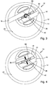
Figur 3 eine Draufsicht auf die Verdrängerpumpe mit kraftschlüssiger radialer aber deaktivierter Arretierung; -
Figur 4 eine Draufsicht auf die Verdrängerpumpe mit kraftschlüssiger radialer aktivierter Arretierung; -
Figur 5 eine perspektivische Ansicht der Verdrängerpumpe nachFigur 4 mit mechanischer Ansteuerung; -
Figur 6 eine konkretere Ausgestaltung der Pumpe nachFigur 5 ; -
Figur 7 einen Längsschnitt durch dieFigur 6 bei deaktivierter Arretierung; -
Figur 8 einen Längsschnitt durch dieFigur 6 bei aktivierter Arretierung; -
Fig. 9a ) das Spreizelement und das Blockierelement ausFig. 7 und8 in perspektivischer Darstellung; -
Fig. 9b ) das Spreizelement und das Blockierelement ausFig. 9a ) im Längsschnitt; -
Figur 10 eine perspektivische Ansicht der Verdrängerpumpe mit kraftschlüssiger axialer aber deaktivierter Arretierung; -
Figur 11 eine perspektivische Ansicht der Verdrängerpumpe nachFig. 10 mit aktivierter Arretierung; -
Figur 12 einen Längsschnitt durch eine konkretere Ausgestaltung der Pumpe nachFigur 11 ; -
Figur 13 einen perspektivischen Ausschnitt ausFig. 12 ; -
Figur 14 ein Schaltbild für eine elektromagnetische Ansteuerung der Arretierung bei Anwendung an einer Ölpumpe bzw. Nockenwelle; -
Figur 15 ein Schaltbild für eine interne pneumatische Ansteuerung der Arretierung über Unterdruck bei Anwendung an einer Ölpumpe bzw. Nockenwelle; -
Figur 16 ein Schaltbild für eine externe pneumatische Ansteuerung der Arretierung über ein Magnetventil bei Anwendung an einer Ölpumpe bzw. Nockenwelle; und -
Figur 17 ein Schaltbild für eine externe hydraulische oder pneumatische Ansteuerung der Arretierung bei Anwendung an einer Ölpumpe bzw. Nockenwelle. - In der
Figur 1 ist mit dem Bezugszeichen 10 schematisch eine als Flügelzellenpumpe ausgebildete Verdrängerpumpe bezeichnet, die ein Gehäuse 12 aufweist, in welchem ein Rotor 14 drehbar gelagert ist. Im Rotor 14 sind zwei Flügel 16 verschieblich geführt, so dass deren Flügelspitzen 18 eine Innenumfangswand 20 des Gehäuses 12 berühren. Der Innenraum 34 des Gehäuses 12 wird von den Flügeln 16 in Kammern 22, 24 und 26 unterteilt, wobei im gezeigten Fall die Kammer 22 eine Druckkammer und die Kammer 26 eine Saugkammer darstellen. Während der Drehung des Rotors 14 führen die Flügel 16 innerhalb des Rotors 14, d.h. in Flügelschächten 28, translatorische Bewegungen aus, die mit den Pfeilen 30 angedeutet sind. - Die
Figur 2 zeigt die Verdrängerpumpe 10 gemäßFigur 1 , wobei die Flügel 16 vollständig in den Rotor 14 eingefahren sind und die Flügelspitzen 18 sich auf dem oder innerhalb des Umkreises 32 des Rotors 14 befinden. Der Innenraum 34 wird von den Flügeln nicht mehr in Kammern unterteilt. Die Position der Flügel 16 wird von einer inFigur 2 nicht dargestellten Arretierung gehalten. - Wie aus der
Figur 1 und 2 , und auch aus den weiteren Figuren, hervorgeht, sind die Flügel 16 im Rotor parallel zueinander verlaufend angeordnet. Die Flügel 16 weisen dabei jeweils einen ersten, insbesondere bei eingefahrenen Flügeln 16 im Rotor 14 verbleibenden Abschnitt 80 auf, wobei sich, die Abschnitte 80, wie ausFigur 2 deutlich wird, senkrecht zur Verschiebeebene der Flügel 16 wenigstens abschnittsweise überlappen. Zwischen den beiden Flügeln 16, bzw. deren Abschnitte 80, befindet sich ein Zwischenraum 82, in dem vorteilhafterweise die Arretierung 36 untergebracht sein kann (Ausführungsformen gemäßFiguren 3 bis 9 ). - In den
Figuren 3 bis 8 weist die Verdrängerpumpe 10 eine im Zwischenraum 82 vorgesehene Arretierung 36 auf, die radial auf die Flügel 16 wirkt und kraftschlüssig arbeitet. Die Arretierung 36 sorgt dafür, dass die Flügel 16 bei nicht gebrauchter Verdrängerpumpe 10 im Rotor 14 bleiben, was inFigur 4 und5 dargestellt ist. Der Halt der Flügel 16 in der Nichtgebrauchslage erfolgt z.B. dadurch, dass die Flügel 16 mechanisch radial so durch Kraft- bzw. Reibschluss verklemmt (Pfeile 38) werden, dass sie nicht mehr nach außen gegen die Innenumfangswand 20 getrieben werden. - Die Arretierung 36 umfasst dabei ein im Zwischenraum 82 angeordnetes Blockierelement 84, das insbesondere aus elastisch nachgiebigem Kunststoff gebildet sein kann. Bei der Ausführungsform gemäß
Figur 3, 4 und5 weist das Blockierelement an seiner in denFiguren 3, 4 und5 gezeigten Oberseite eine sich in Längsrichtung des Blockierelements 84 erstreckende Ausnehmung 86 auf, die als Keilnut ausgebildet ist. - In diese Keilnut greift ein entlang seiner Längsachse bzw. den Pfeilen 42 verlagerbares Stellglied 40 ein. Das Stellglied 40 weist bei der Ausführungsform gemäß
Figur 3 bis 5 eine dem Blockierelement 86 zugewandte Konusspitze 88 auf, die in die Ausnehmung 86 derart eingreift, dass bei axialer Verlagerung des Stellglieds 40 in den Zwischenraum 82 hinein das Blockierelement 86 nach radial außen gespreizt wird und dadurch die Flügel 16 im Bereich ihrer Abschnitte 80 im Rotor kraftschlüssig festgesetzt werden. - In den
Figuren 6 bis 9 ist eine Weiterentwicklung der Ausführungsform gemäß derFiguren 3 bis 5 dargestellt, wobei entsprechende Bauteile mit entsprechenden Bezugszeichen versehen sind. - Im Zwischenraum 82 ist auch hier ein Blockierelement 84 vorhanden, das in
Figur 9a) und Figur 9b ) deutlich zu erkennen ist. Die Ausführungsform gemäß denFiguren 6 bis 9 weist neben dem über einen Antrieb 90 in axialer Richtung verlagerbaren Stellglied 40 ein mit dem Stellglied 40 in axialer Richtung bewegungsgekoppeltes Spreizelement 92 auf, das insbesondere inFigur 8 und 9 gut zu erkennen ist. Das Spreizelement 92 ist in axialer Richtung mit dem Stellglied 40 bewegungsgekoppelt; das Spreizelement 92 ist allerdings rotatorisch vom Stellglied 40entkoppelt. - In der
Figur 7 ist das Stellglied 40 in seiner zurückgefahrenen Position gezeigt; die Arretierung 36 ist folglich deaktiviert. In derFigur 8 ist der Antrieb 90 betätigt; das Stellglied ist folglich axial herausgefahren. Die Arretierung 36 ist folglich aktiviert. - Das dem Blockierelement 84 zugewandte freie Ende 94 des Spreizelements ist, wie aus
Figur 9b ) deutlich wird, konusförmig ausgebildet. Das freie Ende 94 greift, wie ebenfalls ausFigur 9a) und Figur 9b ) deutlich wird, in eine ebenfalls konusartig ausgebildete Ausnehmung 86 des Blockierelements 84. Dadurch wird das Blockierelement 84 beim axialen Einfahren des Spreizelements 92, bzw. dessen Ende 94, in radialer Richtung aufgespreizt. Dadurch werden, wie inFigur 8 dargestellt, die Flügel 16 in ihrer Lage reib- bzw. kraftschlüssig festgesetzt. - Das Spreizelement weist einen ersten, hülsenartigen Abschnitt auf, der das Stellelement 40 aufnimmt. Auf der dem Blockierelement 84 zugewandten Seite weist das Spreizelement 92 einen Stiftabschnitt mit dem freien Ende 94 auf. Im radial inneren Bereich des Hülsenabschnitts ist ein Ringelement 96 angeordnet; im Bodenbereich des Hülsenabschnitts eine Kugel 102.
- Zur axialen Bewegungskopplung des Stellglieds 40 mit dem Spreizelement 92 ist das Ringelement 96 zwischen dem Stellglied 40 und dem Spreizelement 92 vorgesehen, wobei das Ringelement 96 das abschnittsweise in einer spreizelementseitigen Ringnut 98 und abschnittsweise in einer stellelementseitigen Ringnut 100 mit vorzugsweise recht großem Spiel untergebracht ist. Dadurch wird erreicht, dass insbesondere beim Rückfahren des Stellelements 40 in die in
Figur 7 gezeigte Position das Spreizelement 42 mitgenommen wird. - Ferner ist in axialer Richtung zwischen dem Stellelement 40 und dem Spreizelement 92 zur rotatorischen Entkopplung die Kugel 102 vorgesehen. Dadurch wird erreicht, dass insbesondere bei der in
Figur 8 eingefahrenen Lage des Stellelements, in der sich das Spreizelement 92 mit dem Rotor mitdreht, eine Drehbewegung des Spreizelements 92 gegenüber dem Stellglied 40 möglich ist. Die Anordnung ist dabei derart, dass in der aktivierten Lage der Arretierung 36 vorzugsweise kein Berührkontakt zwischen dem Stellglied 40 und dem Spreizelement 92 im Bereich des Ringelements 96 vorliegt, so dass das Spreizelement möglichst kontaktfrei im Bereich des Ringelements 96 gegenüber dem Stellelement 40 drehen kann. - Die Funktionsweise der Ausführungsform gemäß
Figuren 6 bis 9 ist also wie folgt: - Ausgehend von der
Figur 7 wird der Antrieb 90 angesteuert. Beim Antrieb 90 kann es sich um einen pneumatischen Antrieb oder um einen magnetischen Antrieb handeln, der bewirkt, dass das Stellelement 40 in axialer Richtung ausgefahren wird. In derFigur 7 ist das Stellglied 40 eingefahren, wodurch das am Stellglied 40 angeordnete Spreizelement 92 keinen Berührkontakt mit dem Rotor 14 bzw. des im Rotor 14 zwischen den Flügeln 16 angeordneten Blockierelement 84 hat. Wird nun das Stellelement 40 in die inFigur 8 gezeigte Lage axial verschoben, so kommt es zum Eintauchen des freien Endes 94 des Spreizelements 92 in die Ausnehmung 86 des Blockierelements 84. Aufgrund des Berührkontakts zwischen dem Spreizelement 94 und dem Blockierelement 84 beginnt das Spreizelement 92 mit dem Rotor 16 zu rotieren. Über die Kugel 102 wird eine Rotation des Spreizelements 92 ermöglicht, wobei zugleich vom Stellelement 40 in axialer Richtung Kräfte in das Blockierelement 84 übertragen werden. Aufgrund eines weiteren Eintauchens des freien Endes 94 des Spreizelements 92 in die Ausnehmung 86 wird das Blockierelement 84 in radialer Richtung gespreizt. Die axialer kraft wir eine radial wirkende kraft umgeleitet. Je nach Schräge der Konusse kann dabei eine Kraftverstärkung in radialer Richtung erreicht werden. - Durch die radiale Kraft entsteht eine Reibkraft, die die Bewegung der Flügel hemmt. Da der Rotor weiter rotiert, werden die Flügel, dadurch, dass ihre freien Enden an der Rotorwand gleiten, automatisch in den Rotor eingeschoben. Aufgrund des Reibschlusses bzw. Kraftschlusses des Blockierelements wird erreicht, dass die Flügel im Rotor verbleiben. Die Arretierung ist damit aktiviert; die Pumpe 10 ist folglich deaktiviert und erbringt bei drehendem Rotor 14 keine Leistung.
- Soll die Pumpe 10 wieder in Betrieb genommen werden, so wird das Stellglied 40 in axialer Richtung in die in
Figur 7 gezeigte Position rückgefahren. Das Spreizelement 92 wird aufgrund der translatorischen Bewegungskopplung durch das Ringelement 96 in axialer Richtung mit rückgefahren. Das freie Ende 94 rückt dabei aus der Ausnehmung 86 des Blockierelements heraus. Das Spreizelement 92 wird folglich dann nicht mehr rotatorisch vom Blockierelement 84 angetrieben; es dreht dann nicht mehr mit. - Aufgrund der elastischen Nachgiebigkeit des Blockierelements 84 wird der Reib- bzw. Kraftschluss in radialer Richtung mit den Flügeln 16 gelöst. Die Flügel 16 können sich dann wieder frei im Rotor 14 bewegen. Die Pumpe beginnt wieder Leistung zu erbringen.
- Bei den Ausführungsformen gemäß den
Figuren 1 bis 13 weist die Verdrängerpumpe 10 eine Arretierung 36 auf, die axial auf die Flügel 16 wirkt und kraft- bzw. reibschlüssig arbeitet. Die Arretierung 36 sorgt dafür, dass die Flügel 16 bei nicht gebrauchter Verdrängerpumpe 10 im Rotor 14 bleiben, was inFigur 11 dargestellt ist. Der Halt der Flügel 16 erfolgt z.B. dadurch, dass die Flügel 16 mechanisch axial so stark verklemmt werden, dass sie nicht mehr nach außen gegen die Innenumfangswand 20 getrieben werden. Die Steuerung erfolgt über eine mechanische Kraft, die in Richtung der Pfeile 46 auf die Stirnflächen der Flügel 16 wirkt, sodass die Flügel 16 im Rotor 16 arretiert werden. -
Figur 12 und 13 zeigen eine derartige Konkretisierung, wobei Bauelemente, die in den vorhergehenden Figuren bereits gezeigt sind mit entsprechenden Bezugszeichen gekennzeichnet sind. - In den
Figuren 12 und 13 ist das Blockierelement 84, das tellerartig ausgebildet ist, deutlich zu erkennen. Das Blockierelement 84 weist einen ersten hülsenartigen Abschnitt zur Aufnahme des freien Endes des Stellelements 40 auf. Auf der den Flügeln 16 zugewandten Seite ist das Blockierelement tellerartig ausgebildet, so dass es in geeigneter Weise gegen gegen die beiden nebeneinander angeordneten, in einer Ebene liegenden Stirnseiten 104 der Flügel 16 wirken kann. Die Flügel 16 werden folglich reib- bzw. kraftschlüssig in dem Rotor 16 bei aktivierter Verrieglung gehalten. - Das Blockierelement 84 wird in axialer Richtung über das Stellelement 40 des Antriebs 90 betätigt. Das Stellelement 40 ist dabei in axialer Richtung mit dem Blockierelement 84 bewegungsgekoppelt und rotatorisch entkoppelt (über das Ringelement 96 und die Kugel 102, wie zu den
Figuren 6 bis 10 bezüglich des Stellelements 40 und dem Spreizelement 92 beschrieben). - Wird folglich das Stellelement 40 aus seiner axialen eingefahrenen Lage durch Ansteuern des Antriebs 90 in die axial ausgefahrene Lage verlagert, wird das Blockierelement in axialer Richtung gegen die Stirnseiten 104 der Flügel 16 beaufschlagt. Die Flügel 16 können damit im Rotor festgesetzt werden.
- Das das Blockierelement 84 im Rotor 16 untergebracht ist, dreht es mit dem Rotor 16 mit. Über die Kugel 102 kann eine Drehentkopplung bereitgestellt werden, so dass trotz Drehung des Blockierelements 84 und Nichtdrehung des Stellglieds 40 in axialer Richtung Kräfte übertragen werden können.
- Zur Deaktivierung der Arretierung 36 wird das Stellglied in axialer Richtung eingefahren. Das Blockierelement 84 wird über das Ringelement 96 in axialer Richtung vom Stellglied 40 mitgenommen. Das Blockierelement hebt dann von den Stirnseiten 104 der Flügel 16 ab. Die Flügel 16 können sich dann wieder frei im Rotor 14 bewegen. Die Pumpe 10 ist folglich wieder aktiviert.
- Die
Figuren 14a und 14b zeigen ein Schaltbild für eine elektromagnetische Ansteuerung der Arretierung 36. Über eine Antriebswelle 50 (Nockenwelle 62 eines Motors 64) wird eine Schmiermittelpumpe 52 angetrieben, die wiederum die Verdrängerpumpe 10 antreibt und einen Bremskraftverstärker 54 mit Unterdruck versorgt. Der Druck im Bremskraftverstärker 54 wird mit einem Sensor 56 erfasst und an eine Steuerelektronik 58 weitergeleitet, die ihrerseits einen Elektromagneten 60 ansteuert. Dieser treibt die Arretierung 36 an, die auf die Flügel 16 in der Verdrängerpumpe 10 einwirkt. Sobald ein vorgegebener Unterdruck im Bremskraftverstärker 54 erreicht ist, wird die Arretierung 36 aktiviert und die Flügel 16 im Rotor 14 blockiert. Ein Abbau des Unterdrucks im Bremskraftverstärker 54 wird durch ein Rückschlagventil 66 verhindert. - Die
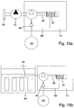
Figuren 15a und 15b zeigen ein Schaltbild für eine interne pneumatische Ansteuerung der Arretierung 36. Der Druck im Bremskraftverstärker 54 wird direkt über eine Leitung 68 an eine interne pneumatische Unterdrucksteuerung 70 weitergegeben, die ihrerseits die Arretierung 36 antreibt, die wiederum auf die Flügel 16 in der Verdrängerpumpe 10 einwirkt. Mit dem Bezugszeichen 10 ist die Gesamtheit der Verdrängerpumpe angedeutet. - Die
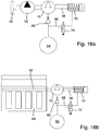
Figuren 16a und 16b zeigen ein Schaltbild für eine externe pneumatische Ansteuerung der Arretierung 36. Der Druck im Bremskraftverstärker 54 wird über die Leitung 68 an ein externes Magnetventil 72 weitergegeben, welches die pneumatische Unterdrucksteuerung 70 ansteuert, welches seinerseits die Arretierung 36 antreibt, die wiederum auf die Flügel 16 in der Verdrängerpumpe 10 einwirkt. - Die
Figuren 17a und 17b zeigen ein Schaltbild für eine externe hydraulische oder pneumatische Ansteuerung der Arretierung 36, ähnlich der Ansteuerung gemäß der Figuren 10a und 10b. Der Druck im Bremskraftverstärker 54 wird mit dem Sensor 56 erfasst und an die Steuerelektronik 58 weitergeleitet, die ihrerseits die hydraulische oder pneumatische Unterdrucksteuerung 70 ansteuert, was mit Pfeilen 74 und 76 angedeutet ist. Sobald ein vorgegebener Unterdruck im Bremskraftverstärker 54 erreicht ist, wird die Arretierung 36 aktiviert und die Flügel 16 im Rotor 14 blockiert.
Claims (9)
- Verdrängerpumpe (10) mit einem topfförmigen Gehäuse (12), einem im Gehäuse (12) drehbar gelagerten Rotor (14) und wenigstens einem im Rotor (14) verschieblich geführten Flügel (16), dessen Flügelspitze (18) im Betrieb der Verdrängerpumpe (10) an der Innenumfangswand (20) des Gehäuses (12) anliegt und den Innenraum (34) in Kammern (22, 24, 26) unterteilt, wobei eine die Verschiebung des Flügels (16) im Rotor (14) hemmende, kraft- oder reibschlüssig am Flügel (16) angreifende Arretierung (36) vorgesehen ist, dadurch gekennzeichnet, dass ein gehäuseseitiges, über einen Antrieb (90) in axialer Richtung betätigbares Stellglied (40) vorgesehen ist, das die Arretierung (36) betätigt, wobei zwischen dem Stellglied (40) und der Arretierung (36) eine Drehentkopplung sowie eine axiale Bewegungskopplung vorgesehen sind.
- Verdrängerpumpe (10) nach Anspruch 1, dadurch gekennzeichnet, dass im Rotor (14) wenigstens zwei parallel zueinander verlaufend angeordnete Flügel vorgesehen sind, wobei die Flügel (16) jeweils einen ersten, im Rotor verbleibenden Abschnitt (80) derart aufweisen, dass die jeweils ersten Abschnitte (80) sich senkrecht zur Verschiebeebene der Flügel (16) wenigstens abschnittsweise überlappen, und wobei die Arretierung (36) an den ersten Abschnitten (80) der Flügel (16) angreift.
- Verdrängerpumpe (10) nach Anspruch 2, dadurch gekennzeichnet, dass die Arretierung (36) in radialer und/oder axialer Richtung am jeweils ersten Abschnitt (80) des Flügels (16) angreift.
- Verdrängerpumpe (10) nach Anspruch 2 oder 3, dadurch gekennzeichnet, dass die Arretierung (36) in einem zwischen den ersten Abschnitten (80) der Flügel vorgesehenen Zwischenraum (82) angeordnet ist und in radialer Richtung gegen die einander zugewanden Breitseiten der ersten Abschnitte (80) der Flügel (16) wirkt.
- Verdrängerpumpe (10) nach Anspruch 4, dadurch gekennzeichnet, dass die Arretierung (36) ein im Zwischenraum (82) angeordnetes, elastisch nachgiebiges Blockierelement (84) mit einer Ausnehmung (86) und ein in die Ausnehmung (86) eingreifendes Spreizelement (92) derart aufweist ist, dass das Spreizelement (92) bei axialer Verlagerung das Blockierelement (84) so aufspreitzt, dass das Blockierelement (84) gegen die einander zugewanden Breitseiten der ersten Abschnitte (86) der Flügel (16) wirkt.
- Verdrängerpumpe (10) nach Anspruch 2 oder 3, dadurch gekennzeichnet, dass die Arretierung (36) ein in axialer Verlängerung der Flügel (16) angeordnetes, in axialer Richtung verlagerbares Blockierelement (84) derart aufweist, dass es bei axialer Verlagerung gegen die parallel zueinander oder in einer Ebene liegenden Stirnseiten (104) der Flügel (16) wirkt.
- Verdrängerpumpe (10) nach einem der vorhergehenden Ansprüche, dadurch gekennzeichnet, dass die Drehentkopplung von einer Kugel (102) gebildet wird.
- Verdrängerpumpe (10) nach Anspruch 5 oder 6 oder 5 und 7 oder 6 und 7, dadurch gekennzeichnet, dass die axiale Bewegungskopplung von einem am Stellglied (40) vorgesehenen Ringelement (96) und einer am Spreizelement (92) oder am Blockierelement (84) vorgesehenen, das Ringelement wenigstens abschnittsweise aufnehmenden Ringnut (90) gebildet wird.
- Verdrängerpumpe (10) nach einem der vorhergehenden Ansprüche, dadurch gekennzeichnet, dass die Arretierung (36) dann aktiviert wird, wenn der Flügel (16) seine maximal in den Rotor (14) eingefahrene Stellung einnimmt und/oder dass die Arretierung (36) dann deaktiviert wird, wenn der Rotor (14) eine Drehlage einnimmt, in welcher die Flügelspitze (18) des arretierten Flügels (16) seine geringste Entfernung zur Innenumfangswand (20) aufweist.
Applications Claiming Priority (2)
| Application Number | Priority Date | Filing Date | Title |
|---|---|---|---|
| DE102012210048A DE102012210048A1 (de) | 2012-06-14 | 2012-06-14 | Verdrängerpumpe |
| PCT/EP2013/062278 WO2013186314A1 (de) | 2012-06-14 | 2013-06-13 | Verdrängerpumpe |
Publications (2)
| Publication Number | Publication Date |
|---|---|
| EP2825775A1 EP2825775A1 (de) | 2015-01-21 |
| EP2825775B1 true EP2825775B1 (de) | 2016-02-24 |
Family
ID=48613628
Family Applications (1)
| Application Number | Title | Priority Date | Filing Date |
|---|---|---|---|
| EP13728397.4A Active EP2825775B1 (de) | 2012-06-14 | 2013-06-13 | Verdrängerpumpe |
Country Status (5)
| Country | Link |
|---|---|
| US (1) | US9651042B2 (de) |
| EP (1) | EP2825775B1 (de) |
| CN (1) | CN104471249B (de) |
| DE (2) | DE102012210048A1 (de) |
| WO (1) | WO2013186314A1 (de) |
Families Citing this family (6)
| Publication number | Priority date | Publication date | Assignee | Title |
|---|---|---|---|---|
| DE102013222597B4 (de) * | 2013-11-07 | 2016-03-24 | Joma-Polytec Gmbh | Verdrängerpumpe |
| DE102015213099B3 (de) | 2015-07-13 | 2016-08-04 | Joma-Polytec Gmbh | Kunststoffrotor für Vakuumpumpe |
| CN108474379B (zh) * | 2016-03-10 | 2020-10-30 | 威伯科欧洲有限责任公司 | 双叶片旋转真空泵 |
| CN107288870B (zh) * | 2017-08-28 | 2019-01-22 | 大连海密梯克泵业有限公司 | 液压动力装置及其泵 |
| CN107327401B (zh) * | 2017-08-28 | 2019-07-12 | 北京华德力士乐液压气动设备有限公司 | 泵及使用该泵的液压动力总成 |
| WO2024010884A2 (en) * | 2022-07-08 | 2024-01-11 | Torad Engineering, Llc | Valve for rotary fluid displacement assembly and rotary fluid displacement assembly comprising same |
Family Cites Families (9)
| Publication number | Priority date | Publication date | Assignee | Title |
|---|---|---|---|---|
| SE355845B (de) | 1968-11-06 | 1973-05-07 | Wittig K Gmbh Maschf | |
| DE2502184A1 (de) * | 1975-01-21 | 1976-07-22 | Bosch Gmbh Robert | Verfahren und vorrichtung zum steuern einer kaelteanlage in einem kraftfahrzeug |
| DE3015409A1 (de) * | 1980-04-22 | 1981-10-29 | Robert Bosch Gmbh, 7000 Stuttgart | Rotierende vakuumpumpe |
| IT1190114B (it) | 1985-06-15 | 1988-02-10 | Barmag Barmer Maschf | Pompa ad alette e celle,con alette a forma di gancio |
| DE3618303A1 (de) * | 1985-06-15 | 1986-12-18 | Barmag Barmer Maschinenfabrik Ag, 5630 Remscheid | Fluegelzellenpumpe mit hakenfoermigen fluegeln |
| DE8517622U1 (de) * | 1985-06-15 | 1986-10-16 | Barmag Barmer Maschinenfabrik Ag, 5630 Remscheid | Flügelzellenpumpe mit hakenförmigen Flügeln |
| CN1009024B (zh) * | 1986-09-24 | 1990-08-01 | 郑悦 | 轴向变量泵或马达 |
| EP1327778A3 (de) * | 2000-03-15 | 2003-07-23 | Joma-Hydromechanic GmbH | Flügelzellenpumpe |
| AU2003903625A0 (en) * | 2003-07-15 | 2003-07-31 | Norman Ian Mathers | A hydraulic machine |
-
2012
- 2012-06-14 DE DE102012210048A patent/DE102012210048A1/de not_active Ceased
-
2013
- 2013-06-13 EP EP13728397.4A patent/EP2825775B1/de active Active
- 2013-06-13 US US14/406,548 patent/US9651042B2/en active Active
- 2013-06-13 CN CN201380031598.4A patent/CN104471249B/zh active Active
- 2013-06-13 DE DE202013012179.3U patent/DE202013012179U1/de not_active Expired - Lifetime
- 2013-06-13 WO PCT/EP2013/062278 patent/WO2013186314A1/de not_active Ceased
Also Published As
| Publication number | Publication date |
|---|---|
| EP2825775A1 (de) | 2015-01-21 |
| CN104471249A (zh) | 2015-03-25 |
| US9651042B2 (en) | 2017-05-16 |
| DE202013012179U1 (de) | 2015-07-14 |
| WO2013186314A1 (de) | 2013-12-19 |
| DE102012210048A1 (de) | 2013-12-19 |
| US20150132169A1 (en) | 2015-05-14 |
| CN104471249B (zh) | 2016-09-28 |
Similar Documents
| Publication | Publication Date | Title |
|---|---|---|
| EP0335083B1 (de) | Vorrichtung zur relativen Winkelverstellung zwischen zwei in Antriebsverbindung stehenden Wellen | |
| EP1302630B1 (de) | Vorrichtung zum Verändern der Steuerzeiten von Gaswechselventilen einer Brennkraftmaschine, insbesondere Rotationskolben-Verstelleinrichtung zur Drehwinkelverstellung einer Nockenwelle gegenüber einer Kurbelwelle | |
| WO2013186314A1 (de) | Verdrängerpumpe | |
| DE102008020892A1 (de) | Stellvorrichtung | |
| EP2754911A1 (de) | Hydraulische Betätigungsvorrichtung für die Betätigung wenigstens einer Reibkupplung und wenigstens eines Getriebestellglieds in einem Kraftfahrzeug | |
| EP2742264B1 (de) | Schieberventil mit einem ventilschieber | |
| WO2007039103A1 (de) | Brennkraftmaschine mit variablem verdichtungsverhältnis | |
| DE102006051809A1 (de) | Stellvorrichtung | |
| EP2313656A2 (de) | Pumpeneinheit | |
| WO2004111396A1 (de) | Nockenwellensteller für eine brennkraftmaschine | |
| EP1749146B1 (de) | Nockenwellenversteller | |
| DE102004033894A1 (de) | Nockenwellenverstelleinrichtung | |
| WO2015090416A1 (de) | Kfz-vakuumpumpe mit schaltbarer kupplung | |
| DE102014222589B4 (de) | Nockenwellenversteller mit modifizierter Abdichtung | |
| EP0976948B1 (de) | Dämpfungseinrichtung für bewegte Massen, vorzugsweise für elektromagnetische Antriebssysteme | |
| DE102008043673A1 (de) | Verstellsystem für Nockenwellen einer Brennkraftmaschine | |
| EP2035265B1 (de) | Fahrzeugbremsanlagen-kolbenpumpe | |
| DE10036546B4 (de) | Vorrichtung zum Verändern der Steuerzeiten von Gaswechselventilen einer Brennkraftmaschine, insbesondere hydraulische Nockenwellen-Verstelleinrichtungen in Rotationskolbenbauart | |
| DE102013216410A1 (de) | Arretierungsvorrichtung | |
| WO2018069128A1 (de) | Hydromechanischer arretierungszylinder und hydraulisches steuersystem zu dessen betätigung | |
| DE102009019397B4 (de) | Phasenversteller für Verbrennungsmotoren mit einem Verriegelungselement | |
| DE102014222590B4 (de) | Nockenwellenversteller mit Steuerhülse | |
| DE102009057330A1 (de) | Elektromechanische Bremse für ein Kraftfahrzeug | |
| DE102013114303A1 (de) | Kompressorsystem mit einer Kolbenhubeinstellvorrichtung | |
| EP2640997B1 (de) | Schaltbare kupplung, insbesondere für nebenaggregate im pkw |
Legal Events
| Date | Code | Title | Description |
|---|---|---|---|
| PUAI | Public reference made under article 153(3) epc to a published international application that has entered the european phase |
Free format text: ORIGINAL CODE: 0009012 |
|
| 17P | Request for examination filed |
Effective date: 20140820 |
|
| AK | Designated contracting states |
Kind code of ref document: A1 Designated state(s): AL AT BE BG CH CY CZ DE DK EE ES FI FR GB GR HR HU IE IS IT LI LT LU LV MC MK MT NL NO PL PT RO RS SE SI SK SM TR |
|
| AX | Request for extension of the european patent |
Extension state: BA ME |
|
| GRAP | Despatch of communication of intention to grant a patent |
Free format text: ORIGINAL CODE: EPIDOSNIGR1 |
|
| RIN1 | Information on inventor provided before grant (corrected) |
Inventor name: BLANK, ANDREAS Inventor name: THOMA, MARTIN Inventor name: SCHNEIDER, WILLI Inventor name: HELLE, TORSTEN Inventor name: KAWA, BENJAMIN Inventor name: HESS, BERND Inventor name: OTT, HANS-PETER |
|
| DAX | Request for extension of the european patent (deleted) | ||
| INTG | Intention to grant announced |
Effective date: 20150810 |
|
| GRAS | Grant fee paid |
Free format text: ORIGINAL CODE: EPIDOSNIGR3 |
|
| INTG | Intention to grant announced |
Effective date: 20151211 |
|
| GRAA | (expected) grant |
Free format text: ORIGINAL CODE: 0009210 |
|
| AK | Designated contracting states |
Kind code of ref document: B1 Designated state(s): AL AT BE BG CH CY CZ DE DK EE ES FI FR GB GR HR HU IE IS IT LI LT LU LV MC MK MT NL NO PL PT RO RS SE SI SK SM TR |
|
| REG | Reference to a national code |
Ref country code: GB Ref legal event code: FG4D Free format text: NOT ENGLISH |
|
| REG | Reference to a national code |
Ref country code: CH Ref legal event code: EP |
|
| REG | Reference to a national code |
Ref country code: AT Ref legal event code: REF Ref document number: 776887 Country of ref document: AT Kind code of ref document: T Effective date: 20160315 |
|
| REG | Reference to a national code |
Ref country code: IE Ref legal event code: FG4D Free format text: LANGUAGE OF EP DOCUMENT: GERMAN |
|
| REG | Reference to a national code |
Ref country code: DE Ref legal event code: R096 Ref document number: 502013002018 Country of ref document: DE |
|
| REG | Reference to a national code |
Ref country code: LT Ref legal event code: MG4D |
|
| REG | Reference to a national code |
Ref country code: NL Ref legal event code: MP Effective date: 20160224 |
|
| PG25 | Lapsed in a contracting state [announced via postgrant information from national office to epo] |
Ref country code: FI Free format text: LAPSE BECAUSE OF FAILURE TO SUBMIT A TRANSLATION OF THE DESCRIPTION OR TO PAY THE FEE WITHIN THE PRESCRIBED TIME-LIMIT Effective date: 20160224 Ref country code: GR Free format text: LAPSE BECAUSE OF FAILURE TO SUBMIT A TRANSLATION OF THE DESCRIPTION OR TO PAY THE FEE WITHIN THE PRESCRIBED TIME-LIMIT Effective date: 20160525 Ref country code: IT Free format text: LAPSE BECAUSE OF FAILURE TO SUBMIT A TRANSLATION OF THE DESCRIPTION OR TO PAY THE FEE WITHIN THE PRESCRIBED TIME-LIMIT Effective date: 20160224 Ref country code: ES Free format text: LAPSE BECAUSE OF FAILURE TO SUBMIT A TRANSLATION OF THE DESCRIPTION OR TO PAY THE FEE WITHIN THE PRESCRIBED TIME-LIMIT Effective date: 20160224 Ref country code: NO Free format text: LAPSE BECAUSE OF FAILURE TO SUBMIT A TRANSLATION OF THE DESCRIPTION OR TO PAY THE FEE WITHIN THE PRESCRIBED TIME-LIMIT Effective date: 20160524 Ref country code: HR Free format text: LAPSE BECAUSE OF FAILURE TO SUBMIT A TRANSLATION OF THE DESCRIPTION OR TO PAY THE FEE WITHIN THE PRESCRIBED TIME-LIMIT Effective date: 20160224 |
|
| PG25 | Lapsed in a contracting state [announced via postgrant information from national office to epo] |
Ref country code: PT Free format text: LAPSE BECAUSE OF FAILURE TO SUBMIT A TRANSLATION OF THE DESCRIPTION OR TO PAY THE FEE WITHIN THE PRESCRIBED TIME-LIMIT Effective date: 20160624 Ref country code: RS Free format text: LAPSE BECAUSE OF FAILURE TO SUBMIT A TRANSLATION OF THE DESCRIPTION OR TO PAY THE FEE WITHIN THE PRESCRIBED TIME-LIMIT Effective date: 20160224 Ref country code: PL Free format text: LAPSE BECAUSE OF FAILURE TO SUBMIT A TRANSLATION OF THE DESCRIPTION OR TO PAY THE FEE WITHIN THE PRESCRIBED TIME-LIMIT Effective date: 20160224 Ref country code: LV Free format text: LAPSE BECAUSE OF FAILURE TO SUBMIT A TRANSLATION OF THE DESCRIPTION OR TO PAY THE FEE WITHIN THE PRESCRIBED TIME-LIMIT Effective date: 20160224 Ref country code: SE Free format text: LAPSE BECAUSE OF FAILURE TO SUBMIT A TRANSLATION OF THE DESCRIPTION OR TO PAY THE FEE WITHIN THE PRESCRIBED TIME-LIMIT Effective date: 20160224 Ref country code: NL Free format text: LAPSE BECAUSE OF FAILURE TO SUBMIT A TRANSLATION OF THE DESCRIPTION OR TO PAY THE FEE WITHIN THE PRESCRIBED TIME-LIMIT Effective date: 20160224 Ref country code: LT Free format text: LAPSE BECAUSE OF FAILURE TO SUBMIT A TRANSLATION OF THE DESCRIPTION OR TO PAY THE FEE WITHIN THE PRESCRIBED TIME-LIMIT Effective date: 20160224 |
|
| PG25 | Lapsed in a contracting state [announced via postgrant information from national office to epo] |
Ref country code: EE Free format text: LAPSE BECAUSE OF FAILURE TO SUBMIT A TRANSLATION OF THE DESCRIPTION OR TO PAY THE FEE WITHIN THE PRESCRIBED TIME-LIMIT Effective date: 20160224 Ref country code: DK Free format text: LAPSE BECAUSE OF FAILURE TO SUBMIT A TRANSLATION OF THE DESCRIPTION OR TO PAY THE FEE WITHIN THE PRESCRIBED TIME-LIMIT Effective date: 20160224 |
|
| REG | Reference to a national code |
Ref country code: DE Ref legal event code: R097 Ref document number: 502013002018 Country of ref document: DE |
|
| PG25 | Lapsed in a contracting state [announced via postgrant information from national office to epo] |
Ref country code: SK Free format text: LAPSE BECAUSE OF FAILURE TO SUBMIT A TRANSLATION OF THE DESCRIPTION OR TO PAY THE FEE WITHIN THE PRESCRIBED TIME-LIMIT Effective date: 20160224 Ref country code: SM Free format text: LAPSE BECAUSE OF FAILURE TO SUBMIT A TRANSLATION OF THE DESCRIPTION OR TO PAY THE FEE WITHIN THE PRESCRIBED TIME-LIMIT Effective date: 20160224 Ref country code: CZ Free format text: LAPSE BECAUSE OF FAILURE TO SUBMIT A TRANSLATION OF THE DESCRIPTION OR TO PAY THE FEE WITHIN THE PRESCRIBED TIME-LIMIT Effective date: 20160224 Ref country code: RO Free format text: LAPSE BECAUSE OF FAILURE TO SUBMIT A TRANSLATION OF THE DESCRIPTION OR TO PAY THE FEE WITHIN THE PRESCRIBED TIME-LIMIT Effective date: 20160224 |
|
| PG25 | Lapsed in a contracting state [announced via postgrant information from national office to epo] |
Ref country code: BE Free format text: LAPSE BECAUSE OF NON-PAYMENT OF DUE FEES Effective date: 20160630 |
|
| PLBE | No opposition filed within time limit |
Free format text: ORIGINAL CODE: 0009261 |
|
| STAA | Information on the status of an ep patent application or granted ep patent |
Free format text: STATUS: NO OPPOSITION FILED WITHIN TIME LIMIT |
|
| PG25 | Lapsed in a contracting state [announced via postgrant information from national office to epo] |
Ref country code: MC Free format text: LAPSE BECAUSE OF FAILURE TO SUBMIT A TRANSLATION OF THE DESCRIPTION OR TO PAY THE FEE WITHIN THE PRESCRIBED TIME-LIMIT Effective date: 20160224 |
|
| REG | Reference to a national code |
Ref country code: CH Ref legal event code: PL |
|
| 26N | No opposition filed |
Effective date: 20161125 |
|
| PG25 | Lapsed in a contracting state [announced via postgrant information from national office to epo] |
Ref country code: BG Free format text: LAPSE BECAUSE OF FAILURE TO SUBMIT A TRANSLATION OF THE DESCRIPTION OR TO PAY THE FEE WITHIN THE PRESCRIBED TIME-LIMIT Effective date: 20160524 Ref country code: SI Free format text: LAPSE BECAUSE OF FAILURE TO SUBMIT A TRANSLATION OF THE DESCRIPTION OR TO PAY THE FEE WITHIN THE PRESCRIBED TIME-LIMIT Effective date: 20160224 |
|
| REG | Reference to a national code |
Ref country code: IE Ref legal event code: MM4A |
|
| REG | Reference to a national code |
Ref country code: FR Ref legal event code: ST Effective date: 20170228 |
|
| PG25 | Lapsed in a contracting state [announced via postgrant information from national office to epo] |
Ref country code: FR Free format text: LAPSE BECAUSE OF NON-PAYMENT OF DUE FEES Effective date: 20160630 Ref country code: CH Free format text: LAPSE BECAUSE OF NON-PAYMENT OF DUE FEES Effective date: 20160630 Ref country code: LI Free format text: LAPSE BECAUSE OF NON-PAYMENT OF DUE FEES Effective date: 20160630 |
|
| PG25 | Lapsed in a contracting state [announced via postgrant information from national office to epo] |
Ref country code: IE Free format text: LAPSE BECAUSE OF NON-PAYMENT OF DUE FEES Effective date: 20160613 |
|
| GBPC | Gb: european patent ceased through non-payment of renewal fee |
Effective date: 20170613 |
|
| PG25 | Lapsed in a contracting state [announced via postgrant information from national office to epo] |
Ref country code: GB Free format text: LAPSE BECAUSE OF NON-PAYMENT OF DUE FEES Effective date: 20170613 |
|
| PG25 | Lapsed in a contracting state [announced via postgrant information from national office to epo] |
Ref country code: HU Free format text: LAPSE BECAUSE OF FAILURE TO SUBMIT A TRANSLATION OF THE DESCRIPTION OR TO PAY THE FEE WITHIN THE PRESCRIBED TIME-LIMIT; INVALID AB INITIO Effective date: 20130613 |
|
| PG25 | Lapsed in a contracting state [announced via postgrant information from national office to epo] |
Ref country code: IS Free format text: LAPSE BECAUSE OF FAILURE TO SUBMIT A TRANSLATION OF THE DESCRIPTION OR TO PAY THE FEE WITHIN THE PRESCRIBED TIME-LIMIT Effective date: 20160224 Ref country code: MK Free format text: LAPSE BECAUSE OF FAILURE TO SUBMIT A TRANSLATION OF THE DESCRIPTION OR TO PAY THE FEE WITHIN THE PRESCRIBED TIME-LIMIT Effective date: 20160224 Ref country code: MT Free format text: LAPSE BECAUSE OF FAILURE TO SUBMIT A TRANSLATION OF THE DESCRIPTION OR TO PAY THE FEE WITHIN THE PRESCRIBED TIME-LIMIT Effective date: 20160224 Ref country code: LU Free format text: LAPSE BECAUSE OF NON-PAYMENT OF DUE FEES Effective date: 20160613 Ref country code: CY Free format text: LAPSE BECAUSE OF FAILURE TO SUBMIT A TRANSLATION OF THE DESCRIPTION OR TO PAY THE FEE WITHIN THE PRESCRIBED TIME-LIMIT Effective date: 20160224 |
|
| PG25 | Lapsed in a contracting state [announced via postgrant information from national office to epo] |
Ref country code: TR Free format text: LAPSE BECAUSE OF FAILURE TO SUBMIT A TRANSLATION OF THE DESCRIPTION OR TO PAY THE FEE WITHIN THE PRESCRIBED TIME-LIMIT Effective date: 20160224 Ref country code: AL Free format text: LAPSE BECAUSE OF FAILURE TO SUBMIT A TRANSLATION OF THE DESCRIPTION OR TO PAY THE FEE WITHIN THE PRESCRIBED TIME-LIMIT Effective date: 20160224 |
|
| REG | Reference to a national code |
Ref country code: AT Ref legal event code: MM01 Ref document number: 776887 Country of ref document: AT Kind code of ref document: T Effective date: 20180613 |
|
| PG25 | Lapsed in a contracting state [announced via postgrant information from national office to epo] |
Ref country code: AT Free format text: LAPSE BECAUSE OF NON-PAYMENT OF DUE FEES Effective date: 20180613 |
|
| P01 | Opt-out of the competence of the unified patent court (upc) registered |
Effective date: 20230620 |
|
| PGFP | Annual fee paid to national office [announced via postgrant information from national office to epo] |
Ref country code: DE Payment date: 20250815 Year of fee payment: 13 |