EP2825410B1 - Dispositif de montage d'un boîtier, notamment d'une radio, dans un compartiment de planche de bord d'un véhicule automobile - Google Patents
Dispositif de montage d'un boîtier, notamment d'une radio, dans un compartiment de planche de bord d'un véhicule automobile Download PDFInfo
- Publication number
- EP2825410B1 EP2825410B1 EP13701666.3A EP13701666A EP2825410B1 EP 2825410 B1 EP2825410 B1 EP 2825410B1 EP 13701666 A EP13701666 A EP 13701666A EP 2825410 B1 EP2825410 B1 EP 2825410B1
- Authority
- EP
- European Patent Office
- Prior art keywords
- unit
- stud
- slideway
- mounting
- facade
- Prior art date
- Legal status (The legal status is an assumption and is not a legal conclusion. Google has not performed a legal analysis and makes no representation as to the accuracy of the status listed.)
- Not-in-force
Links
Images


Classifications
-
- B—PERFORMING OPERATIONS; TRANSPORTING
- B60—VEHICLES IN GENERAL
- B60R—VEHICLES, VEHICLE FITTINGS, OR VEHICLE PARTS, NOT OTHERWISE PROVIDED FOR
- B60R11/00—Arrangements for holding or mounting articles, not otherwise provided for
- B60R11/02—Arrangements for holding or mounting articles, not otherwise provided for for radio sets, television sets, telephones, or the like; Arrangement of controls thereof
- B60R11/0205—Arrangements for holding or mounting articles, not otherwise provided for for radio sets, television sets, telephones, or the like; Arrangement of controls thereof for radio sets
-
- B—PERFORMING OPERATIONS; TRANSPORTING
- B60—VEHICLES IN GENERAL
- B60K—ARRANGEMENT OR MOUNTING OF PROPULSION UNITS OR OF TRANSMISSIONS IN VEHICLES; ARRANGEMENT OR MOUNTING OF PLURAL DIVERSE PRIME-MOVERS IN VEHICLES; AUXILIARY DRIVES FOR VEHICLES; INSTRUMENTATION OR DASHBOARDS FOR VEHICLES; ARRANGEMENTS IN CONNECTION WITH COOLING, AIR INTAKE, GAS EXHAUST OR FUEL SUPPLY OF PROPULSION UNITS IN VEHICLES
- B60K35/00—Instruments specially adapted for vehicles; Arrangement of instruments in or on vehicles
- B60K35/50—Instruments characterised by their means of attachment to or integration in the vehicle
-
- B—PERFORMING OPERATIONS; TRANSPORTING
- B60—VEHICLES IN GENERAL
- B60R—VEHICLES, VEHICLE FITTINGS, OR VEHICLE PARTS, NOT OTHERWISE PROVIDED FOR
- B60R11/00—Arrangements for holding or mounting articles, not otherwise provided for
- B60R11/02—Arrangements for holding or mounting articles, not otherwise provided for for radio sets, television sets, telephones, or the like; Arrangement of controls thereof
-
- B—PERFORMING OPERATIONS; TRANSPORTING
- B60—VEHICLES IN GENERAL
- B60R—VEHICLES, VEHICLE FITTINGS, OR VEHICLE PARTS, NOT OTHERWISE PROVIDED FOR
- B60R11/00—Arrangements for holding or mounting articles, not otherwise provided for
- B60R2011/0001—Arrangements for holding or mounting articles, not otherwise provided for characterised by position
- B60R2011/0003—Arrangements for holding or mounting articles, not otherwise provided for characterised by position inside the vehicle
- B60R2011/0005—Dashboard
-
- B—PERFORMING OPERATIONS; TRANSPORTING
- B60—VEHICLES IN GENERAL
- B60R—VEHICLES, VEHICLE FITTINGS, OR VEHICLE PARTS, NOT OTHERWISE PROVIDED FOR
- B60R11/00—Arrangements for holding or mounting articles, not otherwise provided for
- B60R2011/0042—Arrangements for holding or mounting articles, not otherwise provided for characterised by mounting means
-
- B—PERFORMING OPERATIONS; TRANSPORTING
- B60—VEHICLES IN GENERAL
- B60R—VEHICLES, VEHICLE FITTINGS, OR VEHICLE PARTS, NOT OTHERWISE PROVIDED FOR
- B60R11/00—Arrangements for holding or mounting articles, not otherwise provided for
- B60R2011/0042—Arrangements for holding or mounting articles, not otherwise provided for characterised by mounting means
- B60R2011/0043—Arrangements for holding or mounting articles, not otherwise provided for characterised by mounting means for integrated articles, i.e. not substantially protruding from the surrounding parts
- B60R2011/0045—Arrangements for holding or mounting articles, not otherwise provided for characterised by mounting means for integrated articles, i.e. not substantially protruding from the surrounding parts with visible part, e.g. flush mounted
- B60R2011/0047—Arrangements for holding or mounting articles, not otherwise provided for characterised by mounting means for integrated articles, i.e. not substantially protruding from the surrounding parts with visible part, e.g. flush mounted using hidden fastening means
Definitions
- the present invention relates to a mounting device of a housing, including a radio, in a dashboard compartment of a motor vehicle.
- the mounting of a radio box in the compartment provided for this purpose in the dashboard of a vehicle must allow to fix correctly the station in all directions.
- the vertical dimension may for example be given by the combination of a pin placed at the rear of the radio box with side game catch pins; the rear, central pin, enters a corresponding hole at the bottom and the middle of the compartment.
- the increase in the number of connectors at the rear of the case, related to the increase of the functions on the radio makes it desirable not to have to use a rear centering pawn and to ensure the vertical dimension by d. other means.
- the document US 5560572 comprises all the features of the preamble of claim 1 and discloses a device for mounting a housing having two parallel side faces on each of which is disposed a male member or tenon, the device comprising two superimposed parallel lateral rails formed in walls of a housing bowl extending from a facade frame bordering the opening of a compartment of the dashboard of a vehicle; the slides form a female or mortise member oriented in a substantially longitudinal direction and having an entrance area and a bottom area less than the entrance area; the tenon comprises an elastically compressible portion for vertically pushing the tenon into the mortise during the introduction of the tenon in the narrow bottom (bottom) zone of its corresponding mortise.
- the construction of the mortise in two separate parts and the two-part tenon also is relatively complicated.
- a mounting device with a single pin on each side of the housing, made in the form of an oval male piece having an elastically crushable handle formed by a recess parallel to the upper edge of the piece, and a single mortise convergent on each side of the compartment: when each of the elastic tenons is engaged in its corresponding mortise, the elastic part deforms, crushes elastically, and provides a Z-shaped veneer of the radio, which allows nonmalement to absorb the geometrical dispersions of the dashboard.
- the lateral slides cooperating with the lateral tenons are formed integrally and integrally in a wall adjacent to a front mounting frame. It has been found that this can sometimes result in difficulties in mounting the radio in the compartment due to manufacturing dispersions during the molding of the elements.
- the object of the invention is to provide an alternative solution of mounting rails which facilitates the manufacture and assembly of the device.
- the invention achieves its goal by means of a device for mounting a housing in a compartment of a vehicle dashboard having a housing insertion opening, the housing having two parallel side faces on each of which is arranged a tenon , the device comprising two fixed parallel lateral rails forming for the tenons a guided path in a substantially longitudinal direction and having an entrance zone and a bottom zone that is less high than the entry zone, each tenon comprising an elastically compressible part intended to vertically pushing the tenon in the slideway when the tenon is in the bottom zone of its corresponding slide, a front frame being provided around the casing insertion opening to cooperate with positioning and / or fixing a front plate of the housing, characterized in that the side rails comprise two longitudinally separate parts ees, namely a first portion secured to said front frame and a second non-integral portion of the front frame and maintained on a wall of the dashboard compartment so as to be substantially in the longitudinal extension of the first portion.
- radio housing 1 has a substantially parallelepipedal shape, with a vertical front wall 2, two vertical side walls 3, a vertical rear wall 4, a top 5 and a bottom. Note that we are talking here of front and rear of the radio box as seen by a driver who has the radio box in front of him when he is in the vehicle; in a traditional reference X, Y, Z longitudinal directions, transverse, and vertical, the rear of the housing 1 is actually towards the front of the vehicle.
- a front panel 6 is mounted on the front wall 2 of the housing 1 (it has only been shown on the figure 1 ).
- This facade comprises a plate at the rear of which are provided on the one hand positioning reliefs 7 and fastening lugs 8 provided with fixing holes 9.
- the two lateral faces 3 comprise a protruding tenon 30, elastically compressible in height.
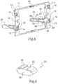
- it comprises a central sleeve 31 from which laterally leave two anchors formed by two diametrically opposed longitudinal horizontal arms 32 which each end with two elastic return tabs 33 substantially parallel to the arms 32.
- different form for example in the form shown in figure 6 which comprises a main body 35 of oval longitudinal section surmounted by two elastic fins 36 extending from the ends of the body and directed along from him, parallel to him, towards his center.
- the pin 30 is likely to be crushed slightly in height and it exerts in reaction a vertical resistance force.
- the housing 1 is intended to be housed in a compartment 10 only sketched on the figure 3 and formed in the dashboard of a vehicle.
- the compartment 10 is generally of standardized size designated by 1DIN for a single volume and 2DIN for a dual volume (as shown here, the housing 1 occupying only half).
- the compartment 10 comprises a front frame 11 intended to be fitted or fixed in the front opening 12 of the compartment 10.
- the front plate 6 of the housing is intended to be applied and positioned and to be fixed thanks to the reliefs 7 and the fastening lugs 8.
- the frame 11 has recesses or recesses 13 complementary to the reliefs 8 to receive and holes 14 cooperating with the holes 9 of the fastening lugs to allow screwing fixing screws.
- the frame 11 comprises at least two first side slide portions, or inlet drains 20, arranged longitudinally rearwardly and defining a guideway advantageously short and quickly convergent for the tenons 30 of the housing.
- Each drain 20 is formed of a bottom 21 and two convergent edges 22.
- the frame 11 has 4 drains 20, the two of the bottom for guiding the housing 1 shown, and both of which can be used to guide a second superimposed housing to the first.
- frame 11 of the figure 5 has only been planned with two drains 20.
- the second side slide portion 23 is separated from the first portion 20, but is disposed longitudinally thereafter and is secured by means not shown on the side walls 14 of the compartment 10.
- the second slide portion 23 is one or several parts and essentially comprises a generally horizontal guiding light formed between an upper profile or rail 24 and a lower profile or rail 25.
- the guiding light is open laterally on the inner side of the compartment 10 but is closed on the outside, at least in the end region of the slider portion 23.
- the height of the light decreases, for example in steps, from its inlet end to its farthest end.
- the rails 24, 25 have in effect a first short section rapid convergence 26 in which can be inserted into the rear end of the drains 20, to ensure continuity of guidance.
- This section 26 is followed by a first section of substantially constant height or weakly convergent, forming zone input and guide post, itself followed by a new short section fast convergence 27 (only the upper rail 24 participates here to the reduction of height of the light, the lower rail 25 remaining horizontal once the input section passed), finally followed by a new section 28 of substantially constant or weakly convergent height, forming the bottom and compression zone of tenon 30.
- FIGS. 2 to 4 illustrate three steps of the introduction of the housing 1 in the housing 10 and the cooperation of the tenons 30 in the horizontal rails 20, 23.
- the housing 1 is partially introduced into the compartment 10 and the post 30 is in the approach phase of the drain or first slide portion 20.
- the housing 1 continuing its depression, the generally horizontal tenon 30 began to be introduced into the second portion of slide 23 generally horizontal, in its first section of constant height, this height being greater than the free height of the tenon 30.
- the tenon 30 has continued to slide on the lower rail 225 of the light 21, has passed the second strongly convergent section 27 and has accessed the second section 28 of constant height, which is slightly less than the height height of the post 30. Therefore, when passing through the strongly convergent section 27, the rails 24,25 which are tightened bear on the elastic tabs 33 of the tenon 30 and the height of the anchors could decrease thanks to the elasticity of the tabs 33.
- the height of the anchors can decrease by 0.5 mm on each side, or 1 mm in all.
- the tenon 30 is made of a material such as a plastic, including a POM (polyoxymethylene).
Landscapes
- Engineering & Computer Science (AREA)
- Mechanical Engineering (AREA)
- Chemical & Material Sciences (AREA)
- Combustion & Propulsion (AREA)
- Transportation (AREA)
- Fittings On The Vehicle Exterior For Carrying Loads, And Devices For Holding Or Mounting Articles (AREA)
- Casings For Electric Apparatus (AREA)
Description
- La présente invention concerne un dispositif de montage d'un boîtier, notamment d'une radio, dans un compartiment de planche de bord d'un véhicule automobile.
- Le montage d'un boîtier de radio dans le compartiment prévu à cet effet dans la planche de bord d'un véhicule doit permettre de fixer correctement le poste dans toutes les directions. La cote verticale peut par exemple être donnée par la combinaison d'un pion placé à l'arrière du boîtier de radio avec des pions latéraux de rattrapage de jeu ; le pion arrière, central, pénètre dans un orifice correspondant situé au fond et au milieu du compartiment. Cependant, l'augmentation du nombre des connecteurs à l'arrière du boîtier, lié à l'augmentation des fonctions sur la radio, rend souhaitable de ne pas avoir à utiliser de pion arrière de centrage et d'assurer la cote verticale par d'autres moyens.
- Le document
US 5560572 comprend toutes les caractéristiques du préambule de la revendication 1 et fait connaître un dispositif de montage d'un boîtier présentant deux faces latérales parallèles sur chacune desquelles est disposé un organe mâle ou tenon, le dispositif comportant deux glissières latérales parallèles superposées formées dans des parois d'une cuvette de logement s'étendant à partir d'un cadre de façade bordant l'ouverture d'un compartiment de la planche de bord d'un véhicule ; les glissières forment un organe femelle ou mortaise orientée dans une direction sensiblement longitudinale et ayant une zone d'entrée et une zone de fond moins haute que la zone d'entrée ; le tenon comporte une partie élastiquement compressible destinée à pousser verticalement le tenon dans la mortaise lors de l'introduction du tenon dans la zone de fond étroite (basse) de sa mortaise correspondante. La construction de la mortaise en deux parties séparées et du tenon en deux parties également est relativement compliquée. - Selon une solution observée sur des véhicules de la marque Mercedes ®, il existe un dispositif de montage avec un seul tenon sur chaque face du boîtier, réalisé sous forme d'une pièce mâle ovale comportant une anse élastiquement écrasable formée par un évidement parallèle au bord supérieur de la pièce, et une seule mortaise convergente de chaque côté du compartiment : quand on engage chacun des tenons élastiques dans sa mortaise correspondante, la partie élastique se déforme, s'écrase élastiquement, et assure un placage en Z de la radio, ce qui permet nonmalement d'absorber les dispersions géométriques de la planche de bord.
- Dans l'un et l'autre des deux dispositifs ci-dessus, les glissières latérales coopérant avec les tenons latéraux sont formées d'un seul tenant et intégralement dans une paroi attenante à un cadre de montage en façade. On a constaté qu'il pouvait parfois en résulter des difficultés de montage de la radio dans le compartiment en raison des dispersions de fabrication lors du moulage des éléments.
- Le but de l'invention est d'offrir une solution alternative de glissières de montage qui facilite la fabrication et le montage du dispositif.
- L'invention atteint son but grâce à un dispositif de montage d'un boîtier dans un compartiment d'une planche de bord de véhicule comportant une ouverture d'insertion de boîtier, le boîtier présentant deux faces latérales parallèles sur chacune desquelles est disposé un tenon, le dispositif comportant deux glissières latérales parallèles fixes formant pour les tenons un chemin guidé dans une direction sensiblement longitudinale et ayant une zone d'entrée et une zone de fond moins haute que la zone d'entrée, chaque tenon comportant une partie élastiquement compressible destinée à pousser verticalement le tenon dans la glissière lorsque le tenon est dans la zone de fond de sa glissière correspondante, un cadre de façade étant prévu autour de l'ouverture d'insertion de boîtier pour coopérer au positionnement et/ou à la fixation d'une plaque de façade du boîtier, caractérisé en ce que les glissières latérales comprennent deux parties longitudinalement séparées, à savoir une première partie solidaire dudit cadre de façade et une seconde partie non solidaire du cadre de façade et maintenue sur une paroi du compartiment de planche de bord de manière à être sensiblement dans le prolongement longitudinal de la première partie.
- Grâce à cette disposition, on peut fabriquer plus facilement, notamment par moulage d'une matière plastique, le cadre de façade et la première partie de glissière, laquelle est avantageusement assez courte. La seconde partie est fabriquée séparément et est fixée indépendamment du cadre de façade.
- Le dispositif de l'invention présente avantageusement l'une ou l'autre des caractéristiques suivantes, seules ou en combinaison.
- la première partie de glissière comporte un fond et deux bordures convergentes.
- la seconde partie de glissière comporte une lumière formée par un rail supérieur et un rail inférieur convergents par paliers.
- la seconde partie de glissière comporte une première section à convergence rapide de raccordement à l'extrémité arrière de la première parte de glissière.
- la seconde partie de glissière comporte la zone de fond de hauteur inférieure à la hauteur libre d'un tenon.
- la seconde partie de glissière comporte comprend au voisinage de la zone de fond une paroi latérale.
- le tenon est constitué d'une partie centrale de laquelle partent deux bras symétriques opposés portant chacun deux pattes formant des ancres longitudinales symétriques par rapport à la partie centrale et élastiquement compressibles en hauteur.
- le tenon comprend un corps principal de section longitudinale ovale surmonté de deux ailettes élastiques partant des extrémités du corps et dirigées le long de celui-ci, parallèlement à lui, vers son centre.
- la plaque de montage du boîtier comporte des reliefs coopérant avec des reliefs complémentaires prévus dans la façade de montage entourant l'ouverture d'insertion.
- la plaque de montage du boîtier comporte des orifices de fixation coopérant avec des orifices de fixation prévus dans la façade de montage entourant l'ouverture d'insertion.
- D'autres caractéristiques et avantages de l'invention ressortiront de la description suivante d'un exemple de réalisation. Il sera fait référence aux dessins annexés sur lesquels :
- La
figure 1 est une vue schématique en perspective de trois-quarts arrière d'un poste de radio dont les faces latérales sont dotées des tenons élastiques conformes à l'invention. - La
figure 2 est une vue partielle en perspective de trois-quarts avant du boîtier de radio et d'une des deux glissières latérales du dispositif conforme à l'invention, lors d'une première étape de l'engagement du boîtier de radio dans le compartiment. - La
figure 3 est une vue partielle en perspective de trois-quarts avant du boîtier de radio et d'une des deux glissières latérales du dispositif conforme à l'invention, lors d'une seconde étape de l'engagement du boîtier de radio dans le compartiment. - La
figure 4 est une vue latérale partielle du tenon élastique dans la glissière latérale lors d'une dernière étape de l'engagement du boîtier de radio dans le compartiment. - La
figure 5 est une vue partielle en perspective d'une variante de cadre façade selon l'invention et des deux glissières latérales conformes à l'invention. - La
figure 6 est vue partielle en perspective d'une variante de tenon élastique. - Comme représenté sur les
figures 1 à 4 , le boîtier de radio 1 a une forme sensiblement parallélépipédique, avec une paroi avant verticale 2, deux parois latérales verticales 3, une paroi arrière verticale 4, un dessus 5 et un fond. On notera qu'on parle ici d'avant et d'arrière du boîtier de radio tel que vu par un conducteur qui a le boîtier de radio devant lui lorsqu'il est dans le véhicule ; dans un repère traditionnel X, Y, Z des directions longitudinale, transversale, et verticale, l'arrière du boîtier 1 est en fait vers l'avant du véhicule. - Une façade avant 6 est montée sur la paroi avant 2 du boîtier 1 (elle n'a été représentée que sur la
figure 1 ). Cette façade comprend une plaque à l'arrière de laquelle sont prévus d'une part des reliefs 7 de positionnement et des pattes 8 de fixation pourvues de trous 9 de fixation. - Les deux faces latérales 3 comprennent un tenon 30 protubérant, élastiquement compressible en hauteur. Dans cet exemple de réalisation, il comporte un manchon central 31 dont partent latéralement deux ancres formées par deux bras horizontaux longitudinaux 32 diamétralement opposés et qui se terminent chacun par deux pattes retournées élastiques 33 sensiblement parallèles aux bras 32. Le tenon peut être réalisé sous une forme différente, par exemple sous la forme représenté en
figure 6 , qui comprend un corps principal 35 de section longitudinale ovale surmonté de deux ailettes élastiques 36 partant des extrémités du corps et dirigées le long de celui-ci, parallèlement à lui, vers son centre. Dans ces deux modes de réalisation, le tenon 30 est susceptible d'être écrasé légèrement en hauteur et il exerce en réaction une force de résistance verticale. - Le boîtier 1 est destiné à se loger dans un compartiment 10 seulement esquissé sur la
figure 3 et formé dans la planche de bord d'un véhicule. Le compartiment 10 est généralement d'une taille standardisée désignée par 1DIN pour un volume simple et 2DIN pour un volume double (comme représenté ici, le boîtier 1 n'en occupant que la moitié). Le compartiment 10 comporte un cadre de façade 11 destiné à venir s'emboîter ou se fixer dans l'ouverture avant 12 du compartiment 10. Sur ce cadre 11, la plaque 6 de façade du boîtier est destinée à s'appliquer et à se positionner et se fixer grâce aux reliefs 7 et aux pattes de fixation 8. À cet effet, le cadre 11 comporte des évidements ou creux 13 complémentaires des reliefs 8 à recevoir et des trous 14 coopérant avec les trous 9 des pattes de fixation pour permettre le vissage de vis de fixation. - Conformément à l'invention, le cadre 11 comprend au moins deux premières parties de glissière latérale, ou avaloirs d'entrée 20, disposés longitudinalement vers l'arrière et définissant une piste de guidage avantageusement courte et rapidement convergente pour les tenons 30 du boîtier. Chaque avaloir 20 est formé d'un fond 21 et de deux bordures convergentes 22. Sur la
figure 3 , le cadre 11 comporte 4 avaloirs 20, les deux du bas servant au guidage du boîtier 1 représenté, et les deux du haut pouvant servir au guidage d'un second boîtier superposé au premier. Au contraire le cadre 11 de lafigure 5 n'a été prévu qu'avec deux avaloirs 20. - La seconde partie 23 de glissière latérale est séparée de la première partie 20, mais est disposée longitudinalement à sa suite et est fixée par des moyens non représentés sur les parois latérales 14 du compartiment 10.La seconde partie de glissière 23 est d'une ou plusieurs pièces et comporte essentiellement une lumière de guidage globalement horizontale formée entre un profil ou rail supérieur 24 et un profil ou rail inférieur 25. La lumière de guidage est ouverte latéralement du côté intérieur du compartiment 10 mais est fermée du côté extérieur, au moins dans la région d'extrémité de la partie de glissière 23. La hauteur de la lumière va en décroissant, par exemple par paliers, depuis son extrémité d'entrée jusqu'à son extrémité la plus éloignée. Les rails 24,25 comportent en effet une première section courte à convergence rapide 26 dans laquelle peut venir s'emboîter l'extrémité arrière des avaloirs 20, afin d'assurer la continuité du guidage. Cette section 26 est suivie d'une première section de hauteur sensiblement constante ou faiblement convergente, formant zone d'entrée et de guidage du tenon, elle-même suivie d'une nouvelle section courte à convergence rapide 27 (seul le rail supérieur 24 participe ici à la réduction de hauteur de la lumière, le rail inférieur 25 restant horizontal une fois la section d'entrée passée), enfin suivie d'une nouvelle section 28 de hauteur sensiblement constante ou faiblement convergente, formant la zone de fond et de compression du tenon 30.
- Les
figures 2 à 4 illustrent trois étapes de l'introduction du boîtier 1 dans le logement 10 et de la coopération des tenons 30 dans les glissières horizontales 20, 23. - Dans la
figure 2 , le boîtier 1 est partiellement introduit dans le compartiment 10 et le tenon 30 est en phase d'approche de l'avaloir ou première partie de glissière 20. - Dans la
figure 3 , le boîtier 1 poursuivant son enfoncement, le tenon globalement horizontal 30 a commencé à s'introduire dans la seconde partie de glissière 23 globalement horizontale, dans sa première section de hauteur constante, cette hauteur étant plus grande que la hauteur libre du tenon 30. - Dans la
figure 4 , le tenon 30 a continué à glisser sur le rail inférieur 225 de la lumière 21, a passé la seconde section fortement convergente 27 et a accédé à la seconde section 28 de hauteur constante, laquelle est de hauteur légèrement inférieure à la hauteur libre du tenon 30. Par conséquent, lors du passage dans la section fortement convergente 27, les rails 24,25 qui se resserrent appuient sur les pattes élastiques 33 du tenon 30 et la hauteur des ancres a pu diminuer grâce à l'élasticité des pattes 33. Dans un exemple particulier, la hauteur des ancres peut diminuer de 0,5 mm de chaque côté, soit 1 mm en tout. Dans cette section 28, qui est la section de fond de la glissière 20, 23, le boîtier 1 est parfaitement maintenu en hauteur grâce au placage équilibré effectué par les pattes 33 des deux ancres formées sur le tenon 30. - Grâce à sa forme générale sensiblement horizontale avec à ses extrémités deux parties symétriques compressibles élastiquement (les ancres formées par les pattes 33), le guidage du tenon 30 dans sa glissière 20,23 est excellent et équilibré.
- Pour assurer sa résistance et son élasticité, le tenon 30 est réalisé dans un matériau tel qu'une matière plastique, notamment un POM (polyoxyméthylène).
Claims (10)
- Dispositif de montage d'un boîtier (1) dans un compartiment (10) d'une planche de bord de véhicule comportant une ouverture (12) d'insertion de boîtier, le boîtier (1) présentant deux faces latérales parallèles (3) sur chacune desquelles est disposé un tenon (30), le dispositif comportant deux glissières latérales parallèles fixes (20, 23) formant pour les tenons (30) un chemin guidé dans une direction sensiblement longitudinale et ayant une zone d'entrée et une zone de fond moins haute que la zone d'entrée, chaque tenon (30) comportant une partie élastiquement compressible (33, 36) destinée à pousser verticalement le tenon (30) dans la glissière (20, 23) lorsque le tenon (30) est dans la zone de fond de sa glissière correspondante, un cadre de façade (11) étant prévu autour de l'ouverture (12) d'insertion de boîtier pour coopérer au positionnement et/ou à la fixation d'une plaque (6) de façade du boîtier (1), caractérisé en ce que les glissières latérales (20, 23) comprennent deux parties longitudinalement séparées, à savoir une première partie (20) solidaire dudit cadre de façade (11) et une seconde partie (23) non solidaire du cadre de façade (11) et maintenue sur une paroi du compartiment (10) de planche de bord de manière à être sensiblement dans le prolongement longitudinal de la première partie (20).
- Dispositif selon la revendication 1, caractérisé en ce que la première partie (20) de glissière comporte un fond (21) et deux bordures convergentes (22).
- Dispositif selon la revendication 1 ou 2, caractérisé en ce que la seconde partie (23) de glissière comporte une lumière formée par un rail supérieur (24) et un rail inférieur (25) convergents par paliers.
- Dispositif selon l'une quelconque des revendications 1 à 3, caractérisé en ce que la seconde partie (23) de glissière comporte une première section (26) à convergence rapide de raccordement à l'extrémité arrière de la première parte (20) de glissière.
- Dispositif selon l'une quelconque des revendications 1 à 4, caractérisé en ce que la seconde partie (23) de glissière comporte la zone de fond (28) de hauteur inférieure à la hauteur libre d'un tenon.
- Dispositif selon la revendication 5, caractérisé en ce que la seconde partie (23) de glissière comporte comprend au voisinage de la zone de fond (28) une paroi latérale.
- Dispositif selon lune quelconque des revendications 1 à 6, caractérisé en ce que le tenon (30) est constitué d'une partie centrale (31) de laquelle partent deux bras symétriques opposés (32) portant chacun deux pattes (33) formant des ancres longitudinales symétriques par rapport à la partie centrale (31) et élastiquement compressibles en hauteur.
- Dispositif selon lune quelconque des revendications 1 à 6, caractérisé en ce que le tenon (30) comprend un corps principal (35) de section longitudinale ovale surmonté de deux ailettes élastiques (36) partant des extrémités du corps (35) et dirigées le long de celui-ci, parallèlement à lui, vers son centre.
- Dispositif selon lune quelconque des revendications 1 à 8, caractérisé en ce que la plaque de montage (6) du boîtier (1) comporte des reliefs (7) coopérant avec des reliefs (13) complémentaires prévus dans la façade (11) de montage entourant l'ouverture d'insertion (12).
- Dispositif selon lune quelconque des revendications 1 à 9, caractérisé en ce que la plaque de montage (6) du boîtier (1) comporte des orifices de fixation (9) coopérant avec des orifices de fixation (14) prévus dans la façade (11) de montage entourant l'ouverture d'insertion (12).
Applications Claiming Priority (2)
| Application Number | Priority Date | Filing Date | Title |
|---|---|---|---|
| FR1252294A FR2988042B1 (fr) | 2012-03-14 | 2012-03-14 | Dispositif de montage d'un boitier, notamment d'une radio, dans un compartiment de planche de bord d'un vehicule automobile |
| PCT/EP2013/051919 WO2013135421A1 (fr) | 2012-03-14 | 2013-01-31 | Dispositif de montage d'un boîtier, notamment d'une radio, dans un compartiment de planche de bord d'un véhicule automobile |
Publications (2)
| Publication Number | Publication Date |
|---|---|
| EP2825410A1 EP2825410A1 (fr) | 2015-01-21 |
| EP2825410B1 true EP2825410B1 (fr) | 2016-03-30 |
Family
ID=47624106
Family Applications (1)
| Application Number | Title | Priority Date | Filing Date |
|---|---|---|---|
| EP13701666.3A Not-in-force EP2825410B1 (fr) | 2012-03-14 | 2013-01-31 | Dispositif de montage d'un boîtier, notamment d'une radio, dans un compartiment de planche de bord d'un véhicule automobile |
Country Status (5)
| Country | Link |
|---|---|
| US (1) | US9738235B2 (fr) |
| EP (1) | EP2825410B1 (fr) |
| FR (1) | FR2988042B1 (fr) |
| RU (1) | RU2605961C2 (fr) |
| WO (1) | WO2013135421A1 (fr) |
Families Citing this family (9)
| Publication number | Priority date | Publication date | Assignee | Title |
|---|---|---|---|---|
| FR2988042B1 (fr) * | 2012-03-14 | 2014-04-18 | Renault Sa | Dispositif de montage d'un boitier, notamment d'une radio, dans un compartiment de planche de bord d'un vehicule automobile |
| FR2988043B1 (fr) * | 2012-03-14 | 2014-11-21 | Renault Sa | Dispositif de montage d'un boitier, notamment d'une radio, dans un compartiment de planche de bord d'un vehicule automobile |
| DE102017003193A1 (de) * | 2017-04-01 | 2018-10-04 | Man Truck & Bus Ag | Vorrichtung, insbesondere zum Einbau in ein Kraftfahrzeug, mit einem Aufnahmeschacht |
| FR3066734B1 (fr) * | 2017-05-24 | 2019-07-05 | Renault S.A.S | Dispositif de fixation d'un boitier a une traverse de planche de bord. |
| CN108394350B (zh) * | 2018-02-24 | 2020-04-28 | 安徽江淮汽车集团股份有限公司 | 驾驶台设备组合装置 |
| DE102019204697B4 (de) * | 2019-04-02 | 2021-01-21 | Volkswagen Aktiengesellschaft | Vorrichtung zur Aufnahme einer Anzeige-Bedieneinrichtung |
| DE102019205344B4 (de) * | 2019-04-12 | 2024-05-16 | Volkswagen Aktiengesellschaft | Aufnahmesystem zur Aufnahme wenigstens einer geführten Einrichtung und ein Elektromodul, sowie ein Kraftfahrzeug |
| US11414024B2 (en) * | 2019-09-11 | 2022-08-16 | Calsonic Kansei North America, Inc. | Mounting arrangement and method of installing an audio unit in a vehicle dashboard |
| US20250346120A1 (en) * | 2024-05-08 | 2025-11-13 | Ford Global Technologies, Llc | Finish panel to house an nfc module |
Family Cites Families (9)
| Publication number | Priority date | Publication date | Assignee | Title |
|---|---|---|---|---|
| JPS587387U (ja) * | 1981-07-07 | 1983-01-18 | クラリオン株式会社 | 車載用ラック取付装置 |
| JPS58144886U (ja) * | 1982-03-25 | 1983-09-29 | アルパイン株式会社 | 車載音響機器用ラツクの取付装置 |
| US5560572A (en) * | 1994-09-26 | 1996-10-01 | General Motors Corporation | Instrument panel dovetail slide mounting assembly |
| TW467359U (en) * | 2000-07-14 | 2001-12-01 | Hon Hai Prec Ind Co Ltd | Sliding rail device of data access device |
| US6416025B1 (en) * | 2000-07-24 | 2002-07-09 | Toyota Technical Center Usa, Inc. | Part retainer |
| US7040686B2 (en) * | 2002-06-28 | 2006-05-09 | Collins & Aikman Products Co. | Integrated center stack electronic module retention system |
| DE10357799B4 (de) * | 2003-12-10 | 2006-11-23 | Siemens Ag | Adaptersystem |
| US7753423B2 (en) * | 2008-01-08 | 2010-07-13 | Toyota Motor Engineering & Manufacturing North America, Inc. | Component assembly for a motor vehicle |
| FR2988042B1 (fr) * | 2012-03-14 | 2014-04-18 | Renault Sa | Dispositif de montage d'un boitier, notamment d'une radio, dans un compartiment de planche de bord d'un vehicule automobile |
-
2012
- 2012-03-14 FR FR1252294A patent/FR2988042B1/fr not_active Expired - Fee Related
-
2013
- 2013-01-31 WO PCT/EP2013/051919 patent/WO2013135421A1/fr not_active Ceased
- 2013-01-31 RU RU2014141281A patent/RU2605961C2/ru active
- 2013-01-31 US US14/385,304 patent/US9738235B2/en not_active Expired - Fee Related
- 2013-01-31 EP EP13701666.3A patent/EP2825410B1/fr not_active Not-in-force
Also Published As
| Publication number | Publication date |
|---|---|
| RU2605961C2 (ru) | 2017-01-10 |
| WO2013135421A1 (fr) | 2013-09-19 |
| US9738235B2 (en) | 2017-08-22 |
| FR2988042A1 (fr) | 2013-09-20 |
| FR2988042B1 (fr) | 2014-04-18 |
| EP2825410A1 (fr) | 2015-01-21 |
| RU2014141281A (ru) | 2016-05-10 |
| US20150034774A1 (en) | 2015-02-05 |
Similar Documents
| Publication | Publication Date | Title |
|---|---|---|
| WO2013135421A1 (fr) | Dispositif de montage d'un boîtier, notamment d'une radio, dans un compartiment de planche de bord d'un véhicule automobile | |
| EP2825411B1 (fr) | Dispositif de montage d'un boitier, notamment d'une radio, dans un compartiment de planche de bord d'un vehicule automobile | |
| EP1879783B1 (fr) | Corps creux en matiere plastique, notamment pour l'habillage de colonnes de direction de vehicule automobile. | |
| EP2518336A1 (fr) | Ensemble d'assemblage de deux pièces de véhicule automobile | |
| EP3666568B1 (fr) | Kit et procédé d'habillage d'un rail de porte d'un véhicule | |
| FR3075125A1 (fr) | Dispositif de support pour appareil electronique portatif | |
| EP3735363A1 (fr) | Dispositif d'attache et de guidage pour faisceaux éléctriques cheminant entre un longeron et sa garniture d'habillage | |
| EP2055885A2 (fr) | Pièce de liaison et assemblage de profilés comportant une telle pièce | |
| EP3094523B1 (fr) | Véhicule doté d'un élément d'absorption de choc | |
| FR3021987B1 (fr) | Systeme de commande d'ouverture exterieure de porte de vehicule automobile | |
| EP3025914A1 (fr) | Dispositif de projection laterale d'un liquide de lavage pour un bras de balai pour systeme d essuyage d'une vitre d'un vehicule automobile | |
| EP1725438B1 (fr) | Moyens de fixation, sur une pièce de carrosserie, d'une trappe obturatrice d'une ouverture ménagée dans ladite pièce de carrosserie pour la saillie d'un organe mobile ainsi qu'un ensemble d'une trappe obturatrice et de tels moyens de fixation | |
| EP1914119A1 (fr) | Dispositif de rangement intérieur pour véhicule automobile | |
| FR3032657A1 (fr) | Glissiere pour siege de vehicule et siege de vehicule comportant une telle glissiere | |
| FR3143692A1 (fr) | Dispositif de montage d’un accessoire sur un element porteur detachable par appui sur l’accessoire | |
| EP3415365B1 (fr) | Systeme de guidage pour un meuble destine a etre monte en translation sur une paroi d'un vehicule de loisirs | |
| EP1518591A1 (fr) | Chassis de patin en ligne ou à glace et patin comprenant un tel chassis | |
| FR3155466A1 (fr) | Système assemblé de pièces et combiné d’affichage à éléments de fixation invisibles et affleurement réduit | |
| EP3209894B1 (fr) | Agencement d'une structure pour le montage d'une piece dans une ouverture au contour irregulier | |
| EP2329987A1 (fr) | Appui-tête de siège de véhicule automobile et son procédé de réalisation | |
| FR3026368A1 (fr) | Agencement de rangement suspendu sous le pavillon d'un vehicule | |
| FR3118742A1 (fr) | Rideau de fermeture d’un réceptacle | |
| FR3044283A1 (fr) | Implantation d'un marchepied sur un soubassement de vehicule automobile | |
| WO2021063816A1 (fr) | Sac à main comprenant un rabat interchangeable | |
| FR3012775A1 (fr) | Agencement interieur d'un vehicule automobile comportant un module de rangement amovible |
Legal Events
| Date | Code | Title | Description |
|---|---|---|---|
| PUAI | Public reference made under article 153(3) epc to a published international application that has entered the european phase |
Free format text: ORIGINAL CODE: 0009012 |
|
| 17P | Request for examination filed |
Effective date: 20140916 |
|
| AK | Designated contracting states |
Kind code of ref document: A1 Designated state(s): AL AT BE BG CH CY CZ DE DK EE ES FI FR GB GR HR HU IE IS IT LI LT LU LV MC MK MT NL NO PL PT RO RS SE SI SK SM TR |
|
| AX | Request for extension of the european patent |
Extension state: BA ME |
|
| DAX | Request for extension of the european patent (deleted) | ||
| GRAP | Despatch of communication of intention to grant a patent |
Free format text: ORIGINAL CODE: EPIDOSNIGR1 |
|
| INTG | Intention to grant announced |
Effective date: 20150925 |
|
| GRAS | Grant fee paid |
Free format text: ORIGINAL CODE: EPIDOSNIGR3 |
|
| GRAA | (expected) grant |
Free format text: ORIGINAL CODE: 0009210 |
|
| AK | Designated contracting states |
Kind code of ref document: B1 Designated state(s): AL AT BE BG CH CY CZ DE DK EE ES FI FR GB GR HR HU IE IS IT LI LT LU LV MC MK MT NL NO PL PT RO RS SE SI SK SM TR |
|
| REG | Reference to a national code |
Ref country code: GB Ref legal event code: FG4D Free format text: NOT ENGLISH |
|
| REG | Reference to a national code |
Ref country code: CH Ref legal event code: EP |
|
| REG | Reference to a national code |
Ref country code: AT Ref legal event code: REF Ref document number: 784966 Country of ref document: AT Kind code of ref document: T Effective date: 20160415 |
|
| REG | Reference to a national code |
Ref country code: IE Ref legal event code: FG4D Free format text: LANGUAGE OF EP DOCUMENT: FRENCH |
|
| REG | Reference to a national code |
Ref country code: DE Ref legal event code: R096 Ref document number: 602013005926 Country of ref document: DE |
|
| REG | Reference to a national code |
Ref country code: LT Ref legal event code: MG4D |
|
| PG25 | Lapsed in a contracting state [announced via postgrant information from national office to epo] |
Ref country code: FI Free format text: LAPSE BECAUSE OF FAILURE TO SUBMIT A TRANSLATION OF THE DESCRIPTION OR TO PAY THE FEE WITHIN THE PRESCRIBED TIME-LIMIT Effective date: 20160330 Ref country code: HR Free format text: LAPSE BECAUSE OF FAILURE TO SUBMIT A TRANSLATION OF THE DESCRIPTION OR TO PAY THE FEE WITHIN THE PRESCRIBED TIME-LIMIT Effective date: 20160330 Ref country code: NO Free format text: LAPSE BECAUSE OF FAILURE TO SUBMIT A TRANSLATION OF THE DESCRIPTION OR TO PAY THE FEE WITHIN THE PRESCRIBED TIME-LIMIT Effective date: 20160630 Ref country code: GR Free format text: LAPSE BECAUSE OF FAILURE TO SUBMIT A TRANSLATION OF THE DESCRIPTION OR TO PAY THE FEE WITHIN THE PRESCRIBED TIME-LIMIT Effective date: 20160701 |
|
| REG | Reference to a national code |
Ref country code: NL Ref legal event code: MP Effective date: 20160330 |
|
| REG | Reference to a national code |
Ref country code: AT Ref legal event code: MK05 Ref document number: 784966 Country of ref document: AT Kind code of ref document: T Effective date: 20160330 |
|
| PG25 | Lapsed in a contracting state [announced via postgrant information from national office to epo] |
Ref country code: SE Free format text: LAPSE BECAUSE OF FAILURE TO SUBMIT A TRANSLATION OF THE DESCRIPTION OR TO PAY THE FEE WITHIN THE PRESCRIBED TIME-LIMIT Effective date: 20160330 Ref country code: LV Free format text: LAPSE BECAUSE OF FAILURE TO SUBMIT A TRANSLATION OF THE DESCRIPTION OR TO PAY THE FEE WITHIN THE PRESCRIBED TIME-LIMIT Effective date: 20160330 Ref country code: LT Free format text: LAPSE BECAUSE OF FAILURE TO SUBMIT A TRANSLATION OF THE DESCRIPTION OR TO PAY THE FEE WITHIN THE PRESCRIBED TIME-LIMIT Effective date: 20160330 Ref country code: RS Free format text: LAPSE BECAUSE OF FAILURE TO SUBMIT A TRANSLATION OF THE DESCRIPTION OR TO PAY THE FEE WITHIN THE PRESCRIBED TIME-LIMIT Effective date: 20160330 |
|
| PG25 | Lapsed in a contracting state [announced via postgrant information from national office to epo] |
Ref country code: NL Free format text: LAPSE BECAUSE OF FAILURE TO SUBMIT A TRANSLATION OF THE DESCRIPTION OR TO PAY THE FEE WITHIN THE PRESCRIBED TIME-LIMIT Effective date: 20160330 |
|
| PG25 | Lapsed in a contracting state [announced via postgrant information from national office to epo] |
Ref country code: PL Free format text: LAPSE BECAUSE OF FAILURE TO SUBMIT A TRANSLATION OF THE DESCRIPTION OR TO PAY THE FEE WITHIN THE PRESCRIBED TIME-LIMIT Effective date: 20160330 Ref country code: IS Free format text: LAPSE BECAUSE OF FAILURE TO SUBMIT A TRANSLATION OF THE DESCRIPTION OR TO PAY THE FEE WITHIN THE PRESCRIBED TIME-LIMIT Effective date: 20160730 Ref country code: EE Free format text: LAPSE BECAUSE OF FAILURE TO SUBMIT A TRANSLATION OF THE DESCRIPTION OR TO PAY THE FEE WITHIN THE PRESCRIBED TIME-LIMIT Effective date: 20160330 |
|
| PG25 | Lapsed in a contracting state [announced via postgrant information from national office to epo] |
Ref country code: AT Free format text: LAPSE BECAUSE OF FAILURE TO SUBMIT A TRANSLATION OF THE DESCRIPTION OR TO PAY THE FEE WITHIN THE PRESCRIBED TIME-LIMIT Effective date: 20160330 Ref country code: PT Free format text: LAPSE BECAUSE OF FAILURE TO SUBMIT A TRANSLATION OF THE DESCRIPTION OR TO PAY THE FEE WITHIN THE PRESCRIBED TIME-LIMIT Effective date: 20160801 Ref country code: SK Free format text: LAPSE BECAUSE OF FAILURE TO SUBMIT A TRANSLATION OF THE DESCRIPTION OR TO PAY THE FEE WITHIN THE PRESCRIBED TIME-LIMIT Effective date: 20160330 Ref country code: CZ Free format text: LAPSE BECAUSE OF FAILURE TO SUBMIT A TRANSLATION OF THE DESCRIPTION OR TO PAY THE FEE WITHIN THE PRESCRIBED TIME-LIMIT Effective date: 20160330 Ref country code: SM Free format text: LAPSE BECAUSE OF FAILURE TO SUBMIT A TRANSLATION OF THE DESCRIPTION OR TO PAY THE FEE WITHIN THE PRESCRIBED TIME-LIMIT Effective date: 20160330 Ref country code: ES Free format text: LAPSE BECAUSE OF FAILURE TO SUBMIT A TRANSLATION OF THE DESCRIPTION OR TO PAY THE FEE WITHIN THE PRESCRIBED TIME-LIMIT Effective date: 20160330 Ref country code: RO Free format text: LAPSE BECAUSE OF FAILURE TO SUBMIT A TRANSLATION OF THE DESCRIPTION OR TO PAY THE FEE WITHIN THE PRESCRIBED TIME-LIMIT Effective date: 20160330 |
|
| REG | Reference to a national code |
Ref country code: DE Ref legal event code: R097 Ref document number: 602013005926 Country of ref document: DE |
|
| REG | Reference to a national code |
Ref country code: FR Ref legal event code: PLFP Year of fee payment: 5 |
|
| PG25 | Lapsed in a contracting state [announced via postgrant information from national office to epo] |
Ref country code: DK Free format text: LAPSE BECAUSE OF FAILURE TO SUBMIT A TRANSLATION OF THE DESCRIPTION OR TO PAY THE FEE WITHIN THE PRESCRIBED TIME-LIMIT Effective date: 20160330 |
|
| PLBE | No opposition filed within time limit |
Free format text: ORIGINAL CODE: 0009261 |
|
| STAA | Information on the status of an ep patent application or granted ep patent |
Free format text: STATUS: NO OPPOSITION FILED WITHIN TIME LIMIT |
|
| 26N | No opposition filed |
Effective date: 20170103 |
|
| PG25 | Lapsed in a contracting state [announced via postgrant information from national office to epo] |
Ref country code: BE Free format text: LAPSE BECAUSE OF NON-PAYMENT OF DUE FEES Effective date: 20170131 Ref country code: SI Free format text: LAPSE BECAUSE OF FAILURE TO SUBMIT A TRANSLATION OF THE DESCRIPTION OR TO PAY THE FEE WITHIN THE PRESCRIBED TIME-LIMIT Effective date: 20160330 |
|
| REG | Reference to a national code |
Ref country code: CH Ref legal event code: PL |
|
| PG25 | Lapsed in a contracting state [announced via postgrant information from national office to epo] |
Ref country code: MC Free format text: LAPSE BECAUSE OF FAILURE TO SUBMIT A TRANSLATION OF THE DESCRIPTION OR TO PAY THE FEE WITHIN THE PRESCRIBED TIME-LIMIT Effective date: 20160330 |
|
| PG25 | Lapsed in a contracting state [announced via postgrant information from national office to epo] |
Ref country code: CH Free format text: LAPSE BECAUSE OF NON-PAYMENT OF DUE FEES Effective date: 20170131 Ref country code: LI Free format text: LAPSE BECAUSE OF NON-PAYMENT OF DUE FEES Effective date: 20170131 |
|
| REG | Reference to a national code |
Ref country code: IE Ref legal event code: MM4A |
|
| PG25 | Lapsed in a contracting state [announced via postgrant information from national office to epo] |
Ref country code: LU Free format text: LAPSE BECAUSE OF NON-PAYMENT OF DUE FEES Effective date: 20170131 |
|
| REG | Reference to a national code |
Ref country code: FR Ref legal event code: PLFP Year of fee payment: 6 |
|
| REG | Reference to a national code |
Ref country code: BE Ref legal event code: MM Effective date: 20170131 |
|
| PG25 | Lapsed in a contracting state [announced via postgrant information from national office to epo] |
Ref country code: IE Free format text: LAPSE BECAUSE OF NON-PAYMENT OF DUE FEES Effective date: 20170131 |
|
| PG25 | Lapsed in a contracting state [announced via postgrant information from national office to epo] |
Ref country code: MT Free format text: LAPSE BECAUSE OF FAILURE TO SUBMIT A TRANSLATION OF THE DESCRIPTION OR TO PAY THE FEE WITHIN THE PRESCRIBED TIME-LIMIT Effective date: 20160330 |
|
| PG25 | Lapsed in a contracting state [announced via postgrant information from national office to epo] |
Ref country code: AL Free format text: LAPSE BECAUSE OF FAILURE TO SUBMIT A TRANSLATION OF THE DESCRIPTION OR TO PAY THE FEE WITHIN THE PRESCRIBED TIME-LIMIT Effective date: 20160330 |
|
| PG25 | Lapsed in a contracting state [announced via postgrant information from national office to epo] |
Ref country code: HU Free format text: LAPSE BECAUSE OF FAILURE TO SUBMIT A TRANSLATION OF THE DESCRIPTION OR TO PAY THE FEE WITHIN THE PRESCRIBED TIME-LIMIT; INVALID AB INITIO Effective date: 20130131 |
|
| PG25 | Lapsed in a contracting state [announced via postgrant information from national office to epo] |
Ref country code: BG Free format text: LAPSE BECAUSE OF FAILURE TO SUBMIT A TRANSLATION OF THE DESCRIPTION OR TO PAY THE FEE WITHIN THE PRESCRIBED TIME-LIMIT Effective date: 20160330 |
|
| PG25 | Lapsed in a contracting state [announced via postgrant information from national office to epo] |
Ref country code: CY Free format text: LAPSE BECAUSE OF FAILURE TO SUBMIT A TRANSLATION OF THE DESCRIPTION OR TO PAY THE FEE WITHIN THE PRESCRIBED TIME-LIMIT Effective date: 20160330 |
|
| PG25 | Lapsed in a contracting state [announced via postgrant information from national office to epo] |
Ref country code: MK Free format text: LAPSE BECAUSE OF FAILURE TO SUBMIT A TRANSLATION OF THE DESCRIPTION OR TO PAY THE FEE WITHIN THE PRESCRIBED TIME-LIMIT Effective date: 20160330 |
|
| PG25 | Lapsed in a contracting state [announced via postgrant information from national office to epo] |
Ref country code: TR Free format text: LAPSE BECAUSE OF FAILURE TO SUBMIT A TRANSLATION OF THE DESCRIPTION OR TO PAY THE FEE WITHIN THE PRESCRIBED TIME-LIMIT Effective date: 20160330 |
|
| P01 | Opt-out of the competence of the unified patent court (upc) registered |
Effective date: 20230608 |
|
| REG | Reference to a national code |
Ref country code: DE Ref legal event code: R079 Ref document number: 602013005926 Country of ref document: DE Free format text: PREVIOUS MAIN CLASS: B60K0037040000 Ipc: B60K0035500000 |
|
| PGFP | Annual fee paid to national office [announced via postgrant information from national office to epo] |
Ref country code: DE Payment date: 20240119 Year of fee payment: 12 Ref country code: GB Payment date: 20240123 Year of fee payment: 12 |
|
| PGFP | Annual fee paid to national office [announced via postgrant information from national office to epo] |
Ref country code: IT Payment date: 20240129 Year of fee payment: 12 Ref country code: FR Payment date: 20240122 Year of fee payment: 12 |
|
| REG | Reference to a national code |
Ref country code: DE Ref legal event code: R119 Ref document number: 602013005926 Country of ref document: DE |
|
| GBPC | Gb: european patent ceased through non-payment of renewal fee |
Effective date: 20250131 |
|
| PG25 | Lapsed in a contracting state [announced via postgrant information from national office to epo] |
Ref country code: DE Free format text: LAPSE BECAUSE OF NON-PAYMENT OF DUE FEES Effective date: 20250801 |
|
| PG25 | Lapsed in a contracting state [announced via postgrant information from national office to epo] |
Ref country code: GB Free format text: LAPSE BECAUSE OF NON-PAYMENT OF DUE FEES Effective date: 20250131 |
|
| PG25 | Lapsed in a contracting state [announced via postgrant information from national office to epo] |
Ref country code: FR Free format text: LAPSE BECAUSE OF NON-PAYMENT OF DUE FEES Effective date: 20250131 |
|
| PG25 | Lapsed in a contracting state [announced via postgrant information from national office to epo] |
Ref country code: IT Free format text: LAPSE BECAUSE OF NON-PAYMENT OF DUE FEES Effective date: 20250131 |