EP2825267B1 - Fire suppressing materials and systems - Google Patents
Fire suppressing materials and systems Download PDFInfo
- Publication number
- EP2825267B1 EP2825267B1 EP13813530.6A EP13813530A EP2825267B1 EP 2825267 B1 EP2825267 B1 EP 2825267B1 EP 13813530 A EP13813530 A EP 13813530A EP 2825267 B1 EP2825267 B1 EP 2825267B1
- Authority
- EP
- European Patent Office
- Prior art keywords
- fire suppressant
- mixture
- organic
- fire
- boiling point
- Prior art date
- Legal status (The legal status is an assumption and is not a legal conclusion. Google has not performed a legal analysis and makes no representation as to the accuracy of the status listed.)
- Active
Links
Images

Classifications
-
- A—HUMAN NECESSITIES
- A62—LIFE-SAVING; FIRE-FIGHTING
- A62D—CHEMICAL MEANS FOR EXTINGUISHING FIRES OR FOR COMBATING OR PROTECTING AGAINST HARMFUL CHEMICAL AGENTS; CHEMICAL MATERIALS FOR USE IN BREATHING APPARATUS
- A62D1/00—Fire-extinguishing compositions; Use of chemical substances in extinguishing fires
- A62D1/0092—Gaseous extinguishing substances, e.g. liquefied gases, carbon dioxide snow
-
- A—HUMAN NECESSITIES
- A62—LIFE-SAVING; FIRE-FIGHTING
- A62C—FIRE-FIGHTING
- A62C13/00—Portable extinguishers which are permanently pressurised or pressurised immediately before use
- A62C13/62—Portable extinguishers which are permanently pressurised or pressurised immediately before use with a single permanently pressurised container
-
- A—HUMAN NECESSITIES
- A62—LIFE-SAVING; FIRE-FIGHTING
- A62C—FIRE-FIGHTING
- A62C35/00—Permanently-installed equipment
- A62C35/02—Permanently-installed equipment with containers for delivering the extinguishing substance
-
- A—HUMAN NECESSITIES
- A62—LIFE-SAVING; FIRE-FIGHTING
- A62D—CHEMICAL MEANS FOR EXTINGUISHING FIRES OR FOR COMBATING OR PROTECTING AGAINST HARMFUL CHEMICAL AGENTS; CHEMICAL MATERIALS FOR USE IN BREATHING APPARATUS
- A62D1/00—Fire-extinguishing compositions; Use of chemical substances in extinguishing fires
- A62D1/0007—Solid extinguishing substances
- A62D1/0014—Powders; Granules
-
- A—HUMAN NECESSITIES
- A62—LIFE-SAVING; FIRE-FIGHTING
- A62D—CHEMICAL MEANS FOR EXTINGUISHING FIRES OR FOR COMBATING OR PROTECTING AGAINST HARMFUL CHEMICAL AGENTS; CHEMICAL MATERIALS FOR USE IN BREATHING APPARATUS
- A62D1/00—Fire-extinguishing compositions; Use of chemical substances in extinguishing fires
- A62D1/0028—Liquid extinguishing substances
- A62D1/0057—Polyhaloalkanes
Definitions
- the present patent document relates to fire suppressing materials and systems, and methods of using fire suppressing materials. More particularly, the present patent document relates to forming a mixture of an organic fire suppressant with another organic compound to modify a characteristic of the fire suppressant.
- Aircraft operating conditions provide unique challenges for the design of aircraft fire suppression systems.
- aircraft fire suppression systems must work at a wide range of temperatures. These temperature may range from +105° C when the aircraft is on the tarmac on a hot day, to as low as -55° C when the aircraft is at high altitudes.
- Halon 1301 has been the agent of choice for aircraft engine, auxiliary power unit (APU), and cargo fire suppression applications.
- Halon 1301 has a number of specific desirable properties that make it a popular choice for aircraft fire suppression systems.
- Halon 1301 has a low boiling point and a high vapor pressure, which facilitates agent-air mixing and distribution throughout the fire zone.
- the -58°C boiling point of Halon 1301 and its ability to freely vaporize at each point of discharge are desirable physical properties.
- ozone depleting potential of Halon 1301 (Bromotrifluoromethane)
- manufacturing of the material ceased in most countries in 1995.
- Halon 1301 is stored in a pressurized bottle, which uses nitrogen as a pressurizing gas. Nitrogen pressure beyond the natural vapor pressure of Halon 1301 is needed to provide system discharge energy at low temperatures. Nitrogen dissolved in the Halon solution also improves vaporization and breakup of liquid drops of Halon 1301 at low temperature similar to a "popcorn" effect.
- Aircraft fire suppression systems are usually designed based on the weight of the agent required to achieve a specific minimum agent concentration in the fire zone immediately after the bottle discharges.
- the fire suppression system should be designed to function properly at the minimum operating temperature for the application.
- the minimum operating temperature is often the worst case scenario for the fire suppression system because agent vapor volume and vapor pressure decrease with decreasing temperature.
- Agent distribution throughout the fire zone depends on the agent's ability to mix with air entering the fire zone at each discharge location.
- the presence of clutter in the fire zone may present challenges to the line-of-sight transport between the discharge location and the fire threat.
- an object according to one aspect of the present patent document is to provide a fire suppressant mixture.
- methods and systems related thereto are provided.
- the provided methods, systems, and mixtures address, or at least ameliorate one or more of the problems described above.
- a fire suppressant mixture is provided as set out in claim 1.
- the fire suppressant mixture of the invention comprises an organic fire suppressant compound selected from the group consisting of FK 5-1-12 and 2-BTP. In still other embodiments of the fire suppressant mixture, more than one organic fire suppressant compound may be used.
- the fire suppressant mixture contains an organic compound with a boiling point below that of the included organic fire suppressant compound, the organic compound being carbon dioxide.
- the organic compound may be mixed in any proportion with the organic fire suppressant. In a preferred embodiment, the mixture has an approximately 4 to 1 mass ratio of organic fire suppressant to organic compound.
- the fire suppressant mixture that is formed is pressurized by an inorganic gas.
- the inorganic pressurizing gas is Nitrogen. In other embodiments it may be argon or helium or some other inert gas.
- the components of the fire suppressant mixture may be selected for particular characteristics or qualities they posses.
- the components of the mixture may be selected based on environmental factors such as ozone depletion potential (ODP) and global warming potential (GWP).
- ODP ozone depletion potential
- GWP global warming potential
- the mixture may include an organic fire suppressant with an ODP of zero and a GWP of 1 or less.
- the present disclosure also includes a method of creating a fire suppressant mixture.
- the method comprises the steps of: mixing an organic fire suppressant having a boiling point with a halogen element to produce a mixture, mixing the mixture with an organic compound having a lower boiling point than the boiling point of the organic fire suppressant to form a fire suppressant mixture having a boiling point lower than the boiling point of the organic fire suppressant compound.
- tubing may be used to distribute the fire suppression mixture to a discharge location.
- the geometry of the tubing may be designed to maintain a minimum pressure within the fire suppression system.
- the fire suppression system includes distribution tubing and discharge geometries in communication with the distribution tubing at a plurality of discharge points, wherein the discharge exit geometry maintains a minimum pressure within the fire suppression system.
- the discharge exit geometry comprises a nozzle that restricts the flow of the fire suppression mixture.
- the fire suppressant mixtures, systems, and methods described herein provide suitable alternatives to existing fire suppressants, particularly when used in cold temperature environments, such as those found in aircraft. Further aspects, objects, desirable features, and advantages of the mixtures, systems and methods disclosed herein will be better understood from the detailed description and drawings that follow in which various embodiments are illustrated by way of example. It is to be expressly understood, however, that the drawings are for the purpose of illustration only and are not intended as a definition of the limits of the claimed invention.
- the present patent document teaches the use of an organic blend of compounds to create a fire suppression agent.
- an organic blend of compounds comprised from component compounds, it is possible to create a mixture that retains desirable characteristics of each of its components.
- fire suppressing agents may be formed that have numerous desirable features of their components and are thus better suited to handle fire suppression in diverse environments like the ones found on aircraft.
- Blending component compounds together also means that a wider range of compounds may be used because all the desirable features do not necessarily have to be exhibited by a single component.
- an organic fire suppressant may be blended with a compatible compound to modify a physical property of the organic fire suppressant and make it more suitable for a particular application.
- an organic fire suppressant compound selected from the group consisting of FK 5-1-12 and 2-BTP is mixed with an organic compound, said organic compound being carbon dioxide
- further organic fire suppressants may be included in the components of the mixture or further organic compounds may be included in the components of the mixture.
- further organic fire suppressant compounds may be combined with a single organic compound, said organic compound being carbon dioxide.
- a single organic fire suppressant compound selected from the group consisting of FK 5-1-12 and 2-BTP may be combined with further organic compounds.
- further organic fire suppressant compounds may be combined with further organic compounds.
- additional chemical elements may be mixed with the fire suppressant compound in some embodiments.
- at least one chemical element may be mixed with the fire suppressant compound.
- a preferred chemical element is a halogen element.
- organic compound is used broadly to refer to any compound that includes carbon whether or not the organic compound would be considered a fire suppressant.
- the organic compound has fire suppressant characteristics.
- halogen element is used to refer to the elements in the periodic table in group 7A including fluorine (F), chorine (Cl), bromine (Br), iodine (I).
- component compounds may be blended together to improve various different characteristics.
- an organic fire suppressant compound is mixed with an organic compound, said organic compound being carbon dioxide, to lower the boiling point of the resultant mixture.
- other characteristics may be improved or modified.
- the components of the mixture are chosen such that the resultant mixture exhibits characteristics of improved fire suppression effectiveness and airborne weight efficiency.
- the characteristics of each component may be selected to achieve a resultant mixture with specific characteristics.
- One characteristic that may be considered in an embodiment of a new fire suppression agent is ozone depletion potential (ODP).
- ODP ozone depletion potential
- the component compounds comprising the mixture have a lower ODP than Halon 1301 or at least are chosen such that the resultant mixture has an ODP less than Halon 1301.
- the component compounds comprising the mixture have half or less the ODP of Halon 1301 or result in a mixture with half or less the ODP of Halon 1301.
- component compounds may be selected that have little or no ODP, ODP of 1 or less, and result in a mixture with an ODP of 1 or less.
- component compounds are used that have an ODP of zero thus resulting in a mixture with an ODP of zero.
- the Global Warming Potential is an index that provides a relative measure of the possible climate impact due to a compound, which acts as a greenhouse gas in the atmosphere.
- the GWP of a compound as defined by the Intergovernmental Panel on Climate Change (IPCC), is calculated as the integrated radiative forcing due to the release of 1 kilogram of that compound relative to the warming due to 1 kilogram of CO 2 over a specified period of time (the integration time horizon (ITH)).
- the commonly accepted ITH is 100 years representing a compromise between short-term effects (20 years) and longer-term effects (500 years or longer).
- concentration of an organic compound, x in the atmosphere is assumed to follow pseudo first order kinetics (i.e., exponential decay).
- concentration of CO 2 over that same time interval incorporates a more complex model for the exchange and removal of CO 2 from the atmosphere (the Bern carbon cycle model).
- HFCs Hydrofluorocarbons
- PFCs perfluorocarbons
- IR infrared
- the radiative forcing values for PFCs and HFCs scale essentially linearly with the number of carbon-fluorine bonds due to the specific IR absorbance of those bonds at nominally 8 ⁇ m (1250 cm -1 ).
- the component compounds comprising the mixture have a lower GWP than Halon 1301 and thus, the resultant mixture has a GWP less than Halon 1301.
- the component compounds comprising the mixture have half or less the GWP of Halon 1301 resulting in a mixture with half or less the GWP of Halon 1301.
- component compounds are used that have a GWP of 1 thus resulting in a mixture with a GWP of 1.
- component compounds that may be considered include but are not limited to a components fire suppression capability, toxicity to humans, destructive capability towards the zone it is being used to protect, and any other important fire suppression, retarding, or extinguishing properties.
- organic fire suppression compounds that are environmentally friendly.
- FK-5-1-12, dodecafluoro-2-methylpentane-3-one, C 6 F 12 O, fluid is an environmentally friendly (ODP 0) fire suppression agent manufactured by 3M®.
- Organic fire suppressants include but are not limited to FK-5-1-12, dodecafluoro-2-methylpentan-one, CF 3 I, compounds similar to or derived from FK-5-1-12 and CF 3 I, large high molecular weight organic molecules containing a halogen with boiling point temperature below that of FK-5-1-12, HFC-125, 2,2-Dichloro-1,1,1-trifluoroethane (R123), and other organics that may be used as fire suppressants, retardants, or extinguishers.
- further organic fire suppressants may be either halogenated or non-halogenated.
- components may be selected that in isolation have good fire suppressant qualities.
- a component may be used that is not known to be a fire suppressant but has some other desirable quality that will enhance the effectiveness of the mixture.
- component compounds may be used that in isolation are not fire suppressants but when mixed together create a mixture with fire suppressant characteristics.
- FK-5-1-12, dodecafluoro-2-methylpentan-one is a high molecular weight material, compared with the first generation halocarbon clean agents.
- the product has a heat of vaporization of 88.1 kJ/kg and low vapor pressure. Although it is a liquid at room temperature, under normal temperatures it gasifies immediately after being discharged in a total flooding system.
- Trifluoroiodomethane also referred to as trifluoromethyl iodide.
- Trifluoroiodomethane is a halomethane with the formula CF 3 I. It contains carbon, fluorine, and iodine atoms. Although iodine is several hundred times more efficient at destroying stratospheric ozone than chlorine, experiments have shown that because the weak C-I bond breaks easily under the influence of water (owing to the electron-attracting fluorine atoms), trifluoroiodomethane has an ozone depleting potential less than one-thousandth that of Halon 1301 (0.008-0.01). Its atmospheric lifetime, at less than 1 month, is less than 1 percent that of Halon 1301.
- the problem with FK-5-1-12 and CF 3 I in isolation is that they have relatively high normal boiling points.
- the boiling point of a substance is the temperature at which the vapor pressure of the liquid equals the environmental pressure surrounding the liquid.
- a liquid in a vacuum has a lower boiling point than when that liquid is at sea level atmospheric pressure.
- a liquid at high-pressure has a higher boiling point than when that liquid is at sea level atmospheric pressure.
- the boiling point of a liquid varies depending upon the surrounding environmental pressure. For a given pressure, different liquids boil at different temperatures.
- the normal boiling point (also called the atmospheric boiling point or the atmospheric pressure boiling point) of a liquid is the special case in which the vapor pressure of the liquid equals the defined atmospheric pressure at sea level, 1 atmosphere. At that temperature, the vapor pressure of the liquid becomes sufficient to overcome atmospheric pressure and allow bubbles of vapor to form inside the bulk of the liquid.
- the standard boiling point is now (as of 1982) defined by IUPAC as the temperature at which boiling occurs under a pressure of 1 bar.
- High boiling point agents such as FK 5-1-12 (normal boiling point of 49°C) and CF 3 I (normal boiling point of -23°C) do not freely vaporize below each respective boiling temperature. Consequently, in cold temperature environments like those found on an airplane at altitude, agent distribution must rely on atomization by mechanical treatment, or sheer momentum. This makes FK 5-1-12 and CF 3 I less than ideal replacements for Halon as aircraft fire suppressants when used by themselves. However, in embodiments of the present patent document, FK 5-1-12 is blended with carbon dioxide to modify their boiling point and thus, increase their effectiveness as fire suppressants in cold environments.
- FK 5-1-12 is blended with another organic compound with a lower boiling point, said organic compound being carbon dioxide, to lower the boiling point of the organic fire suppressant.
- the result of the mixture due to both materials being organic compounds and miscible within each other, is a liquid phase exhibiting a boiling point between that of the organic fire suppressant and the organic compound mixed with the organic fire suppressant.
- the boiling point of a mixture is a function of the vapor pressures of the various components in the mixture.
- vapor pressures of liquids at ambient temperatures increase with decreasing boiling points.
- the term p i ⁇ i is the partial pressure of component i in the mixture.
- Raoult's Law is applicable only to non-electrolytes (uncharged species); it is most appropriate for non-polar molecules with only weak intermolecular attractions (such as London forces).
- an organic fire suppressant compound is mixed with a second organic compound with a lower boiling point to create a fire suppressant mixture with a lower boiling point than that of the organic fire suppressant compound.
- the fire suppressant mixture has little to no ODP and a low GWP. The lower boiling point improves free vaporization characteristics of the mixture.
- the boiling point of the mixture is between 1 and 40 degrees Celsius lower than the boiling point of the organic fire suppressant compound by itself. In a more preferred embodiment, the boiling point of the mixture is between 40 and 75 degrees Celsius lower than the boiling point of the organic fire suppressant compound by itself. In an even more preferable embodiment, the boiling point of the mixture is between 75 and 100 degrees Celsius lower than the boiling point of the organic fire suppressant compound by itself.
- organic compounds may be mixed with the organic fire suppressant to modify various different characteristics of the organic fire suppressant.
- the organic compound that is used is CO 2 .
- other organic compounds that exhibit desirable characteristics are also discussed herein.
- FK 5-1-12 is mixed with carbon dioxide (CO 2 ).
- CO 2 carbon dioxide
- the boiling point of CO 2 at standard atmospheric pressure is -78.5° C.
- Novec 1230 which has a boiling point of 49° C, the added CO 2 will lower the boiling point of the total mixture.
- CO 2 may also be used as a fire suppressant and is environmentally friendly.
- CO 2 in large enough quantities to be a fire suppressant by itself is toxic to humans.
- the resultant mixture exhibits the advantageous properties of both of its components. Namely, an environmentally friendly fire suppressant with a lower boiling point that is safe for use around humans. The lower boiling point improves the mixtures free vaporization characteristics and helps it disperse better in air at cold temperatures and flood the area for which fire suppression is desired.
- different quantities of organic fire suppressants and organic compounds may be mixed together. These quantities may be determined based on the specific application the fire suppressant mixture is designed to be used in. For example, a requirement that the system be effective down to -60° C may require more CO 2 to be added to the organic fire suppressant than if the environmental requirement were less extreme.
- Fig. 1 illustrates how the vapor pressure of a mixture changes with the mole fraction of each of the components in the mixture.
- the boiling point typically follows an inverse relationship to the vapor pressure.
- the solid lines represent the partial pressure of FK 5-1-12 and CO 2 in the mixture.
- the dashed line represents the vapor pressure of the mixture.
- the vapor pressure transitions from that of pure FK 5-1-12 to that of pure CO 2 as the mole fraction of CO 2 is increased.
- Fig. 1 illustrates how the vapor pressure of the mixture is affected by increasing the concentration of CO 2 in the mixture and accordingly, the boiling point is lowered. While Fig. 1 uses FK 5-1-12 and CO 2 as examples, Fig. 1 is equally applicable to other mixtures of organic fire suppressants and organic compounds as explained above with respect to Raoult's law.
- the mixture ideally contains the advantageous properties of both of the components. Accordingly, in some embodiments more CO 2 may be used to lower the boiling point of the mixture and in other embodiments, less CO 2 may be used to retain more of the properties of the organic fire suppressant. As with most mixtures, there will be a saturation point at which the organic compound may stop actually mixing with the organic fire suppressant. For example, at some point CO 2 will stop actually mixing with the FK 5-1-12. This saturation point changes with temperature and more organic compound may be mixed with the organic fire suppressant at higher temperatures. In a preferred embodiment, approximately 1.87 kg (four (4) pounds) of FK 5-1-12 are used for every 0.45 kg (one (1) pound) of CO 2 , a mass ratio of approximately 4 to 1. In other embodiments, other ratios may be used.
- the resultant mixture When mixed in a mass ratio of 4 to 1, the resultant mixture has a boiling point of approximately -34° C. This is significantly lower than the 49° C boiling point that FK 5-1-12 exhibits in isolation. Combining the fire suppression effectiveness of two physical acting agents results in a synergy between the agents to achieve fire suppression with a reduced concentration of CO 2 , below 28%, and improved atomization of FK 5-1-12 at low temperatures.
- CF 3 I may be mixed with CO 2 . Similar to FK 5-1-12, CF 3 I may be mixed with CO 2 in different ratios depending on the characteristics desired in the resultant mixture. In a preferred embodiment, CF 3 I is mixed with CO 2 in a 5 to 1 mass ratio. However, in other embodiments, other ratios may be used including 4 to 1.
- An additional benefit to adding CO 2 to fire suppressant mixtures may be controlling the post-suppression flammability threshold.
- additional CO 2 may be added to raise this threshold.
- the use of CO 2 can be an effective means to control post-discharge flammability of a flammable halocarbon. Additional CO 2 can avert issues of post suppression flammability when using CF3I, 2-BTP or other fire suppressant compounds.
- the asymptotic effect followed by an avalanche increase in the flammability threshold that occurs is some embodiments of fire suppressant mixtures that include CO 2 may be used to prevent re-ignition potential.
- Small amounts of CO 2 may be used to elevate the flammability threshold above the volumetric concentration need for suppression with additional CO 2 content as dispersive aid at cold temperatures.
- both FK 5-1-12 and CF 3 I may be mixed together with CO 2 .
- the total ratio of organic fire suppressant to organic compound may be 4 to 1. In other such embodiments, the ratio may be closer to 5 to 1. In still other such mixtures, the ratio may be even lower.
- Table 1 and Table 2 below lists mole fractions and mass fractions for a mixture that contains two organic fire suppressant compounds and an organic compound. The stored volume of each component within two separate bottle volumes is also shown.
- the mass fraction of organic fire suppressant compound to organic compound is approximately 2.3 to 1.
- the mass fraction between the two organic fire suppressants is split approximately evenly. However, in other mixtures more or less of either organic fire suppressant may be used.
- Table 1 not according to the present invention FK 5-1-12 CF 3 I CO 2 Total Mole Weight 316 195.9 44 Moles per kg (Moles per Pound) 3.17 (1.44) 5.11 (2.32) 22.73 (10.31) Weight kg (lbs) 0.52 (1.15) 0.64(1.4) 0.50(1.1) 1.66 (3.65) Mole % 10.2% 20.0% 69.8% 100.0% Weight % 31.5% 38.4% 30.1% 100.0% Bottle Vol.
- At least one chemical element may be mixed with the fire suppressant compound prior to mixing it with the organic compound.
- the chemical element is a halogen element.
- the halogen element is selected from the group consisting of iodine, bromine and chlorine.
- the halogen element may comprise between 4 and 32 mole percent of the composition depending on the application and intended environment for use. As one example, if iodine with a single atom molecule equivalent atomic weight of 126.9 is used as the halogen element, the halogen element may comprise between 4 and 32 mole percent of the total mixture.
- Table 3 gives an example (not according to the invention) where iodine is used as the halogen element and comprises 4.79 mole percent of the total mixture. Table 3 - not according to the present invention.
- the halogen chemical elements need a liquid phase carrier and the organic fire suppressant compound serves as the liquid phase carrier for the halogen element when the two are mixed together.
- the halogen elements chlorine, bromine, and iodine are the most chemically active in fire suppression because they chemically combine with oxygen due to heat in the region where combustion oxidation activity (fire) is present.
- fire suppressant systems are designed based on the weight of the agent required to achieve a specific minimum agent concentration in the fire zone. For many applications like aircraft, the lighter the system the better. Adding a small amount of a halogen element to the organic fire suppressing compound reduces the amount and overall weight of the organic fire-suppressing compound needed.
- the halogen element increases the chemical fire suppression activity compared to the primarily physical suppression affect exhibited by the organic fire suppression compound. The combination of the chemical and physical fire suppression allows for an overall reduction in the total weight of the fire suppression mixture.
- FK 5-1-12 is mixed with a halogen element first and then with an organic compound with a lower boiling point.
- FK 5-1-12 is mixed with Br or I and then with CO 2 .
- the amount of halogen element added to the mixture may be between 5% and 30% of the total weight of the final mixture.
- the amount of halogen added to the mixture may be between 7% and 23% of the total weight of the final mixture. Even more preferably, the amount of halogen element added to the mixture may be between 12.4% and 15.1% of the total weight of the final mixture.
- Table 4 demonstrates an embodiment of a fires suppressant mixture according to the invention.
- the blend is a physical mixture of equal parts by weight of FK 5-1-12 and carbon dioxide.
- the blend disclosed in Table 4 may be pressurized in the fire suppression system with Nitrogen. Table 4.
- a preferable maximum fill density for FK 5-1-12 and carbon dioxide, as individual components is 4.6e-4 kg per cubic centimeter (29 pounds per cubic foot). Fill density is calculated by dividing component weight in kilograms (pounds) by bottle volume in units of cubic centimeters (cubic feet).
- total maximum bottle fill density for both components is 9.3e-4 kg per cubic centimeter (58 pounds per cubic foot).
- Minimum fill density is 2.4e-4 kg per cubic centimeter (15 pounds per cubic foot) for each component resulting in a total minimum fill density of 4.8e-4 kg per cubic centimeter (30 pounds per cubic foot).
- other fill densities may be possible.
- an inorganic gas is further used to pressurize the bottle.
- nitrogen may be used to pressurize the bottle between 6205 kpag (900 psig) and 8446 kpag (1225 psig) depending on the application and piping architecture.
- Bottle fill sequence 1.) Clean and dry the bottle; 2.) Evacuate the bottle to 26 inches mercury vacuum or greater; 3.) Use the vacuum source in bottle to fill with Novec 1230 to specified weight +0.068 kg (+0.15 pound), -0; 4.) Use pump to charge bottle with CO 2 to specified weight +0.068 kg (+0.15 pounds, -0.00; 5.) Pressurize the bottle with nitrogen to nominal pressure of 6205 kpag (900 psig), 6895 kpag (1000 psig), 7584 kpag (1100 psig), or 8274 kpag (1200 psig) at 21°C reference temperature based on the application and distribution system design. Nitrogen charge pressure at bottle temperature other than 21°C is based on bottle temperature at the time of charging. Pressurization tolerance is +172 kpag (+25 psig), -0.
- Table 5 demonstrates another fire suppressant mixture (not according to the invention).
- the blend is a physical mixture of 75% CF3I and 25% CO 2 by weight.
- the blend disclosed in Table 5 may be pressurized in the fire suppression system with Nitrogen. Table 5 - not according to the invention.
- a preferable maximum fill density for CF 3 I is 8.3e-4 kg per cubic centimeter (52 pounds per cubic foot).
- a preferable maximum fill density for carbon dioxide is 2.88e-4 kg per cubic centimeter (18 pounds per cubic foot).
- total maximum bottle fill density for both components is 1.1e-3 kg per cubic centimeter (70 pounds per cubic foot).
- Minimum fill density is 5.6e-4 kg per cubic centimeter (35 pounds per cubic foot) for CF 3 I and 2.1e-4 kg per cubic centimeter (13 pounds per cubic foot) for CO 2 resulting in a total minimum fill density of 7.7e-4 kg per cubic centimeter (48 pounds per cubic foot).
- other fill densities may be possible.
- an inorganic gas such as Nitrogen, may be used to pressurize the bottle between 5516 kpag (800 psig) and 7067 kpag (1025 psig) depending on the application and piping architecture.
- the same procedure used to fill a bottle with the embodiment in Table 4 may be used to fill a bottle with the embodiment from Table 5 except the nitrogen should be used to pressurize the bottle to a pressure of of 5516 kpag (800 psig), 6205 kpag (900 psig) or 6895 kpag (1000 psig)at 21°C.
- Table 6 demonstrates another fire suppressant mixture ( according to the invention).
- the blend is a physical mixture of 35% CF3I, 35% FK 5-1-12, and 30% carbon dioxide by weight.
- the blend disclosed in Table 6 may be pressurized in the fire suppression system with Nitrogen. Table 6 according to the invention.
- a preferable maximum fill density for CF 3 I and FK 5-1-12 is 3.7e-4 kg per cubic centimeter (23 pounds per cubic foot).
- a preferable maximum fill density for carbon dioxide is 3.2e-4 kg per cubic centimeter (20 pounds per cubic foot).
- total maximum bottle fill density for both components is 1.06e-3 kg per cubic centimeter (66 pounds per cubic foot).
- Minimum fill density is 2.4e-4 kg per cubic centimeter (15 pounds per cubic foot) for CF 3 I and FK 5-1-12 and 2.1e-4 kg per cubic centimeter (13 pounds per cubic foot) for CO 2 resulting in a total minimum fill density of 6.9e-4 kg per cubic centimeter (43 pounds per cubic foot).
- other fill densities may be possible.
- an inorganic gas such as Nitrogen, may be used to pressurize the bottle between 5516 kpag (800 psig) and 7067kpag (1025 psig) depending on the application and piping architecture.
- the same procedure used to fill a bottle with the embodiment in Table 5 may be used to fill a bottle with the embodiment from Table 6.
- the components are placed in the bottle in the following order: FK-5-1-12, CF 3 I, and CO 2 .
- the order of the CF 3 I and FK-5-1-12 may be reversed.
- Fire suppression systems that deploy a mixture of an organic fire suppressant and an organic compound may be adapted to further increase the effectiveness of the fire suppressant mixture.
- a system according to the invention is disclosed in claim 10.
- One example of how a system may be adapted to further increase the effectiveness of the fire suppressant mixture is by keeping the mixture under a pressure.
- the system maintains the mixture under a pressure of approximately 507 kpa (five (5) atmospheres) all the way until the mixture is discharged from the system.
- the system may pressurize the mixture to other pressure ranges.
- the system may maintain a pressure of 507 kpa to 709 kpa (5-7 atmospheres) on the mixture throughout the distribution system until a critical amount of the mixture has been discharged.
- the system maintains 507 kpa - 4053 kpa (5-40 atmospheres) of pressure on the mixture up through discharge.
- Maintaining a positive pressure on the mixture may be advantageous not only to maintain a minimum mass flow rate to the discharge location but because certain compounds used in the mixture may have a tendency to solidify in cold temperatures if the pressure drops below a certain threshold. If either of the compounds in the mixture or a portion of the mixture solidifies, then it may clog the distribution system. If the solids that form do not clog the distribution system then they may be discharged in the solid state, which may cause damage to delicate equipment.
- CO 2 has a triple point that occurs at -56.4° C at a pressure of 5.4 atmospheres. The triple point of a substance is the temperature and pressure at which the three phases (gas, liquid, and solid) of that substance coexist in thermodynamic equilibrium. Accordingly, CO 2 may solidify within the system at cold temperatures if it not maintained at sufficient pressure.
- the fire suppression system stores the mixture in a pressurized vessel. Pressure is added to the vessel with an inorganic pressurizing gas.
- the inorganic pressurizing gas is inert.
- the inorganic pressurizing gas is nitrogen.
- the pressurizing gas may be argon, or helium. Discharge rates at low temperatures, similar to discharge rates of Halon 1301 at low temperatures, may be accommodated by adding nitrogen or another suitable pressurizing gas.
- the fire suppressant which may be a mixture, may be a two phase (liquid and vapor) fire suppressant instead of a single phase (gas only). Pressurizing with an inert gas may also be advantageous to provide low temperature energy for proper expulsion of a two phase fire suppressing mixture.
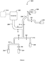
- FIG. 2 illustrates a fire suppression system 200 for distributing a fire suppression mixture.
- Fire suppression system 200 includes container 202 for storing the fire suppression mixture.
- the container 202 may be any type of container designed to hold a fire suppression mixture.
- container 202 is designed to hold the fire suppression mixture under pressure.
- Container 202 is in selective communication with distribution tubing 206, 208, 210 and 212.
- container 202 releases the fire suppressant mixture into tubing 206, 208, 210 and 212.
- Tubing 206, 208, 210 and 212 may be tubing, piping or any other type of structure designed to distribute liquid or gases. The mixture is forced through the tubing and exits the fire suppression system 200 at discharge locations 204.
- the tubing/piping may be made from plastic, rubber, metal, polyvinyl chloride (PVC) or any other type of suitable material.
- PVC polyvinyl chloride
- the material of the tubing should be selected to be inert with respect to the fire suppression mixture it distributes.
- the system 200 delivers the mixture all the way to the discharge locations 204 while maintaining a minimum pressure on the mixture during distribution by maintaining a back pressure.
- the discharge geometry at each distribution location 204 is designed to maintain a positive back pressure above a certain threshold.
- the geometry at the distribution locations 204 restricts flow and maintains the pressure in the system 200 until substantially all the mixture has exited each discharge location 204.
- valves or nozzles may be used to control the geometry at the discharge locations 204 and maintain the minimum pressure throughout the system.
- the exit geometry at the discharge locations 204 may not regulate the pressure but instead the pressure may be regulated by the geometric or physical design of the distribution system itself.
- the tubing or piping 206, 208, 210 and 212 may be designed to maintain a minimum pressure throughout the system 200. For example, by designing the system with the appropriate amount of direction changes and increasing smaller tubing, the mixture may be distributed throughout a fire suppression zone while still maintaining a minimum pressure throughout the system. This may all be achieved without pressure sensitive valves or nozzles at the discharge locations 204.
- the tube 206 that is directly downstream from container 202 has a diameter D.
- the diameter of the tube at each successive downstream branch is smaller i.e., D1 is smaller than D and D2 is smaller than D1 and D3 is smaller than D2.
- the diameter D along with the successive downstream diameters D1-D3 should be selected based on the minimum pressure required to be maintained.
- the number of branches in the overall tube design may also be used to help maintain a minimum pressure. The forced rapid changes in direction may help maintain the pressure upstream from the branch.
- Designing a system that does not require a pressure sensitive valve or nozzle at the discharge point may not only be important for safety reasons, but may also be important for retrofitting capabilities. Most current systems do not use such discharge geometry and therefore, using the geometry of the distribution tubing or piping to maintain a minimum pressure may be advantageous.
- the exit geometry of the discharge locations 204 and the geometry of the tubing may both be designed to help the system 200 maintain a minimum pressure through during operation.
- the tubing diameter and nozzle throat diameter is selected to meet focused concentration, to suppress combustion, and maintain sufficient line pressure to expel liquid phase from the system 200 before a critical low pressure value is reached, approximately 6 atmospheres.
- an additional optional container 214 may be used to hold pressurizing gas.
- Container 214 is in selective communication with container 202 such that as the fire suppressant mixture is expelled from container 202, the pressurizing gas fills the container 202 and prevents the pressure in container 202 from substantially falling. This also helps maintain a minimum pressure throughout the system 200.
- the optional container 214 may not be used.
- an organic fire suppressant with a high normal boiling point such as FK 5-1-12
- an organic compound with a low normal boiling point such as carbon dioxide
- the combination greatly improves the fire suppression properties of either agent separately.
- nitrogen, argon, or helium may be supplemented to increase bottle pressure at low temperatures providing acceptable mass flow at these temperatures.
- the addition of these inert gases also prevents triple point behavior of the CO 2 component during discharge at these low temperatures.
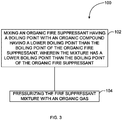
- Fig. 3 illustrates a method of making a fire suppressant mixture for use in a fire suppression system 100.
- an organic fire suppressant is mixed with an organic compound in order to modify a characteristic of the organic fire suppressant.
- the method is used to modify the boiling point of the organic fire suppressant.
- the mixture may be pressurized using an inorganic gas in step 104. It is important to make sure the mixture of the fire suppressant compound and the organic compound is performed before the inorganic gas is introduced, especially if the organic compound is being added to its maximum saturation point or close thereto.
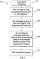
- Fig. 4 illustrates a method of making a fire suppressant mixture that includes a halogen element for use in a fire suppression system 100.
- a container is first evacuated in step 402. Once the container is evacuated, the organic fire suppressant compound may be added in step 404. After the organic fire suppressant compound is added to the container, the halogen element may be mixed or dissolved into the organic fire suppressant compound in step 406. Next, an organic compound with a desirable quality such as a lower boiling point may be mixed into the mixture of organic fire suppressant compound and halogen element. Finally, a pressurizing gas may be added to add additional pressure to the container.
- the method of Fig. 4 describes a method of mixing the fire suppressant material in a container designed for discharge and preferably the components of the fire suppressant mixture are mixed directly in the discharge container.
- the steps 404, 406 and 408 or any subset thereof may occur outside the discharge chamber. Once mixed, the mixture may be added to the discharge chamber and then pressurized in step 410.
Landscapes
- Business, Economics & Management (AREA)
- Emergency Management (AREA)
- Chemical & Material Sciences (AREA)
- Chemical Kinetics & Catalysis (AREA)
- General Chemical & Material Sciences (AREA)
- Health & Medical Sciences (AREA)
- Public Health (AREA)
- Fire-Extinguishing Compositions (AREA)
- Fire-Extinguishing By Fire Departments, And Fire-Extinguishing Equipment And Control Thereof (AREA)
Applications Claiming Priority (3)
| Application Number | Priority Date | Filing Date | Title |
|---|---|---|---|
| US13/423,133 US9034202B2 (en) | 2012-03-16 | 2012-03-16 | Fire suppressing materials and systems and methods of use |
| US13/594,738 US8920668B2 (en) | 2012-03-16 | 2012-08-24 | Fire suppressing materials and systems and methods of use |
| PCT/US2013/032195 WO2014007862A2 (en) | 2012-03-16 | 2013-03-15 | Fire suppressing materials and systems and methods of use |
Publications (3)
| Publication Number | Publication Date |
|---|---|
| EP2825267A2 EP2825267A2 (en) | 2015-01-21 |
| EP2825267A4 EP2825267A4 (en) | 2016-02-24 |
| EP2825267B1 true EP2825267B1 (en) | 2020-09-09 |
Family
ID=49156588
Family Applications (1)
| Application Number | Title | Priority Date | Filing Date |
|---|---|---|---|
| EP13813530.6A Active EP2825267B1 (en) | 2012-03-16 | 2013-03-15 | Fire suppressing materials and systems |
Country Status (9)
| Country | Link |
|---|---|
| US (1) | US8920668B2 (https=) |
| EP (1) | EP2825267B1 (https=) |
| JP (1) | JP6200940B2 (https=) |
| BR (1) | BR112014022988B1 (https=) |
| CA (1) | CA2867531C (https=) |
| ES (1) | ES2835714T3 (https=) |
| IL (1) | IL234594B (https=) |
| RU (1) | RU2678670C2 (https=) |
| WO (1) | WO2014007862A2 (https=) |
Families Citing this family (12)
| Publication number | Priority date | Publication date | Assignee | Title |
|---|---|---|---|---|
| US9713732B2 (en) * | 2012-03-16 | 2017-07-25 | Meggitt Safety Systems, Inc. | Fire suppressing materials and systems and methods of use |
| US9034202B2 (en) * | 2012-03-16 | 2015-05-19 | Meggitt Safety Systems Inc. | Fire suppressing materials and systems and methods of use |
| US8920668B2 (en) * | 2012-03-16 | 2014-12-30 | Meggitt Safety Systems Inc. | Fire suppressing materials and systems and methods of use |
| CN106267672B (zh) * | 2016-08-10 | 2019-11-12 | 九江中船化学科技有限公司 | 一种气体灭火剂组合物及其制备的气体灭火剂 |
| WO2018148354A1 (en) * | 2017-02-09 | 2018-08-16 | Fike Corporation | Silent fire suppression system |
| CN108421204A (zh) * | 2017-02-15 | 2018-08-21 | 上海汇友精密化学品有限公司 | 一种含十二氟-2-甲基-3-戊酮灭火剂组合物 |
| FR3077989B1 (fr) * | 2018-02-20 | 2021-11-19 | Arianegroup Sas | Extincteur d'incendie |
| US10940346B2 (en) * | 2018-05-21 | 2021-03-09 | The Boeing Company | Fire extinguishing system and method therefor |
| WO2021236184A2 (en) | 2020-02-14 | 2021-11-25 | Kidde Technologies, Inc. | Fire suppression blends of cf3i and 2-btp |
| WO2021230935A2 (en) | 2020-02-14 | 2021-11-18 | Kidde Technologies, Inc. | Fire suppression blends of cf3i, hcfos and co2 |
| US11324982B1 (en) * | 2020-10-19 | 2022-05-10 | Kidde Technologies, Inc. | Fire suppression compositions |
| US12614768B2 (en) | 2022-12-17 | 2026-04-28 | Kidde Technologies Inc. | Battery outgassing detector |
Family Cites Families (33)
| Publication number | Priority date | Publication date | Assignee | Title |
|---|---|---|---|---|
| US4226728A (en) * | 1978-05-16 | 1980-10-07 | Kung Shin H | Fire extinguisher and fire extinguishing composition |
| JPS63240884A (ja) * | 1987-03-30 | 1988-10-06 | 株式会社東芝 | 消火設備 |
| SU1563712A1 (ru) * | 1988-04-29 | 1990-05-15 | Предприятие П/Я Р-6453 | Огнетушитель |
| GB8903334D0 (en) * | 1989-02-14 | 1989-04-05 | Ici Plc | Flame extinguishing compositions |
| US5759430A (en) * | 1991-11-27 | 1998-06-02 | Tapscott; Robert E. | Clean, tropodegradable agents with low ozone depletion and global warming potentials to protect against fires and explosions |
| SE523661C2 (sv) * | 1992-02-05 | 2004-05-04 | American Pacific Corp | Gas-vätskeblandning avsedd för användning som brandsläckningsmedel |
| US5611210A (en) * | 1993-03-05 | 1997-03-18 | Ikon Corporation | Fluoroiodocarbon blends as CFC and halon replacements |
| US5626786A (en) * | 1995-04-17 | 1997-05-06 | Huntington; John H. | Labile bromine fire suppressants |
| GB9812083D0 (en) * | 1998-06-05 | 1998-08-05 | Ici Plc | Removal of water |
| US6478979B1 (en) * | 1999-07-20 | 2002-11-12 | 3M Innovative Properties Company | Use of fluorinated ketones in fire extinguishing compositions |
| US6346203B1 (en) * | 2000-02-15 | 2002-02-12 | Pcbu Services, Inc. | Method for the suppression of fire |
| US6315219B1 (en) | 2000-10-20 | 2001-11-13 | Nathan Palestrant | Misting-system fluid-atomization manifold |
| GB2370768A (en) * | 2001-01-09 | 2002-07-10 | Kidde Plc | Fire and explosion suppression |
| DE60216244T2 (de) * | 2001-03-29 | 2007-05-10 | Kidde IP Holdings Ltd., Colnbrook, Slough | Mittel zum feuerlöschen und zur explosionsunterdrückung |
| US7223351B2 (en) * | 2003-04-17 | 2007-05-29 | Great Lakes Chemical Corporation | Fire extinguishing mixtures, methods and systems |
| US7454910B2 (en) * | 2003-06-23 | 2008-11-25 | Denso Corporation | Waste heat recovery system of heat source, with Rankine cycle |
| RU2006107555A (ru) | 2003-08-11 | 2006-07-27 | Е.И.Дюпон де Немур энд Компани (US) | Способы применения фторсульфонов для пожаротушения, предотвращения возгорания и уменьшения или устранения воспламеняемости воспламеняющейся рабочей жидкости |
| US20050145820A1 (en) * | 2004-01-06 | 2005-07-07 | Waldrop Stephanie D. | Compositions and methods useful for synergistic combustion suppression |
| US7465698B2 (en) * | 2004-04-16 | 2008-12-16 | Honeywell International Inc. | Azeotrope-like compositions of difluoromethane and trifluoroiodomethane |
| US7094356B2 (en) * | 2004-05-26 | 2006-08-22 | E. I. Dupont Denemours And Company | 1,1,1,2,2,4,5,5,5-nonafluoro-4-(trifluoromethyl)-3-pentanone refrigerant compositions and uses thereof |
| CA2591669C (en) * | 2005-01-12 | 2013-03-19 | Eclipse Aviation Corporation | Fire suppression systems |
| US7569170B2 (en) * | 2005-03-04 | 2009-08-04 | E.I. Du Pont De Nemours And Company | Compositions comprising a fluoroolefin |
| DE102006048015B4 (de) * | 2006-10-09 | 2015-01-29 | Minimax Gmbh & Co. Kg | Feuerlöschanlage für ein Gehäuse |
| JP4966793B2 (ja) * | 2007-09-10 | 2012-07-04 | 能美防災株式会社 | 消火設備 |
| US8846754B2 (en) * | 2009-12-16 | 2014-09-30 | Honeywell International Inc. | Azeotrope-like compositions of cis-1,1,1,4,4,4-hexafluoro-2-butene |
| US8096366B2 (en) | 2010-12-10 | 2012-01-17 | American Pacific Corporation | Environmentally beneficial and effective hydrochlorofluorocarbon compositions for fire extinguishing applications |
| WO2013028152A1 (en) * | 2011-08-19 | 2013-02-28 | Utc Fire & Security Corporation | System and method of conditioning and delivery of liquid fire extinguishing agent |
| US9463341B2 (en) | 2011-10-25 | 2016-10-11 | Kidde Technologies, Inc. | N2/CO2 fire extinguishing system propellant gas mixture |
| US9192798B2 (en) * | 2011-10-25 | 2015-11-24 | Kidde Technologies, Inc. | Automatic fire extinguishing system with gaseous and dry powder fire suppression agents |
| ES2685512T3 (es) * | 2011-11-18 | 2018-10-09 | Minimax Gmbh & Co. Kg | Instalación para la extinción o inertización con un agente de extinción sintético líquido |
| EP2617467A1 (en) * | 2012-01-20 | 2013-07-24 | Kidde Technologies, Inc. | Multiple discharge fire extinguishing system |
| US8920668B2 (en) * | 2012-03-16 | 2014-12-30 | Meggitt Safety Systems Inc. | Fire suppressing materials and systems and methods of use |
| US9034202B2 (en) * | 2012-03-16 | 2015-05-19 | Meggitt Safety Systems Inc. | Fire suppressing materials and systems and methods of use |
-
2012
- 2012-08-24 US US13/594,738 patent/US8920668B2/en active Active
-
2013
- 2013-03-15 ES ES13813530T patent/ES2835714T3/es active Active
- 2013-03-15 WO PCT/US2013/032195 patent/WO2014007862A2/en not_active Ceased
- 2013-03-15 EP EP13813530.6A patent/EP2825267B1/en active Active
- 2013-03-15 RU RU2014141678A patent/RU2678670C2/ru active
- 2013-03-15 JP JP2015500659A patent/JP6200940B2/ja active Active
- 2013-03-15 CA CA2867531A patent/CA2867531C/en active Active
- 2013-03-15 BR BR112014022988-0A patent/BR112014022988B1/pt active IP Right Grant
-
2014
- 2014-09-11 IL IL234594A patent/IL234594B/en active IP Right Grant
Non-Patent Citations (1)
| Title |
|---|
| None * |
Also Published As
| Publication number | Publication date |
|---|---|
| IL234594B (en) | 2018-07-31 |
| WO2014007862A3 (en) | 2014-03-06 |
| JP2015517833A (ja) | 2015-06-25 |
| BR112014022988B1 (pt) | 2021-06-29 |
| RU2014141678A (ru) | 2016-05-10 |
| CA2867531C (en) | 2021-05-25 |
| EP2825267A2 (en) | 2015-01-21 |
| EP2825267A4 (en) | 2016-02-24 |
| ES2835714T3 (es) | 2021-06-23 |
| US20130240217A1 (en) | 2013-09-19 |
| US8920668B2 (en) | 2014-12-30 |
| RU2678670C2 (ru) | 2019-01-30 |
| BR112014022988A2 (pt) | 2017-06-20 |
| JP6200940B2 (ja) | 2017-09-20 |
| CA2867531A1 (en) | 2014-01-09 |
| WO2014007862A2 (en) | 2014-01-09 |
Similar Documents
| Publication | Publication Date | Title |
|---|---|---|
| EP2825267B1 (en) | Fire suppressing materials and systems | |
| US9713732B2 (en) | Fire suppressing materials and systems and methods of use | |
| US9034202B2 (en) | Fire suppressing materials and systems and methods of use | |
| ES2629033T3 (es) | Composiciones de extinción de incendios y supresión de incendios que comprenden fluorocarbonos insaturados | |
| KR101746161B1 (ko) | 환경적으로 유익하고 효과적인 소화용 하이드로클로로플루오로카본 조성물 | |
| JP3558629B2 (ja) | 消火方法および携帯用消火器 | |
| EP3621703B1 (en) | Fire extinguishing compositions and methods | |
| US20180318623A1 (en) | Hfo-1224yd fire extinguishing compositions, systems and methods | |
| JPH06509492A (ja) | 気−液混合物、その使用装置及び使用方法 | |
| AU771605B2 (en) | Method for the suppression of fire | |
| CN103269755A (zh) | 作为灭火组合物的氟化环氧化物以及使用其灭火的方法 | |
| AU2103995A (en) | Ozone friendly fire extinguishing methods and compositions | |
| CN117695580A (zh) | 一种含氟气体灭火剂组合物 | |
| WO2015048604A1 (en) | Fire extinguishing and fire suppression compositions comprising 3-chloro-1,1,1-trifluoropropene | |
| CN112190866A (zh) | 一种六氟丙烷混合灭火剂及其制备方法 | |
| AU2015218556B2 (en) | Fire extinguishing and fire suppression compositions comprising unsaturated fluorocarbons | |
| CA2449614C (en) | Fire extinguishing composition and process | |
| OZONE | bromine or chlorine is present, no damage occurs. Fluorine does not damage ozone since it reacts rapidly with methane and other materials to form HF, which is stable and is eventually lost by migration to the troposphere |
Legal Events
| Date | Code | Title | Description |
|---|---|---|---|
| PUAI | Public reference made under article 153(3) epc to a published international application that has entered the european phase |
Free format text: ORIGINAL CODE: 0009012 |
|
| 17P | Request for examination filed |
Effective date: 20141013 |
|
| AK | Designated contracting states |
Kind code of ref document: A2 Designated state(s): AL AT BE BG CH CY CZ DE DK EE ES FI FR GB GR HR HU IE IS IT LI LT LU LV MC MK MT NL NO PL PT RO RS SE SI SK SM TR |
|
| AX | Request for extension of the european patent |
Extension state: BA ME |
|
| DAX | Request for extension of the european patent (deleted) | ||
| A4 | Supplementary search report drawn up and despatched |
Effective date: 20160125 |
|
| RIC1 | Information provided on ipc code assigned before grant |
Ipc: A62D 1/08 20060101AFI20160119BHEP |
|
| STAA | Information on the status of an ep patent application or granted ep patent |
Free format text: STATUS: EXAMINATION IS IN PROGRESS |
|
| 17Q | First examination report despatched |
Effective date: 20180515 |
|
| REG | Reference to a national code |
Ref country code: DE Ref legal event code: R079 Ref document number: 602013072428 Country of ref document: DE Free format text: PREVIOUS MAIN CLASS: A62D0001080000 Ipc: A62D0001000000 |
|
| GRAP | Despatch of communication of intention to grant a patent |
Free format text: ORIGINAL CODE: EPIDOSNIGR1 |
|
| STAA | Information on the status of an ep patent application or granted ep patent |
Free format text: STATUS: GRANT OF PATENT IS INTENDED |
|
| RIC1 | Information provided on ipc code assigned before grant |
Ipc: A62D 1/00 20060101AFI20200311BHEP |
|
| INTG | Intention to grant announced |
Effective date: 20200330 |
|
| GRAS | Grant fee paid |
Free format text: ORIGINAL CODE: EPIDOSNIGR3 |
|
| GRAA | (expected) grant |
Free format text: ORIGINAL CODE: 0009210 |
|
| STAA | Information on the status of an ep patent application or granted ep patent |
Free format text: STATUS: THE PATENT HAS BEEN GRANTED |
|
| AK | Designated contracting states |
Kind code of ref document: B1 Designated state(s): AL AT BE BG CH CY CZ DE DK EE ES FI FR GB GR HR HU IE IS IT LI LT LU LV MC MK MT NL NO PL PT RO RS SE SI SK SM TR |
|
| REG | Reference to a national code |
Ref country code: GB Ref legal event code: FG4D |
|
| REG | Reference to a national code |
Ref country code: AT Ref legal event code: REF Ref document number: 1310821 Country of ref document: AT Kind code of ref document: T Effective date: 20200915 Ref country code: CH Ref legal event code: EP |
|
| REG | Reference to a national code |
Ref country code: IE Ref legal event code: FG4D |
|
| REG | Reference to a national code |
Ref country code: DE Ref legal event code: R096 Ref document number: 602013072428 Country of ref document: DE |
|
| REG | Reference to a national code |
Ref country code: LT Ref legal event code: MG4D |
|
| PG25 | Lapsed in a contracting state [announced via postgrant information from national office to epo] |
Ref country code: NO Free format text: LAPSE BECAUSE OF FAILURE TO SUBMIT A TRANSLATION OF THE DESCRIPTION OR TO PAY THE FEE WITHIN THE PRESCRIBED TIME-LIMIT Effective date: 20201209 Ref country code: BG Free format text: LAPSE BECAUSE OF FAILURE TO SUBMIT A TRANSLATION OF THE DESCRIPTION OR TO PAY THE FEE WITHIN THE PRESCRIBED TIME-LIMIT Effective date: 20201209 Ref country code: HR Free format text: LAPSE BECAUSE OF FAILURE TO SUBMIT A TRANSLATION OF THE DESCRIPTION OR TO PAY THE FEE WITHIN THE PRESCRIBED TIME-LIMIT Effective date: 20200909 Ref country code: GR Free format text: LAPSE BECAUSE OF FAILURE TO SUBMIT A TRANSLATION OF THE DESCRIPTION OR TO PAY THE FEE WITHIN THE PRESCRIBED TIME-LIMIT Effective date: 20201210 Ref country code: LT Free format text: LAPSE BECAUSE OF FAILURE TO SUBMIT A TRANSLATION OF THE DESCRIPTION OR TO PAY THE FEE WITHIN THE PRESCRIBED TIME-LIMIT Effective date: 20200909 Ref country code: FI Free format text: LAPSE BECAUSE OF FAILURE TO SUBMIT A TRANSLATION OF THE DESCRIPTION OR TO PAY THE FEE WITHIN THE PRESCRIBED TIME-LIMIT Effective date: 20200909 Ref country code: SE Free format text: LAPSE BECAUSE OF FAILURE TO SUBMIT A TRANSLATION OF THE DESCRIPTION OR TO PAY THE FEE WITHIN THE PRESCRIBED TIME-LIMIT Effective date: 20200909 |
|
| REG | Reference to a national code |
Ref country code: AT Ref legal event code: MK05 Ref document number: 1310821 Country of ref document: AT Kind code of ref document: T Effective date: 20200909 |
|
| REG | Reference to a national code |
Ref country code: NL Ref legal event code: MP Effective date: 20200909 |
|
| PG25 | Lapsed in a contracting state [announced via postgrant information from national office to epo] |
Ref country code: LV Free format text: LAPSE BECAUSE OF FAILURE TO SUBMIT A TRANSLATION OF THE DESCRIPTION OR TO PAY THE FEE WITHIN THE PRESCRIBED TIME-LIMIT Effective date: 20200909 Ref country code: PL Free format text: LAPSE BECAUSE OF FAILURE TO SUBMIT A TRANSLATION OF THE DESCRIPTION OR TO PAY THE FEE WITHIN THE PRESCRIBED TIME-LIMIT Effective date: 20200909 Ref country code: RS Free format text: LAPSE BECAUSE OF FAILURE TO SUBMIT A TRANSLATION OF THE DESCRIPTION OR TO PAY THE FEE WITHIN THE PRESCRIBED TIME-LIMIT Effective date: 20200909 |
|
| PG25 | Lapsed in a contracting state [announced via postgrant information from national office to epo] |
Ref country code: CZ Free format text: LAPSE BECAUSE OF FAILURE TO SUBMIT A TRANSLATION OF THE DESCRIPTION OR TO PAY THE FEE WITHIN THE PRESCRIBED TIME-LIMIT Effective date: 20200909 Ref country code: EE Free format text: LAPSE BECAUSE OF FAILURE TO SUBMIT A TRANSLATION OF THE DESCRIPTION OR TO PAY THE FEE WITHIN THE PRESCRIBED TIME-LIMIT Effective date: 20200909 Ref country code: SM Free format text: LAPSE BECAUSE OF FAILURE TO SUBMIT A TRANSLATION OF THE DESCRIPTION OR TO PAY THE FEE WITHIN THE PRESCRIBED TIME-LIMIT Effective date: 20200909 Ref country code: RO Free format text: LAPSE BECAUSE OF FAILURE TO SUBMIT A TRANSLATION OF THE DESCRIPTION OR TO PAY THE FEE WITHIN THE PRESCRIBED TIME-LIMIT Effective date: 20200909 Ref country code: NL Free format text: LAPSE BECAUSE OF FAILURE TO SUBMIT A TRANSLATION OF THE DESCRIPTION OR TO PAY THE FEE WITHIN THE PRESCRIBED TIME-LIMIT Effective date: 20200909 Ref country code: PT Free format text: LAPSE BECAUSE OF FAILURE TO SUBMIT A TRANSLATION OF THE DESCRIPTION OR TO PAY THE FEE WITHIN THE PRESCRIBED TIME-LIMIT Effective date: 20210111 |
|
| PG25 | Lapsed in a contracting state [announced via postgrant information from national office to epo] |
Ref country code: AL Free format text: LAPSE BECAUSE OF FAILURE TO SUBMIT A TRANSLATION OF THE DESCRIPTION OR TO PAY THE FEE WITHIN THE PRESCRIBED TIME-LIMIT Effective date: 20200909 Ref country code: AT Free format text: LAPSE BECAUSE OF FAILURE TO SUBMIT A TRANSLATION OF THE DESCRIPTION OR TO PAY THE FEE WITHIN THE PRESCRIBED TIME-LIMIT Effective date: 20200909 Ref country code: IS Free format text: LAPSE BECAUSE OF FAILURE TO SUBMIT A TRANSLATION OF THE DESCRIPTION OR TO PAY THE FEE WITHIN THE PRESCRIBED TIME-LIMIT Effective date: 20210109 |
|
| REG | Reference to a national code |
Ref country code: DE Ref legal event code: R097 Ref document number: 602013072428 Country of ref document: DE |
|
| REG | Reference to a national code |
Ref country code: ES Ref legal event code: FG2A Ref document number: 2835714 Country of ref document: ES Kind code of ref document: T3 Effective date: 20210623 |
|
| PG25 | Lapsed in a contracting state [announced via postgrant information from national office to epo] |
Ref country code: SK Free format text: LAPSE BECAUSE OF FAILURE TO SUBMIT A TRANSLATION OF THE DESCRIPTION OR TO PAY THE FEE WITHIN THE PRESCRIBED TIME-LIMIT Effective date: 20200909 |
|
| PLBE | No opposition filed within time limit |
Free format text: ORIGINAL CODE: 0009261 |
|
| STAA | Information on the status of an ep patent application or granted ep patent |
Free format text: STATUS: NO OPPOSITION FILED WITHIN TIME LIMIT |
|
| 26N | No opposition filed |
Effective date: 20210610 |
|
| PG25 | Lapsed in a contracting state [announced via postgrant information from national office to epo] |
Ref country code: DK Free format text: LAPSE BECAUSE OF FAILURE TO SUBMIT A TRANSLATION OF THE DESCRIPTION OR TO PAY THE FEE WITHIN THE PRESCRIBED TIME-LIMIT Effective date: 20200909 Ref country code: SI Free format text: LAPSE BECAUSE OF FAILURE TO SUBMIT A TRANSLATION OF THE DESCRIPTION OR TO PAY THE FEE WITHIN THE PRESCRIBED TIME-LIMIT Effective date: 20200909 |
|
| PG25 | Lapsed in a contracting state [announced via postgrant information from national office to epo] |
Ref country code: MC Free format text: LAPSE BECAUSE OF FAILURE TO SUBMIT A TRANSLATION OF THE DESCRIPTION OR TO PAY THE FEE WITHIN THE PRESCRIBED TIME-LIMIT Effective date: 20200909 |
|
| REG | Reference to a national code |
Ref country code: CH Ref legal event code: PL |
|
| GBPC | Gb: european patent ceased through non-payment of renewal fee |
Effective date: 20210315 |
|
| REG | Reference to a national code |
Ref country code: BE Ref legal event code: MM Effective date: 20210331 |
|
| PG25 | Lapsed in a contracting state [announced via postgrant information from national office to epo] |
Ref country code: IE Free format text: LAPSE BECAUSE OF NON-PAYMENT OF DUE FEES Effective date: 20210315 Ref country code: GB Free format text: LAPSE BECAUSE OF NON-PAYMENT OF DUE FEES Effective date: 20210315 Ref country code: LI Free format text: LAPSE BECAUSE OF NON-PAYMENT OF DUE FEES Effective date: 20210331 Ref country code: LU Free format text: LAPSE BECAUSE OF NON-PAYMENT OF DUE FEES Effective date: 20210315 Ref country code: CH Free format text: LAPSE BECAUSE OF NON-PAYMENT OF DUE FEES Effective date: 20210331 |
|
| PG25 | Lapsed in a contracting state [announced via postgrant information from national office to epo] |
Ref country code: BE Free format text: LAPSE BECAUSE OF NON-PAYMENT OF DUE FEES Effective date: 20210331 |
|
| PG25 | Lapsed in a contracting state [announced via postgrant information from national office to epo] |
Ref country code: HU Free format text: LAPSE BECAUSE OF FAILURE TO SUBMIT A TRANSLATION OF THE DESCRIPTION OR TO PAY THE FEE WITHIN THE PRESCRIBED TIME-LIMIT; INVALID AB INITIO Effective date: 20130315 |
|
| PG25 | Lapsed in a contracting state [announced via postgrant information from national office to epo] |
Ref country code: CY Free format text: LAPSE BECAUSE OF FAILURE TO SUBMIT A TRANSLATION OF THE DESCRIPTION OR TO PAY THE FEE WITHIN THE PRESCRIBED TIME-LIMIT Effective date: 20200909 |
|
| PG25 | Lapsed in a contracting state [announced via postgrant information from national office to epo] |
Ref country code: MK Free format text: LAPSE BECAUSE OF FAILURE TO SUBMIT A TRANSLATION OF THE DESCRIPTION OR TO PAY THE FEE WITHIN THE PRESCRIBED TIME-LIMIT Effective date: 20200909 |
|
| PG25 | Lapsed in a contracting state [announced via postgrant information from national office to epo] |
Ref country code: TR Free format text: LAPSE BECAUSE OF FAILURE TO SUBMIT A TRANSLATION OF THE DESCRIPTION OR TO PAY THE FEE WITHIN THE PRESCRIBED TIME-LIMIT Effective date: 20200909 |
|
| PG25 | Lapsed in a contracting state [announced via postgrant information from national office to epo] |
Ref country code: MT Free format text: LAPSE BECAUSE OF FAILURE TO SUBMIT A TRANSLATION OF THE DESCRIPTION OR TO PAY THE FEE WITHIN THE PRESCRIBED TIME-LIMIT Effective date: 20200909 |
|
| PGFP | Annual fee paid to national office [announced via postgrant information from national office to epo] |
Ref country code: ES Payment date: 20250401 Year of fee payment: 13 |
|
| PGFP | Annual fee paid to national office [announced via postgrant information from national office to epo] |
Ref country code: DE Payment date: 20260327 Year of fee payment: 14 |
|
| PGFP | Annual fee paid to national office [announced via postgrant information from national office to epo] |
Ref country code: IT Payment date: 20260319 Year of fee payment: 14 |
|
| PGFP | Annual fee paid to national office [announced via postgrant information from national office to epo] |
Ref country code: FR Payment date: 20260325 Year of fee payment: 14 |