EP2825146B1 - Active orthosis for the motion neurological rehabilitation of lower limbs, system comprising such orthosis and process for operating such system - Google Patents
Active orthosis for the motion neurological rehabilitation of lower limbs, system comprising such orthosis and process for operating such system Download PDFInfo
- Publication number
- EP2825146B1 EP2825146B1 EP13715459.7A EP13715459A EP2825146B1 EP 2825146 B1 EP2825146 B1 EP 2825146B1 EP 13715459 A EP13715459 A EP 13715459A EP 2825146 B1 EP2825146 B1 EP 2825146B1
- Authority
- EP
- European Patent Office
- Prior art keywords
- supporting
- patient
- orthosis
- handling
- supporting means
- Prior art date
- Legal status (The legal status is an assumption and is not a legal conclusion. Google has not performed a legal analysis and makes no representation as to the accuracy of the status listed.)
- Active
Links
- 230000033001 locomotion Effects 0.000 title claims description 70
- 210000003141 lower extremity Anatomy 0.000 title claims description 32
- 230000000926 neurological effect Effects 0.000 title claims description 10
- 238000000034 method Methods 0.000 title description 14
- 230000008569 process Effects 0.000 title description 7
- 210000000689 upper leg Anatomy 0.000 claims description 49
- 210000002303 tibia Anatomy 0.000 claims description 38
- 210000002414 leg Anatomy 0.000 claims description 37
- 210000003423 ankle Anatomy 0.000 claims description 29
- 210000001624 hip Anatomy 0.000 claims description 28
- 210000002683 foot Anatomy 0.000 claims description 21
- 210000004197 pelvis Anatomy 0.000 claims description 16
- 230000004913 activation Effects 0.000 claims description 15
- 229910000831 Steel Inorganic materials 0.000 claims description 14
- 210000003127 knee Anatomy 0.000 claims description 14
- 239000010959 steel Substances 0.000 claims description 14
- 239000000463 material Substances 0.000 claims description 11
- 230000002829 reductive effect Effects 0.000 claims description 8
- 230000009471 action Effects 0.000 claims description 6
- 239000003638 chemical reducing agent Substances 0.000 claims description 4
- 230000003993 interaction Effects 0.000 claims description 4
- 230000008859 change Effects 0.000 claims description 3
- 238000004092 self-diagnosis Methods 0.000 claims description 2
- 238000013519 translation Methods 0.000 claims description 2
- 230000036961 partial effect Effects 0.000 description 16
- 230000005021 gait Effects 0.000 description 15
- 238000001994 activation Methods 0.000 description 14
- 239000000725 suspension Substances 0.000 description 11
- 238000011282 treatment Methods 0.000 description 9
- 210000003414 extremity Anatomy 0.000 description 8
- 230000007170 pathology Effects 0.000 description 8
- 125000006850 spacer group Chemical group 0.000 description 7
- 210000003205 muscle Anatomy 0.000 description 6
- 230000001225 therapeutic effect Effects 0.000 description 6
- 238000002560 therapeutic procedure Methods 0.000 description 6
- 239000004677 Nylon Substances 0.000 description 5
- 230000006399 behavior Effects 0.000 description 5
- 230000037396 body weight Effects 0.000 description 5
- 230000000694 effects Effects 0.000 description 5
- 229920001778 nylon Polymers 0.000 description 5
- 238000011156 evaluation Methods 0.000 description 4
- 238000002599 functional magnetic resonance imaging Methods 0.000 description 4
- 210000001503 joint Anatomy 0.000 description 4
- 230000037230 mobility Effects 0.000 description 4
- 239000004753 textile Substances 0.000 description 4
- 229920001780 ECTFE Polymers 0.000 description 3
- 239000004411 aluminium Substances 0.000 description 3
- 229910052782 aluminium Inorganic materials 0.000 description 3
- XAGFODPZIPBFFR-UHFFFAOYSA-N aluminium Chemical compound [Al] XAGFODPZIPBFFR-UHFFFAOYSA-N 0.000 description 3
- 230000008901 benefit Effects 0.000 description 3
- 210000004556 brain Anatomy 0.000 description 3
- 238000006243 chemical reaction Methods 0.000 description 3
- 238000010276 construction Methods 0.000 description 3
- 230000006872 improvement Effects 0.000 description 3
- 238000012549 training Methods 0.000 description 3
- 206010019468 Hemiplegia Diseases 0.000 description 2
- 208000032843 Hemorrhage Diseases 0.000 description 2
- 208000007542 Paresis Diseases 0.000 description 2
- 230000008878 coupling Effects 0.000 description 2
- 238000010168 coupling process Methods 0.000 description 2
- 238000005859 coupling reaction Methods 0.000 description 2
- 238000010586 diagram Methods 0.000 description 2
- 206010019465 hemiparesis Diseases 0.000 description 2
- 210000004394 hip joint Anatomy 0.000 description 2
- 230000002452 interceptive effect Effects 0.000 description 2
- 208000028867 ischemia Diseases 0.000 description 2
- 210000000629 knee joint Anatomy 0.000 description 2
- 230000003902 lesion Effects 0.000 description 2
- 238000012423 maintenance Methods 0.000 description 2
- 229910052751 metal Inorganic materials 0.000 description 2
- 239000002184 metal Substances 0.000 description 2
- 238000012544 monitoring process Methods 0.000 description 2
- 230000008447 perception Effects 0.000 description 2
- 239000004033 plastic Substances 0.000 description 2
- 238000011084 recovery Methods 0.000 description 2
- 210000000278 spinal cord Anatomy 0.000 description 2
- 230000001133 acceleration Effects 0.000 description 1
- 230000003213 activating effect Effects 0.000 description 1
- 230000006978 adaptation Effects 0.000 description 1
- 230000003044 adaptive effect Effects 0.000 description 1
- 230000000712 assembly Effects 0.000 description 1
- 238000000429 assembly Methods 0.000 description 1
- 230000000903 blocking effect Effects 0.000 description 1
- 244000309466 calf Species 0.000 description 1
- 230000002860 competitive effect Effects 0.000 description 1
- 238000011109 contamination Methods 0.000 description 1
- 238000001816 cooling Methods 0.000 description 1
- 230000003412 degenerative effect Effects 0.000 description 1
- 230000001419 dependent effect Effects 0.000 description 1
- 238000007599 discharging Methods 0.000 description 1
- 238000006073 displacement reaction Methods 0.000 description 1
- 239000003814 drug Substances 0.000 description 1
- 239000012530 fluid Substances 0.000 description 1
- 230000006870 function Effects 0.000 description 1
- 208000014674 injury Diseases 0.000 description 1
- 230000000670 limiting effect Effects 0.000 description 1
- 230000007246 mechanism Effects 0.000 description 1
- 238000012986 modification Methods 0.000 description 1
- 230000004048 modification Effects 0.000 description 1
- 230000005405 multipole Effects 0.000 description 1
- 230000004118 muscle contraction Effects 0.000 description 1
- 230000008555 neuronal activation Effects 0.000 description 1
- 238000011017 operating method Methods 0.000 description 1
- 230000010355 oscillation Effects 0.000 description 1
- 230000000737 periodic effect Effects 0.000 description 1
- 230000003252 repetitive effect Effects 0.000 description 1
- 238000011160 research Methods 0.000 description 1
- 230000004044 response Effects 0.000 description 1
- 238000001228 spectrum Methods 0.000 description 1
- 238000012360 testing method Methods 0.000 description 1
- 239000012815 thermoplastic material Substances 0.000 description 1
- 230000008733 trauma Effects 0.000 description 1
- 230000002618 waking effect Effects 0.000 description 1
Images


Classifications
-
- A—HUMAN NECESSITIES
- A61—MEDICAL OR VETERINARY SCIENCE; HYGIENE
- A61H—PHYSICAL THERAPY APPARATUS, e.g. DEVICES FOR LOCATING OR STIMULATING REFLEX POINTS IN THE BODY; ARTIFICIAL RESPIRATION; MASSAGE; BATHING DEVICES FOR SPECIAL THERAPEUTIC OR HYGIENIC PURPOSES OR SPECIFIC PARTS OF THE BODY
- A61H3/00—Appliances for aiding patients or disabled persons to walk about
- A61H3/008—Using suspension devices for supporting the body in an upright walking or standing position, e.g. harnesses
Landscapes
- Health & Medical Sciences (AREA)
- Epidemiology (AREA)
- Pain & Pain Management (AREA)
- Physical Education & Sports Medicine (AREA)
- Rehabilitation Therapy (AREA)
- Life Sciences & Earth Sciences (AREA)
- Animal Behavior & Ethology (AREA)
- General Health & Medical Sciences (AREA)
- Public Health (AREA)
- Veterinary Medicine (AREA)
- Rehabilitation Tools (AREA)
- Acyclic And Carbocyclic Compounds In Medicinal Compositions (AREA)
Description
- The present invention refers to an active orthosis for the motion neurological rehabilitation of lower limbs, to a system comprising such orthosis and to a process for operating such system.
- The prior art in the field of active exoskeletons used in motion rehabilitation of lower limbs in general has only machines with fixed station, with exoskeleton constrained thereto. They are in general rather rigid and heavy machines, that block some physiologic motions of the human walk and that allow treatments in general only on treadmill, with patient in general only with partial weight discharge. In almost no cases there is the ankle activation, and even less the chance of activating it in the same machine. The collected examples are sometimes also inadequate to control the actual man-machine interaction, with consequent generation of dynamic actions that cannot absolutely be controlled. Very often the patient has many difficulties in wearing the exoskeleton, thing that impair the correct and easy use of the system. The found example, moreover, have, with respect to the invention as described below, a strong lack of versatility in accommodating different pathologies and clinic protocols of various natures with a single system.
- As known prior art, the following patents have been deemed pertinent, but not relevant, for the present invention:
-
US-B-6,666,831 "Method, apparatus and system for automation of body weight support training (BWST) of biped locomotion over a treadmill using a programmable stepper device (PSD) operating like an exoskeleton drive system from a fixed base", December 2003
Such patent refers to a rehabilitation system with fixed station using only the treadmill, and to an exoskeleton directly integrated with the fixed structure. It is based on external robotic arms, with telescopic and rotation movements, linked to the frame. There are also acceleration, force and torque sensors. A special shoe is used, equipped with sensors, to monitor the contact with the ground. The movement is imposed only on the sagittal plane, in a rigid way.
The system according to the present invention, with respect to the one in this patent, allows treating a wider spectrum of pathologies with different therapeutic cases, not being compulsorily linked to a fixed station and having an exoskeleton that has been more recently and originally conceived. -
US-A-2004/0116839 "Gait training apparatus", June 2004
This patent shows a fixed rehabilitation station with a very simple exoskeleton constrained to the fixed frame. This requires, among other things, a not very easy procedure to be worn on the patient. There are rotations of hip, knee and ankle, however obtained with a single linear motor, instead of two actuators connected in an acting/counteracting way, like the system according to the present invention.
Differently from this latter one, the system of documentUS-A-2004/0116839 has a rather complex system for anthropometrical adjustments, with linear motors and adjusting mechanisms, which makes the physiotherapist work more complex and longer. Moreover, the system stiffness can produce forces on the patient's legs, while the use of linear actuators for adjusting femur and tibia segments does not guarantee the position, unless a mechanical brake is applied onto the cylinder. It is therefore a globally very complex and heavy structure, differently from the system according to the present invention. -
US-A-0143198 "Powered gait orthosis and method of utilizing same", July 2004
This patent has a fixed rehabilitation station with exoskeleton constrained to the fixed structure. No modes are allowed for various types of walks, apart the one on treadmill with partial weight discharge. No motions are allowed outside the sagittal plane, thereby making a much more limited and rigid structure than the system according to the present invention. There is no ankle activation. -
US-B-7,041,069 "Improved powered gait orthosis and method of utilizing same", May 2006
This patent, evolution of the previous one, has a fixed rehabilitation station with exoskeleton constrained to the fixed structure. No modes are allowed for various types of walks, apart the one on treadmill with partial weight discharge. No motions are allowed outside the sagittal plane, thereby making a much more limited, heavy and rigid structure than the system according to the present invention. There is no ankle activation. It is not easy to wear the patient. -
US-B-7,125,388 "Robotic gait rehabilitation by optimal motion of the hip", October 2006
This patent has a fixed rehabilitation station with actuators, constrained to the base, that impose the motion to the patient pelvis. The system is used both to reactivate such motion and possibly for monitoring it. The patient arms are free and there is no actual driving exoskeleton. The system is based on the use of a treadmill, with patient always in suspension. Its conception and structure are very different from the system according to the present invention -
US-B-7,190,141 "Exoskeleton device for rehabilitation", March 2007
At first sight, this patent seems to show a system similar to the one according to the present invention, but deep differences appear immediately evident. The exoskeleton has no ankle activation and seems more suitable for walking on place, instead of a trend of various rehabilitation protocols. It is focused on the concept of two-feet robot, forgetting the man-machine interaction, which can be foreseen with difficulty even by a sophisticated control system, especially for dynamic contributions. In this case, the patient is treated, therefore, as an inter object, without reaction capabilities. The system according to the present invention, instead, derives from the chance of exerting on the patient various motion therapies, all comprising the effect of a personal contribution. Such effect is better pointed out, by lowering the working pressure of the exoskeleton, and thereby studying the autonomous walking capabilities of the examined patient. -
US-A-2007/0056592 "Semi-powered lower extremity exoskeleton", March 2007
This patent has a walk-helping device, more than an actual rehabilitation exoskeleton. The system is semi-active, with the only activation of the knee joint. Conception and objects are different with respect to the system according to the present invention. -
US-B-7,33,906 "Apparatus and method for repetitive motion therapy", February 2008
This patent has a fixed rehabilitation station with actuators, constrained to the base, and a treadmill. The actuators are fixed to the patient's legs, to which they impose a motion to be coordinated also with the treadmill speed, according to a scarcely physiological logic and with balance problem for the patient. There is no actuation on the ankle articulation, nor of various types of walk, unless with partial weight discharge through BWS. The exoskeleton has a different conception with respect to the system according to the present invention and is moreover stiffer and less versatile. -
US-A-0255488 "Powered orthosis", October 2008
This patent has a fixed rehabilitation station with actuators, constrained to the base, and a treadmill. There is no actuation on the ankle articulation, The control system is complex and cumbersome, more typical of a robotic structure than of a rehabilitation exoskeleton, requiring suitable sensors and periodic calibrations. A strong maintenance action is thereby required, differently from the system according to the present invention. The motion is allowed only on the sagittal plane. Not using the principle of the acting/counteracting muscle, the structure requires more encumbrant and heavier actuators, taking to a rigid and scarcely versatile system, in addition to having strong friction actions. The exoskeleton has a different conception with respect to the system according to the present invention. -
US-A-0071442 "Robot for walk training and operating method thereof", March 2011
The patent has a rehabilitation system with fixed station with exoskeleton constrained to the structure and to the patient on treadmill, with partial weight discharge through BWS, single possible treatment mode, differently from the versatility characteristic of the system according to the present invention. There is no actuation on the ankle articulation. The patent contains more a summarily description of a possible rehabilitation method than a presentation of an original machine. It is a system with a different conception with respect to the system according to the present invention. -
US-B-7,947,004 "Lower extremity exoskeleton", May 2011
The patent is a revision ofUS-A1-2007/0056592 . It is anyway referred to a walk-helping device, more than an actual rehabilitation exoskeleton. The system is semi-active with the single activation of the knee joint. It has different conception and objects from the system according to the present invention. -
- Therefore, object of the present invention is solving the above prior art problems, by providing an active orthosis for motion neurological rehabilitation of the lower limbs, that allows treating clinical problems such as hemiplegia, tetraparesis, hemiparesis, comprising ictus, ischemia, brain haemorrhage, partial lesions of the spinal cord, with extension, in some cases, to muscle dystrophy and to motion degenerative pathologies. Such active orthosis is further useful in exercises and studies for motor learning that can also be applied on healthy individuals. The above described orthosis does not need the use of a treadmill, has a relatively simple, light-weight, compact, cheap and flexible construction, which can be easily controlled and used also by users with various types of motion difficulties.
- The versatility of the active orthosis of the invention allows it anyway to possibly work both in a traditional way, namely in suspension, and on the ground, with patient motion in a room and partial weight discharge.
- A further object of the present invention is providing a system comprising the above described orthosis, that, in addition to the advantages of the orthosis as described above, is equipped with a plurality of operating, maintenance, diagnostic and analysis functionalities, that make its application open to several solutions in the diagnostic, therapeutic, rehabilitation and research fields, both in medicine and in neurology.
- Another object of the present invention is providing a process for operating the above described system.
- The above and other objects and advantages of the invention, as will appear from the following description, are obtained with a orthosis like the one claimed in
claim 1, a system equipped with such orthosis and a process for operating such system, as claimed in their respective claims. Preferred embodiments and non-trivial variations of the present invention are the subject matter of the dependent claims. - It is intended that all enclosed claims are an integral part of the present description.
- The present invention will be better described by some preferred embodiments thereof, provided as a non-limiting example, with reference to the enclosed drawings, in which:
-
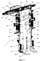
Figure 1 is a perspective view of a preferred embodiment of the orthosis of the present invention; -
Figure 2 is a schematic view of the main components of the inventive system; -
Figure 3 is a view similar toFigure 1 , that shows only a part of the inventive orthosis for a leg; -
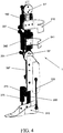
Figure 4 is a side perspective view ofFigure 3 ; -
Figure 5 is a side view ofFigure 3 ; -
Figure 6 is a side perspective view ofFigure 3 , seen on the opposite side with respect toFigure 4 ; -
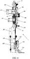
Figure 7 is a partial perspective view of the inventive orthosis in its part applied to the legs and in a movement position; -
Figure 8 is a perspective detailed view of a possible embodiment of the handle of the inventive system; -
Figure 9 is a detailed perspective view of a further embodiment of the handle of the inventive system; -
Figure 10 is an exploded perspective view of the handle ofFigure 9 ; -
Figure 11 is a detailed perspective view of the handle ofFigure 9 ; -
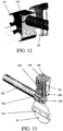
Figure 12 is a perspective view of a part of the handle ofFigure 9 ; -
Figure 13 is a perspective view of the connection between handle, corset and hip joint; -
Figure 14 is an exploded perspective view of a possible embodiment of the joint for the hip articulation; -
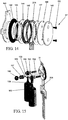
Figure 15 is a perspective view of the external part of the joint for the hip articulation; -
Figure 16 is a perspective view of the placement of the pneumatic cylinders on the hip joint and of the ball knot at the end of the cylinder stem; -
Figures 17 to 19 are three side views of three possible operating positions of hip moving cylinders; -
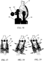
Figure 20 is an exploded perspective view of the assembly of the hip moving cylinders; -
Figure 21 is a perspective view of the hip moving cylinders in their assembling position; -
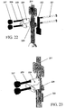
Figure 22 is a perspective view to show the relative motion between femur slider and its guide; -
Figure 23 is a perspective view of a detail ofFigure 22 ; -
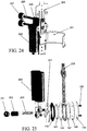
Figure 24 is a perspective detailed view ofFigure 22 , from the opposite side with respect toFigure 23 and with assembled cylinders; -
Figure 25 is an exploded perspective view of the knee articulation joint; -
Figure 26 is an exploded perspective view of the orthosis part applied to calf and femur; -
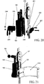
Figure 27 is a perspective view of the lower part of the orthosis with the ankle-moving cylinder; -
Figure 28 is a view showing the rest configuration with the femur segment aligned with the tibia segment; -
Figure 29 is a view showing the flexing conditions of the tibia segment ofFigure 28 with respect to the femur segment; -
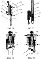
Figure 30 is an exploded perspective view of the ankle articulating joint; -
Figure 31 is a side perspective view of the lower part of the inventive orthosis to be applied to the left leg of a patient; -
Figure 32 shows three side operating positions of the ankle movement obtained through the inventive orthosis; -
Figure 33 is an exploded perspective view of the lower part of the inventive orthosis for moving the ankle; -
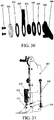
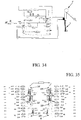
Figure 34 is a schematic diagram of a preferred configuration of the ground box of the inventive system; -
Figure 35 is a preferred electro-pneumatic diagram of the inventive system; -
Figure 36 is a graph showing the angular behaviour of the hip articulation referred to the right leg (curve with solid line) and the left leg (dashed curve); and -
Figures 37 to 39 are side schematic views of possible operating positions of the inventive orthosis. - With reference to the Figures, some preferred embodiments of the orthosis, the system and the process according to the present invention are shown and described. It will be immediately obvious that numerous variations and modifications (for example related to shape, sizes, arrangements and parts with equivalent functionality) could be made to what is described, without departing from the scope of the present invention, as appears in the enclosed claims.
- The invention deals, first of all, with an
active orthosis 1, preferably with electro-pneumatic drive, for the motion neurological rehabilitation of the lower limbs, whereinsuch orthosis 1 is equipped with at least four, and preferably six degrees of freedom for the movement respectively of the two hips, of the two knees and optionally of the two ankles of a patient 1'. - The invention further deals with a
system 3 for the motion neurological rehabilitation of lower limbs that therefore substantially comprises: at least oneactive orthosis 1 of the above mentioned type; at least onecontrol box 5; and at least one computer (preferably a personal computer) 28 to acquire and process data, and manage the sitting by an operator. - Going on now to describe in detail the subject matter of the present invention, it has also been called "P.I.G.R.O." (Pneumatic Interactive Gait Rehabilitation Orthosis) and it is a bio-mechanical device with at least four, and preferably six, degrees of freedom, aimed to the robotized neurological rehabilitation of lower limbs in patients lacking mobility for cranial traumas, ictus or other.
- From a first global perspective of the system according to the present invention, two important features can be distinguished. The first one is the movement of the ankle, a very important articulation very relevant in the walking process, even if normally not present in other devices, and the second one is the chance of performing different rehabilitation cycles in suspension or on the ground without treadmill. The gait cycle is performed with the patient 1' initially lifted from the ground through a winch (Body Weight Support or BWS) .
-
Figure 2 shows all necessary elements for operating thesystem 3 according to the present invention. It is composed of aorthosis 1, adapted to support the patient 1' and actuated by pneumatic actuators controlled by solenoid valves, that contains, in the rear part of the structure, a control andinterface box 22, with at least onesupply duct 23 for compressed air and at least oneelectric connection cable 25, and aground managing system 5, equipped with adequate means and with at least one computing machine. The compressed air supply comes from acompressor 24 withcable 29 or from a distribution network. In case of asingle duct 23, there is a single supply for the two legs; in case of many ducts, the supply can be separate for the two legs or according to the different pneumatic actuators. Inside theinterface box 22, there are also possible control cards, connected to electronic interface drivers placed in acontrol box 26 also containing acquisition cards, through a serial cable or a fire wire or Ethernet or a wireless system. With them, feedback and commands are exchanged for the solenoid valves and the electric supplies between orthosis andground managing system 5. The real time control can be made with commercial components assembled according to an innovative logic, that provides for one or more control cards on board theorthosis 1 in thebox 22 and one or more cards in thecontrol box 26. This allows using asingle PC 28 of a traditional type connected to thecontrol box 26 with acable 27. It contains a control software, that can be used by a user through a suitable graphic interface. The PC is single, but is normally equipped with two monitors: themonitor 31 is dedicated to operator's needs, while themonitor 32 is the system biofeedback, useful both for the operator, and for the patient, for a self-diagnosis action during the rehabilitation sitting. - As regards structure and actuators, the system is composed of a modular exoskeleton with six degrees of freedom with actuation of the hip, knee and ankle articulations, with movement chances mainly in the sagittal plane. The supply system allows moving two independent "legs" through actuators placed in acting-counteracting position, preferably of the pneumatic type, fastened to the structure, that guarantee a safe movement since they avoid forcing situations towards the patient 1' in case of muscle contraction, reduced costs, simple managing and controlling architecture.
- For operating the
inventive system 3, a distribution network for compressed air is necessary, generally present in all hospitals, in which thesystem 3 will preferably operate. With the use of pneumatic actuators, preferred in the embodiment, the use of electric wires is avoided, together with all those safety problems associated therewith, and this is a more adaptive system to possible reactions produced by the patient. The use of hydraulics actuators is less suitable, since contamination is not allowed in the medical environments due to possible fluid leakages from the system, and anyway they would not be particularly advantageous in terms of controllability. - The two legs are joined at the pelvis height through a
read handle 92 that can be adjusted in its width, that prevents their relative rotation and allows placing abox 22 containing the valve assembly for supply and the pneumatic cylinders exhaust, a distribution plate for compressed air and the control card to which input and output signals are connected betweenorthosis 1 andground managing system 5. - In case of separate supply of compressed air to the two legs, the distribution plate contains two supply channels that connect the inputs of the valves controlling the right or left leg, separately. There are therefore two pressure reducers in the
control box 26, to have the chance of independently adjusting the pressure in the two legs. Therefore, there are two supply tubes betweencontrol box 26 andbox 22. Outputs of all exhaust valves are instead conveyed inside thebox 22, allowing to attenuate noise and local cooling. The supply valves are digital, normally closed 2/2 solenoid valves, controlled by a Pulse Width Modulation, PWM system, that allows obtaining a flow-rate with variable behaviour when the cycle changes. In order to take care of extreme situations, and therefore allow movement freedom to the patient that is dressed with theorthosis 1, when he enters in an emergency situation, the exhaust valves are of the normally open 2/2 type. In this way,, in an emergency, the actuators are getting exhausted and the patient, though still dressing theorthosis 1, is free of moving the lower limbs according to current needs. For every cylinder chamber, one or more normally closed solenoid valves for supply, and one or more normally open solenoid valves for exhaust can be used. - As regards the geometry of the inventive system, both the legs, and the rear handle are made through means, composed for example of elements that are able to slide one over the others, with possible locking in the desired position, in order to change the length of the femur and tibia segments depending on the anthropometrical sizes of the patient 1'. The possible adjustments determine:
- A - pelvis width
- B - femur length
- C - tibia length
- The anthropometrical sizes depend on several factors, among which sex, age and geographic provenience.
- In order to guarantee a certain pelvis mobility, even outside the sagittal plane, the adjustable devices (blades and sliders) of the orthosis legs comprise elements (blades) made of harmonic steel. This allows a good suitability to different anatomic shapes of different patients, and possible pelvis motions even on the front plane.
- The interface with the patient 1' occurs with a corset, that can be opened to insert the patient and can be closed with fastening elements, that can be made of plastic or semi-rigid material with textile solutions, and fastened to the rear handle. In the version made of plastic material, the corset is equipped on the front part with many hinges, of the same number on each side, to allow its opening and enable the patient 1' to easily wear it. After that, the corset will be tightened to the waist of the patient 1', allowing him to keep an erect position. In order to be correctly adapted to the bust shape, many corsets are provided, for example for men and women, and/or with different sizes. It is also provided to use a semi-rigid corset with textile base.
- In order to fasten the lower limbs to the structure, "showers" are provided, the showers being an orthopaedic term used to designate a channel obtained to contain and immobilize a limb. Characteristic of these showers is being open to allow inserting the limb and comprising means for locking the limb. The number of showers, their shape and their type of closure can change according to the embodiments. In an embodiment, here provided for, there are two showers at the thigh height, one shower for the tibia segment and finally another shower for the foot. The showers can be made of elastic steel or thermoplastic material. In order to close the showers, Velcro™-type strips can be used, that perform a partial adaptation to the physical features of the patient 1', or textile structures that can be closed.
- As regards the articulation control system, the control architecture of the system according to the present invention is with closed loop.
- As input, curves related to gait cycle are provided, obtained from literature and suitably modified, according to medical indications, being the rehabilitation in suspension and reactions with the ground being therefore null, or for other therapeutic purposes.
- These curves are continuously compared with the feedbacks coming from potentiometers or other position transducers, placed in parallel with one of the cylinders for every articulation, in order to detect the behaviour of the real cycle performed by the exoskeleton. If the patient 1' contrasts the movement, the potentiometer of the articulation subjected to efforts will give a reduced movement signal with respect to the curve set as input; vice versa if the orthosis overlaps the patient 1'. The difference between the two, real and reference, signals produces an error that is processed by the software controlling the orthosis, sending suitable output signals to the actuating system of the solenoid valves (PWM).
- As regard the control type, various types of controllers can be used, both of the PID (Proportional Integral Derivative) type, and of the Fuzzy type or others.
- The PWM modifies the cycle amplitude following an error, and controls the related solenoid valves for actuating the pneumatic cylinders. In any cylinder chamber, there are also pressure transducers, necessary for evaluating the pressure behaviours therein and therefore the developed force, useful in some diagnostic steps.
- The rehabilitation steps with the system according to the present invention provide, for the severest patients 1', a suspension path as described above, where the patient 1' is totally guided by the exoskeleton. In the following steps, always however in suspension, it is possible to increase the working load, reducing the pressure supplied to the pneumatic actuators, so that the user actively contributes to the movement. If required by the therapy, it is also possible to remove the ankle articulation, since the tibia segment is sliding and adapted to be detached from the remaining assembly. The patient 1' will then be able to walk on the ground, with partial weight discharge, and with hip and knee articulations always actuated by the system according to the present invention. The absence of a treadmill allows a more physiological walking with more perception of the movement in the surrounding environment, and it is possible, by changing the input curves, to move along different paths. In all cases, it will be possible to display the working sitting on a screen, in which reference curves are represented together with the feedback coming from the potentiometers.
- At any time the patient 1' will be able to compare, with his therapist, his own movement with the ideal one (biofeedback monitor).
- Herein below the main components of the
inventive orthosis 1 will be described. - As regards the limbs, the reference limb for building the first leg is the right side, and reference will be made only to this side, since the left side is a mirror image thereof.
Figure 3 , seen from outside, shows the final result, and the following can be distinguished, starting from the top and going downwards: joint 31' for hip articulation, femur segment 32', knee articulation 33',tibia segment 34 and ankle join 35. - As regards the hip articulation, as can be seen in
Figure 14 , the joint 31' is composed of several elements, designed as to minimize frictions and encumbrances. It is composed of anexternal element 141 fastened through the two holes, placed in the upper part, to therear handle 92, that prevents it from rotating. In the internal part, it is equipped with a hub, on which abush 142 will be keyed-in, and a series of element alternating with wear-preventingrings component 201 is the femur slider hinge, parallel to the human limb, and is the one on which thepneumatic cylinders 160 will be placed, that rotate it with respect to the joint 31'. In order to reduce the components to a minimum, joints for hip 31' andknee 33 have been made very similar. In order to compensate the distances, abush 145 is placed in the hip and serves exclusively as shim. Finally, aplate 148 and a smallinternal plate 149 are placed, that allow closing the joint 31' with twoscrews 150 with flared head. -
Figure 15 shows the external side of the element 31', in which there are two threaded holes, symmetrical with respect to the vertical, suitable to position twopins 152 necessary for placing thestems 159 of thecylinders 160. The end of the stems 159 is threaded, allowing their fastening to standard ball joints 154, to have a rotation and oscillation movement lacking friction and without play. The axial constraint is guaranteed on one side by abush 153, and on the other side by aSeeger ring 155 placed in a suitable groove obtained on thepin 152. On the rotation axis of the hip articulation, a threadedpin 156 is placed, fastened to the element 31', and necessary as support for a protection carter, placed betweenspacer 157 andknob 158. The protection carter is wound around the whole exoskeleton, allowing the operator to adjust the distances between the joints, exclusively operating on the knobs without interacting with the actuation and control systems of thesystem 3 according to the present invention. -
Figure 16 shows a global view pertaining to the placement of thepneumatic cylinders 160 on the joint 31' of the hip (on the left) and the ball joint at the end of the stem of the cylinder 160 (on the right). - The
pneumatic cylinders 160 are constrained at their lower end by exploiting the presence of holes that are diametrically opposite to the surface of thecylinder 160 chamber (Figure 20 ). Assembling consists in inserting a suitablyshaped pin 206 inside the seat of thefemur slider 201 on one side, and inside theliner 202 of thecylinder 160 on the other side. Thepin 206 axially constrains thecylinder 160, but must allow a rotation related to thepin 206 itself. Afterwards, asecond pin 205, geometrically identical to theprevious pin 206, is placed on the opposite side of thecylinder 160 and, after having repeated the same operations also for theother cylinder 160, a connectingbracket 203 is placed, fastened to thefemur slider 201 with a system with screw 207 - self-lockingnut 204. Function of thelower screw 207 is also placing anylon spacer 208 necessary for fastening athigh shower 210 through riveting (Figure 21 ). The central hole placed on the shower allows passing the screw suitable for fastening the assembly to the femur blade. - In order to actuate the hip, there are two
pneumatic cylinders 160 with connection with crossed chamber, that operate in an acting-counteracting way. While the first actuator produces a frontward thrusting force, the second exerts a backwards force, allowing a rotation of thefemur slider 201 with respect to the joint fastened to therear handle 92. This configuration allows a smaller encumbrance with respect to asingle cylinder 160 with greater bore and the thrusting surface is equal to the sum of the greater surface and the smaller surface. - The stroke of the
cylinders 160 is sized depending on the limit angular excursion of the articulation, set by the physiological gait, and the compliance with these constraints is mechanically guaranteed when at least one plunger of the twocylinders 160 is at the end of its stroke. -
Figures 17, 18 and 19 respectively show the configuration at rest, the extension step and the flexion step. Not knowing the actual internal sizes of thecylinders 160, modelling therein is only qualitative. Arrows A designate the supply to thecylinders 160, whole arrows B the exhaust. - As regards the femur segment, to allow the femur segment to be adjustable depending on the patient 1' features, the femur slider 201 (also called femur blade) is made slide inside a
femur guide 228. The femur blade orslider 201 is made of harmonic steel, which allows the structure to flex also outside the sagittal plane, giving the patient 1' a less rigid movement, while for the guide, having bigger sizes, aluminium has been employed to assign a certain lightness thereto. To avoid seizure problems, a third element is interposed, fastened to the guide, and made of turcite, which guarantees low friction, reduced wear and long life. The relative motion betweenfemur slider 201 and its guide is shown inFigure 22 . - Locking of the femur segment in a certain position occurs by friction, namely by tightening the various components through a
knob 227. Thenylon spacer 222 ofFigure 22 , necessary for fastening athigh shower 210, is equipped with two square breakings, as well as the guide, suitable to house twoscrews 221, with crowned head and square sub-head, preventing their rotation. At the opposite end, abracket 224 is placed in contact with thefemur slider 201 and axially constrained by Seeger rings 225. Finally, acovering ring 226 is inserted outside the screw, obtaining the configuration shown inFigure 23 . By tightening theknob 227, the elements included betweenscrew 221 head andbracket 224 are packaged, preventing their sliding. The presence of Seeger rings is necessary since, should theknob 227 be wrongly removed, thescrews 221 would remain assembled, preventing the system from being decomposed. - In the femur blade there is a slit which allows it to slide without interfering with the tightening screws, and which prevents its disassembling. The screws further provide a limit switch for the adjustment size ends included between 10%ile for women and 95%ile for men. Both on the
femur guide 228 and on thebracket 224, two holes are obtained for placing thepneumatic cylinders 242 necessary for actuating the knee articulation. The arrangement is similar to the one described for the hip (Figure 24 ), as well as fastening asecond thigh shower 241 onto the spacer with riveting. - The knee articulation is different with respect to the hip articulation only due to two components that are shown in
Figure 25 . More precisely, thefemur guide 228 replaces thefemur slider 201 and thepart 145 ofFigure 14 , and theexternal element 254 replaces the previous one (part 141 ofFigure 14 ) operating as guide also for the tibia segment. Theelement 254 is equipped with two holes for placing pins that support the stems of thecylinders 242, arranged rotated by 30° with respect to a plane perpendicular to the vertical, to allow only a 60° flexure allowed for the knee articulation. There is also anadjustment knob 251 withrelated support 252 connected to anadjustment rod 253. - The two
pneumatic cylinders 242 have connections with crossed chambers and operate in an acting-counteracting way.Figure 28 and Figure 29 show the rest configuration (Figure 28 ) with the femur segment aligned with the tibia segment, and the flexure condition (Figure 29 ). Arrows C designate the supply ofcylinders 242, while arrows D designate the exhaust. - The tibia segment (
Figure 26 ) is simpler with respect to the femur segment, and is composed of thealuminium guide 261 on which anelement 262 made of turcite is overlapped with a similar geometry of its seat. Thetibia blade 265 made of harmonic steel is placed thereon, and is able to slide if adjustments of the tibia length must be made. The relative sliding between the two elements is blocked by friction with the screw-nut screw type tightening. Twoscrews 269 are provided, with crowned head and square sub-head, that also allow fastening the tibia shower to the guide, by interposing asuitable spacer 266 and using twoknobs 264. To guarantee a better fastening between tibia blade and its guide, also thescrew 268 withknow 263 is inserted. - Since in subsequent rehabilitation steps, it is provided that a patient 1' walks on the ground, it has been necessary to provide for the removal of the tibia segment and the related ankle articulation. For such purpose, an upward-opened groove is made on the tibia blade, which allows avoiding an interference with the screws and its easy removal.
- In the lower part of the tibia blade, as shown in
Figure 27 , there are two holes adapted to fasten asupport 273 of thepneumatic cylinder 275 for moving the ankle articulation. In this case, a single actuator is used, having reduced sizes with respect to the previous ones, both because the loads to be supported are lower, and due to encumbrance problems. The actuator is supported by abracket 273, fastened to thetibia blade 265 withscrews 274 with cylindrical head and hexagonal recess and related nut, and is placed in the front part of the structure, differently fromprevious cylinders 275 that are laterally placed. The actuator is fastened to the bracket by means of two diametrically opposite screws 272. - The ankle articulation (
Figure 30 ) is composed of analuminium plate 308 that is the foot flank, and on whose front end apin 309 will be fastened for keying-in thecylinder 275 stem. Theelement 308 is equipped with a hub, on which a friction-preventingring 305 is placed, which, in turn, supports the tibia blade 304, ashim element 306 and, at the two ends, a friction-preventingring external plate 302 and twoscrews 301 with flared head. - In the internal part of the foot flank bracket, the
shower 310 is fastened for positioning thepatient 1's foot. As shown inFigures 31 and32 , twospacers 312 with different thickness are arranged, to then place theshower 310 fastened to the structure with twoscrews 311 with crowned head and square sub-head, and nut. This type of screw avoids its rotation and is not uncomfortable for the patient 1'. In the opposite part, a threadedpin 313 is placed for housing the ball joint together with the stem of thecylinder 275. The axial displacement is prevented by a Seeger ring. - The angular excursion of the ankle has been increased with respect to the one of the physiological walk upon medical request, for reasons linked to waking in suspension.
-
Figure 32 shows, from left to right, the rest configuration, the plantar flexure and the dorsal flexure steps. Arrows E designate the cylinders supply while arrows F designate the exhaust. - From the first experimentation steps on healthy patients, it has been discovered that the body weight of the patient 1', abutting partly onto the foot shower, generated a downward flexure thereof on its internal leg side.
- In order to solve the problem, it has been necessary to use supplementary support means, such as a connecting rod between foot shower and tibia shower (
Figure 33 ). - It is composed of a system with screw 337 -
nut screw 335 that allows the length adjustment, and at whose ends a ball joint 333, 338 is connected, to avoid making the structure hyper-static and to reduce overall sizes to a minimum. They are keyed-in on twopins first nut nut nut 334, withdraw the joint 333 from thepin 331, move away thenut 336 operating as stopper, unscrew or screw, depending on needs, the system with screw 337 -nut screw 335, take back thenut 336 against the nut screw and insert again the joint 333 with thenut 336. - As regards the
rear handle 92, it can be built according to various embodiments, a first one of which is shown inFigure 8 . The handle is composed of twoforks 81 placed at its ends, which allow fastening the exoskeleton at the height of the hip articulation. The pelvis width can be adjusted (manually or through an electric or pneumatic motor) by sliding two concentrictubular elements element 84 and a pin fastened inside the structure on a plate, prevents the relative rotation between the two elements. - The rectilinear section above the
knob 83 is used for fastening thebox 22 containing the valve assembly and the distribution plate for compressed air. As regard fastening with a limb, inside thefork 81 the small external plate 31' is placed, for the hip articulation, and a plate (not shown) necessary for fastening thecorset 210; everything is tightened with two through-screws with unscrewing-preventing nuts. Thecorset 210 is fastened to the structure by three screws, with their head oriented towards its internal part, and with self-locking nuts at the opposite end. A nylon spacer is also inserted, that allows coupling the curved shape of thecorset 210 with the plane bracket surface. - According to a preferred embodiment, the
rear handle 92, as shown inFigures 9 to 12 , first of all comprises two handles 91.Figure 9 shows a global view of this element. In order to adapt it to a greater number of patients, a minimum adjusting distance is imposed, equal to 300 mm, with a maximum distance of 650 mm. It is composed of a suitable shapedcentral block 112, inside which anelectric motor 94 and areducer 95 are placed. The rotation motion is transmitted to a worm screw with double slant through a toothed belt, or a pair of toothed wheels.Figure 11 schematically shows the kinematism withmotor 94,reducer 95 andworm screw 96. - At the ends of the central block, two bearings are placed for keying-in therein the
worm screw 96, together with other two bearings, placed at the ends of theworm screw 96 and constrained onplates 103 for closing thehandle 92. In both cases, these are radial bearings, respectively designated with 101 and 102 inFigure 10 . Between the twoend plates 103, twoguides small plates 104 are externally placed as protection. - Depending on the rotation direction of the motor, and therefore of the worm screw, a translation is generated for two small nut screw blocks, on which the legs will be placed, when going near and away one from the other, by changing the pelvis length depending on the features of the patient 1' (
Figure 11 ). The twosmall blocks 101, in addition to be coupled with the worm screw 113 (96), are kept in position by the twoguides -
Figure 12 shows more in detail the small block with the presence of fourbushings 121, two on each part, for housing the guides, while in the front part, atubular segment 123 is placed, fastened through two bitingscrews 122 with cylindrical head. A slit is obtained in the small block to make it easier to insert the cylindrical outline, while the screws allow approaching the two small block edges, generating a tightening. - In order to guarantee a correct motor stop with small nut screw block at the end of its stroke, two limit switches have been placed in the end heads, which stop the motor when their minimum or maximum opening is reached.
-
Figure 13 shows a series of elements that are connected at the opposite end of thetubular segment 123. The first one of them is thefork 132, inside which the smallexternal plate 133 of the hip articulation 31' is placed, and from which the whole leg departs, and abracket 134. Everything is tightened by two screws with flared head and self-locking nuts 139. Afemale dovetail 135 is fastened to thebracket 134 with other two screws with flared head andnuts 137, while inside it the respectivemale dovetail 136 is made slide with a suitably slanted surface, since it will have to follow the curved geometry of thecorset 210 supporting it. - The
element 136 is supported in the lower part by aplate 138 fastened to the female dovetail with three biting screws. - With this system, it is possible to adjust the position of the
corset 210 depending on the anthropometrical sizes of the patient 1', making the male dovetail slide in its respective seat, and constraining it through a locking system placed on one side of the female dovetail. - Laterally to the structure, two handles will be placed, suitable for lifting and moving the
exoskeleton 1, while in the rear part, through two brackets, thebox 22 will be placed, that contains the valve assembly, the distribution plate for compressed air and the control cards. - Joining the
rear handle 92 with the two legs, the result shown inFigure 1 is obtained. - In order to allow a gait cycle in suspension, it is necessary to lift the system according to the present invention through a hook placed on the
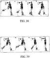
tubular segment 123 of therear handle 92. - The photograms of a gait cycle are shown in
Figures 37 to 39 . - Summarising, the
active orthosis 1 of the present invention is used for the motion neurological rehabilitation of lower limbs, and it is equipped with at least four, and preferably six, degrees of freedom for a movement respectively of the two hips, of the two knees and optionally of the two ankles of a patient 1' without having to use supporting and handling treadmills; theorthosis 1 comprising: - an elongated supporting
structure 92; - a first supporting and
handling structure - a second supporting and
handling structure - a third supporting and
handling structure handling structure orthosis 1; - According to the invention, the elongated supporting
structure 92 is so rigid as to allow the first, second and third supporting and handlingstructures structure 92 being also adjustable to be suited to sizes of the patient 1' when the patient 1' wears and uses theorthosis 1. - Moreover, the
orthosis 1 is adapted to be used both in a suspended condition, and in a condition where the weight of the patient 1' is partially supported, and on the ground. - In particular, in order to obtain the above object, in the
inventive orthosis 1, the first supporting andhandling structure structure 92 through at least one first junction element 31'; the first supporting means 201 are made of a flexible material along a plane passing through the axis of the first junction element 31', the first handling means (160) being of the acting/counteracting type and allowing a handling of the femur exclusively in the sagittal plane. - Still in particular, in order to obtain the above object, in the
inventive orthosis 1, the second supporting andhandling structure - Also in particular, in order to obtain the above object, in the
inventive orthosis 1, the third supporting andhandling structure means 310 for abutting and supporting the foot through at least onethird junction element 35; and the fourth supporting means 265 are made of a flexible material along a plane passing through the axis of the second junction element 33', the third handling means 275 being of the acting/counteracting type and allowing a handling of the foot exclusively in the sagittal plane, the fourth supporting means 265 being adapted to be operatively connected to and disconnected from the third supporting means 261. - In this arrangement, in order to obtain described effects, the first supporting means 201 and the fourth supporting means 265 can be sliders made of plates of harmonic steel, while the second supporting means 228 and the third supporting means 261 can be metallic guides.
- Always in particular, in order to obtain the above object, in the
inventive orthosis 1, the first supporting andhandling structure structure 92 through at least one first junction element 31'; the first supporting means 201 are of the acting/counteracting type and allow a handling of the femur exclusively in the sagittal plane. - Also in particular, in order to obtain the above object, in the
inventive orthosis 1, the second supporting andhandling structure - Finally, also in particular, in order to obtain the above object, in the
inventive orthosis 1, the third supporting andhandling structure means 310 for abutting and supporting the foot through at least onethird junction element 35, the third handling means 275 being of the acting/counteracting type and allowing a handling of the foot exclusively in the sagittal plane, the fourth supporting means 265 being adapted to be operatively connected to and disconnected from the third supporting means 261. - In this arrangement, in order to obtain the described effects, the first supporting means 201 and the fourth supporting means 265 can be metallic guides, while the second supporting means 228 and the third supporting means 261 can be sliders made of plates of harmonic steel.
- The first and the second handling means 160, 242 are preferably composed, on every lower limb, of pairs of pneumatic cylinders with crossed chambers and the third handling means 275 are composed, on any lower limb, preferably of a pneumatic cylinder, or the first, second and third handling means 160, 242, 275 can be composed of electric or hydraulic actuators.
- In addition to the two example configuration described above, obviously, other combinations are possible, in which, for example, the first supporting means 201 and the third supporting means 261 are sliders made of harmonic steel plates, and the second supporting means 228 and the fourth supporting means 265 are metallic guides; or in which the second supporting means 228 and the fourth supporting means 265 are sliders made of harmonic steel plates, and the first supporting means 201 and the third supporting means 261 are metallic guides.
- It can therefore be seen from above that the
orthosis 1 of the invention, in its preferred embodiment, is composed of five main groups: the first group is composed of the supportingstructure 92 and the first supporting andhandling structure handling structure handling structure - The
active orthosis 1 consists in a modular supporting structure, with four or six degrees of freedom, adjustable, for example, from the 10%ile of women to the 95%ile of men, according to the anthropometrical sizes of the patient 1', preferably with a pneumatic actuation (the actuation could also be electric or hydraulic), closed into suitable safety carters and constrained to the basic structure. - It is in turn composed of modules aimed for pelvis, femur segment and tibia segment, mutually connected by low-friction joints and by harmonic steel plates.
- In this way, an original system (alternatively also called machine herein below) has been obtained, not only able to be adapted to different physiological shapes, but above all a machine that allows, when walking on the ground, a certain pelvis mobility even outside the sagittal plane. In this way, the path imposed to the patient 1' during his therapeutic sitting is more natural and the treatment efficiency improves.
- There is, in the system according to the present invention, an activation both on the hip articulation, and on the knee articulation, and on the ankle articulation, peculiarity of the system. In fact, the system according to the present invention can be made operate both in suspension, and on the ground, with partial or total discharge, or not, of the weight of the patient 1', according to therapeutic needs. During both treatments, it is very important to activate the tibia-tarsus articulation, since it allows major neuronal activations for a complete recovery of the patient 1'. In both cases, it is provided to use a Body Weight Support (BWS) able to always discharge the
orthosis 1 weight, in addition to the patient 1' weight, if required. - It must be stated that the ankle activation in the examined
orthosis 1 can also be removed, leaving the patient 1' free of autonomously moving his foot when walking on the ground, if this is required. - Walking on the ground, moreover, has been preferred to the one that can be obtained with a fixed station with the use of a treadmill, since the advancement inside a space provides the patient 1' with feelings and perceptions of a different nature, very important for the various rehabilitation steps; in any case, if required, it is anyway possible to use a treadmill.
- The pelvis width, equipped with a
corset 210 constrained to the back of the patient 1' due to fastening Velcro™ bands, can be modified due to the sliding and automatedrear handle 92 to which thecorset 210 is fastened. Purpose of thehandle 92 is also keeping joined the two legs of theorthosis 1, making it easier for the patient 1' to wear it. - Along femur and tibia segments, whose length can be adjusted due to a prismatic coupling, the interface with the patient 1' is obtained through thigh members and showers closed with Velcro™ bands or textile elements.
- The femur and tibia actuating assemblies consists in pairs of pneumatic cylinders with crossed chambers, that operate by simulating the principle of an acting and counteracting muscle, not pointed out in other patents. Such assembly allows using two actuators with smaller sizes with respect to solutions with a single motor. The cylinders of the system according to the present invention are fastened on the slider part that s integral with the articulation, and are covered by protecting carters in order to close every moving part: from these, only the knobs project that are necessary for the anthropometrical adjustment.
- Every leg of the
orthosis 1 is equipped with pressure sensors for detecting the pressure in the cylinder chambers and with position sensors, to detect the motion of the various articulations and use it as feedback in the control that manages the system. - The
orthosis 1 is then equipped with acontrol box 22, placed behind the patient back, where the control solenoid valves and the electronic cards are placed, that are able to perform, on board the machine, a real time check, sending acquired data to a PC through a wire for transmitting coded signals, or with multi-pole cables or with wireless connections. - The Range Of Movement (ROM) has been increased on purpose, in case of the ankle, with respect to the physiological movements, to increase the activation of motion circuits of the patient 1'. The system ROMs according to the present invention are included in Table 1, not exclusively.
Table 1: ROMs for the various articulations of the system according to the present invention Articulation Max extension [°] Max flexure [°] R.O.M. [°] Hip 20 20 40 Knee 0 60 60 Ankle 25 15 40 - The anthropometrical adjustments allowed in the examined
orthosis 1 are wide and are included in Table 2, not exclusively.Table 2: Anthropometrical adjustments allowed in the system according to the present invention 10%ile woman [mm] 95%ile man [mm] Adjustment Range [mm] Pelvis length 300 650 350 Femur length 370 500 130 Tibia length 360 500 140 - The
ground managing system 5 comprises: at least one card for managing the orthosis - PC connections; an electro-pneumatic control circuit; emergency systems: a preferred embodiment of such components is shown inFigure 34 . - As regards emergencies, there are three types in the system: an emergency for the patient 1', that therefore, if able, can stop the sitting in case of need; a manual emergency and an emergency from software for the operator. All these actions force to go out of the software and to start again the sitting, saving it or not.
- A peculiarity of the system is then the presence, in the
control box 26, of two electronic pressure regulators, which allow independently adjusting from software, the pressure in the legs of theorthosis 1. This innovative aspect is extremely useful in case of treatments of hemiplegia, tetraparesis, hemiparesis, since it could be necessary to apply different activation forces to the two legs. - The pressure regulation in the actuators further allows changing the force that the
orthosis 1 exerts on the legs of the patient 1' , thereby varying the man-machine interaction, since the more the pressure is reduced, the more the thrust to the legs lowers and the patient 1' must demonstrate to be able to autonomously work. - This allows various evaluations about the motion learning status and the rehabilitation improvements thereof, evaluated during the sitting through the biofeedback present in the system.
- The
computer 28 instead comprises the managing software and is connected to two monitors. - Of the two monitors, one is dedicated to the operator, the other one to the biofeedback. In this case, therefore, the input curves with the patient response are displayed and compared in real time on the monitor, for every articulation.
- The managing software, instead, allows controlling in position the imposed motion, using as input the behaviours (physiological or not, even asymmetrical on the two legs, according to needs) of the angles of the various articulations, depending on the gait cycle, according to a follower logic.
- The system is equipped with a suitable graphic interface, which allows the operator to quickly and flexibly use the device, in addition to analysis and data saving for every sitting.
- The originality of the system herein described, with respect to what can be found in the prior art, can therefore be summarised in the following items:
- 1) The addition of the ankle articulation has been made depending on specific medical indications, which point out the chance of a quick and functional motion recovery in case of walk on the ground with a weight that is present or partially discharged. The articulation is also removable, should medical needs so require.
- 2) The structure yield allows having a certain pelvis mobility even outside the sagittal plane, in order to obtain a more physiological walk. This feature is obtained by using harmonic steel plates, instead of more rigid materials, as often happens in other exoskeletons.
- 3) The absence of a treadmill allows moving on variable and pre-established paths depending on the patient needs, with such a walk on the ground as to allow pelvis and trunk movements, fundamental to restore a correct autonomous walk. In case of need, however, the machine can also operate with treadmill.
- 4) The movement potentialities allowed by the system according to the present invention are therefore: treatments in suspension with the use of a Body Weight Support (BWS); ground walking on variable paths, with partial or total discharge, or not, of the patient weight through BWS; walking associated with a treadmill, if required by the treatment; ground walking with support of parallel or Canadian fixtures, using commands with single gait according to a known technique (voice command, key actuated by a hand, laser command from hat, etc.).
- 5) The system allows taking care of different pathologies. For such purpose, its software provides for a whole series of sitting variations, comprising:
- the gait cycle, obtained imposing physiologic, or not, curves to the legs, even in an asymmetrical mode if required, with cycle period that can be set by PC;
- knowledge learning evaluations of the patient 1', with chance of blocking the system in a random cycle position, to request the patient 1' to describe it and therefore understand his knowledge learning status;
- final or temporary interruption of the sitting, both to allow the patient 1' to rest, and to allow applying suitable clinical protocols adapted to evaluate the motion and knowledge rehabilitation improvement of the patient 1';
- recording partial and total times for every sitting.
- 6) The weight of the
whole orthosis 1 is around 22 kg. With respect to many other devices in the art, therefore, it is more versatile and capable to be handled. - 7) The mere construction cost of the prototype pieces is per se low and therefore, in perspective, the cost of the
orthosis 1 is also economically competitive with respect to the known prior art. - 8) The pneumatic actuation is per se very safe and reliable, and shows the following advantages: allowing to use the machine even with a graduation of the force imposed to the patient leg(s), acting on the cylinder pressure, allowing various types of evaluations during the sitting regarding the patient improvements and autonomy; it guarantees more comfort and safety in the motion imposed to the limbs, due to the capability of compressing air; it reduces the actuator costs.
- 9) The examined system, with its versatility and with its potentialities, also allows performing original and innovative therapeutic methods, often associated with functional Magnetic Resonance Imaging (fMRI) surveys on the brain. The fMRI survey, in fact, allows quickly evaluating the actual activation of motion circuits following one or more treatments with the system according to the present invention. This has already been proven by motor learning studies, performed on healthy individuals.
- Given its wide potentialities in taking care of different pathologies, such as ictus, ischemia, brain haemorrhage, partial lesions of the spinal cord, with extension, in some cases, to muscle dystrophy and motion degenerating pathologies, in addition to motor learning studies both on healthy and on disabled people, the inventive system has many innovative technical features.
- They can be summarises as follows:
- reduced weight;
- electro-pneumatic actuation, that can be replaced, if required, also with electric or hydraulic actuators;
- actuators assembled with crossed chambers, according to the principle of the acting and counteracting muscle, thereby allowing to reduce weight and overall sizes, and with the chance of replacing current cylinders with pneumatic muscles;
- possibility of performing both suspension exercises and ground walking, discharging the orthosis weight and with partial or total discharge of the patient weight through BWS;
- possibility of using a treadmill, if required;
- possibility of ground walking with parallel or Canadian fixtures, with single gait command;
- presence of an active ankle articulation, to increase and improve the activation of motion circuits of the patient 1'. The ankle activation, if necessary, can be removed;
- construction of the elements of the orthosis structure in harmonic steel, to allow the system to be worn on people with different sizes, to obtain a better comfort, to allow a person, when walking on the ground, to have pelvis movements even outside the sagittal plane, according to human physiological walk criteria;
- wide movement fields and anthropometrical regulations;
- motored pelvis anthropometrical regulation;
- possibility of setting different pressures in the two legs, in order to treat different pathologies and take care of various clinical protocols;
- possibility of setting different input curves, even asymmetrical, in order to be able to perform various motion therapeutic exercises;
- possibility of monitoring, analysing and saving every test parameter (articulation pressures and positions);
- presence of a real time control on board the machine;
- presence of three types of emergencies, with pneumatic-electric effects;
- managing, through software, a whole series of sitting variations, comprising:
- setting sitting parameters (patient data; pathology; walking data; input curves; etc.);
- saving acquired patient/sitting data and graphs;
- gait cycle, obtained by imposing curves, physiological and not, to the legs, even asymmetrically if required, with a cycle period that can be set by PC;
- knowledge learning evaluations for the patient 1', with possible system block in a random cycle position, to request the patient 1' to describe it and therefore understand his motion learning status;
- final or temporary interruption of the sitting, both to make the patient 1' rest, and to allow applying suitable clinical protocols adapted to evaluate the motion and knowledge rehabilitation status of the patient 1';
- recording of partial and total times of every sitting;
- such versatility and potentiality as to allow also performing original and innovative therapeutic method, often associated with fMRI surveys for evaluating the activation of motion circuits following the treatment with the system according to the present invention.
Claims (16)
- Active orthosis (1) for the motion neurological rehabilitation of lower limbs, the orthosis (1) being equipped with at least four, and preferably six, degrees of freedom for a movement respectively of the two hips, of the two knees and optionally of the two ankles of a patient (1') without having to use supporting and handling treadmills, the orthosis (1) being comprising:- an elongated supporting structure (92);- a first supporting and handling structure (201, 160) on the sagittal plane of the femur of the patient (1');- a second supporting and handling structure (228, 242, 261) on the sagittal plane of at least one tibia, with respect to the femur, of the patient (1'); and- a third supporting and handling structure (265, 275) on the sagittal plane of at least one foot, with respect to the tibia, of the patient (1'), the third supporting and handling structure (265, 275) being adapted to be operatively connected to and disconnected from the orthosis (1);characterised in that:- the elongated supporting structure (92) is so rigid as to allow the first, second and third supporting and handling structures (201, 160; 228, 242, 261; 265, 275) to perform mutually related movements, the elongated supporting structure (92) being also adjustable to be suited to sizes of the patient (1') when the patient (1') wears and uses the orthosis (1), the elongated supporting structure (92) comprising:* a central block, inside which an electric motor (94), a reducer (95) and a worm screw (96) are placed, a rotation motion of the electric motor (94) being transmitted to a worm screw (96, 113);* two guides (112, 114) which contain two small nut screw blocks (111), each one in turn connected to a tubular segment (123) operatively connected to and supporting the first supporting and handling structure (201, 160), depending on the rotation direction of the motor (94), and therefore of the worm screw (96, 113), a translation being generated for the two small nut screw blocks (111), when going near and away one from the other, by changing the pelvis length depending on the features of the patient (1'), the two small blocks (111), in addition to be coupled with the worm screw (96, 113), being kept in position by the two guides (105, 106);- the first supporting and handling structure (201, 160) comprises, for every lower limb of the patient (1'), first supporting means (201) operatively coupled with first handling means (160) of the femur of the patient (1'), the first supporting means (201) being rotatingly connected to the supporting structure (92) through at least one first junction element (31'), the first supporting means (201) being made of a flexible material along a plane passing through the axis of the first junction element (31'), the first handling means (160) being of the acting/counteracting type and allowing a handling of the femur exclusively in the sagittal plane, the first supporting means (201) being sliders made of plates of harmonic steel; and- the orthosis (1) is adapted to be used both in a suspended condition, and in a condition where the weight of the patient (1') is partially supported, and on the ground.
- Orthosis (1) according to claim 1, characterised in that the second supporting and handling structure (228, 242, 261) comprises, for every lower limb of the patient (1'), second supporting means (228), second handling means (242) and third supporting means (261), the second supporting means (228) being operatively coupled, in a sliding and adjustable way, with the first supporting means (201), and being operatively coupled with the second handling means (242) of at least one tibia of the patient (1'), the second supporting means (228) being rotatingly connected to the third supporting means (261) through at least one second junction element (33'), the second handling means (242) being of the acting/counteracting type and allowing a handling of the tibia exclusively in the sagittal plane.
- Orthosis (1) according to claim 2, characterised in that the third supporting and handling structure (265, 275) comprises, for every lower limb of the patient (1'), fourth supporting means (265) and third handling means (275), the fourth supporting means (265) being operatively coupled, in a sliding and adjustable way, with the third supporting means (261), and being operatively coupled with the third handling means (275) of at least one foot of the patient (1'), the fourth supporting means (265) being rotatingly connected to means (310) for abutting and supporting the foot through at least one third junction element (35), the fourth supporting means (265) being made of a flexible material along a plane passing through the axis of the second junction element (33'), the third handling means (275) being of the acting/counteracting type and allowing a handling of the foot exclusively in the sagittal plane, the fourth supporting means (265) being adapted to be operatively connected to and disconnected from the third supporting means (261) .
- Orthosis (1) according to claim 1, 2 or 3, characterised in that the fourth supporting means (265) are sliders made of plates of harmonic steel, while the second supporting means (228) and the third supporting means (261) are metallic guides.
- Orthosis (1) according to claim 1, characterised in that the first supporting and handling structure (201, 160) comprises, for every lower limb of the patient (1'), first supporting means (201) operatively coupled with first handling means (160) of the femur of the patient (1'), the first supporting means (201) being rotatingly connected to the supporting structure (92) through at least one first junction element (31'), the first handling means (160) being of the acting/counteracting type and allowing a handling of the femur exclusively in the sagittal plane.
- Orthosis (1) according to claim 5, characterised in that the second supporting and handling structure (228, 242, 261) comprises, for every lower limb of the patient (1'), second supporting means (228), second handling means (242) and third supporting means (261), the second supporting means (228) being made of a flexible material on a plane passing through the axis of the first junction element (31'), the second supporting means (228) being operatively coupled, in a sliding and adjustable way, with the first supporting means (201), and being operatively coupled with the second handling means (242) of at least one tibia of the patient (1'), the second supporting means (228) being rotatingly connected to the third supporting means (261) through at least one second junction element (33'), the third supporting means (261) being made of a flexible material along a plane passing through the axis of the second junction element (33'), the second handling means (242) being of the acting/counteracting type and allowing a handling of the tibia exclusively in the sagittal plane.
- Orthosis (1) according to claim 6, characterised in that the third supporting and handling structure (265, 275) comprises, for every lower limb of the patient (1'), fourth supporting means (265) and third handling means (275), the fourth supporting means (265) being operatively coupled, in a sliding and adjustable way, with the third supporting means (261), and being operatively coupled with the third handling means (275) of at least one foot of the patient (1'), the fourth supporting means (265) being rotatingly connected to means (310) for abutting and supporting the foot through at least one third junction element (35), the third handling means (275) being of the acting/counteracting type and allowing a handling of the foot exclusively in the sagittal plane, the fourth supporting means (265) being adapted to be operatively connected to and disconnected from the third supporting means (261) .
- Orthosis (1) according to claim 5, 6 or 7, characterised in that the first supporting means (201) and the fourth supporting means (265) are metallic guides, while the second supporting means (228) and the third supporting means (261) are sliders made of plates of harmonic steel.
- Orthosis (1) according to any one of claims 1 to 8, characterised in that the first and second handling means (160, 242) are composed, on every lower limb, of pairs of pneumatic cylinders with cross-chambers and the third handling means (275) are composed, on every lower limb, of a pneumatic cylinder with cross-chambers.
- Orthosis (1) according to any one of claims 1 to 8, characterised in that the first, second and third handling means (160, 242, 275) are composed of electric or hydraulic actuators.
- Orthosis (1) according to any one of the previous claims, characterised in that every leg of the orthosis (1) is equipped with pressure sensors for detecting the pressure in the cylinder chambers and with position sensors, for detecting a motion of the various joints and use it as feedback in the managing control of the orthosis (1).
- Orthosis (1) according to any one of the previous claims, characterised in that it is further equipped with at least one control and interface box (22), in which control solenoid valves and electronic boards are placed, that are capable of performing a real-time check on board the orthosis (1), sending all acquired data to a managing computer.
- System (3) for the motion neurological rehabilitation of lower limbs, comprising:- at least one orthosis (1) according to any one of the previous claims; and- at least one ground-type managing system (5) containing at least one computer (28) for acquiring and processing data, and for managing a motion neurological rehabilitation session by an operator.
- System (3) according to claim 13, characterised in that:- the control and interface box (22) is equipped with at least one supplying duct (23) of compressed air and at least one electric connection cable (25), the supply of compressed air coming from at least one compressor (24) or a distribution network;- inside the control and interface box (22), there are also possible control boards, connected to electronic interface drivers placed in a control box (26) of the ground-type managing system (5) also containing the acquisition boards, thereby exchanging feedback signals and commands for solenoid valves and electric supply between orthosis (1) and ground-type managing system (5); and- the computer (28) is connected to the control box (26) and contains a control software, that can be used by a user through a suitable graphic interface, the computer (28) being normally equipped with two monitors, a first monitor (31) dedicated to user's needs, and a second monitor (32) that shows the biofeedback of the system, useful both for the operator, and for the patient, for a self-diagnosis action during the rehabilitation session.
- System (3) according to claim 13 or 14, characterised in that it is equipped with three types of emergencies: an emergency that allows the patient (1') to stop a session in case of need; a manual emergency and a software emergency for an operator, all these emergencies being adapted to stop an execution of the managing software and afterwards to re-start the execution, saving the session or not.
- System (3) according to claim 13, 14 or 15, characterised in that it comprises, in the ground-type control system (5), at least two electronic pressure regulators, adapted to allow independently adjusting the pressure in the legs of the orthosis (1), this allowing to apply different activation forces to the two legs, the pressure adjustment in the actuators further allowing to change the force that the orthosis (1) exerts on the legs of the patient (1'), thereby changing the man-machine interaction, since the more the pressure is reduced, the lower the thrust to the legs, and the patient (1') having to demonstrate to be able to autonomously work.
Applications Claiming Priority (2)
| Application Number | Priority Date | Filing Date | Title |
|---|---|---|---|
| IT000226A ITTO20120226A1 (en) | 2012-03-15 | 2012-03-15 | ACTIVE TUTOR FOR MOTOR NEURORIABILATION OF LOWER LIMBS, SYSTEM INCLUDING THE SUITOR AND PROCEDURE FOR THE FUNCTIONING OF SUCH SYSTEM. |
| PCT/IT2013/000055 WO2013136351A2 (en) | 2012-03-15 | 2013-02-20 | Active sling for the motion neurological rehabilitation of lower limbs, system comprising such sling and process for operating such system |
Publications (2)
| Publication Number | Publication Date |
|---|---|
| EP2825146A2 EP2825146A2 (en) | 2015-01-21 |
| EP2825146B1 true EP2825146B1 (en) | 2018-03-28 |
Family
ID=46584191
Family Applications (1)
| Application Number | Title | Priority Date | Filing Date |
|---|---|---|---|
| EP13715459.7A Active EP2825146B1 (en) | 2012-03-15 | 2013-02-20 | Active orthosis for the motion neurological rehabilitation of lower limbs, system comprising such orthosis and process for operating such system |
Country Status (3)
| Country | Link |
|---|---|
| EP (1) | EP2825146B1 (en) |
| IT (1) | ITTO20120226A1 (en) |
| WO (1) | WO2013136351A2 (en) |
Cited By (2)
| Publication number | Priority date | Publication date | Assignee | Title |
|---|---|---|---|---|
| CN109793562A (en) * | 2019-01-23 | 2019-05-24 | 贾韩静 | A kind of fracture fixation support frame of convenient disassembly |
| RU196167U1 (en) * | 2019-09-12 | 2020-02-18 | Общество с ограниченной ответственностью "Экзомед" | Exoskeleton Foot |
Families Citing this family (11)
| Publication number | Priority date | Publication date | Assignee | Title |
|---|---|---|---|---|
| RU2555801C2 (en) * | 2013-09-27 | 2015-07-10 | Федеральное государственное бюджетное образовательное учреждение высшего образования "Московский государственный университет имени М.В. Ломоносова" (МГУ) | Walking facilitating apparatus |
| US9907722B2 (en) | 2014-08-15 | 2018-03-06 | Honda Motor Co., Ltd. | Admittance shaping controller for exoskeleton assistance of the lower extremities |
| CA2884905A1 (en) * | 2014-09-10 | 2016-03-10 | Norberto Velazquez Nino | Adjustable mechanical exoskeleton, for a biped animal with impaired bone and muscle |
| FR3034659B1 (en) * | 2015-04-07 | 2022-06-10 | Wandercraft | EXOSKELETON COMPRISING CONNECTED SHELLS WITH PASSIVE DEGREES OF MOBILITY |
| CN104983542B (en) * | 2015-07-24 | 2017-05-31 | 天津科技大学 | Exoskeleton-type rehabilitation servicing unit |
| CN108095982A (en) * | 2018-01-04 | 2018-06-01 | 掣京机器人科技(上海)有限公司 | A kind of width adjusting device of exoskeleton robot |
| RU186439U1 (en) * | 2018-07-05 | 2019-01-21 | Общество С Ограниченной Ответственностью "Экзоатлет" | Exoskeleton Torso Link |
| CN111643810B (en) * | 2020-06-10 | 2023-05-12 | 温州医科大学附属第二医院、温州医科大学附属育英儿童医院 | Lower limb movement rehabilitation device |
| CN111658434A (en) * | 2020-06-29 | 2020-09-15 | 黑龙江佳德医疗器械有限公司 | Knee hyperextension flexible exoskeleton rehabilitation robot based on pneumatic muscles and rehabilitation method |
| CN112315734B (en) * | 2020-09-27 | 2022-06-10 | 重庆理工大学 | Pneumatic muscle-driven lower limb rehabilitation exoskeleton and rehabilitation work control method thereof |
| CN115813396B (en) * | 2023-02-15 | 2023-05-19 | 潍坊医学院附属医院 | Surgical diagnostic tool useful for improving diagnostic efficiency and accuracy |
Citations (1)
| Publication number | Priority date | Publication date | Assignee | Title |
|---|---|---|---|---|
| US20110066088A1 (en) * | 2007-12-26 | 2011-03-17 | Richard Little | Self contained powered exoskeleton walker for a disabled user |
Family Cites Families (16)
| Publication number | Priority date | Publication date | Assignee | Title |
|---|---|---|---|---|
| US5282460A (en) * | 1992-01-06 | 1994-02-01 | Joyce Ann Boldt | Three axis mechanical joint for a power assist device |
| GB9511648D0 (en) * | 1995-06-08 | 1995-08-02 | Coker Ian | Apparatus for helping persons to walk |
| US6666831B1 (en) | 1999-08-20 | 2003-12-23 | The Regents Of The University Of California | Method, apparatus and system for automation of body weight support training (bwst) of biped locomotion over a treadmill using a programmable stepper device (psd) operating like an exoskeleton drive system from a fixed base |
| ATE471136T1 (en) | 2000-08-25 | 2010-07-15 | Healthsouth Corp | MOTORIZED OBEDIENCE |
| US7125388B1 (en) | 2002-05-20 | 2006-10-24 | The Regents Of The University Of California | Robotic gait rehabilitation by optimal motion of the hip |
| US7041069B2 (en) | 2002-07-23 | 2006-05-09 | Health South Corporation | Powered gait orthosis and method of utilizing same |
| US20040116839A1 (en) | 2002-12-13 | 2004-06-17 | New Mexico Technical Research Foundation | Gait training apparatus |
| US7331906B2 (en) | 2003-10-22 | 2008-02-19 | Arizona Board Of Regents | Apparatus and method for repetitive motion therapy |
| JP4503311B2 (en) * | 2004-02-25 | 2010-07-14 | 本田技研工業株式会社 | Method for controlling generated torque of leg exercise assistive device |
| US7429253B2 (en) * | 2004-09-21 | 2008-09-30 | Honda Motor Co., Ltd. | Walking assistance system |
| US7947004B2 (en) | 2005-01-18 | 2011-05-24 | The Regents Of The University Of California | Lower extremity exoskeleton |
| JP4178187B2 (en) * | 2005-01-26 | 2008-11-12 | 国立大学法人 筑波大学 | Wearable motion assist device and control program |
| WO2006113520A2 (en) | 2005-04-13 | 2006-10-26 | The Regents Of The University Of California | Semi-powered lower extremity exoskeleton |
| US7190141B1 (en) * | 2006-01-27 | 2007-03-13 | Villanova University | Exoskeletal device for rehabilitation |
| WO2008124025A1 (en) | 2007-04-06 | 2008-10-16 | University Of Delaware | Powered orthosis |
| KR100976180B1 (en) | 2008-03-31 | 2010-08-17 | 주식회사 피앤에스미캐닉스 | robot for walking training and working method thereof |
-
2012
- 2012-03-15 IT IT000226A patent/ITTO20120226A1/en unknown
-
2013
- 2013-02-20 EP EP13715459.7A patent/EP2825146B1/en active Active
- 2013-02-20 WO PCT/IT2013/000055 patent/WO2013136351A2/en active Application Filing
Patent Citations (1)
| Publication number | Priority date | Publication date | Assignee | Title |
|---|---|---|---|---|
| US20110066088A1 (en) * | 2007-12-26 | 2011-03-17 | Richard Little | Self contained powered exoskeleton walker for a disabled user |
Cited By (3)
| Publication number | Priority date | Publication date | Assignee | Title |
|---|---|---|---|---|
| CN109793562A (en) * | 2019-01-23 | 2019-05-24 | 贾韩静 | A kind of fracture fixation support frame of convenient disassembly |
| CN109793562B (en) * | 2019-01-23 | 2020-06-16 | 胡将碟 | Dismantle convenient fracture fixation support frame |
| RU196167U1 (en) * | 2019-09-12 | 2020-02-18 | Общество с ограниченной ответственностью "Экзомед" | Exoskeleton Foot |
Also Published As
| Publication number | Publication date |
|---|---|
| EP2825146A2 (en) | 2015-01-21 |
| WO2013136351A8 (en) | 2014-11-13 |
| ITTO20120226A1 (en) | 2012-06-14 |
| WO2013136351A2 (en) | 2013-09-19 |
| WO2013136351A3 (en) | 2014-03-13 |
Similar Documents
| Publication | Publication Date | Title |
|---|---|---|
| EP2825146B1 (en) | Active orthosis for the motion neurological rehabilitation of lower limbs, system comprising such orthosis and process for operating such system | |
| Trigili et al. | Design and experimental characterization of a shoulder-elbow exoskeleton with compliant joints for post-stroke rehabilitation | |
| Pietrusinski et al. | Robotic gait rehabilitation trainer | |
| US9198821B2 (en) | Lower extremity exoskeleton for gait retraining | |
| US5282460A (en) | Three axis mechanical joint for a power assist device | |
| Costa et al. | Control of a biomimetic" soft-actuated" 10dof lower body exoskeleton | |
| ES2666382T3 (en) | Active orthosis for the neurological rehabilitation of the movement of the lower limbs, a system comprising said orthosis and a process to put said system into operation | |
| US8613691B2 (en) | Dynamic lower limb rehabilitation robotic apparatus and method of rehabilitating human gait | |
| Hussain et al. | Robot assisted treadmill training: mechanisms and training strategies | |
| Unluhisarcikli et al. | Design and control of a robotic lower extremity exoskeleton for gait rehabilitation | |
| US20140213951A1 (en) | Robotic gait rehabilitation training system with orthopedic lower body exoskeleton for torque transfer to control rotation of pelvis during gait | |
| Joel et al. | Review on Gait Rehabilitation Training Using Human Adaptive Mechatronics System in Biomedical Engineering | |
| WO2013086035A1 (en) | Orthopedic lower body exoskeleton for control of pelvic obliquity during gait over-ground | |
| Belforte et al. | Pneumatic interactive gait rehabilitation orthosis: design and preliminary testing | |
| Hussain | State-of-the-art robotic gait rehabilitation orthoses: design and control aspects | |
| KR101635637B1 (en) | Therapeutic exercise method and therapeutic exercise apparatus | |
| US11135122B2 (en) | Self-supported device for guiding motions of a passive target system | |
| Allemand et al. | Design of a new lower extremity orthosis for overground gait training with the WalkTrainer | |
| Chen et al. | Design of a lower extremity exoskeleton for motion assistance in paralyzed individuals | |
| Ercolini et al. | A novel generation of ergonomic upper-limb wearable robots: Design challenges and solutions | |
| Shibata et al. | Development of body weight support gait training system using antagonistic bi-articular muscle model | |
| Ranaweera et al. | Anthro-X: Anthropomorphic lower extremity exoskeleton robot for power assistance | |
| Hwang et al. | A wheelchair integrated lower limb exercise/rehabilitation system: Design and experimental results on the knee joint | |
| EP3768216B1 (en) | System for rehabilitating the walk and weight supporting device for such system | |
| Pietrusinski et al. | Robotically generated force fields for stroke patient pelvic obliquity gait rehabilitation |
Legal Events
| Date | Code | Title | Description |
|---|---|---|---|
| PUAI | Public reference made under article 153(3) epc to a published international application that has entered the european phase |
Free format text: ORIGINAL CODE: 0009012 |
|
| 17P | Request for examination filed |
Effective date: 20141002 |
|
| AK | Designated contracting states |
Kind code of ref document: A2 Designated state(s): AL AT BE BG CH CY CZ DE DK EE ES FI FR GB GR HR HU IE IS IT LI LT LU LV MC MK MT NL NO PL PT RO RS SE SI SK SM TR |
|
| AX | Request for extension of the european patent |
Extension state: BA ME |
|
| RIN1 | Information on inventor provided before grant (corrected) |
Inventor name: ZETTIN, MARINA Inventor name: APPENDINO, SILVIA Inventor name: EULA, GABRIELLA Inventor name: BELFORTE, GUIDO Inventor name: GEMINIANI, GIULIANO CARLO |
|
| DAX | Request for extension of the european patent (deleted) | ||
| STAA | Information on the status of an ep patent application or granted ep patent |
Free format text: STATUS: EXAMINATION IS IN PROGRESS |
|
| 17Q | First examination report despatched |
Effective date: 20161216 |
|
| GRAP | Despatch of communication of intention to grant a patent |
Free format text: ORIGINAL CODE: EPIDOSNIGR1 |
|
| STAA | Information on the status of an ep patent application or granted ep patent |
Free format text: STATUS: GRANT OF PATENT IS INTENDED |
|
| INTG | Intention to grant announced |
Effective date: 20170824 |
|
| GRAJ | Information related to disapproval of communication of intention to grant by the applicant or resumption of examination proceedings by the epo deleted |
Free format text: ORIGINAL CODE: EPIDOSDIGR1 |
|
| STAA | Information on the status of an ep patent application or granted ep patent |
Free format text: STATUS: EXAMINATION IS IN PROGRESS |
|
| INTC | Intention to grant announced (deleted) | ||
| GRAJ | Information related to disapproval of communication of intention to grant by the applicant or resumption of examination proceedings by the epo deleted |
Free format text: ORIGINAL CODE: EPIDOSDIGR1 |
|
| INTC | Intention to grant announced (deleted) | ||
| GRAS | Grant fee paid |
Free format text: ORIGINAL CODE: EPIDOSNIGR3 |
|
| STAA | Information on the status of an ep patent application or granted ep patent |
Free format text: STATUS: GRANT OF PATENT IS INTENDED |
|
| GRAP | Despatch of communication of intention to grant a patent |
Free format text: ORIGINAL CODE: EPIDOSNIGR1 |
|
| INTG | Intention to grant announced |
Effective date: 20180126 |
|
| GRAA | (expected) grant |
Free format text: ORIGINAL CODE: 0009210 |
|
| STAA | Information on the status of an ep patent application or granted ep patent |
Free format text: STATUS: THE PATENT HAS BEEN GRANTED |
|
| AK | Designated contracting states |
Kind code of ref document: B1 Designated state(s): AL AT BE BG CH CY CZ DE DK EE ES FI FR GB GR HR HU IE IS IT LI LT LU LV MC MK MT NL NO PL PT RO RS SE SI SK SM TR |
|
| REG | Reference to a national code |
Ref country code: GB Ref legal event code: FG4D |
|
| REG | Reference to a national code |
Ref country code: CH Ref legal event code: EP |
|
| REG | Reference to a national code |
Ref country code: CH Ref legal event code: NV Representative=s name: TR-IP CONSULTING LLC, CH |
|
| REG | Reference to a national code |
Ref country code: AT Ref legal event code: REF Ref document number: 982736 Country of ref document: AT Kind code of ref document: T Effective date: 20180415 |
|
| REG | Reference to a national code |
Ref country code: IE Ref legal event code: FG4D |
|
| REG | Reference to a national code |
Ref country code: DE Ref legal event code: R096 Ref document number: 602013035041 Country of ref document: DE |
|
| REG | Reference to a national code |
Ref country code: ES Ref legal event code: FG2A Ref document number: 2666382 Country of ref document: ES Kind code of ref document: T3 Effective date: 20180504 |
|
| PG25 | Lapsed in a contracting state [announced via postgrant information from national office to epo] |
Ref country code: FI Free format text: LAPSE BECAUSE OF FAILURE TO SUBMIT A TRANSLATION OF THE DESCRIPTION OR TO PAY THE FEE WITHIN THE PRESCRIBED TIME-LIMIT Effective date: 20180328 Ref country code: NO Free format text: LAPSE BECAUSE OF FAILURE TO SUBMIT A TRANSLATION OF THE DESCRIPTION OR TO PAY THE FEE WITHIN THE PRESCRIBED TIME-LIMIT Effective date: 20180628 Ref country code: HR Free format text: LAPSE BECAUSE OF FAILURE TO SUBMIT A TRANSLATION OF THE DESCRIPTION OR TO PAY THE FEE WITHIN THE PRESCRIBED TIME-LIMIT Effective date: 20180328 Ref country code: LT Free format text: LAPSE BECAUSE OF FAILURE TO SUBMIT A TRANSLATION OF THE DESCRIPTION OR TO PAY THE FEE WITHIN THE PRESCRIBED TIME-LIMIT Effective date: 20180328 |
|
| REG | Reference to a national code |
Ref country code: NL Ref legal event code: MP Effective date: 20180328 |
|
| REG | Reference to a national code |
Ref country code: LT Ref legal event code: MG4D |
|
| PG25 | Lapsed in a contracting state [announced via postgrant information from national office to epo] |
Ref country code: GR Free format text: LAPSE BECAUSE OF FAILURE TO SUBMIT A TRANSLATION OF THE DESCRIPTION OR TO PAY THE FEE WITHIN THE PRESCRIBED TIME-LIMIT Effective date: 20180629 Ref country code: SE Free format text: LAPSE BECAUSE OF FAILURE TO SUBMIT A TRANSLATION OF THE DESCRIPTION OR TO PAY THE FEE WITHIN THE PRESCRIBED TIME-LIMIT Effective date: 20180328 Ref country code: LV Free format text: LAPSE BECAUSE OF FAILURE TO SUBMIT A TRANSLATION OF THE DESCRIPTION OR TO PAY THE FEE WITHIN THE PRESCRIBED TIME-LIMIT Effective date: 20180328 Ref country code: BG Free format text: LAPSE BECAUSE OF FAILURE TO SUBMIT A TRANSLATION OF THE DESCRIPTION OR TO PAY THE FEE WITHIN THE PRESCRIBED TIME-LIMIT Effective date: 20180628 Ref country code: RS Free format text: LAPSE BECAUSE OF FAILURE TO SUBMIT A TRANSLATION OF THE DESCRIPTION OR TO PAY THE FEE WITHIN THE PRESCRIBED TIME-LIMIT Effective date: 20180328 |
|
| PG25 | Lapsed in a contracting state [announced via postgrant information from national office to epo] |
Ref country code: NL Free format text: LAPSE BECAUSE OF FAILURE TO SUBMIT A TRANSLATION OF THE DESCRIPTION OR TO PAY THE FEE WITHIN THE PRESCRIBED TIME-LIMIT Effective date: 20180328 Ref country code: PL Free format text: LAPSE BECAUSE OF FAILURE TO SUBMIT A TRANSLATION OF THE DESCRIPTION OR TO PAY THE FEE WITHIN THE PRESCRIBED TIME-LIMIT Effective date: 20180328 Ref country code: AL Free format text: LAPSE BECAUSE OF FAILURE TO SUBMIT A TRANSLATION OF THE DESCRIPTION OR TO PAY THE FEE WITHIN THE PRESCRIBED TIME-LIMIT Effective date: 20180328 Ref country code: RO Free format text: LAPSE BECAUSE OF FAILURE TO SUBMIT A TRANSLATION OF THE DESCRIPTION OR TO PAY THE FEE WITHIN THE PRESCRIBED TIME-LIMIT Effective date: 20180328 Ref country code: EE Free format text: LAPSE BECAUSE OF FAILURE TO SUBMIT A TRANSLATION OF THE DESCRIPTION OR TO PAY THE FEE WITHIN THE PRESCRIBED TIME-LIMIT Effective date: 20180328 |
|
| PG25 | Lapsed in a contracting state [announced via postgrant information from national office to epo] |
Ref country code: CZ Free format text: LAPSE BECAUSE OF FAILURE TO SUBMIT A TRANSLATION OF THE DESCRIPTION OR TO PAY THE FEE WITHIN THE PRESCRIBED TIME-LIMIT Effective date: 20180328 Ref country code: SM Free format text: LAPSE BECAUSE OF FAILURE TO SUBMIT A TRANSLATION OF THE DESCRIPTION OR TO PAY THE FEE WITHIN THE PRESCRIBED TIME-LIMIT Effective date: 20180328 Ref country code: SK Free format text: LAPSE BECAUSE OF FAILURE TO SUBMIT A TRANSLATION OF THE DESCRIPTION OR TO PAY THE FEE WITHIN THE PRESCRIBED TIME-LIMIT Effective date: 20180328 |
|
| PG25 | Lapsed in a contracting state [announced via postgrant information from national office to epo] |
Ref country code: PT Free format text: LAPSE BECAUSE OF FAILURE TO SUBMIT A TRANSLATION OF THE DESCRIPTION OR TO PAY THE FEE WITHIN THE PRESCRIBED TIME-LIMIT Effective date: 20180730 |
|
| REG | Reference to a national code |
Ref country code: DE Ref legal event code: R097 Ref document number: 602013035041 Country of ref document: DE |
|
| PG25 | Lapsed in a contracting state [announced via postgrant information from national office to epo] |
Ref country code: DK Free format text: LAPSE BECAUSE OF FAILURE TO SUBMIT A TRANSLATION OF THE DESCRIPTION OR TO PAY THE FEE WITHIN THE PRESCRIBED TIME-LIMIT Effective date: 20180328 |
|
| PLBE | No opposition filed within time limit |
Free format text: ORIGINAL CODE: 0009261 |
|
| STAA | Information on the status of an ep patent application or granted ep patent |
Free format text: STATUS: NO OPPOSITION FILED WITHIN TIME LIMIT |
|
| 26N | No opposition filed |
Effective date: 20190103 |
|
| PG25 | Lapsed in a contracting state [announced via postgrant information from national office to epo] |
Ref country code: SI Free format text: LAPSE BECAUSE OF FAILURE TO SUBMIT A TRANSLATION OF THE DESCRIPTION OR TO PAY THE FEE WITHIN THE PRESCRIBED TIME-LIMIT Effective date: 20180328 |
|
| PG25 | Lapsed in a contracting state [announced via postgrant information from national office to epo] |
Ref country code: MC Free format text: LAPSE BECAUSE OF FAILURE TO SUBMIT A TRANSLATION OF THE DESCRIPTION OR TO PAY THE FEE WITHIN THE PRESCRIBED TIME-LIMIT Effective date: 20180328 Ref country code: LU Free format text: LAPSE BECAUSE OF NON-PAYMENT OF DUE FEES Effective date: 20190220 |
|
| REG | Reference to a national code |
Ref country code: BE Ref legal event code: MM Effective date: 20190228 |
|
| REG | Reference to a national code |
Ref country code: IE Ref legal event code: MM4A |
|
| PG25 | Lapsed in a contracting state [announced via postgrant information from national office to epo] |
Ref country code: IE Free format text: LAPSE BECAUSE OF NON-PAYMENT OF DUE FEES Effective date: 20190220 |
|
| REG | Reference to a national code |
Ref country code: CH Ref legal event code: PCAR Free format text: NEW ADDRESS: ROUTE DU COUTSET 18, 1485 NUVILLY (CH) |
|
| PG25 | Lapsed in a contracting state [announced via postgrant information from national office to epo] |
Ref country code: BE Free format text: LAPSE BECAUSE OF NON-PAYMENT OF DUE FEES Effective date: 20190228 |
|
| PG25 | Lapsed in a contracting state [announced via postgrant information from national office to epo] |
Ref country code: TR Free format text: LAPSE BECAUSE OF FAILURE TO SUBMIT A TRANSLATION OF THE DESCRIPTION OR TO PAY THE FEE WITHIN THE PRESCRIBED TIME-LIMIT Effective date: 20180328 |
|
| PG25 | Lapsed in a contracting state [announced via postgrant information from national office to epo] |
Ref country code: MT Free format text: LAPSE BECAUSE OF NON-PAYMENT OF DUE FEES Effective date: 20190220 |
|
| PG25 | Lapsed in a contracting state [announced via postgrant information from national office to epo] |
Ref country code: CY Free format text: LAPSE BECAUSE OF FAILURE TO SUBMIT A TRANSLATION OF THE DESCRIPTION OR TO PAY THE FEE WITHIN THE PRESCRIBED TIME-LIMIT Effective date: 20180328 |
|
| PG25 | Lapsed in a contracting state [announced via postgrant information from national office to epo] |
Ref country code: IS Free format text: LAPSE BECAUSE OF FAILURE TO SUBMIT A TRANSLATION OF THE DESCRIPTION OR TO PAY THE FEE WITHIN THE PRESCRIBED TIME-LIMIT Effective date: 20180728 |
|
| PG25 | Lapsed in a contracting state [announced via postgrant information from national office to epo] |
Ref country code: HU Free format text: LAPSE BECAUSE OF FAILURE TO SUBMIT A TRANSLATION OF THE DESCRIPTION OR TO PAY THE FEE WITHIN THE PRESCRIBED TIME-LIMIT; INVALID AB INITIO Effective date: 20130220 |
|
| REG | Reference to a national code |
Ref country code: AT Ref legal event code: UEP Ref document number: 982736 Country of ref document: AT Kind code of ref document: T Effective date: 20180328 |
|
| REG | Reference to a national code |
Ref country code: CH Ref legal event code: PK Free format text: BERICHTIGUNGEN |
|
| PLAA | Information modified related to event that no opposition was filed |
Free format text: ORIGINAL CODE: 0009299DELT |
|
| PLBE | No opposition filed within time limit |
Free format text: ORIGINAL CODE: 0009261 |
|
| REG | Reference to a national code |
Ref country code: CH Ref legal event code: PK Free format text: BERICHTIGUNGEN |
|
| REG | Reference to a national code |
Ref country code: GB Ref legal event code: S117 Free format text: REQUEST FILED; REQUEST FOR CORRECTION UNDER SECTION 117 FILED ON 11 JANUARY 2022 |
|
| R26N | No opposition filed (corrected) |
Effective date: 20190103 |
|
| RIN2 | Information on inventor provided after grant (corrected) |
Inventor name: SACCO, KATIUSCIA Inventor name: ZETTIN, MARINA Inventor name: GEMINIANI, GIULIANO CARLO Inventor name: APPENDINO, SILVIA Inventor name: EULA, GABRIELLA Inventor name: BELFORTE, GUIDO |
|
| 26N | No opposition filed |
Effective date: 20190103 |
|
| REG | Reference to a national code |
Ref country code: GB Ref legal event code: S13A Free format text: APPLICATION FILED; APPLICATION UNDER RULE 10(2) FOR INVENTOR TO BE MENTIONED FILED ON 23 FEBRUARY 2022 BY POLITECNICO DI TORINO |
|
| REG | Reference to a national code |
Ref country code: GB Ref legal event code: S117 Free format text: REQUEST FOR CORRECTION UNDER SECTION 117 FILED ON 11 JANUARY 2022 NOT PROCEEDED WITH ON 15 FEBRUARY 2022 |
|
| REG | Reference to a national code |
Ref country code: AT Ref legal event code: HA Ref document number: 982736 Country of ref document: AT Kind code of ref document: T Inventor name: SACCO, KATIUSCIA, IT Effective date: 20220308 Ref country code: AT Ref legal event code: HA Ref document number: 982736 Country of ref document: AT Kind code of ref document: T Inventor name: ZETTIN, MARINA, IT Effective date: 20220308 Ref country code: AT Ref legal event code: HA Ref document number: 982736 Country of ref document: AT Kind code of ref document: T Inventor name: GEMINIANI, GIULIANO CARLO, IT Effective date: 20220308 Ref country code: AT Ref legal event code: HA Ref document number: 982736 Country of ref document: AT Kind code of ref document: T Inventor name: APPENDINO, SILVIA, IT Effective date: 20220308 Ref country code: AT Ref legal event code: HA Ref document number: 982736 Country of ref document: AT Kind code of ref document: T Inventor name: EULA, GABRIELLA, IT Effective date: 20220308 Ref country code: AT Ref legal event code: HA Ref document number: 982736 Country of ref document: AT Kind code of ref document: T Inventor name: BELFORTE, GUIDO, IT Effective date: 20220308 |
|
| PG25 | Lapsed in a contracting state [announced via postgrant information from national office to epo] |
Ref country code: MK Free format text: LAPSE BECAUSE OF FAILURE TO SUBMIT A TRANSLATION OF THE DESCRIPTION OR TO PAY THE FEE WITHIN THE PRESCRIBED TIME-LIMIT Effective date: 20180328 |
|
| REG | Reference to a national code |
Ref country code: GB Ref legal event code: S13A Free format text: APPLICATION ALLOWED; IN A DECISION OF THE COMPTROLLER DATED 24 MARCH 2022, THE COMPTROLLER FOUND THAT KATIUSCIA SACCO SHOULD BE MENTIONED AS A JOINT INVENTOR IN RESPECT OF GRANTED PATENT EP(UK)2825146. THE COMPTROLLER ORDERED THAT AN ADDENDUM SLIP BE PREPARED FOR THE GRANTED PATENT ACCORDINGLY. |
|
| PGFP | Annual fee paid to national office [announced via postgrant information from national office to epo] |
Ref country code: FR Payment date: 20230224 Year of fee payment: 11 Ref country code: CH Payment date: 20230330 Year of fee payment: 11 Ref country code: AT Payment date: 20230227 Year of fee payment: 11 |
|
| PGFP | Annual fee paid to national office [announced via postgrant information from national office to epo] |
Ref country code: IT Payment date: 20230224 Year of fee payment: 11 Ref country code: GB Payment date: 20230210 Year of fee payment: 11 Ref country code: DE Payment date: 20230227 Year of fee payment: 11 |
|
| PGFP | Annual fee paid to national office [announced via postgrant information from national office to epo] |
Ref country code: ES Payment date: 20230426 Year of fee payment: 11 |
|
| PGFP | Annual fee paid to national office [announced via postgrant information from national office to epo] |
Ref country code: ES Payment date: 20240325 Year of fee payment: 12 |
|
| PGFP | Annual fee paid to national office [announced via postgrant information from national office to epo] |
Ref country code: AT Payment date: 20240220 Year of fee payment: 12 |