EP2824803A2 - Housing element for a wiper motor, method for producing a housing element and wiper motor - Google Patents
Housing element for a wiper motor, method for producing a housing element and wiper motor Download PDFInfo
- Publication number
- EP2824803A2 EP2824803A2 EP14175911.8A EP14175911A EP2824803A2 EP 2824803 A2 EP2824803 A2 EP 2824803A2 EP 14175911 A EP14175911 A EP 14175911A EP 2824803 A2 EP2824803 A2 EP 2824803A2
- Authority
- EP
- European Patent Office
- Prior art keywords
- current
- housing element
- housing
- section
- carrying
- Prior art date
- Legal status (The legal status is an assumption and is not a legal conclusion. Google has not performed a legal analysis and makes no representation as to the accuracy of the status listed.)
- Withdrawn
Links
Images


Classifications
-
- H—ELECTRICITY
- H02—GENERATION; CONVERSION OR DISTRIBUTION OF ELECTRIC POWER
- H02K—DYNAMO-ELECTRIC MACHINES
- H02K5/00—Casings; Enclosures; Supports
- H02K5/04—Casings or enclosures characterised by the shape, form or construction thereof
- H02K5/22—Auxiliary parts of casings not covered by groups H02K5/06-H02K5/20, e.g. shaped to form connection boxes or terminal boxes
- H02K5/225—Terminal boxes or connection arrangements
-
- H—ELECTRICITY
- H02—GENERATION; CONVERSION OR DISTRIBUTION OF ELECTRIC POWER
- H02K—DYNAMO-ELECTRIC MACHINES
- H02K7/00—Arrangements for handling mechanical energy structurally associated with dynamo-electric machines, e.g. structural association with mechanical driving motors or auxiliary dynamo-electric machines
- H02K7/10—Structural association with clutches, brakes, gears, pulleys or mechanical starters
- H02K7/116—Structural association with clutches, brakes, gears, pulleys or mechanical starters with gears
- H02K7/1163—Structural association with clutches, brakes, gears, pulleys or mechanical starters with gears where at least two gears have non-parallel axes without having orbital motion
- H02K7/1166—Structural association with clutches, brakes, gears, pulleys or mechanical starters with gears where at least two gears have non-parallel axes without having orbital motion comprising worm and worm-wheel
Definitions
- the invention relates to a housing element for a wiper motor according to the preamble of claim 1. Furthermore, the invention relates to a method for producing a housing element according to the invention and a wiper motor using a housing element according to the invention.
- a housing element according to the preamble of claim 1 is already known from the prior art. It serves as part of a transmission housing in a wiper motor and is designed in the form of a housing cover.
- the known housing cover has a plug connection for electrically contacting the wiper motor, wherein the plug connection is electrically contacted within the transmission housing with a circuit carrier in the form of a printed circuit board for the wiper motor.
- the circuit board is in turn electrically connected to the actual wiper motor or electric motor.
- the connection between the connector terminal, which is contactable with a customer-side vehicle mating connector, and the circuit board and / or between the circuit board and the electric motor by means of rigid current-carrying elements, which are formed as stamping / embossing parts of a first flat sheet metal.
- the electric contacting serving current guide elements are usually at the same time (with the appropriate distances between the current-carrying elements) from a larger sheet metal plate than Stamped punched grid, wherein the current-carrying elements often have to be adapted to the geometry of the housing member and the arrangement of the parts to be contacted at an angle to each other arranged subsections.
- the current-carrying elements are further processed in an embossing tool in order to adapt the current-carrying elements to the contour of the housing element.
- the current-carrying elements thus formed are then inserted (in the case of a design of the housing element made of plastic) into a corresponding injection-molding tool for the housing element and encapsulated by the plastic of the housing element, leaving exposed contact sections.
- the current-carrying elements are punched out of a plate-shaped plate, they usually have a rectangular cross-section, wherein the cross section, for example in the region of the connector terminal, is adapted by a punching / embossing step optionally a mating connector.
- the disadvantage here is that in the production of such current-carrying elements, for example for a wiper motor, a relatively large punch waste is obtained and that relatively expensive trained for forming or bending of the current-carrying elements embossing tools are required.
- the electric motor for driving a windshield wiper.
- the electric motor comprises a housing in which a transmission is housed. From the housing electrical lines are led out to power the electric motor. These are connected by means of an outside of the transmission housing arranged plug receptacle with other electrical lines. The latter each have at their ends additionally applied sleeves to be releasably held in the connector receptacle. In this case, all electrical lines of strands comprising a plurality of individual wires and are limp.
- DE 26 58 746 C3 discloses a wiper motor with a plug attached to the outside of its housing.
- the electrical lines for powering the electric motor are led out of the housing in the region of the plug.
- These limp lines have in the region of the ends, which are connected to the plug, applied sleeves.
- the invention has the object, a housing element for a wiper motor according to the preamble of claim 1 such that a manufacturing technology particularly simple and inexpensive designed construction of the housing element is made possible with at least one current-carrying element.
- the customary in the prior art punched grid waste should be avoided and possible simple and inexpensive to produce tools for forming or bending the current-carrying elements are made possible.
- an electrical conductor is understood, which is electrically connectable via corresponding contacts with the at least one current-carrying element.
- Such a counter element can thus itself be a current-carrying element according to the invention, ie a wire section which, for example, represents a ground line, a branch from the current-carrying element or the contact pins of an inner or outer plug connection.
- the counter-element may be a contact having contact portions which are electrically releasably connectable to the contact portions of the at least one current-carrying member.
- the counter element is designed at least as a contact portion of a mating connector, which can be separately and detachably connected to the inner or outer connector terminal, electrically connected.
- the contact portions of the inner or outer plug connector can be designed according to the geometry of the contact portions of the mating connector.
- the housing element may form a part or the complete housing which, when used as a wiper motor, at least partially surrounds the drive motor designed as an electric motor, the transmission associated with the drive motor and / or the circuit board required for driving the drive motor.
- the complete housing can be formed by a plurality of housing elements.
- the at least one current-carrying element can in particular be made in one piece (eg cast-in) with that wall of the housing element which in the assembled state faces the drive motor, the associated gear and / or the printed circuit board.
- the circuit board while electrical or electronic components for the wiper motor are arranged, so that the circuit board as a controller with in particular at least one processor and a memory for its control, in particular independently of an existing vehicle control, can serve.
- the current-carrying element according to the present invention is an electrical conductor.
- a section of wire is understood to mean, for example, a section of an (endless) rigid wire which is usually stored, for example, on a wire coil and which is separated from the wire roll in the corresponding length as the starting material.
- each wire section may be formed individually by reshaping and cutting the wire section from the wire roll.
- the wire section is rigid, that is made of a material which, after its transformation - without a relatively large external force acting on it - retains the initial shape imparted by the deformation.
- the material of the wire section is chosen so that it changes its shape given to it after the deformation due to external force only by overcoming a mechanical resistance.
- the mechanical resistance can be chosen such that in the case of the production of the housing element or during operation of the wiper motor, in particular under the intended use cases, there is no change in the shape given to the wire section after the deformation.
- the starting material for the current-carrying element or for the wire section may be formed as a single wire or single core.
- cross-section for example round, polygonal or square
- the wire section has. It is only essential that the cross section is dimensioned such that, for example, a certain electrical resistance is not exceeded.
- the wire section in particular its starting material, at least optionally with the exception in the contact sections, has a round cross-section.
- Such a design has the advantage that a particularly simple forming such. Bending or embossing of the current-carrying elements is made possible, since regardless of the position of the current-carrying element in all directions bending, even in the form of a curvature or a radius, is made possible.
- the contact portions have a substantially rectangular cross-section, which is preferably produced by a forming or embossing step, and that the cross-sectional area of the wire to the Contact portions and in the area between the contact portions is at least substantially equal.
- the starting material for the current-carrying element or for the wire section may be free of a sheath which serves, for example, as electrical insulation.
- the current-carrying element be at least partially of the Material of the housing element, preferably plastic and in particular electrically non-conductive plastic is encapsulated. This ensures that the at least one current-carrying element is integral with the housing element and serves as an electrical insulator.
- the multiple current-carrying elements which are combined to form the carrier element, thus constitute a relatively rigid, prefabricated structural unit, which can then be connected to the housing element, for example, in a non-positive and / or positive-locking manner.
- this unit can then from the same plastic from which the housing member has been at least partially made, to be encapsulated.
- the at least one current-carrying element of a separate protective element which acts as an electrical insulator, at least partially is covered.
- an outer plug connection can be arranged on the outer side of the housing element and preferably configured integrally therewith, wherein the end of the current-carrying element facing the outer plug connection is received in the outer plug connection, so that the contact sections simultaneously form the contacts of the outer plug connection can be electrically connected to contacts of acting as a counter element outer mating connector.
- an inner plug connection may be arranged on the inner side of the housing element and preferably be integral therewith, wherein the end of the current-carrying element facing the inner plug connection is received in the inner plug connection, so that the contact sections simultaneously form the contacts of the inner plug connection can be contacted with contacts of acting as a counter element inner mating connector.
- the at least one current-carrying element in the region of inner and outer connector terminal of the plastic of the housing member, in particular the contact portions releasing be encapsulated.
- the wire section When cutting to length, the wire section is brought to the desired length, which corresponds essentially to the length of the wire section obtained after the manufacture of the housing element, ie from its one end area to its other opposite end area.
- the current-carrying element can also consist of several joined wire sections.
- Bending here means a corresponding in particular repeated, permanent forming of the wire section.
- All the method steps according to the invention can also be combined to form a single production process and can be produced in a single tool.
- a plurality of current-carrying elements are encapsulated at least partially by the plastic of the carrier element, and that the composite of the plurality of current-carrying elements and the carrier element is then encapsulated at least partially by the plastic of the housing element, or that the composite is then connected from the plurality of current-carrying elements and the carrier element with the housing element consisting of metal.
- the plastic of the housing element and the plastic of the carrier element may be the same or different plastic. Again, this is true for the plastic of the housing element.
- the invention comprises a wiper motor with a housing element according to the invention.
- the wiper motor can then have a drive motor embodied as an electric motor, a transmission coupled or coupleable to the drive motor for speed / torque conversion and / or a printed circuit board required for driving the drive motor.
- the housing element may then at least partially surround at least one of these parts.
- the at least one current-carrying element with its one end region can be electrically connected electrically to the wiper motor and / or the printed circuit board, preferably with the interposition of an inner plug connection, and with its other end region to an outer plug connection. It is conceivable that the current-carrying element between these two plug connections in one piece or in several parts, that is executed from a single or more joined wire sections.
- this is designed as a transmission cover of a transmission housing.
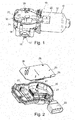
- a wiper motor 10 for at least indirectly driving or moving at least one wiper blade not shown in the figures shown.
- the wiper motor 10 has an electric motor designed as a drive motor 11, the substantially cup-shaped housing 12 is connected at one end face with a three-part gear housing 15 here, in particular screwed.
- a transmission, not shown, such as reduction gear for reducing the rotational speed of the drive motor 11 while increasing its torque is arranged, which is coupled to the drive motor 11 or coupled.
- From the gear housing 15 occurs in the Fig. 1 recognizable drive shaft 16 with a toothed portion 17 out, wherein the toothing portion 17th is connectable, for example, with a wiper linkage, which in turn is connected to, for example, two wiper blades.
- the gear housing 15 has in the illustrated embodiment, at least one gear housing base 18, which is closable with a housing element in the form of a housing cover 20, in particular by means of several, in the Fig. 1 recognizable fastening screws 21.
- the housing cover 20 is preferably made of plastic and formed as an injection molded part. However, it is also possible that the housing cover 20 is made of metal. In this case, the housing cover 20 is preferably formed as an aluminum die-cast part.
- a plug connection 22 which can be contacted with a corresponding mating connector of a cable harness of the motor vehicle (not shown), is integrally formed on the housing cover 20 in one piece.
- the connector terminal 22 is the electrical contact, that is, the control and the power supply of the wiper motor 10, instead.
- the outer plug connection 22 could also be formed separately from the housing.
- a circuit carrier in the form of a printed circuit board 25 can be seen, are arranged on the electrical or electronic components for the wiper motor 10, so that the circuit board can serve as a controller with at least one processor and a memory to its control.
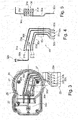
- the circuit board 25 has in the illustrated embodiment, three through holes 26, via which the circuit board 25 is connected to the housing cover 20 in alignment with the through holes 26 arranged locking domes 27 by means of a latching connection.
- the electrical contacting of the printed circuit board 25 or arranged on the printed circuit board 25 Components take place via a plurality of current-carrying elements 30 arranged in the housing cover 20.
- the housing cover 20 associated with the current-carrying elements 30 are arranged as separately formed current-carrying elements 30 in the housing cover 20.
- the current-carrying elements 30 could also be arranged in the other parts of the gear housing 15, such as the gear housing base 18, and in particular so that they are made in one piece.
- four current-carrying elements 30a to 30d which connect the printed circuit board 25, which in the present case is surrounded by the gear housing base part 18 and the Geotrosuedeckel 20, with the plug connection 22.
- the current-carrying elements 30 are led out of the housing to the outside through the outer plug connection 22.
- a current-carrying element 30e can be seen, which serves as ground contact and connects the printed circuit board 25 to the (electrical) ground of the wiper motor 10 in an electrically conductive manner.
- the current-carrying elements 30a to 30e are each formed, at least in regions, from a bending-resistant wire section of the correspondingly required length.
- a wire section is understood to mean that a wire section of the required length is separated from an endless wire, in particular in coil form, from which the current guiding element 30, 30a to 30e is formed, in particular by cutting to the desired length and corresponding, in particular repeated, permanent forming such as bending becomes.
- the current-carrying elements 30, 30a to 30e have in the illustrated embodiment at their respective end regions in each case a contact portion 31 a to 31 e and 32a to 32e, wherein in the present case the contact portions 31 a to 31 e respectively serve the electrical contacting of the circuit board 25 and in an inner Plug terminal 23 may be received, while in the present case, the contact portions 32a to 32d are disposed within the outer plug terminal 22 and the contact portion 32e forms the ground contact. It is essential that the contact portions 31 a to 31 e and 32 a to 32 e can each have a different from the otherwise particular round cross-section of the starting material cross-section.
- the contact portions 31 a to 31 e and 32 a to 32 e may have a rectangular or nearly rectangular cross-section, which can be achieved in particular by flattening the circular starting material on at least one side.
- the arranged within the outer connector terminal 22 contact portions 32a to 32d, which are contacted with the vehicle-side mating connector, adapted to the respective mating connector.
- the contact portions 32a to 32d beveled or at least on one, preferably two sides flattened ends 35, in particular in the Fig. 7 are recognizable.
- this means that the contact portions 32a to 32d, as shown in FIG FIG. 3 is shown can be designed so that they at the same time the contacts or pins of the connector terminal 22, in which engages the mating connector form.
- these contact portions 32a to 32d may be designed such that they are designed to be complementary to the mating connector and establish an electrically conductive connection with the corresponding contact portions of the mating connector in the mated condition.
- the current-carrying elements 30, 30a to 30e and the contact portions 32a to 32d be integral with each other.
- the contacts or contact pins of the outer plug terminal 22, which engage in the correspondingly designed contacts or contact pins of the mating connector, be designed separately, as described below in particular for the drive motor 11 or the circuit board 25 facing the end of the current-carrying element 30, 30a to 30e becomes.
- the separately provided for the current-carrying elements 37 contacts or pins of the connector terminal 22 are then connected to the contact portions 32a to 32d cohesively, for example by welding. The same applies to the contact portions 31a to 31e, which can form the contacts of the inner connector terminal 23.
- the here electrically connected to the circuit board 25, in particular welded or soldered contact portions 31 a to 31 e have, according to the illustration of Fig. 5 . 6 and 8 separate pin-shaped extensions 36, 38 which serve as contacts or contact pins, which are insertable into the corresponding passage openings 26 of the printed circuit board 25 and electrically conductive with this.
- the current-carrying element 30e consists of two parts 37, 38 which each have a rectangular cross-section in an interconnected, in particular welded connection region 39 and overlap each other.
- the part 38 of the current-carrying element 30e which forms the contact portion 32e, formed together with the part 37 as a whole from a flat material.
- the contact sections 31a to 31e and 32a to 32e preferably have a cross-sectional area which at least substantially corresponds to the cross-sectional area of the current-carrying elements 30a to 30e in the areas in which no contact sections 31a to 31e and 32a to 32e are present. In particular, the ends 35 of the contact portions 32a to 32d and the region of the extensions 36 are excluded.
- the production of the contact portions 31a to 31e or 32a to 32e takes place after the current-conducting elements 30a to 30e have been cut to length and a bending usually taking place to the current-carrying elements 30a to adapt 30e of the contour of the housing cover 20 and the connector terminal 22, by a forming or embossing process.
- the housing cover 20 is at least partially made of plastic and is preferably designed as an injection molded part, it may optionally be provided that, as shown Fig. 4
- the current-carrying elements 30a to 30d are encapsulated in regions by the material of a carrier element 40 made at least partially of plastic.
- the support member 40 with the Strom enclosuresettin 30a to 30d to connect in any other way with the housing cover 20.
- the current-carrying element 30e consisting of its two parts 37 and 38, in the connecting region 39, in which the two parts 37, 38 are welded together, each having a rectangular (preferably equal) cross-section. Furthermore, it can be seen that the current-carrying element 30e has, on the side facing the printed circuit board 25, a round cross-section which merges with the connecting region 39 into the rectangular cross-section.
- FIG. 7 the different cross-sections in the current-carrying elements 30a to 30d in the contact portions 32a to 32d can be seen.
- the essentially rectangular cross-section in the contact section 32a to 32d whose cross-sectional area at least substantially corresponds to the cross-sectional area of an intermediate section 43 between the contact sections 31a to 31d and 32a to 32d.
- the reduced cross-section of the contact portions 31a to 31d in the region of the projections 36 can be seen.
- This is there, for example fork-like executed with two prongs.
- other forms, with several or only one prong, as in FIG. 5 would also be conceivable.
- the material of the housing cover 20, the current-carrying elements 30a to 30e on the inside of the housing cover 20 side facing not (completely) encapsulated, or that the housing cover 20 is not made of (non-electrically conductive) plastic, but of metal it can be provided that the exposed portions of the current-carrying elements 30a to 30e, inside the housing cover 20 arranged and in particular the circuit board 25 (see Fig.
- FIGS. 9 and 10 show the inside of a housing element according to the invention, whereas Fig. 10 a partially sectioned view of the FIG. 9 shows. From the latter it can be seen that the current-carrying elements 30a to 30d - in this section of circular cross-section and are spaced apart separately. They are arranged between the protective element 45 and the housing element, in the present case the housing cover 20.
- the protective element 45 is at least partially connected to the housing element - for example by encapsulation, so that it faces the printed circuit board 25.
- the protective element 45 may be at least partially made of a material that serves as an electrical insulator. This avoids short circuits on the otherwise exposed areas of the current-carrying elements 30a to 30e.
- the protective element 45 can be designed separately and connected to the housing cover 20, for example via a rivet connection, a screw connection or the like. But it can also be integral with the housing element.
- the wiper motor 10 described so far, or the housing element designed as a housing cover 20, can be modified or modified in a variety of ways without deviating from the idea of the invention.
- This consists in forming the electrically contacting current-carrying elements 30a to 30e of a particular circular cross-section having rigid wire as the starting material, in the region of the contact portions 31 a to 31 e and 32a to 32e by an embossing step deviating from the circular cross-section shape or may have a different cross-section.
Landscapes
- Engineering & Computer Science (AREA)
- Power Engineering (AREA)
- Motor Or Generator Frames (AREA)
Abstract
Die Erfindung betrifft ein Gehäuseelement (20) für einen Wischermotor (10), wobei das Gehäuseelement (20) mit wenigstens einem Stromführungselement (30; 30a bis 30e) verbunden ist, das an vorzugsweise gegenüberliegenden Endbereichen jeweils einen Kontaktabschnitt (31 a bis 31 e, 32a bis 32e) aufweist, wobei das wenigstens eine Stromführungselement (30; 30a bis 30e) aus einem starren, metallischen Element besteht, dessen Querschnitt an den beiden Kontaktabschnitten (31 a bis 31e, 32a bis 32e) einem mit dem jeweiligen Kontaktabschnitt (31 a bis 31e, 32a bis 32e) verbindbaren Gegenelement angepasst ist. Erfindungsgemäß ist es vorgesehen, dass das Stromführungselement (31 a bis 31 e, 32a bis 32e) aus einem biegesteifen Drahtabschnitt ausgebildet ist.The invention relates to a housing element (20) for a wiper motor (10), wherein the housing element (20) is connected to at least one current-carrying element (30; 30a to 30e) which in each case has a contact section (31a to 31e) at preferably opposite end regions. 32a to 32e), wherein the at least one current-carrying element (30; 30a to 30e) consists of a rigid, metallic element whose cross-section at the two contact portions (31 a to 31 e, 32 a to 32 e) with the respective contact portion (31 a to 31e, 32a to 32e) is adapted counterpart element. According to the invention, it is provided that the current-carrying element (31 a to 31 e, 32a to 32e) is formed from a rigid wire section.
Description
Die Erfindung betrifft ein Gehäuseelement für einen Wischermotor nach dem Oberbegriff des Anspruchs 1. Ferner betrifft die Erfindung ein Verfahren zum Herstellen eines erfindungsgemäßen Gehäuseelements sowie einen Wischermotor unter Verwendung eines erfindungsgemäßen Gehäuseelements.The invention relates to a housing element for a wiper motor according to the preamble of claim 1. Furthermore, the invention relates to a method for producing a housing element according to the invention and a wiper motor using a housing element according to the invention.
Ein Gehäuseelement nach dem Oberbegriff des Anspruchs 1 ist aus dem Stand der Technik bereits bekannt. Es dient als Bestandteil eines Getriebegehäuses bei einem Wischermotor und ist in Form eines Gehäusedeckels ausgebildet. Der bekannte Gehäusedeckel weist einen Steckeranschluss zur elektrischen Kontaktierung des Wischermotors auf, wobei der Steckeranschluss innerhalb des Getriebegehäuses mit einem Schaltungsträger in Form einer Leiterplatte für den Wischermotor elektrisch kontaktiert ist. Die Leiterplatte ist wiederum elektrisch mit dem eigentlichen Wischermotor beziehungsweise Elektromotor verbunden. Die Verbindung zwischen dem Steckeranschluss, der mit einem kundenseitigen Fahrzeuggegenstecker kontaktierbar ist, und der Leiterplatte und/oder zwischen der Leiterplatte und dem Elektromotor erfolgt mittels starrer Stromführungselemente, die als Stanz-/Prägeteile aus einem zunächst flachen Blech ausgebildet sind. Hierzu werden die der elektrischen Kontaktierung dienenden Stromführungselemente üblicherweise gleichzeitig (mit den entsprechenden Abständen zwischen den Stromführungselementen) aus einer größeren Blechplatte als Stanzgitter ausgestanzt, wobei die Stromführungselemente zur Anpassung an die Geometrie des Gehäuseelements und der Anordnung der zu kontaktierenden Teile oftmals in einem Winkel zueinander angeordnete Teilabschnitte aufweisen. Nach dem Stanzen werden die Stromführungselemente in einem Prägewerkzeug weiterbearbeitet, um die Stromführungselemente der Kontur des Gehäuseelements anzupassen. Die so ausgebildeten Stromführungselemente werden dann (bei einer Ausbildung des Gehäuseelements aus Kunststoff) in ein entsprechendes Spritzgusswerkzeug für das Gehäuseelement eingelegt und von dem Kunststoff des Gehäuseelements, Kontaktabschnitte freilassend, umspritzt. Dadurch, dass die Stromführungselemente aus einem plattenförmigen Blech ausgestanzt werden, weisen diese üblicherweise einen rechteckförmigen Querschnitt auf, wobei der Querschnitt, beispielsweise in dem Bereich des Steckeranschlusses, durch einen Stanz-/Prägeschritt gegebenenfalls einem Gegenstecker angepasst wird. Nachteilig dabei ist, dass bei der Fertigung derartiger Stromführungselemente, beispielsweise für einen Wischermotor, ein relativ großer Stanzabfall anfällt und dass zum Formen beziehungsweise zum Biegen der Stromführungselemente relativ aufwändig ausgebildete Prägewerkzeuge erforderlich sind.A housing element according to the preamble of claim 1 is already known from the prior art. It serves as part of a transmission housing in a wiper motor and is designed in the form of a housing cover. The known housing cover has a plug connection for electrically contacting the wiper motor, wherein the plug connection is electrically contacted within the transmission housing with a circuit carrier in the form of a printed circuit board for the wiper motor. The circuit board is in turn electrically connected to the actual wiper motor or electric motor. The connection between the connector terminal, which is contactable with a customer-side vehicle mating connector, and the circuit board and / or between the circuit board and the electric motor by means of rigid current-carrying elements, which are formed as stamping / embossing parts of a first flat sheet metal. For this purpose, the electric contacting serving current guide elements are usually at the same time (with the appropriate distances between the current-carrying elements) from a larger sheet metal plate than Stamped punched grid, wherein the current-carrying elements often have to be adapted to the geometry of the housing member and the arrangement of the parts to be contacted at an angle to each other arranged subsections. After punching, the current-carrying elements are further processed in an embossing tool in order to adapt the current-carrying elements to the contour of the housing element. The current-carrying elements thus formed are then inserted (in the case of a design of the housing element made of plastic) into a corresponding injection-molding tool for the housing element and encapsulated by the plastic of the housing element, leaving exposed contact sections. Characterized in that the current-carrying elements are punched out of a plate-shaped plate, they usually have a rectangular cross-section, wherein the cross section, for example in the region of the connector terminal, is adapted by a punching / embossing step optionally a mating connector. The disadvantage here is that in the production of such current-carrying elements, for example for a wiper motor, a relatively large punch waste is obtained and that relatively expensive trained for forming or bending of the current-carrying elements embossing tools are required.
Aus der
Ausgehend von dem dargestellten Stand der Technik liegt der Erfindung die Aufgabe zugrunde, ein Gehäuseelement für einen Wischermotor nach dem Oberbegriff des Anspruchs 1 derart weiterzubilden, dass eine herstellungstechnisch besonders einfache und kostengünstig ausgebildete Konstruktion des Gehäuseelements mit wenigstens einem Stromführungselement ermöglicht wird. Insbesondere sollen die beim Stand der Technik üblicherweise anfallenden Stanzgitterabfälle vermieden werden und möglichst einfache sowie kostengünstig herstellbare Werkzeuge zum Formen beziehungsweise Biegen der Stromführungselemente ermöglicht werden.Based on the illustrated prior art, the invention has the object, a housing element for a wiper motor according to the preamble of claim 1 such that a manufacturing technology particularly simple and inexpensive designed construction of the housing element is made possible with at least one current-carrying element. In particular, the customary in the prior art punched grid waste should be avoided and possible simple and inexpensive to produce tools for forming or bending the current-carrying elements are made possible.
Diese Aufgabe wird erfindungsgemäß bei einem Gehäuseelement für einen Wischermotor mit den Merkmalen des Anspruchs 1 dadurch gelöst, dass das Stromführungselement aus einem biegesteifen Drahtabschnitt ausgebildet ist.This object is achieved in a housing element for a wiper motor with the features of claim 1, characterized in that the current-carrying element is formed of a rigid wire section.
Unter Gegenelement im Sinne der vorliegenden Erfindung wird ein elektrischer Leiter verstanden, der über entsprechende Kontakte mit dem wenigstens einen Stromführungselement elektrisch verbindbar ist.Under counter element in the context of the present invention, an electrical conductor is understood, which is electrically connectable via corresponding contacts with the at least one current-carrying element.
Ein solches Gegenelement kann damit selbst ein erfindungsgemäßes Stromführungselement, also ein Drahtabschnitt sein, der beispielsweise eine Masseleitung, einen Abzweig aus dem Stromführungselement oder die Kontaktstifte eines inneren oder äußeren Steckeranschlusses darstellt. Auch kann das Gegenelement ein Kontakt sein, der Kontaktabschnitte aufweist, die elektrisch lösbar mit den Kontaktabschnitten des wenigstens einen Stromführungselements verbindbar sind. In anderen Worten bedeutet dies, dass das Gegenelement wenigstens als ein Kontaktabschnitt eines Gegensteckers, der separat und lösbar mit dem inneren oder äußeren Steckeranschluss elektrisch verbindbar sein kann, ausgebildet ist. Beispielsweise können dann die Kontaktabschnitte des inneren oder äußeren Steckeranschlusses entsprechend der Geometrie der Kontaktabschnitte des Gegensteckers ausgeführt sein. Bei verbundenem Steckeranschluss und Gegenstecker ergibt sich somit ein Stromfluss zwischen den beiden Kontaktabschnitten des jeweiligen Steckeranschluss und seines entsprechenden Gegensteckers. Bei getrenntem Steckeranschluss und Gegenstecker wird der Stromfluss entsprechend unterbrochen.Such a counter element can thus itself be a current-carrying element according to the invention, ie a wire section which, for example, represents a ground line, a branch from the current-carrying element or the contact pins of an inner or outer plug connection. Also, the counter-element may be a contact having contact portions which are electrically releasably connectable to the contact portions of the at least one current-carrying member. In other words, this means that the counter element is designed at least as a contact portion of a mating connector, which can be separately and detachably connected to the inner or outer connector terminal, electrically connected. For example, then the contact portions of the inner or outer plug connector can be designed according to the geometry of the contact portions of the mating connector. When connected connector and mating connector thus results in a current flow between the two contact portions of the respective connector and its corresponding mating connector. With separate plug connection and mating plug, the current flow is interrupted accordingly.
Das Gehäuseelement kann einen Teil oder das vollständige Gehäuse bilden, welches bei der Anwendung als Wischermotor den als Elektromotor ausgebildeten Antriebsmotor, das dem Antriebsmotor zugehörige Getriebe und/oder die zur Ansteuerung des Antriebsmotors benötigte Leiterplatte wenigstens teilweise umgibt. So kann das vollständige Gehäuse von mehreren Gehäuselementen gebildet werden. Das wenigstens eine Stromführungselement kann insbesondere einteilig (z.B. eingegossen) mit derjenigen Wandung des Gehäuseelements ausgeführt sein, die im zusammengebauten Zustand dem Antriebsmotor, dem zugehörigen Getriebe und/oder der Leiterplatte zugewandt ist.The housing element may form a part or the complete housing which, when used as a wiper motor, at least partially surrounds the drive motor designed as an electric motor, the transmission associated with the drive motor and / or the circuit board required for driving the drive motor. Thus, the complete housing can be formed by a plurality of housing elements. The at least one current-carrying element can in particular be made in one piece (eg cast-in) with that wall of the housing element which in the assembled state faces the drive motor, the associated gear and / or the printed circuit board.
Auf der Leiterplatte sind dabei elektrische beziehungsweise elektronische Bauteile für den Wischermotor angeordnet, sodass die Leiterplatte als Steuerung mit insbesondere wenigstens einem Prozessor und einem Speicher zu dessen Ansteuerung, insbesondere unabhängig von einer vorhandenen Fahrzeugsteuerung, dienen kann.On the circuit board while electrical or electronic components for the wiper motor are arranged, so that the circuit board as a controller with in particular at least one processor and a memory for its control, in particular independently of an existing vehicle control, can serve.
Das Stromführungselement gemäß der vorliegenden Erfindung ist ein elektrischer Leiter. Unter einem Drahtabschnitt wird dabei im Rahmen der Erfindung ein üblicherweise beispielsweise auf einer Drahtspule bevorrateter Abschnitt eines (endlosen) biegesteifen Drahtes verstanden, der als Ausgangsmaterial von der Drahtrolle in der entsprechenden Länge abgetrennt wird. Mit anderen Worten gesagt bedeutet dies, dass für jedes Stromführungselement ein entsprechender, separater Drahtabschnitt verwendet wird, so dass sich derartige Stromführungselemente unter Verzicht eines Stanzverfahrens besonders einfach herstellen lassen. So kann jeder Drahtabschnitt einzeln durch Umformen und Ablängen des Drahtabschnitts von der Drahtrolle entstehen.The current-carrying element according to the present invention is an electrical conductor. In the context of the invention, a section of wire is understood to mean, for example, a section of an (endless) rigid wire which is usually stored, for example, on a wire coil and which is separated from the wire roll in the corresponding length as the starting material. In other words, this means that a corresponding, separate wire section is used for each current-carrying element, so that such current-carrying elements can be produced in a particularly simple way without the use of a punching method. Thus, each wire section may be formed individually by reshaping and cutting the wire section from the wire roll.
Wesentlich ist, dass der Drahtabschnitt biegesteif ist, das bedeutet aus einem Material hergestellt ist, welches nach dessen Umformung - ohne eine verhältnismäßig große äußere Krafteinwirkung hierauf - die ihm durch die Umformung verliehene Ausgangsform beibehält. In anderen Worten ist das Material des Drahtabschnitts so gewählt, dass es seine ihm nach der Umformung verliehene Gestalt infolge äußerer Krafteinwirkung nur unter Überwindung eines mechanischen Widerstands ändert. Der mechanische Widerstand kann dabei derart gewählt sein, dass es im bei der Herstellung des Gehäuseelements oder beim Betrieb des Wischermotors, insbesondere unter den hierfür vorgesehenen Einsatzfällen, nicht zu einer Änderung der dem Drahtabschnitt nach der Umformung verliehenen Gestalt kommt.It is essential that the wire section is rigid, that is made of a material which, after its transformation - without a relatively large external force acting on it - retains the initial shape imparted by the deformation. In other words, the material of the wire section is chosen so that it changes its shape given to it after the deformation due to external force only by overcoming a mechanical resistance. The mechanical resistance can be chosen such that in the case of the production of the housing element or during operation of the wiper motor, in particular under the intended use cases, there is no change in the shape given to the wire section after the deformation.
Das Ausgangsmaterial für das Stromführungselement beziehungsweise für den Drahtabschnitt kann als ein Einzeldraht oder Einzelader ausgebildet sein.The starting material for the current-carrying element or for the wire section may be formed as a single wire or single core.
Insbesondere ist es gemäß der breitesten Ausführungsform der Erfindung unwesentlich, welchen Querschnitt (beispielsweise rund, mehreckig oder quadratisch) der Drahtabschnitt aufweist. Wesentlich ist lediglich, dass der Querschnitt derart bemessen ist, dass beispielsweise ein bestimmter elektrischer Widerstand nicht überschritten wird.In particular, according to the broadest embodiment of the invention, it is immaterial which cross-section (for example round, polygonal or square) the wire section has. It is only essential that the cross section is dimensioned such that, for example, a certain electrical resistance is not exceeded.
Vorteilhafte Weiterbildungen des erfindungsgemäßen Gehäuseelements für einen Wischermotor sind in den Unteransprüchen aufgeführt.Advantageous developments of the housing element according to the invention for a wiper motor are listed in the subclaims.
In besonders bevorzugter Ausgestaltung der Stromführungselemente ist es vorgesehen, dass der Drahtabschnitt, insbesondere dessen Ausgangsmaterial zumindest gegebenenfalls mit Ausnahme in den Kontaktabschnitten, einen runden Querschnitt aufweist. Eine derartige Ausbildung hat den Vorteil, dass ein besonders einfaches Umformen wie z.B. Biegen beziehungsweise Prägen der Stromführungselemente ermöglicht wird, da unabhängig von der Lage des Stromführungselements in alle Richtungen ein Biegen, auch in Form einer Krümmung bzw. eines Radius, ermöglicht wird.In a particularly preferred embodiment of the current-carrying elements, it is provided that the wire section, in particular its starting material, at least optionally with the exception in the contact sections, has a round cross-section. Such a design has the advantage that a particularly simple forming such. Bending or embossing of the current-carrying elements is made possible, since regardless of the position of the current-carrying element in all directions bending, even in the form of a curvature or a radius, is made possible.
Um eine kundenspezifische Kontaktierungsmöglichkeit mit einem fahrzeugseitigen Gegenstecker zu ermöglichen, die herstellungstechnisch besonders einfach realisierbar ist, wird vorgeschlagen, dass die Kontaktabschnitte einen im Wesentlichen rechteckigen Querschnitt aufweisen, der vorzugsweise durch einen Umform- beziehungsweise Prägeschritt erzeugt ist, und dass die Querschnittsfläche des Drahtes an den Kontaktabschnitten und in dem Bereich zwischen den Kontaktabschnitten zumindest im Wesentlichen gleich groß ist.In order to enable a customer-specific contacting possibility with a vehicle-side mating connector, which is particularly easy to manufacture, it is proposed that the contact portions have a substantially rectangular cross-section, which is preferably produced by a forming or embossing step, and that the cross-sectional area of the wire to the Contact portions and in the area between the contact portions is at least substantially equal.
Das Ausgangsmaterial für das Stromführungselement beziehungsweise für den Drahtabschnitt kann frei von einer Ummantelung sein, die beispielsweise als elektrische Isolation dient.The starting material for the current-carrying element or for the wire section may be free of a sheath which serves, for example, as electrical insulation.
Um eine definierte Lage des Stromführungselements in beziehungsweise am Gehäuseelement zu ermöglichen, und um darüber hinaus die Gefahr von elektrischen Kurzschlüssen insbesondere in den Bereichen, in denen keine elektrische Kontaktierung mit Gegenelementen vorgesehen ist, zu vermeiden, wird vorgeschlagen, dass das Stromführungselement zumindest bereichsweise von dem Material des Gehäuseelements, bevorzugt Kunststoff und insbesondere elektrisch nicht leitender Kunststoff umspritzt ist. Damit wird erreicht, dass das wenigstens eine Stromführungselement einteilig mit dem Gehäuseelement ist und als elektrischer Isolator dient.In order to enable a defined position of the current-carrying element in or on the housing element, and moreover to avoid the risk of electrical short circuits, especially in the areas in which no electrical contact with counter elements is provided, it is proposed that the current-carrying element be at least partially of the Material of the housing element, preferably plastic and in particular electrically non-conductive plastic is encapsulated. This ensures that the at least one current-carrying element is integral with the housing element and serves as an electrical insulator.
Um mehrere Stromführungselemente gleichzeitig in ihrer Lage zum Gehäuseelement zu positionieren, sowie um eine besonders einfache Herstellbarkeit beziehungsweise Verbindung der Stromführungselemente mit dem Gehäuseelement zu erzielen, wird vorgeschlagen, dass mehrere Stromführungselemente kraft-, form- und/oder stoffschlüssig mittels eines Trägerelements zu einem einzigen als Montageeinheit wirkenden Teil zusammengefasst werden. Zur Erzielung eines Stoffschlusses zwischen Stromführungselementen und Trägerelement können die Stromführungselemente mit dem Kunststoffs des Trägerelements umspritzt werden. Die mehreren Stromführungselemente, die zu dem Trägerelement zusammengefasst sind, stellen somit eine relativ starre, vorgefertigte Baueinheit dar, die anschließend entweder mit dem Gehäuseelement zum Beispiel kraft- und/oder formschlüssig verbunden werden kann. Alternativ dazu (bevorzugt) kann diese Baueinheit dann von demselben Kunststoff woraus auch das Gehäuseelements wenigstens teilweise hergestellt wurde, umspritzt werden.In order to position several current-carrying elements simultaneously in their position to the housing element, and to achieve a particularly simple manufacturability or connection of the current-carrying elements to the housing element, it is proposed that a plurality of current-carrying elements non-positively, positively and / or cohesively by means of a carrier element to a single Assembly unit acting part can be summarized. In order to achieve a material bond between the current-carrying elements and the carrier element, the current-carrying elements can be encapsulated with the plastic of the carrier element. The multiple current-carrying elements, which are combined to form the carrier element, thus constitute a relatively rigid, prefabricated structural unit, which can then be connected to the housing element, for example, in a non-positive and / or positive-locking manner. Alternatively (preferred), this unit can then from the same plastic from which the housing member has been at least partially made, to be encapsulated.
Um auch bei derartigen Ausführungsformen, bei denen die Stromführungselemente relativ ungeschützt im beziehungsweise am Gehäuseelement angeordnet sind, einen hinreichend guten Schutz vor elektrischen Kurzschlüssen zu ermöglichen, wird vorgeschlagen, dass das wenigstens eine Stromführungselement von einem separaten Schutzelement, das als elektrischer Isolator wirkt, zumindest bereichsweise überdeckt ist.In order to allow a sufficiently good protection against electrical short circuits even in such embodiments in which the current-carrying elements are arranged relatively unprotected in or on the housing element, it is proposed that the at least one current-carrying element of a separate protective element, which acts as an electrical insulator, at least partially is covered.
Nach einer weiteren Ausführungsform kann ein äußerer Steckeranschluss auf der Außenseite des Gehäuseelements angeordnet und bevorzugt einteilig mit diesem ausgeführt sein, wobei das dem äußeren Steckeranschluss zugewandte Ende des Stromführungselements in dem äußeren Steckeranschluss aufgenommen ist, sodass die Kontaktabschnitte gleichzeitig die Kontakte des äußeren Steckeranschlusses ausbilden, die mit Kontakten eines als Gegenelement fungierenden äußeren Gegensteckers elektrisch verbindbar sind.According to a further embodiment, an outer plug connection can be arranged on the outer side of the housing element and preferably configured integrally therewith, wherein the end of the current-carrying element facing the outer plug connection is received in the outer plug connection, so that the contact sections simultaneously form the contacts of the outer plug connection can be electrically connected to contacts of acting as a counter element outer mating connector.
Gemäß einer weiteren Ausführungsform kann ein innerer Steckeranschluss auf der Innenseite des Gehäuseelements angeordnet und bevorzugt einteilig mit diesem ausgeführt sein, wobei das dem inneren Steckeranschluss zugewandte Ende des Stromführungselements in dem inneren Steckeranschluss aufgenommen ist, sodass die Kontaktabschnitte gleichzeitig die Kontakte des inneren Steckeranschlusses ausbilden, die mit Kontakten eines als Gegenelement fungierenden inneren Gegensteckers kontaktierbar sind.According to a further embodiment, an inner plug connection may be arranged on the inner side of the housing element and preferably be integral therewith, wherein the end of the current-carrying element facing the inner plug connection is received in the inner plug connection, so that the contact sections simultaneously form the contacts of the inner plug connection can be contacted with contacts of acting as a counter element inner mating connector.
Insbesondere bei den letzten beiden Ausführungsformen, aber auch generell, kann das wenigstens eine Stromführungselement im Bereich des inneren und äußeren Steckeranschlusses von dem Kunststoff des Gehäuseelements, insbesondere die Kontaktabschnitte freilassend, umspritzt sein.In particular, in the last two embodiments, but also in general, the at least one current-carrying element in the region of inner and outer connector terminal of the plastic of the housing member, in particular the contact portions releasing, be encapsulated.
Die Erfindung umfasst auch ein Verfahren zum Herstellen eines erfindungsgemäßen Gehäuseelements, bei dem wenigstens ein Stromführungselement mit einem Gehäuseelement verbunden wird, wobei das Verfahren durch folgende Herstellungsschritte gekennzeichnet ist:
- Ablängen wenigstens eines Drahtabschnitts von einem einen konstanten, insbesondere runden Querschnitt aufweisenden, endlosen biegesteifen Draht
- Gegebenenfalls Biegen des Drahtabschnitts
- Ändern des Querschnitts des Drahts an wenigstens einem Kontaktabschnitt
- Zumindest mittelbares Befestigen des Drahtabschnitts an einem Gehäuseelement.
- Cutting at least one wire section from a continuous, in particular round cross-section having endless rigid wire
- Optionally, bending the wire section
- Changing the cross section of the wire on at least one contact section
- At least indirectly attaching the wire portion to a housing element.
Beim Ablängen wird der Drahtabschnitt auf die gewünschte Länge gebracht, die im Wesentlichen der nach der Herstellung des Gehäuseelements erzielten Länge des Drahtabschnitts entspricht, d.h. von seinem einen Endbereich zu seinem anderen gegenüberliegenden Endbereich. Dadurch lassen sich beispielsweise Stromführungselemente herstellen, die vollständig über die gesamte Länge aus einem einzigen Drahtabschnitt hergestellt sind. Natürlich können die Stromführungselement auch aus mehreren zusammengefügten Drahtabschnitten bestehen.When cutting to length, the wire section is brought to the desired length, which corresponds essentially to the length of the wire section obtained after the manufacture of the housing element, ie from its one end area to its other opposite end area. As a result, it is possible, for example, to produce current-conducting elements which are produced completely over the entire length from a single wire section. Of course, the current-carrying element can also consist of several joined wire sections.
Biegen bedeutet hier ein entsprechendes insbesondere mehrmaliges, bleibendes Umformen des Drahtabschnitts.Bending here means a corresponding in particular repeated, permanent forming of the wire section.
Insbesondere die erfindungsgemäßen Verfahrensschritte des Biegens und Ändern des Querschnitts können grundsätzlich in beliebiger Reihenfolge erfolgen.In particular, the method steps according to the invention of bending and changing the cross section can in principle be carried out in any order.
Auch können alle erfindungsgemäßen Verfahrensschritte zu einzigen Fertigungsprozess zusammengefasst sein und in einem einzigen Werkzeug herstellbar sein.All the method steps according to the invention can also be combined to form a single production process and can be produced in a single tool.
In einer bevorzugten Ausgestaltung des erfindungsgemäßen Verfahrens ist es vorgesehen, dass mehrere Stromführungselemente von dem Kunststoff des Trägerelements zumindest bereichsweise umspritzt werden, und dass der Verbund aus den mehreren Stromführungselementen und dem Trägerelement anschließend von dem Kunststoff des Gehäuseelements zumindest bereichsweise umspritzt wird, oder dass der Verbund aus den mehreren Stromführungselementen und dem Trägerelement anschließend mit dem aus Metall bestehenden Gehäuseelement verbunden wird. Dabei kann es sich bei dem Kunststoff des Gehäuseelements und dem Kunststoff des Trägerelements um denselben oder unterschiedlichen Kunststoff handeln. Auch hier gilt das zu dem Kunststoff des Gehäuseelements Gesagte.In a preferred embodiment of the inventive method, it is provided that a plurality of current-carrying elements are encapsulated at least partially by the plastic of the carrier element, and that the composite of the plurality of current-carrying elements and the carrier element is then encapsulated at least partially by the plastic of the housing element, or that the composite is then connected from the plurality of current-carrying elements and the carrier element with the housing element consisting of metal. In this case, the plastic of the housing element and the plastic of the carrier element may be the same or different plastic. Again, this is true for the plastic of the housing element.
Weiterhin umfasst die Erfindung einen Wischermotor mit einem erfindungsgemäßen Gehäuseelement. Der Wischermotor kann dann einen als Elektromotor ausgebildeten Antriebsmotor, ein zur Drehzahl-/Drehmomentwandlung mit dem Antriebsmotor gekoppeltes oder koppelbares Getriebe und/oder eine zur Ansteuerung des Antriebsmotors benötigte Leiterplatte aufweisen. Das Gehäuseelement kann dann wenigstens eines dieser Teile wenigstens teilweise umgeben.Furthermore, the invention comprises a wiper motor with a housing element according to the invention. The wiper motor can then have a drive motor embodied as an electric motor, a transmission coupled or coupleable to the drive motor for speed / torque conversion and / or a printed circuit board required for driving the drive motor. The housing element may then at least partially surround at least one of these parts.
Damit kann das wenigstens eine Stromführungselement mit seinem einen Endbereich elektrisch an den Wischermotor und/oder die Leiterplatte, bevorzugt unter Zwischenschaltung eines inneren Steckeranschlusses, und mit seinem anderen Endbereich elektrisch an einen äußeren Steckeranschluss elektrisch leitend anschließbar sein. Dabei ist es denkbar, dass das Stromführungselement zwischen diesen beiden Steckeranschlüssen einteilig oder mehrteilig, das bedeutet aus einem einzigen oder mehreren zusammengefügten Drahtabschnitten ausgeführt ist.Thus, the at least one current-carrying element with its one end region can be electrically connected electrically to the wiper motor and / or the printed circuit board, preferably with the interposition of an inner plug connection, and with its other end region to an outer plug connection. It is conceivable that the current-carrying element between these two plug connections in one piece or in several parts, that is executed from a single or more joined wire sections.
In bevorzugter Ausgestaltung des Gehäuseelements ist dieses als ein Getriebedeckel eines Getriebegehäuses ausgebildet.In a preferred embodiment of the housing element, this is designed as a transmission cover of a transmission housing.
Weitere Vorteile, Merkmale und Einzelheiten der Erfindung ergeben sich aus der nachfolgenden Beschreibung bevorzugter Ausführungsbeispiele sowie anhand der Zeichnung.Further advantages, features and details of the invention will become apparent from the following description of preferred embodiments and from the drawing.
Diese zeigt in:
-
Fig.1 einen Wischermotor unter Verwendung eines erfindungsgemäßen Gehäuseelements in einer perspektivischen Ansicht, -
Fig. 2 einen Getriebedeckel mit einer in dem Getriebedeckel angeordneten Leiterplatte in Explosionsdarstellung, -
Fig. 3 den Getriebedeckel gemäßFig. 2 in teilweise geschnittener Draufsicht, -
Fig.4 die bei dem Getriebedeckel gemäß derFig. 2 und3 verwendeten Stromführungselemente in Draufsicht, -
Fig.5 die Stromführungselemente gemäßFig. 4 in einer Seitenansicht, -
Fig. 6 bis 8 jeweils unterschiedlich gestaltete Kontaktabschnitte an Stromführungselementen in Seitenansicht mit einer Darstellung der jeweiligen Querschnitte, -
Fig. 9 einen modifizierten Gehäusedeckel unter Verwendung eines Schutzelements zur Abdeckung von Stromführungselementen in einem Gehäuseelement und -
Fig. 10 einen Schnitt in der Ebene A-A derFig. 9 .
-
Fig.1 a wiper motor using a housing element according to the invention in a perspective view, -
Fig. 2 a gear cover with an arranged in the gear cover PCB in exploded view, -
Fig. 3 the gear cover according toFig. 2 in a partially sectioned plan view, -
Figure 4 in the transmission cover according to theFig. 2 and3 used current guide elements in plan view, -
Figure 5 the current-carrying elements according toFig. 4 in a side view, -
Fig. 6 to 8 each differently shaped contact sections of current-carrying elements in side view with a representation of the respective cross-sections, -
Fig. 9 a modified housing cover using a protective element for covering current-carrying elements in a housing element and -
Fig. 10 a section in the plane AA theFig. 9 ,
Gleiche Elemente beziehungsweise Elemente mit gleicher Funktion sind in den Figuren mit den gleichen Bezugsziffern versehen.The same elements or elements with the same function are provided in the figures with the same reference numerals.
In der
Das Getriebegehäuse 15 weist im dargestellten Ausführungsbeispiel wenigstens ein Getriebegehäusegrundteil 18 auf, das mit einem Gehäuseelement in Form eines Gehäusedeckels 20 verschließbar ist, insbesondere mittels mehrerer, in der
An dem Gehäusedeckel 20 ist vorliegend einstückig ein Steckeranschluss 22 angeformt, der mit einem entsprechenden Gegenstecker eines Kabelbaums des Kraftfahrzeugs kontaktierbar ist (nicht dargestellt). Über den Steckeranschluss 22 findet die elektrische Kontaktierung, das heißt die Ansteuerung sowie die Spannungsversorgung des Wischermotors 10, statt. Alternativ könnte der äußere Steckeranschluss 22 auch separat zu dem Gehäuse ausgebildet sein.In the present case, a
In der
Erfindungsgemäß ist es vorgesehen, dass die Stromführungselemente 30a bis 30e jeweils zumindest bereichsweise aus einem biegesteifen Drahtabschnitt der entsprechend benötigten Länge ausgebildet werden. Unter einem Drahtabschnitt wird verstanden, dass von einen insbesondere in Spulenform bevorrateten, endlosen Draht ein Drahtabschnitt der benötigten Länge abtrennt wird, aus dem das Stromführungselement 30, 30a bis 30e insbesondere durch Ablängen auf die gewünschte Länge und entsprechendes insbesondere mehrmaliges, bleibendes Umformen wie Biegen gebildet wird. Diese Schritte können in einem einzigen Fertigungsprozess zusammengefasst sein. In besonders bevorzugter Ausgestaltung handelt es sich bei dem Draht um einen Draht mit rundem Querschnitt. Es ist jedoch auch denkbar, dass der Draht beispielsweise einen mehreckigen wie quadratischen Querschnitt aufweist.According to the invention, it is provided that the current-carrying
Die Stromführungselemente 30, 30a bis 30e weisen in dem dargestellten Ausführungsbeispiel an ihren jeweiligen Endbereichen jeweils einen Kontaktabschnitt 31 a bis 31 e sowie 32a bis 32e auf, wobei vorliegend die Kontaktabschnitte 31 a bis 31e jeweils der elektrischen Kontaktierung der Leiterplatte 25 dienen und in einem inneren Steckeranschluss 23 aufgenommen sein können, während vorliegend die Kontaktabschnitte 32a bis 32d innerhalb des äußeren Steckeranschlusses 22 angeordnet sind und der Kontaktabschnitt 32e den Massekontakt ausbildet. Wesentlich ist, dass die Kontaktabschnitte 31 a bis 31e sowie 32a bis 32e jeweils einen von dem ansonsten insbesondere runden Querschnitt des Ausgangsmaterials abweichenden Querschnitt aufweisen können. Insbesondere können die Kontaktabschnitte 31 a bis 31e sowie 32a bis 32e einen rechteckförmigen oder nahezu rechteckförmigen Querschnitt aufweisen, der insbesondere durch Abflachung des kreisrunden Ausgangsmaterials an wenigstens einer Seite erzielbar ist. Dabei sind die innerhalb des äußeren Steckeranschlusses 22 angeordneten Kontaktabschnitte 32a bis 32d, die mit dem fahrzeugseitigen Gegenstecker kontaktierbar sind, dem jeweiligen Gegenstecker angepasst. Hierzu weisen die Kontaktabschnitte 32a bis 32d abgeschrägte oder wenigstens an einer, bevorzugt auf zwei Seiten abgeflachte Enden 35 auf, die insbesondere in der
Alternativ können die Kontakte oder Kontaktstifte des äußeren Steckeranschlusses 22, die in die entsprechend ausgeführten Kontakte oder Kontaktstifte des Gegensteckers eingreifen, separat ausgeführt sein, wie dies nachfolgend insbesondere für das dem Antriebsmotor 11 oder der Leiterplatte 25 zugewandte Ende der Stromführungselement 30, 30a bis 30e beschrieben wird. Die separat zu den Stromführungselementen 37 vorgesehenen Kontakte oder Kontaktstifte des Steckeranschlusses 22 sind dann mit den Kontaktabschnitten 32a bis 32d stoffschlüssig beispielsweise durch Schweißen verbunden. Selbiges gilt auch für die Kontaktabschnitte 31a bis 31e, die die Kontakte des inneren Steckeranschlusses 23 ausbilden können.Alternatively, the contacts or contact pins of the
Die hier mit der Leiterplatte 25 elektrisch verbundenen, insbesondere verschweißten beziehungsweise verlöteten Kontaktabschnitte 31 a bis 31e weisen gemäß der Darstellung der
Bevorzugt weisen die Kontaktabschnitte 31 a bis 31e sowie 32a bis 32e eine Querschnittsfläche auf, die zumindest im Wesentlichen der Querschnittsfläche der Stromführungselemente 30a bis 30e in den Bereichen entspricht, in denen keine Kontaktabschnitte 31 a bis 31e sowie 32a bis 32e vorhanden sind. Ausgenommen davon sind insbesondere die Enden 35 der Kontaktabschnitte 32a bis 32d sowie der Bereich der Fortsätze 36. Die Fertigung der Kontaktabschnitte 31 a bis 31e beziehungsweise 32a bis 32e erfolgt nach dem Ablängen der Stromführungselemente 30a bis 30e und einem üblicherweise stattfindenden Biegen, um die Stromführungselemente 30a bis 30e der Kontur des Gehäusedeckels 20 beziehungsweise des Steckeranschlusses 22 anzupassen, durch einen Umform- oder Prägeprozess.The
Insbesondere für den Fall, dass unabhängig von den gezeigten Ausführungsformen der Gehäusedeckel 20 wenigstens teilweise aus Kunststoff hergestellt ist und bevorzugt als Spritzgussteil ausgebildet ist, kann es optional vorgesehen sein, dass entsprechend der Darstellung der
In der
In der
In der
Der soweit beschriebene Wischermotor 10 beziehungsweise das als Gehäusedeckel 20 ausgebildete Gehäuseelement können in vielfältiger Art und Weise abgewandelt beziehungsweise modifiziert werden, ohne vom Erfindungsgedanken abzuweichen. Dieser besteht darin, die der elektrischen Kontaktierung dienenden Stromführungselemente 30a bis 30e aus einem insbesondere einen runden Querschnitt aufweisenden biegesteifen Draht als Ausgangsmaterial auszubilden, der im Bereich der Kontaktabschnitte 31 a bis 31 e sowie 32a bis 32e durch einen Prägeschritt eine von dem runden Querschnitt abweichende Form beziehungsweise einen abweichenden Querschnitt aufweisen kann.The
- 1010
- Wischermotorwiper motor
- 1111
- Antriebsmotordrive motor
- 1212
- Gehäusecasing
- 1515
- Getriebegehäusegearbox
- 1616
- Antriebswelledrive shaft
- 1717
- Verzahnungsbereichtoothed area
- 1818
- GetriebegehäusegrundteilTransmission housing base
- 2020
- Gehäusedeckelhousing cover
- 2121
- Befestigungsschraubefixing screw
- 2222
- äußerer Steckeranschlussouter plug connection
- 2323
- innerer Steckeranschlussinner plug connection
- 2525
- Leiterplattecircuit board
- 2626
- DurchgangsöffnungThrough opening
- 2727
- RastdomRastdom
- 3030
- StromführungselementCurrent-carrying element
- 30a - 30e30a - 30e
- StromführungselementCurrent-carrying element
- 31a - 31e31a - 31e
- KontaktabschnittContact section
- 32a - 32e32a - 32e
- KontaktabschnittContact section
- 3535
- EndeThe End
- 3636
- Fortsatzextension
- 3737
- Teilpart
- 3838
- Teilpart
- 3939
- Verbindungsbereichconnecting area
- 4040
- Trägerelementsupport element
- 4141
- Montageeinheitassembly unit
- 4242
- Verbindungsbereichconnecting area
- 4343
- Zwischenbereichintermediate area
- 4545
- Schutzelementprotection element
Claims (14)
dadurch gekennzeichnet,
dass das Stromführungselement (31 a bis 31 e, 32a bis 32e) aus einem biegesteifen Drahtabschnitt ausgebildet ist.Housing element (20) for a wiper motor (10), wherein the housing element (20) with at least one current-carrying element (30; 30a to 30e) is connected, each having a contact portion (31 a to 31 e, 32 a to 32 e) at preferably opposite end portions wherein the at least one current-carrying element (30; 30a to 30e) consists of a rigid, metallic element whose cross section at the two contact portions (31 a to 31 e, 32 a to 32 e) one with the respective contact portion (31 a to 31 e, 32 a to 32 e ) is adaptable connectable counter element,
characterized,
that the current-carrying element (31 a to 31 e, 32a to 32e) is formed from a rigid wire section.
dadurch gekennzeichnet,
dass der Drahtabschnitt, zumindest ggf. mit Ausnahme in den Kontaktabschnitten (31 a bis 31 e, 32a bis 32e), einen runden Querschnitt aufweist.Housing element according to claim 1,
characterized,
that the wire section, at least if necessary except in the contact portions (31 a to 31 e, 32a-32e) has a round cross-section.
dadurch gekennzeichnet,
dass die Kontaktabschnitte (31 a bis 31 e, 32a bis 32e) einen im Wesentlichen rechteckigen Querschnitt aufweisen, der vorzugsweise durch einen Prägeschritt erzeugt ist, und dass die Querschnittsfläche des Drahts an den Kontaktabschnitten (31 a bis 31e, 32a bis 32e) und in dem Zwischenbereich (43) zwischen den Kontaktabschnitten (31 a bis 31e, 32a bis 32e) zumindest im Wesentlichen gleich groß ist.Housing element according to claim 1 or 2,
characterized,
in that the contact portions (31 a to 31 e, 32 a to 32 e) have a substantially rectangular cross-section, which is preferably produced by an embossing step, and that the cross-sectional area of the wire at the contact portions (31 a to 31 e, 32 a to 32 e) and in the intermediate region (43) between the contact portions (31 a to 31 e, 32 a to 32 e) is at least substantially equal.
dadurch gekennzeichnet,
dass das Stromführungselement (30; 30a bis 30e) zumindest bereichsweise von Kunststoff umspritzt ist.Housing element according to one of claims 1 to 3,
characterized,
that the current-carrying element (30; 30a to 30e) is at least partially encapsulated by plastic.
dadurch gekennzeichnet,
dass mehrere Stromführungselemente (30; 30a bis 30d) von dem Kunststoff eines Trägerelements (40) zumindest bereichsweise umspritzt sind.Housing element according to claim 4,
characterized,
a plurality of current-carrying elements (30; 30a to 30d) are encapsulated at least in regions by the plastic of a carrier element (40).
dadurch gekennzeichnet,
dass das Trägerelement (40) und/oder Teile der Stromführungselemente (30; 30a bis 30e) von Kunststoff des Gehäuseelements (20) umspritzt sind.Housing element according to one of claims 1 to 5,
characterized,
in that the carrier element (40) and / or parts of the current-carrying elements (30; 30a to 30e) are encapsulated by plastic of the housing element (20).
dadurch gekennzeichnet,
dass das Trägerelement (40) mit dem Gehäuseelement (20) verbunden und bevorzugt einteilig damit ausgebildet ist.Housing element according to claim 5,
characterized,
in that the carrier element (40) is connected to the housing element (20) and is preferably formed integrally therewith.
dadurch gekennzeichnet,
dass das wenigstens eine Stromführungselement (30; 30a bis 30e) von einem separaten Schutzelement (45), das bevorzugt als elektrischer Isolator ausgeführt ist, zumindest bereichsweise überdeckt ist.Housing element according to one of claims 1 to 7,
characterized,
in that the at least one current-carrying element (30; 30a to 30e) is at least partially covered by a separate protective element (45), which is preferably designed as an electrical insulator.
dadurch gekennzeichnet,
dass ein äußerer Steckeranschluss (22) auf der Außenseite des Gehäuseelements angeordnet und bevorzugt einteilig mit diesem ausgeführt ist und das dem äußeren Steckeranschluss (22) zugewandte Ende des Stromführungselements (30; 30a bis 30e) in dem äußeren Steckeranschluss (22) aufgenommen ist, sodass die Kontaktabschnitte (31 a bis 31 e, 32a bis 32e) gleichzeitig die Kontakte des äußeren Steckeranschlusses (22) ausbilden, die mit Kontakten eines als Gegenelement fungierenden äußeren Gegensteckers elektrisch verbindbar sind.Housing element according to one of claims 1 to 8,
characterized,
in that an outer plug connection (22) is arranged on the outside of the housing element and is preferably designed in one piece therewith and that corresponds to the outer plug connection (22). 30a to 30e) is received in the outer plug connection (22) so that the contact sections (31a to 31e, 32a to 32e) at the same time form the contacts of the outer plug connection (22) which engage with contacts of a acting as a mating element outer mating connector are electrically connected.
dadurch gekennzeichnet,
dass ein innerer Steckeranschluss (23) auf der Innenseite des Gehäuseelements angeordnet und bevorzugt einteilig mit diesem ausgeführt ist und das dem inneren Steckeranschluss (23) zugewandte Ende des Stromführungselements (30; 30a bis 30e) in dem inneren Steckeranschluss (23) aufgenommen ist, sodass die Kontaktabschnitte (31a bis 31e, 32a bis 32e) gleichzeitig die Kontakte des inneren Steckeranschlusses (23) ausbilden, die mit Kontakten eines als Gegenelement fungierenden inneren Gegensteckers kontaktierbar sind.Housing element according to one of claims 1 to 9,
characterized,
in that an inner plug connection (23) is arranged on the inside of the housing element and is preferably designed in one piece therewith and the end of the current guiding element (30; 30a to 30e) facing the inner plug connection (23) is received in the inner plug connection (23) the contact sections (31a to 31e, 32a to 32e) at the same time form the contacts of the inner plug connection (23), which can be contacted with contacts of an inner mating plug functioning as counter element.
dadurch gekennzeichnet,
dass mehrere Stromführungselemente (30; 30a bis 30e) von dem Kunststoff eines Trägerelements (40) zumindest bereichsweise umspritzt werden, und dass der Verbund aus den mehreren Stromführungselementen (30; 30a bis 30e) und dem Trägerelement (40) anschließend von dem Kunststoff des Gehäuseelements (20) zumindest bereichsweise umspritzt wird,
oder dass der Verbund aus den mehreren Stromführungselementen (30; 30a bis 30e) und dem Trägerelement (40) anschließend mit dem aus Metall bestehenden Gehäuseelement (20) verbunden wird.Method according to claim 11,
characterized,
that a plurality of current-carrying elements (30; 30a to 30e) are at least partially encapsulated by the plastic of a carrier element (40), and that the composite of the plurality of current-carrying elements (30; 30a to 30e) and the carrier element (40) is subsequently made of the plastic of the housing element (20) is at least partially encapsulated,
or that the composite of the plurality of current-carrying elements (30; 30a to 30e) and the carrier element (40) is subsequently connected to the metal housing element (20).
dadurch gekennzeichnet,
dass das Gehäuseelement (20) ein Getriebedeckel eines Getriebegehäuses (15) ist.Wiper motor (10) according to claim 13,
characterized,
that the housing element (20) is a gear cover of a transmission case (15).
Applications Claiming Priority (1)
| Application Number | Priority Date | Filing Date | Title |
|---|---|---|---|
| DE102013107144.9A DE102013107144A1 (en) | 2013-07-08 | 2013-07-08 | Housing element for a wiper motor, method for producing a housing element and wiper motor |
Publications (2)
| Publication Number | Publication Date |
|---|---|
| EP2824803A2 true EP2824803A2 (en) | 2015-01-14 |
| EP2824803A3 EP2824803A3 (en) | 2015-09-16 |
Family
ID=51167678
Family Applications (1)
| Application Number | Title | Priority Date | Filing Date |
|---|---|---|---|
| EP14175911.8A Withdrawn EP2824803A3 (en) | 2013-07-08 | 2014-07-07 | Housing element for a wiper motor, method for producing a housing element and wiper motor |
Country Status (3)
| Country | Link |
|---|---|
| EP (1) | EP2824803A3 (en) |
| CN (1) | CN104347989A (en) |
| DE (1) | DE102013107144A1 (en) |
Families Citing this family (3)
| Publication number | Priority date | Publication date | Assignee | Title |
|---|---|---|---|---|
| DE102017214774A1 (en) | 2017-08-23 | 2019-02-28 | Brose Fahrzeugteile GmbH & Co. Kommanditgesellschaft, Würzburg | Connecting device and electric motor |
| DE102018120636A1 (en) * | 2018-08-23 | 2020-02-27 | Valeo Systèmes d'Essuyage | wiper motor |
| JP6904940B2 (en) * | 2018-11-22 | 2021-07-21 | 矢崎総業株式会社 | connector |
Citations (2)
| Publication number | Priority date | Publication date | Assignee | Title |
|---|---|---|---|---|
| DE1159064B (en) | 1960-12-31 | 1963-12-12 | Bosch Gmbh Robert | Plug socket for electrical connections, especially for electric motors to drive windshield wipers |
| DE2658746C3 (en) | 1976-12-24 | 1981-12-03 | SWF-Spezialfabrik für Autozubehör Gustav Rau GmbH, 7120 Bietigheim-Bissingen | Wiper motor with a connector housing attached to the housing cover |
Family Cites Families (15)
| Publication number | Priority date | Publication date | Assignee | Title |
|---|---|---|---|---|
| US3153695A (en) * | 1960-01-28 | 1964-10-20 | Ass Elect Ind | Terminal boxes for electrical apparatus with explosion protective lining |
| DE3428324A1 (en) * | 1984-08-01 | 1986-02-06 | SWF Auto-Electric GmbH, 7120 Bietigheim-Bissingen | Electric motor, especially for driving windscreen wipers in motor vehicles |
| DE3838285C2 (en) * | 1988-11-11 | 1996-09-12 | Teves Gmbh Alfred | Electric motor, in particular small electric motor for driving windshield wiper systems in motor vehicles |
| CN100568626C (en) * | 2004-07-28 | 2009-12-09 | 株式会社藤仓 | Connector |
| DE102005040647A1 (en) * | 2005-08-27 | 2007-03-08 | Valeo Systèmes d`Essuyage | Electromotive auxiliary drive e.g. windshield wiper drive, for e.g. road vehicle, has permanent magnet provided at shaft extension or at gearing unit, and magnetic sensors provided within bearing arrangement toward shaft axis |
| FR2896537B1 (en) * | 2006-01-24 | 2011-07-29 | Snecma | TURBOMACHINE WITH INTEGRATED GENERATOR-STARTER |
| DE102006061676A1 (en) * | 2006-12-28 | 2008-07-03 | Robert Bosch Gmbh | Wiper drive for windscreen wiper device, has engine and gearbox which are arranged in common housing, which has two linings that are arranged symmetrical to common separation plane, where linings are sealable with liquid adhesive |
| DE102007005572A1 (en) * | 2007-02-05 | 2008-08-07 | Robert Bosch Gmbh | Electric drive |
| DE102007061378A1 (en) * | 2007-12-19 | 2009-06-25 | Robert Bosch Gmbh | Windscreen wiper drive for a motor vehicle |
| JP5022965B2 (en) * | 2008-03-28 | 2012-09-12 | 矢崎総業株式会社 | Terminal cap |
| CN201466269U (en) * | 2009-06-12 | 2010-05-12 | 中航光电科技股份有限公司 | Power supply contact element and electric coupler therewith |
| ITPD20090038U1 (en) * | 2009-07-08 | 2011-01-09 | Nuova Sme S P A | STRUCTURE OF ELECTRIC GEARED MOTOR, PARTICULARLY FOR CARS AND SIMILAR WINDOW GLASSES AND WIPERS |
| CN102035109B (en) * | 2009-09-24 | 2014-11-05 | 日立金属株式会社 | Harness connector |
| DE102010025689B4 (en) * | 2010-06-30 | 2022-03-24 | Valeo Wischersysteme Gmbh | Drive unit for a windshield wiper device in a vehicle and housing for a drive unit |
| DE102011082542A1 (en) * | 2011-09-12 | 2013-03-14 | Continental Automotive Gmbh | Closure device for a housing |
-
2013
- 2013-07-08 DE DE102013107144.9A patent/DE102013107144A1/en active Pending
-
2014
- 2014-07-07 EP EP14175911.8A patent/EP2824803A3/en not_active Withdrawn
- 2014-07-08 CN CN201410337453.3A patent/CN104347989A/en active Pending
Patent Citations (2)
| Publication number | Priority date | Publication date | Assignee | Title |
|---|---|---|---|---|
| DE1159064B (en) | 1960-12-31 | 1963-12-12 | Bosch Gmbh Robert | Plug socket for electrical connections, especially for electric motors to drive windshield wipers |
| DE2658746C3 (en) | 1976-12-24 | 1981-12-03 | SWF-Spezialfabrik für Autozubehör Gustav Rau GmbH, 7120 Bietigheim-Bissingen | Wiper motor with a connector housing attached to the housing cover |
Also Published As
| Publication number | Publication date |
|---|---|
| DE102013107144A1 (en) | 2015-01-22 |
| CN104347989A (en) | 2015-02-11 |
| EP2824803A3 (en) | 2015-09-16 |
Similar Documents
| Publication | Publication Date | Title |
|---|---|---|
| EP2676337B1 (en) | Contact element for an electrical plug connector apparatus | |
| DE102009036128A1 (en) | Electrical component of a motor vehicle | |
| EP3224907B1 (en) | Plug connector for flexible conductor films | |
| WO2014016093A2 (en) | Adjustment drive | |
| DE4413756C1 (en) | Connector housing for contact set from punched grating | |
| EP3695469B1 (en) | Electric line assembly with direct contacting, and method for producing same | |
| DE102004027947B4 (en) | A waterproofing construction for a grounding terminal fitting, method and apparatus for sealing a grounding terminal fitting | |
| DE102012102810A1 (en) | Windscreen wiper motor and coal plate for a windscreen wiper motor | |
| EP2824803A2 (en) | Housing element for a wiper motor, method for producing a housing element and wiper motor | |
| EP2787578B1 (en) | Door drive with an electrical arrangement | |
| DE3942276C2 (en) | ||
| DE602006000694T2 (en) | Connector and mounting method | |
| EP2700126A2 (en) | High current contact element for printed circuit boards | |
| DE10347306A1 (en) | shield connection | |
| DE102010056464A1 (en) | Printed circuit board for windshield wiper motor assembly of windshield wiper drive for motor car, has electrical counter-contacts that are electrically contacted with electrical terminal portions which are arranged symmetrically | |
| DE102015121832B4 (en) | Plug connector for direct electrical contact and plug connection | |
| WO2014040668A1 (en) | Housing cover of a transmission housing | |
| EP2026418B1 (en) | Housing muffler with embedded component with at least one electromechanical component | |
| DE19924323C2 (en) | Drive device for a blind, a roller shutter or the like | |
| EP1665501B1 (en) | Electric motor | |
| EP3221935B1 (en) | Electrical connection arrangement and method for production thereof | |
| EP1619774A1 (en) | Brush system for an electric actuator of a motor vehicle | |
| EP3216329B1 (en) | Method for manufacturing an arrangement comprising a housing part and at least two conductor paths | |
| DE102004036419A1 (en) | Electromotive auxiliary drive for vehicles comprises contact elements arranged on a carbon brush holder | |
| DE202011103484U1 (en) | Contact element for an electrical connector device |
Legal Events
| Date | Code | Title | Description |
|---|---|---|---|
| 17P | Request for examination filed |
Effective date: 20140707 |
|
| AK | Designated contracting states |
Kind code of ref document: A2 Designated state(s): AL AT BE BG CH CY CZ DE DK EE ES FI FR GB GR HR HU IE IS IT LI LT LU LV MC MK MT NL NO PL PT RO RS SE SI SK SM TR |
|
| AX | Request for extension of the european patent |
Extension state: BA ME |
|
| PUAI | Public reference made under article 153(3) epc to a published international application that has entered the european phase |
Free format text: ORIGINAL CODE: 0009012 |
|
| PUAL | Search report despatched |
Free format text: ORIGINAL CODE: 0009013 |
|
| AK | Designated contracting states |
Kind code of ref document: A3 Designated state(s): AL AT BE BG CH CY CZ DE DK EE ES FI FR GB GR HR HU IE IS IT LI LT LU LV MC MK MT NL NO PL PT RO RS SE SI SK SM TR |
|
| AX | Request for extension of the european patent |
Extension state: BA ME |
|
| RIC1 | Information provided on ipc code assigned before grant |
Ipc: H02K 5/22 20060101AFI20150813BHEP Ipc: H02K 7/116 20060101ALI20150813BHEP |
|
| 17Q | First examination report despatched |
Effective date: 20191108 |
|
| STAA | Information on the status of an ep patent application or granted ep patent |
Free format text: STATUS: THE APPLICATION IS DEEMED TO BE WITHDRAWN |
|
| 18D | Application deemed to be withdrawn |
Effective date: 20200603 |