EP2824619B1 - Elektronisches Zahlungsendgerät, das ein verbessertes Gehäuse umfasst - Google Patents
Elektronisches Zahlungsendgerät, das ein verbessertes Gehäuse umfasst Download PDFInfo
- Publication number
- EP2824619B1 EP2824619B1 EP14176226.0A EP14176226A EP2824619B1 EP 2824619 B1 EP2824619 B1 EP 2824619B1 EP 14176226 A EP14176226 A EP 14176226A EP 2824619 B1 EP2824619 B1 EP 2824619B1
- Authority
- EP
- European Patent Office
- Prior art keywords
- shells
- shell
- housing
- electronic payment
- payment terminal
- Prior art date
- Legal status (The legal status is an assumption and is not a legal conclusion. Google has not performed a legal analysis and makes no representation as to the accuracy of the status listed.)
- Active
Links
Images

Classifications
-
- G—PHYSICS
- G07—CHECKING-DEVICES
- G07F—COIN-FREED OR LIKE APPARATUS
- G07F7/00—Mechanisms actuated by objects other than coins to free or to actuate vending, hiring, coin or paper currency dispensing or refunding apparatus
- G07F7/08—Mechanisms actuated by objects other than coins to free or to actuate vending, hiring, coin or paper currency dispensing or refunding apparatus by coded identity card or credit card or other personal identification means
- G07F7/0873—Details of the card reader
- G07F7/088—Details of the card reader the card reader being part of the point of sale [POS] terminal or electronic cash register [ECR] itself
- G07F7/0886—Details of the card reader the card reader being part of the point of sale [POS] terminal or electronic cash register [ECR] itself the card reader being portable for interacting with a POS or ECR in realizing a payment transaction
-
- G—PHYSICS
- G07—CHECKING-DEVICES
- G07F—COIN-FREED OR LIKE APPARATUS
- G07F7/00—Mechanisms actuated by objects other than coins to free or to actuate vending, hiring, coin or paper currency dispensing or refunding apparatus
- G07F7/08—Mechanisms actuated by objects other than coins to free or to actuate vending, hiring, coin or paper currency dispensing or refunding apparatus by coded identity card or credit card or other personal identification means
- G07F7/0873—Details of the card reader
- G07F7/088—Details of the card reader the card reader being part of the point of sale [POS] terminal or electronic cash register [ECR] itself
Definitions
- the field of the invention is that of electronic payment terminals.
- the present invention relates to the field of boxes of such electronic payment terminals.
- Such a terminal generally comprises a smart card reader and a magnetic card reader. They also include a screen, in particular to display information such as transaction amounts, and a keyboard for entering the same amounts as well as confidential codes entered by customers, or a touch screen.
- the terminal also includes electronic components assembled in one or more secure enclosures. All these components are included in a housing, generally constructed from an upper half-shell and a lower half-shell, nested one on the other. These two half-shells are then secured with screws.
- the present invention aims to overcome these disadvantages of the prior art.
- the present invention aims to provide an electronic payment terminal whose housing can not be opened without leaving an indelible trace of this opening.
- Another objective of the invention is to provide such a terminal whose housing effectively prevents access to the components contained in the housing, as long as the housing is not open.
- the invention also aims to provide such a terminal whose assembly is easy, and is inexpensive.
- an electronic payment terminal comprising a case consisting of two half-shells, one forming the upper part of the case and the another forming the lower part of the housing, characterized in that each of said half-shells has complementary hinge elements allowing the pivoting assembly of the two half-shells, and in that said housing comprises means for locking the pivoting of a half-shell relative to the other, in a closed position of the housing in which the two half-shells are superimposed.
- Such a box makes it possible to reinforce the security of the payment terminal. It is indeed necessary, to access the components contained in the housing, to unlock the locking means of pivoting, and in a second step, to rotate the two half-shells a relatively large angle. This angle is more important when trying to access a component located near the hinge. The components located in the housing, and particularly those placed near the hinge, are therefore protected from malicious interventions.
- said hinge elements of a first of said half-shells comprises at least one tenon
- said hinge elements of the second of said half-shells comprises at least one groove adapted to receive said pin, the respective shapes of said pin and said groove being selected to allow rotation of said pin in said groove.
- These tenons, and these grooves, can be defined along an edge of each of the half-shells.
- said first and second half-shells have complementary abutments, cooperating to prevent the insertion of said stud (s) into said groove (s), or the withdrawal of said one or more tenons from said groove (s), in certain angular positions of a half-shell with respect to the other.
- said abutment means cooperate to prevent the insertion of said tenons into said groove or grooves, or the removal of said tenon or said grooves, in said closed position of the case in which the two half-shells are superimposed.
- said hinge elements are placed near a first end of each of said half-shells, and said pivot locking means are placed near a second end of each of said half-shells, opposite said first end.
- Such a mounting method allows a simple assembly on and effective case.
- the general principle of the invention is to assemble the two half-shells forming the housing of the electronic payment terminal in a two-step movement, a first engagement time of hinge elements, provided at a first end of the half upper shell and the lower half-shell, and a second assembly time of the upper half-shell and the lower half-shell by rotation around these hinge elements.
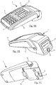
- the figure 1 represents an electronic payment terminal 1 which comprises in particular a keyboard 11, a screen 12 and a smart card reader 13 allowing the use of a payment card.
- a keyboard 11 a keyboard 11
- a screen 12 a smart card reader 13
- a box 10 which is itself composed of an upper half-shell 2 assembled on a lower half-shell 3.
- Figure 2 shows the electronic payment terminal 1 whose housing 10 is disassembled.
- the upper half-shell 2 and the lower half-shell 3 are thus separated, which allows access to the internal electronic components.
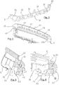
- complementary hinge elements are provided at a first end 31 of the lower shell 3 and at a first end 21. of the upper shell 2. Furthermore, locking elements are provided at a second end 32, opposite the first end 31, of the lower shell 3 and the second end 22, opposite the first end 21, of the hull. superior 2.
- the Figures 3 and 4 show respectively the first end 31 of the lower shell 3 and the first end 21 of the upper shell 2.
- the first end 31 of the lower shell 3 has an end wall carrying, on its outer surface, a series of tongues, or tenons 32.
- the first end 21 of the upper shell 2 also has an end wall which has, on its inner surface, a series of grooves 22, forming particular receiving orifices adapted to receive the hold 32.
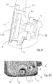
- the figure 5 represents, in sectional view, the first end 21 of the upper half-shell and the first end 31 of the lower half-shell.
- each of the tongues 32 is provided to fit into a corresponding groove 22.
- the set of tongues 32 and grooves 22 can thus form a hinge between the upper half-shell 2 and the lower half-shell 3.
- the respective shapes of the tenons 32 and grooves 22 are indeed chosen to allow a rotation of a half-shell relative to the other, about an axis corresponding to the longitudinal direction of the tenons, when the tenons 32 are inserted into the grooves 22.
- the lateral edges of the upper half-shell 2 also have, near the first end 21 of this half-shell, abutments 23, which are provided to cooperate with abutment portions 33 provided on the lateral edges of the half-shell. 3. These abutments cooperate with each other to allow insertion of the tongues 32 into the grooves 22, or the removal of the tongues 32 from the grooves 22, only when the upper and lower half-shells 3 form an angle between them. big enough. Once the tabs 32 introduced into the grooves 22, it is possible to vary this angle by rotation around the hinge formed by the tongues and grooves. This rotation is represented by the arrow 9 of the figure 5 .
- the figure 7 represents the second end 22 of the upper half-shell 2 and the second end 32 of the lower half-shell 3. These second ends are opposite the first ends of the half-shells.
- the upper half-shell 2 carries, at its second end 22, a locking ring 24, and the lower half-shell 3 carries, at its second end 32, a locking ring 34.
- the cylindrical opening formed by these rings extends along an axis directed substantially towards the hinge formed at the first ends of the upper half-shell and the lower half-shell. Consequently, the introduction of an anchor 4 in this cylindrical opening makes it possible, by holding the two rings 24 and 34 concentric, to block the rotation of one half-shell relative to the other, around the hinge formed in the level of the first ends of these half-shells. Locking the position of this single pin 4 then effectively locks the closure of the housing constituted by the half-shells 2 and 3.
- the sensitive components of the terminal are grouped close to this first end.
- these components are grouped in an enclosure located near the memory card reader, the chip card introduction form is located at the first end of the upper half-shell. Access to these sensitive components located near the axis of rotation therefore requires a large opening angle. Such an opening angle can easily be detected by an appropriate device, capable of triggering the shutdown of the terminal.
- the pin 4 which is inserted into the two rings 24 and 34 to lock the assembly of the housing has an axial opening 41 allowing the introduction of a screw 5. This screw 5 allows the fixing of the pin 4 to the housing 10.
- a counterbore 42 is also provided in the pin 4, so as to allow the introduction of a seal, or control seal 6 above the flat surface of the head of the screw 5.
- This control seal 6, which allows to attest that the integrity of the terminal has not been violated may for example be made of lead and be introduced by striking in the countersink 42. During the striking, the lead of the seal 6 can be introduced into a groove internal 420 provided in the countersink 42, which ensures its effective maintenance in the countersink 42. It is thus impossible, without destroying this seal, to unscrew the screw 5 and consequently to remove the pin 4 now assembled the two half-shells forming the housing 10.
- the lower half-shell 3 has a shape providing a bearing surface 34, in alignment with the axis of the pin 4, substantially perpendicular to this axis , and close to this ankle.
- This bearing surface 34 supports the housing 10 on an anvil adapted to perform the hitting of the seal 6 without the risk of damaging the terminal.
- the locking of the housing is provided by the pin 4 of circular section introduced into the openings of the wall elements of the half-shells, which form the locking rings.
- those skilled in the art can provide in the wall elements of the two half-shells openings of different shape (for example square openings), into which is introduced a dowel of adapted shape (for example of section square.
Landscapes
- Physics & Mathematics (AREA)
- General Physics & Mathematics (AREA)
- Casings For Electric Apparatus (AREA)
- Pivots And Pivotal Connections (AREA)
- Telephone Set Structure (AREA)
Claims (5)
- Elektronisches Zahlungsendgerät (1), umfassend ein Gehäuse (10), das aus zwei Halbschalen (2, 3) besteht, von denen eine den oberen Teil des Gehäuses und die andere den unteren Teil des Gehäuses bildet, wobei jede der Halbschalen (2, 3) komplementäre Scharnierelemente aufweist, die den schwenkbare Zusammenbau der beiden Halbschalen ermögliche, wobei die Halbschalen (2, 3) ferner komplementäre Anschläge (23, 33) aufweisen, die zusammenwirken, um den schwenkbaren Zusammenbau oder ein Auseinanderfallen des schwenkbaren Zusammenbaus zu verhindern, wenn die beiden Halbschalen zwischen sich einen Winkel unter 25° bilden, wobei das Gehäuse (10) Mittel (4) zum Blockieren des Schwenkens einer Halbschale in Bezug zur anderen in einer Verschlussposition des Gehäuses (10), in der die beiden Halbschalen (2, 3) übereinander angeordnet sind, umfassen.
- Elektronisches Zahlungsendgerät nach Anspruch 1, dadurch gekennzeichnet, dass die Scharnierelemente einer ersten der Halbschalen mindestens einen Zapfen (32) umfassen, und die Scharnierelemente der zweiten der Halbschalen mindestens eine Nut (22) umfassen, die geeignet ist, den Zapfen (32) aufzunehmen, wobei die jeweiligen Formen des Zapfens und der Nut derart gewählt sind, dass sie die Drehung des Zapfens in der Nut ermöglichen.
- Elektronisches Zahlungsendgerät nach Anspruch 2, dadurch gekennzeichnet, dass die Anschlagmittel (23, 33) zusammenwirken, um das Einsetzen des oder der Zapfen(s) (32) in die Nut(en) (22) oder das Austreten des oder der Zapfen (s) (32) aus der oder den Nut (en) (22) in der Verschlussposition des Gehäuses (10), in der die beiden Halbschalen (2, 3) übereinander angeordnet sind, zu verhindern.
- Elektronisches Zahlungsendgerät nach einem der vorhergehenden Ansprüche, dadurch gekennzeichnet, dass die Scharnierelemente in der Nähe eines ersten Endes (21, 31) jeder der Halbschalen (2, 3) angeordnet sind, und die Mittel zum Blockieren des Schwenkens in der Nähe eines zweiten Endes (22, 32) jeder der Halbschalen (2, 3), entgegengesetzt zu ersten Ende, angeordnet sind.
- Verfahren zum Zusammenbau des Gehäuses (10) eines elektronischen Zahlungsendgeräts (1), bestehend aus zwei Halbschalen (2, 3), wobei die beiden Halbschalen ferner komplementäre Anschläge (23, 33) umfassen, dadurch gekennzeichnet, dass es, wenn die beiden Halbschalen zwischen sich einen anfänglichen Winkel größer als 25° bilden, umfasst:- einen Schritt des Zusammenbaus von komplementären Scharnierelementen, die auf den beiden Halbschalen (2, 3) vorgesehen sind;- das Schwenken einer Halbschale in Bezug zu einer anderen um das Scharnier bis in eine Zusammenbauposition;- das Verriegeln der Drehung einer Halbschale in Bezug zu der anderen.
Priority Applications (1)
| Application Number | Priority Date | Filing Date | Title |
|---|---|---|---|
| PL14176226T PL2824619T3 (pl) | 2013-07-12 | 2014-07-09 | Terminal do płatności elektronicznych o ulepszonej obudowie |
Applications Claiming Priority (1)
| Application Number | Priority Date | Filing Date | Title |
|---|---|---|---|
| FR1356906A FR3008527B1 (fr) | 2013-07-12 | 2013-07-12 | Terminal de paiement electronique comprenant un boitier ameliore. |
Publications (3)
| Publication Number | Publication Date |
|---|---|
| EP2824619A2 EP2824619A2 (de) | 2015-01-14 |
| EP2824619A3 EP2824619A3 (de) | 2015-03-04 |
| EP2824619B1 true EP2824619B1 (de) | 2017-09-06 |
Family
ID=49546534
Family Applications (1)
| Application Number | Title | Priority Date | Filing Date |
|---|---|---|---|
| EP14176226.0A Active EP2824619B1 (de) | 2013-07-12 | 2014-07-09 | Elektronisches Zahlungsendgerät, das ein verbessertes Gehäuse umfasst |
Country Status (4)
| Country | Link |
|---|---|
| EP (1) | EP2824619B1 (de) |
| ES (1) | ES2650494T3 (de) |
| FR (1) | FR3008527B1 (de) |
| PL (1) | PL2824619T3 (de) |
Cited By (1)
| Publication number | Priority date | Publication date | Assignee | Title |
|---|---|---|---|---|
| US11978327B2 (en) | 2020-04-10 | 2024-05-07 | Banks And Acquirers International Holding | Electronic payment device with means for blocking access to a data storage module |
Family Cites Families (3)
| Publication number | Priority date | Publication date | Assignee | Title |
|---|---|---|---|---|
| FR2614169B1 (fr) * | 1987-04-14 | 1996-01-05 | Mang Ets Gerard | Boitier pour petit appareil electrique |
| FR2810018B1 (fr) * | 2000-06-09 | 2004-05-28 | Dassault Automatismes | Dispositif de fermeture sans vis d'un terminal de paiement electronique |
| FR2860643B1 (fr) * | 2003-10-07 | 2006-02-17 | Thales Sa | Dispositif anti-intrusion notamment pour terminal de paiement electronique |
-
2013
- 2013-07-12 FR FR1356906A patent/FR3008527B1/fr active Active
-
2014
- 2014-07-09 EP EP14176226.0A patent/EP2824619B1/de active Active
- 2014-07-09 ES ES14176226.0T patent/ES2650494T3/es active Active
- 2014-07-09 PL PL14176226T patent/PL2824619T3/pl unknown
Non-Patent Citations (1)
| Title |
|---|
| None * |
Cited By (1)
| Publication number | Priority date | Publication date | Assignee | Title |
|---|---|---|---|---|
| US11978327B2 (en) | 2020-04-10 | 2024-05-07 | Banks And Acquirers International Holding | Electronic payment device with means for blocking access to a data storage module |
Also Published As
| Publication number | Publication date |
|---|---|
| ES2650494T3 (es) | 2018-01-18 |
| EP2824619A3 (de) | 2015-03-04 |
| FR3008527B1 (fr) | 2018-01-05 |
| FR3008527A1 (fr) | 2015-01-16 |
| PL2824619T3 (pl) | 2018-03-30 |
| EP2824619A2 (de) | 2015-01-14 |
Similar Documents
| Publication | Publication Date | Title |
|---|---|---|
| FR2609565A1 (fr) | Carte d'acces et element a inserer pour cette carte | |
| FR2719866A3 (fr) | Boîte de protection contre le vol à l'étalage, dotée d'un système de fermeture compact et pouvant être ouverte par action magnétique. | |
| EP2824619B1 (de) | Elektronisches Zahlungsendgerät, das ein verbessertes Gehäuse umfasst | |
| BE1017300A7 (fr) | Perfectionnements introduits dans les systemes de connexion par interverrouillage applicables aux dispositifs electriques. | |
| EP2824620B1 (de) | Elektronisches Zahlungsendgerät, das ein verbessertes Verriegelungssystem des Gehäuses umfasst | |
| EP2926292A1 (de) | Klappe für endgerät | |
| FR2775377A1 (fr) | Boitier pour clavier a touches pour assurer la confidentialite | |
| EP4133440B1 (de) | Elektronische bezahlvorrichtung mit mitteln zur zugriffsblockierung auf ein datenspeichermodul | |
| FR2998984A1 (fr) | Boitier de terminal | |
| EP0952566B1 (de) | Plombierte Kappe zur Abdeckung eines Gegenstandes | |
| EP2824605B1 (de) | Vorrichtung zur elektronischen Bezahlung, die Zugangsblockiermittel zum Alibispeicher umfasst | |
| EP2824623B1 (de) | Zahlungsendgerät, das integrierte Registrierkassenfunktionen hat | |
| EP3585961B1 (de) | Gehäuse mit schieber zur verriegelung und immobilisierung in einer geschlossenen oder offenen position | |
| FR3014637A1 (fr) | Boitier pour au moins une carte electronique | |
| FR2581033A1 (fr) | Emballage en carton, carton ondule ou autre materiau en feuille, et son dispositif de verrouillage | |
| EP3097510B1 (de) | Magnetkopf für zahlungsterminal | |
| EP2824621B1 (de) | Elektronisches Zahlungsterminal | |
| EP3311328B1 (de) | Komponente zum halten eines magnetlesekopfs | |
| FR2499387A1 (fr) | Dispositif de presentation d'un article quelconque et article equipe d'un tel dispositif | |
| EP3050457B1 (de) | Schutz- und Schmuckvorrichtung | |
| FR2746534A1 (fr) | Systeme de badge | |
| FR2847733A1 (fr) | Appareillage electrique pourvu d'un dispositif antivol | |
| FR3017020A1 (fr) | Socle de fixation pour camera de surveillance et organe de fixation complementaire associe. | |
| FR2842954A1 (fr) | Enveloppe pour compteur elecrique monte sur un tableau inviolable | |
| EP3877967A1 (de) | Visueller anzeigeträger und entsprechende zahlungsvorrichtung |
Legal Events
| Date | Code | Title | Description |
|---|---|---|---|
| 17P | Request for examination filed |
Effective date: 20140709 |
|
| AK | Designated contracting states |
Kind code of ref document: A2 Designated state(s): AL AT BE BG CH CY CZ DE DK EE ES FI FR GB GR HR HU IE IS IT LI LT LU LV MC MK MT NL NO PL PT RO RS SE SI SK SM TR |
|
| AX | Request for extension of the european patent |
Extension state: BA ME |
|
| PUAI | Public reference made under article 153(3) epc to a published international application that has entered the european phase |
Free format text: ORIGINAL CODE: 0009012 |
|
| PUAL | Search report despatched |
Free format text: ORIGINAL CODE: 0009013 |
|
| AK | Designated contracting states |
Kind code of ref document: A3 Designated state(s): AL AT BE BG CH CY CZ DE DK EE ES FI FR GB GR HR HU IE IS IT LI LT LU LV MC MK MT NL NO PL PT RO RS SE SI SK SM TR |
|
| AX | Request for extension of the european patent |
Extension state: BA ME |
|
| RIC1 | Information provided on ipc code assigned before grant |
Ipc: H05K 5/00 20060101ALI20150127BHEP Ipc: G07G 1/12 20060101ALI20150127BHEP Ipc: G06Q 20/00 20120101AFI20150127BHEP Ipc: G07G 1/00 20060101ALI20150127BHEP Ipc: B65D 55/06 20060101ALI20150127BHEP |
|
| R17P | Request for examination filed (corrected) |
Effective date: 20150828 |
|
| RBV | Designated contracting states (corrected) |
Designated state(s): AL AT BE BG CH CY CZ DE DK EE ES FI FR GB GR HR HU IE IS IT LI LT LU LV MC MK MT NL NO PL PT RO RS SE SI SK SM TR |
|
| RAP1 | Party data changed (applicant data changed or rights of an application transferred) |
Owner name: INGENICO GROUP |
|
| GRAP | Despatch of communication of intention to grant a patent |
Free format text: ORIGINAL CODE: EPIDOSNIGR1 |
|
| INTG | Intention to grant announced |
Effective date: 20170303 |
|
| GRAS | Grant fee paid |
Free format text: ORIGINAL CODE: EPIDOSNIGR3 |
|
| GRAA | (expected) grant |
Free format text: ORIGINAL CODE: 0009210 |
|
| AK | Designated contracting states |
Kind code of ref document: B1 Designated state(s): AL AT BE BG CH CY CZ DE DK EE ES FI FR GB GR HR HU IE IS IT LI LT LU LV MC MK MT NL NO PL PT RO RS SE SI SK SM TR |
|
| REG | Reference to a national code |
Ref country code: GB Ref legal event code: FG4D Free format text: NOT ENGLISH |
|
| REG | Reference to a national code |
Ref country code: CH Ref legal event code: EP Ref country code: AT Ref legal event code: REF Ref document number: 926607 Country of ref document: AT Kind code of ref document: T Effective date: 20170915 |
|
| REG | Reference to a national code |
Ref country code: IE Ref legal event code: FG4D Free format text: LANGUAGE OF EP DOCUMENT: FRENCH |
|
| REG | Reference to a national code |
Ref country code: DE Ref legal event code: R096 Ref document number: 602014014059 Country of ref document: DE |
|
| REG | Reference to a national code |
Ref country code: NL Ref legal event code: MP Effective date: 20170906 |
|
| REG | Reference to a national code |
Ref country code: ES Ref legal event code: FG2A Ref document number: 2650494 Country of ref document: ES Kind code of ref document: T3 Effective date: 20180118 |
|
| REG | Reference to a national code |
Ref country code: LT Ref legal event code: MG4D |
|
| PG25 | Lapsed in a contracting state [announced via postgrant information from national office to epo] |
Ref country code: LT Free format text: LAPSE BECAUSE OF FAILURE TO SUBMIT A TRANSLATION OF THE DESCRIPTION OR TO PAY THE FEE WITHIN THE PRESCRIBED TIME-LIMIT Effective date: 20170906 Ref country code: SE Free format text: LAPSE BECAUSE OF FAILURE TO SUBMIT A TRANSLATION OF THE DESCRIPTION OR TO PAY THE FEE WITHIN THE PRESCRIBED TIME-LIMIT Effective date: 20170906 Ref country code: NO Free format text: LAPSE BECAUSE OF FAILURE TO SUBMIT A TRANSLATION OF THE DESCRIPTION OR TO PAY THE FEE WITHIN THE PRESCRIBED TIME-LIMIT Effective date: 20171206 Ref country code: FI Free format text: LAPSE BECAUSE OF FAILURE TO SUBMIT A TRANSLATION OF THE DESCRIPTION OR TO PAY THE FEE WITHIN THE PRESCRIBED TIME-LIMIT Effective date: 20170906 Ref country code: HR Free format text: LAPSE BECAUSE OF FAILURE TO SUBMIT A TRANSLATION OF THE DESCRIPTION OR TO PAY THE FEE WITHIN THE PRESCRIBED TIME-LIMIT Effective date: 20170906 |
|
| REG | Reference to a national code |
Ref country code: AT Ref legal event code: MK05 Ref document number: 926607 Country of ref document: AT Kind code of ref document: T Effective date: 20170906 |
|
| PG25 | Lapsed in a contracting state [announced via postgrant information from national office to epo] |
Ref country code: LV Free format text: LAPSE BECAUSE OF FAILURE TO SUBMIT A TRANSLATION OF THE DESCRIPTION OR TO PAY THE FEE WITHIN THE PRESCRIBED TIME-LIMIT Effective date: 20170906 Ref country code: RS Free format text: LAPSE BECAUSE OF FAILURE TO SUBMIT A TRANSLATION OF THE DESCRIPTION OR TO PAY THE FEE WITHIN THE PRESCRIBED TIME-LIMIT Effective date: 20170906 Ref country code: BG Free format text: LAPSE BECAUSE OF FAILURE TO SUBMIT A TRANSLATION OF THE DESCRIPTION OR TO PAY THE FEE WITHIN THE PRESCRIBED TIME-LIMIT Effective date: 20171206 |
|
| PG25 | Lapsed in a contracting state [announced via postgrant information from national office to epo] |
Ref country code: NL Free format text: LAPSE BECAUSE OF FAILURE TO SUBMIT A TRANSLATION OF THE DESCRIPTION OR TO PAY THE FEE WITHIN THE PRESCRIBED TIME-LIMIT Effective date: 20170906 |
|
| PG25 | Lapsed in a contracting state [announced via postgrant information from national office to epo] |
Ref country code: RO Free format text: LAPSE BECAUSE OF FAILURE TO SUBMIT A TRANSLATION OF THE DESCRIPTION OR TO PAY THE FEE WITHIN THE PRESCRIBED TIME-LIMIT Effective date: 20170906 Ref country code: CZ Free format text: LAPSE BECAUSE OF FAILURE TO SUBMIT A TRANSLATION OF THE DESCRIPTION OR TO PAY THE FEE WITHIN THE PRESCRIBED TIME-LIMIT Effective date: 20170906 |
|
| REG | Reference to a national code |
Ref country code: GR Ref legal event code: EP Ref document number: 20170403333 Country of ref document: GR Effective date: 20180420 |
|
| PG25 | Lapsed in a contracting state [announced via postgrant information from national office to epo] |
Ref country code: AT Free format text: LAPSE BECAUSE OF FAILURE TO SUBMIT A TRANSLATION OF THE DESCRIPTION OR TO PAY THE FEE WITHIN THE PRESCRIBED TIME-LIMIT Effective date: 20170906 Ref country code: IS Free format text: LAPSE BECAUSE OF FAILURE TO SUBMIT A TRANSLATION OF THE DESCRIPTION OR TO PAY THE FEE WITHIN THE PRESCRIBED TIME-LIMIT Effective date: 20180106 Ref country code: EE Free format text: LAPSE BECAUSE OF FAILURE TO SUBMIT A TRANSLATION OF THE DESCRIPTION OR TO PAY THE FEE WITHIN THE PRESCRIBED TIME-LIMIT Effective date: 20170906 Ref country code: SK Free format text: LAPSE BECAUSE OF FAILURE TO SUBMIT A TRANSLATION OF THE DESCRIPTION OR TO PAY THE FEE WITHIN THE PRESCRIBED TIME-LIMIT Effective date: 20170906 Ref country code: SM Free format text: LAPSE BECAUSE OF FAILURE TO SUBMIT A TRANSLATION OF THE DESCRIPTION OR TO PAY THE FEE WITHIN THE PRESCRIBED TIME-LIMIT Effective date: 20170906 |
|
| REG | Reference to a national code |
Ref country code: DE Ref legal event code: R097 Ref document number: 602014014059 Country of ref document: DE |
|
| PLBE | No opposition filed within time limit |
Free format text: ORIGINAL CODE: 0009261 |
|
| STAA | Information on the status of an ep patent application or granted ep patent |
Free format text: STATUS: NO OPPOSITION FILED WITHIN TIME LIMIT |
|
| REG | Reference to a national code |
Ref country code: FR Ref legal event code: PLFP Year of fee payment: 5 |
|
| PG25 | Lapsed in a contracting state [announced via postgrant information from national office to epo] |
Ref country code: DK Free format text: LAPSE BECAUSE OF FAILURE TO SUBMIT A TRANSLATION OF THE DESCRIPTION OR TO PAY THE FEE WITHIN THE PRESCRIBED TIME-LIMIT Effective date: 20170906 |
|
| 26N | No opposition filed |
Effective date: 20180607 |
|
| PG25 | Lapsed in a contracting state [announced via postgrant information from national office to epo] |
Ref country code: SI Free format text: LAPSE BECAUSE OF FAILURE TO SUBMIT A TRANSLATION OF THE DESCRIPTION OR TO PAY THE FEE WITHIN THE PRESCRIBED TIME-LIMIT Effective date: 20170906 |
|
| PG25 | Lapsed in a contracting state [announced via postgrant information from national office to epo] |
Ref country code: MT Free format text: LAPSE BECAUSE OF FAILURE TO SUBMIT A TRANSLATION OF THE DESCRIPTION OR TO PAY THE FEE WITHIN THE PRESCRIBED TIME-LIMIT Effective date: 20170906 |
|
| REG | Reference to a national code |
Ref country code: CH Ref legal event code: PL |
|
| PG25 | Lapsed in a contracting state [announced via postgrant information from national office to epo] |
Ref country code: MC Free format text: LAPSE BECAUSE OF FAILURE TO SUBMIT A TRANSLATION OF THE DESCRIPTION OR TO PAY THE FEE WITHIN THE PRESCRIBED TIME-LIMIT Effective date: 20170906 Ref country code: LU Free format text: LAPSE BECAUSE OF NON-PAYMENT OF DUE FEES Effective date: 20180709 |
|
| REG | Reference to a national code |
Ref country code: BE Ref legal event code: MM Effective date: 20180731 |
|
| REG | Reference to a national code |
Ref country code: IE Ref legal event code: MM4A |
|
| PG25 | Lapsed in a contracting state [announced via postgrant information from national office to epo] |
Ref country code: CH Free format text: LAPSE BECAUSE OF NON-PAYMENT OF DUE FEES Effective date: 20180731 Ref country code: LI Free format text: LAPSE BECAUSE OF NON-PAYMENT OF DUE FEES Effective date: 20180731 Ref country code: IE Free format text: LAPSE BECAUSE OF NON-PAYMENT OF DUE FEES Effective date: 20180709 |
|
| PG25 | Lapsed in a contracting state [announced via postgrant information from national office to epo] |
Ref country code: BE Free format text: LAPSE BECAUSE OF NON-PAYMENT OF DUE FEES Effective date: 20180731 |
|
| PG25 | Lapsed in a contracting state [announced via postgrant information from national office to epo] |
Ref country code: TR Free format text: LAPSE BECAUSE OF FAILURE TO SUBMIT A TRANSLATION OF THE DESCRIPTION OR TO PAY THE FEE WITHIN THE PRESCRIBED TIME-LIMIT Effective date: 20170906 |
|
| PG25 | Lapsed in a contracting state [announced via postgrant information from national office to epo] |
Ref country code: HU Free format text: LAPSE BECAUSE OF FAILURE TO SUBMIT A TRANSLATION OF THE DESCRIPTION OR TO PAY THE FEE WITHIN THE PRESCRIBED TIME-LIMIT; INVALID AB INITIO Effective date: 20140709 Ref country code: PT Free format text: LAPSE BECAUSE OF FAILURE TO SUBMIT A TRANSLATION OF THE DESCRIPTION OR TO PAY THE FEE WITHIN THE PRESCRIBED TIME-LIMIT Effective date: 20170906 |
|
| PG25 | Lapsed in a contracting state [announced via postgrant information from national office to epo] |
Ref country code: MK Free format text: LAPSE BECAUSE OF NON-PAYMENT OF DUE FEES Effective date: 20170906 Ref country code: CY Free format text: LAPSE BECAUSE OF FAILURE TO SUBMIT A TRANSLATION OF THE DESCRIPTION OR TO PAY THE FEE WITHIN THE PRESCRIBED TIME-LIMIT Effective date: 20170906 |
|
| PG25 | Lapsed in a contracting state [announced via postgrant information from national office to epo] |
Ref country code: AL Free format text: LAPSE BECAUSE OF FAILURE TO SUBMIT A TRANSLATION OF THE DESCRIPTION OR TO PAY THE FEE WITHIN THE PRESCRIBED TIME-LIMIT Effective date: 20170906 |
|
| REG | Reference to a national code |
Ref country code: GB Ref legal event code: 732E Free format text: REGISTERED BETWEEN 20220127 AND 20220202 |
|
| REG | Reference to a national code |
Ref country code: DE Ref legal event code: R081 Ref document number: 602014014059 Country of ref document: DE Owner name: BANKS AND ACQUIRES INTERNATIONAL HOLDING, FR Free format text: FORMER OWNER: INGENICO GROUP, PARIS, FR Ref country code: DE Ref legal event code: R082 Ref document number: 602014014059 Country of ref document: DE Representative=s name: STUMPF PATENTANWAELTE PARTGMBB, DE Ref country code: DE Ref legal event code: R081 Ref document number: 602014014059 Country of ref document: DE Owner name: BANKS AND ACQUIRERS INTERNATIONAL HOLDING, FR Free format text: FORMER OWNER: INGENICO GROUP, PARIS, FR |
|
| REG | Reference to a national code |
Ref country code: DE Ref legal event code: R081 Ref document number: 602014014059 Country of ref document: DE Owner name: BANKS AND ACQUIRERS INTERNATIONAL HOLDING, FR Free format text: FORMER OWNER: BANKS AND ACQUIRES INTERNATIONAL HOLDING, SURESNES, FR |
|
| PGFP | Annual fee paid to national office [announced via postgrant information from national office to epo] |
Ref country code: PL Payment date: 20250626 Year of fee payment: 12 |
|
| REG | Reference to a national code |
Ref country code: ES Ref legal event code: PC2A Owner name: BANKS AND ACQUIRERS INTERNATIONAL HOLDING Effective date: 20250929 |
|
| PGFP | Annual fee paid to national office [announced via postgrant information from national office to epo] |
Ref country code: ES Payment date: 20250826 Year of fee payment: 12 |
|
| PGFP | Annual fee paid to national office [announced via postgrant information from national office to epo] |
Ref country code: DE Payment date: 20250722 Year of fee payment: 12 |
|
| PGFP | Annual fee paid to national office [announced via postgrant information from national office to epo] |
Ref country code: GR Payment date: 20250721 Year of fee payment: 12 |
|
| PGFP | Annual fee paid to national office [announced via postgrant information from national office to epo] |
Ref country code: IT Payment date: 20250724 Year of fee payment: 12 |
|
| PGFP | Annual fee paid to national office [announced via postgrant information from national office to epo] |
Ref country code: GB Payment date: 20250722 Year of fee payment: 12 |
|
| PGFP | Annual fee paid to national office [announced via postgrant information from national office to epo] |
Ref country code: FR Payment date: 20250730 Year of fee payment: 12 |
|
| P01 | Opt-out of the competence of the unified patent court (upc) registered |
Free format text: CASE NUMBER: UPC_APP_0000324_2824619/2026 Effective date: 20260106 |