EP2824533B1 - Système photovoltaïque - Google Patents
Système photovoltaïque Download PDFInfo
- Publication number
- EP2824533B1 EP2824533B1 EP14175412.7A EP14175412A EP2824533B1 EP 2824533 B1 EP2824533 B1 EP 2824533B1 EP 14175412 A EP14175412 A EP 14175412A EP 2824533 B1 EP2824533 B1 EP 2824533B1
- Authority
- EP
- European Patent Office
- Prior art keywords
- power
- output
- voltage
- controller
- sensed current
- Prior art date
- Legal status (The legal status is an assumption and is not a legal conclusion. Google has not performed a legal analysis and makes no representation as to the accuracy of the status listed.)
- Active
Links
- 230000003247 decreasing effect Effects 0.000 claims description 13
- 230000005611 electricity Effects 0.000 claims description 3
- 239000000428 dust Substances 0.000 description 6
- 238000000034 method Methods 0.000 description 6
- 229920001296 polysiloxane Polymers 0.000 description 5
- 239000004065 semiconductor Substances 0.000 description 4
- 101000802640 Homo sapiens Lactosylceramide 4-alpha-galactosyltransferase Proteins 0.000 description 3
- 102100035838 Lactosylceramide 4-alpha-galactosyltransferase Human genes 0.000 description 3
- 238000010586 diagram Methods 0.000 description 3
- 230000007423 decrease Effects 0.000 description 2
- 230000002265 prevention Effects 0.000 description 2
- XUIMIQQOPSSXEZ-UHFFFAOYSA-N Silicon Chemical compound [Si] XUIMIQQOPSSXEZ-UHFFFAOYSA-N 0.000 description 1
- 239000003990 capacitor Substances 0.000 description 1
- 150000001875 compounds Chemical class 0.000 description 1
- 230000007257 malfunction Effects 0.000 description 1
- 238000012986 modification Methods 0.000 description 1
- 230000004048 modification Effects 0.000 description 1
- 229910052710 silicon Inorganic materials 0.000 description 1
- 239000010703 silicon Substances 0.000 description 1
Images


Classifications
-
- H—ELECTRICITY
- H10—SEMICONDUCTOR DEVICES; ELECTRIC SOLID-STATE DEVICES NOT OTHERWISE PROVIDED FOR
- H10F—INORGANIC SEMICONDUCTOR DEVICES SENSITIVE TO INFRARED RADIATION, LIGHT, ELECTROMAGNETIC RADIATION OF SHORTER WAVELENGTH OR CORPUSCULAR RADIATION
- H10F77/00—Constructional details of devices covered by this subclass
- H10F77/95—Circuit arrangements
- H10F77/953—Circuit arrangements for devices having potential barriers
- H10F77/955—Circuit arrangements for devices having potential barriers for photovoltaic devices
-
- G—PHYSICS
- G05—CONTROLLING; REGULATING
- G05F—SYSTEMS FOR REGULATING ELECTRIC OR MAGNETIC VARIABLES
- G05F1/00—Automatic systems in which deviations of an electric quantity from one or more predetermined values are detected at the output of the system and fed back to a device within the system to restore the detected quantity to its predetermined value or values, i.e. retroactive systems
- G05F1/66—Regulating electric power
- G05F1/67—Regulating electric power to the maximum power available from a generator, e.g. from solar cell
-
- H—ELECTRICITY
- H02—GENERATION; CONVERSION OR DISTRIBUTION OF ELECTRIC POWER
- H02S—GENERATION OF ELECTRIC POWER BY CONVERSION OF INFRARED RADIATION, VISIBLE LIGHT OR ULTRAVIOLET LIGHT, e.g. USING PHOTOVOLTAIC [PV] MODULES
- H02S40/00—Components or accessories in combination with PV modules, not provided for in groups H02S10/00 - H02S30/00
- H02S40/30—Electrical components
- H02S40/32—Electrical components comprising DC/AC inverter means associated with the PV module itself, e.g. AC modules
-
- H—ELECTRICITY
- H02—GENERATION; CONVERSION OR DISTRIBUTION OF ELECTRIC POWER
- H02S—GENERATION OF ELECTRIC POWER BY CONVERSION OF INFRARED RADIATION, VISIBLE LIGHT OR ULTRAVIOLET LIGHT, e.g. USING PHOTOVOLTAIC [PV] MODULES
- H02S50/00—Monitoring or testing of PV systems, e.g. load balancing or fault identification
-
- Y—GENERAL TAGGING OF NEW TECHNOLOGICAL DEVELOPMENTS; GENERAL TAGGING OF CROSS-SECTIONAL TECHNOLOGIES SPANNING OVER SEVERAL SECTIONS OF THE IPC; TECHNICAL SUBJECTS COVERED BY FORMER USPC CROSS-REFERENCE ART COLLECTIONS [XRACs] AND DIGESTS
- Y02—TECHNOLOGIES OR APPLICATIONS FOR MITIGATION OR ADAPTATION AGAINST CLIMATE CHANGE
- Y02E—REDUCTION OF GREENHOUSE GAS [GHG] EMISSIONS, RELATED TO ENERGY GENERATION, TRANSMISSION OR DISTRIBUTION
- Y02E10/00—Energy generation through renewable energy sources
- Y02E10/50—Photovoltaic [PV] energy
- Y02E10/56—Power conversion systems, e.g. maximum power point trackers
Definitions
- the present disclosure relates to a photovoltaic system, and particularly, to a photovoltaic system including a power optimizer, capable of minimizing noise occurring while a maximum power point tracking (MPPT) algorithm is performed, due to shading, an error in an output power of a photovoltaic module, etc.
- MPPT maximum power point tracking
- a photovoltaic system includes a plurality of photovoltaic modules connected to each other in series, and an inverter configured to convert a DC voltage output from the plurality of photovoltaic modules into an AC voltage, and configured to output the AC power.
- Prior art photovoltaic systems are disclosed in US 2009/284240 , WO 2010/087804 and EP 2 503 426 .
- the conventional photovoltaic system may have the following problems.
- an inverter positioned at the next stage of the photovoltaic modules may be damaged.
- an aspect of the detailed description is to provide a photovoltaic system capable of minimizing noise occurring while a maximum power point tracking (MPPT) algorithm is performed, by bypassing one or more photovoltaic modules among a plurality of photovoltaic modules serially-connected to each other, in a case where the corresponding photovoltaic module has a significant change in the amount of sunshine, i.e., in a case where an output current of the corresponding photovoltaic module is significantly decreased due to wind, rain, dust in the air, shading, etc.
- a present output current and a previous output current of the corresponding photovoltaic module are compared with each other. Then if a difference between the present output current and the previous output current exceeds a preset reference value, the corresponding photovoltaic module is bypassed.
- photovoltaic system as defined in independent claim 1, comprising: a plurality of photovoltaic modules implemented in a string, and configured to output a generated power; a power optimizer serially-connected to each of the photovoltaic modules, configured to sense an output voltage and an output current of each of the photovoltaic modules, and to compare the presently-sensed current with a previously-sensed current, to thus control the output voltage; and an inverter configured to convert the output voltage of a DC form into an AC voltage.
- the power optimizer may stop the MPPT algorithm, and may operate the bypass unit included therein such that an output of the power optimizer can be bypassed.
- the power optimizer may search for a maximum power point based on the sensed voltage and current, by performing the MPPT algorithm. Then the power optimizer may determine an output voltage thereof, based on a maximum power corresponding to the searched maximum power point, and based on the sensed current, and may output the determined output voltage.
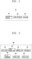
- FIG. 1 is a block diagram illustrating a configuration of a photovoltaic system 10 according to the present invention.
- the photovoltaic system 10 includes a photovoltaic module 100, a power optimizer 200 and an inverter 300.
- the present invention is not limited to the components of FIG. 1 . That is, the photovoltaic system 10 may include smaller or larger number of components than the components shown in FIG. 1 .
- the photovoltaic module 100 is formed in plurality, and the plurality of photovoltaic modules 100 are formed in series (or are implemented in a string).
- the photovoltaic modules 100 generate electricity from solar light, and transmit the generated electricity to the power optimizer 200 connected thereto.
- the photovoltaic modules 100 are implemented as solar cells which include silicon semiconductor devices formed of silicone such as amorphous silicone, microcrystalline silicone, crystalline silicone and mono-crystalline silicone, compound semiconductor devices, etc.
- the power optimizer 200 is composed of an input unit 210, a power supply unit 220, a sensing unit 230, a controller 240, a DC-DC converter 250, a bypass unit 260 and an output unit 270.
- the present invention is not limited to the components of FIG. 2 . That is, the power optimizer 200 may include smaller or larger number of components than the components of FIG. 2 .
- the input unit 210 receives an output power (or voltage/current) of the photovoltaic module 100.
- the input unit 210 includes a device (not shown) for removing noise included in the received power.
- the power supply unit 220 converts the voltage received by the input unit 210, into a voltage proper to the components included in the power optimizer 200. Then the power supply unit 220 supplies the converted voltage, to the components included in the power optimizer 200.
- the power supply unit 220 is composed of a buck converter, a plurality of semiconductor devices, etc.
- the sensing unit (or measuring unit) 230 is operated under control of the controller 240, and is configured to sense (or measure) a current and a voltage input from the photovoltaic module 100.
- the controller 240 entirely controls the power optimizer 200.
- the controller 240 determines whether a difference between the presently-sensed current and a previously-sensed current exceeds a preset reference value.
- the controller 240 checks whether a difference between the presently-sensed current and a previously-sensed current exceeds a preset reference value (e.g., 5A).
- a preset reference value e.g., 5A
- the controller 240 operates the bypass unit 260, thereby bypassing an output power of a corresponding photovoltaic module 100 connected to the power optimizer 200, among the plurality of photovoltaic modules 100 implemented in a string.
- the controller 240 may operate the bypass unit 260, thereby bypassing an output power of the power optimizer 200 connected to the corresponding photovoltaic module 100.
- the controller 240 determines that an output current of the corresponding photovoltaic module 100 has been drastically decreased due to wind, rain, dust in the air, shading, etc. As a result, the controller 240 may operate the bypass unit 260 of the power optimizer 200 connected to the corresponding photovoltaic module 100, or may bypass an output (output power) of the power optimizer 200, for prevention of an output of the corresponding photovoltaic module 100 among the plurality of photovoltaic modules 100 serially-connected to each other.
- the preset reference value e.g., 5A
- the controller 240 periodically increases or decreases the presently-sensed voltage (or output voltage of the photovoltaic module 100) based on the presently-sensed current and voltage. And the controller 240 performs a Maximum Power Point Tracking (MPPT) or a Perturbation and Observation Maximum Power Point Tracking (P&O MPPT) algorithm, through a comparison between a previous output power and a present output power, thereby searching for (tracking) a maximum power point.
- MPPT Maximum Power Point Tracking
- P&O MPPT Perturbation and Observation Maximum Power Point Tracking
- the controller 240 calculates power based on the currently-sensed voltage and current (S310).
- the controller 240 compares present power (e.g., P(k)) with previous power (e.g., P(k-1)), thereby determining whether the present power (P(k)) has been increased or decreased with respect to the previous power (P(k-1)) (S320).
- present power e.g., P(k)
- previous power e.g., P(k-1)
- the controller 240 compares a present voltage (e.g., V(k)) with a previous voltage (e.g., V(k-1)), thereby determining whether the present voltage (V(k)) has been increased or decreased with respect to the previous voltage (V(k-1)) (S330, S340).
- a present voltage e.g., V(k)
- a previous voltage e.g., V(k-1)
- a voltage reference value (e.g., Vref) of the photovoltaic module 100 is increased by a preset value (e.g., ⁇ V ) (S350). If the present power has been deceased with respect to the previous power while the present voltage has been increased with respect to the previous voltage, the voltage reference value (e.g., Vref) of the photovoltaic module 100 is decreased by the preset value (e.g., ⁇ V ) (S360).
- the voltage reference value (e.g., Vref) of the photovoltaic module 100 is decreased by the preset value (e.g., ⁇ V ) (S370). If both the present power and the present voltage have been increased with respect to the previous power and the previous voltage, the voltage reference value (e.g., Vref) of the photovoltaic module 100 is increased by the preset value (e.g., ⁇ V ) (S380).
- the DC-DC converter 250 compares an input voltage with an output voltage, and is operated in a voltage lowering mode or a boosting mode based on a result of the comparison.
- the DC-DC converter 250 searches for a maximum power point (or the next voltage reference value) of the photovoltaic module.
- the controller 240 uses the voltage reference value of the photovoltaic module 100 as it is.
- the controller 240 determines an output voltage of the power optimizer 200, based on a maximum power corresponding to the searched maximum power point, and based on the sensed current.
- the controller 240 performs the MPPT algorithm as shown in a second graph 420 to thus search for the maximum power point. Then as shown in a third graph 430, the controller 240 determines an output voltage (or voltage reference value) of the power optimizer 200, through an output power and a string current. In this case, the output power is the same as (or similar to) an input power of the power optimizer 200.
- the controller 240 transmits (outputs) the determined output voltage of the power optimizer 200, to the inverter 300 through the output unit 270.
- the controller 240 searches for (tracks) a maximum power point input of the photovoltaic modules 100, and outputs the power input through the input unit 210 to the output unit 270.
- the DC-DC converter 250 lowers or boosts an input voltage of the power optimizer 200 by a prescribed voltage (or preset reference value), with respect to an output voltage of the of the power optimizer 200, while the MPPT algorithm is performed by the controller 240.
- the DC-DC converter 250 is composed of a semiconductor device and a capacitor which are for lowering a voltage or boosting.
- the bypass unit 260 is operated under control of the controller 240.
- the bypass unit 260 includes one or more bypass diodes.
- the bypass unit 260 stops the MPPT algorithm so that an operation of the rest 9 photovoltaic modules 100 cannot be influenced. At the same time, the bypass unit 260 bypasses an output of the power optimizer 200, thereby minimizing noise occurring from the output unit 270.
- the output unit 270 outputs the output voltage (voltage reference value) determined through the controller 240 and the DC-DC converter 250, to the inverter 300.
- the output unit 270 is composed of the same components as the input unit 210.
- the inverter (photovoltaic inverter) 300 converts a DC voltage received from the power optimizer 200 into an AC voltage, and then provides the AC voltage to a load (not shown).
- the controller compares a present output current of the corresponding photovoltaic module, with a previous output current of the corresponding photovoltaic module. If a difference between the two currents exceeds a preset reference value, the controller may bypass the corresponding photovoltaic module.
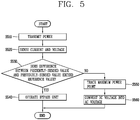
- FIG. 5 is a flowchart illustrating a method for controlling a photovoltaic system according to an embodiment of the present invention.
- a plurality of photovoltaic modules 100 connected to each other in series transmit generated power (or current/voltage) to a power optimizer 200 connected thereto (S510).
- the power optimizer 200 is operated by the current and the voltage received from the photovoltaic module, and sensing (measuring) the current and the voltage (S520).
- the power optimizer 200 determines whether a difference between the presently-sensed current and a previously-sensed current exceeds a preset reference value (S530).
- the power optimizer 200 determines whether a difference between the presently-sensed current and a previously-sensed current exceeds a preset reference value (e.g., 5A).
- a preset reference value e.g., 5A
- the power optimizer 200 operates a bypass unit 260 included therein, thereby bypassing an output power of the photovoltaic module 100 connected to the power optimizer 200, among the plurality of photovoltaic modules 100 implemented in a string.
- the power optimizer 200 may operate the bypass unit 260, thereby bypassing an output power of the power optimizer 200 connected to the corresponding photovoltaic module 100.
- the power optimizer 200 determines that an output current of the corresponding photovoltaic module 100 has been drastically decreased due to wind, rain, dust in the air, shading, etc. For prevention of an output of the corresponding photovoltaic module 100 among the plurality of photovoltaic modules 100 serially-connected to each other, the power optimizer 200 connected to the corresponding photovoltaic module 100 operates its bypass unit 260, the bypass unit 260 connected to the corresponding photovoltaic module 100. As a result, the power optimizer 200 bypasses an output (output power) of the power optimizer 200 (S540).
- the preset reference value e.g. 5A
- the power optimizer 200 periodically increases or decreases the sensed voltage, based on the sensed current.
- the power optimizer 200 searches for a maximum power point, by performing an MPPT (or P&O MPPT) algorithm.
- the power optimizer 200 determines an output voltage thereof, based on a maximum power corresponding to the searched maximum power point, and based on the sensed current.
- the power optimizer 200 transmits the determined output voltage thereof to the inverter 300 (S550).
- the inverter 300 converts a DC voltage received from the power optimizer 200 into an AC voltage, and then provides the AC voltage to a load (not shown) (S560).
- the photovoltaic system of the present invention can minimize noise occurring while a maximum power point tracking (MPPT) algorithm is performed, by bypassing one or more photovoltaic modules among a plurality of photovoltaic modules serially-connected to each other, in a case where the corresponding photovoltaic module has a significant change in the amount of sunshine, i.e., in a case where an output current of the corresponding photovoltaic module is significantly decreased due to wind, rain, dust in the air, shading, etc.
- a present output current and a previous output current of the corresponding photovoltaic module are compared with each other. Then if a difference between the present output current and the previous output current exceeds a preset reference value, the corresponding photovoltaic module is bypassed.
Landscapes
- Engineering & Computer Science (AREA)
- Life Sciences & Earth Sciences (AREA)
- Sustainable Development (AREA)
- Sustainable Energy (AREA)
- Electromagnetism (AREA)
- Physics & Mathematics (AREA)
- Power Engineering (AREA)
- General Physics & Mathematics (AREA)
- Radar, Positioning & Navigation (AREA)
- Automation & Control Theory (AREA)
- Control Of Electrical Variables (AREA)
- Inverter Devices (AREA)
- Photovoltaic Devices (AREA)
Claims (4)
- Système photovoltaïque (10), le système photovoltaïque (10) comprenant :une pluralité de modules photovoltaïques (100) configurés pour être connectés en série l'un à l'autre sur une branche ;un optimiseur de puissance (200) ; etun onduleur (300),caractérisé en ce que la pluralité de modules photovoltaïques (100) sont configurés pour transmettre une électricité générée à l'optimiseur de puissance (200) connecté à ceux-ci,l'optimiseur de puissance (200) comportant :une unité d'entrée (210) configurée pour recevoir une puissance de sortie de la pluralité de modules photovoltaïques (100) et éliminer un bruit inclus dans la puissance de sortie reçue par la pluralité de modules photovoltaïques (100) ;une unité de détection (230) configurée pour détecter une tension de sortie et un courant de sortie de la pluralité de modules photovoltaïques (100) ;un dispositif de commande (240) configuré pour commander une sortie de l'optimiseur de puissance (200), en exécutant un algorithme de recherche du point de puissance maximale, MPPT, et en comparant le courant en cours présentement détecté à un courant détecté antérieurementun convertisseur CC-CC (250) configuré pour abaisser ou amplifier une tension d'entrée de l'optimiseur de puissance (200) d'une valeur de référence prédéfinie, vis-à-vis d'une tension de sortie de l'optimiseur de puissance (200), tandis que l'algorithme MPPT est exécuté par le dispositif de commande (240) ;une unité de dérivation (260) configurée pour dériver une sortie de l'optimiseur de puissance (200) sous la commande du dispositif de commande (240) ;une unité de sortie (270) configurée pour fournir en sortie une sortie de l'optimiseur de puissance (200) à l'onduleur (300), etune unité d'alimentation (220) configurée pour convertir une tension de la puissance reçue par l'unité d'entrée (210), et alimenter l'unité de détection (230), le dispositif de commande (240), le convertisseur CC-CC (250), l'unité de dérivation (260) et l'unité de sortie (270) sur la base de la puissance reçue par l'unité d'entrée (210) ;dans lequel si un courant de sortie d'au moins l'un de la pluralité de modules photovoltaïques (100) est réduit, le dispositif de commande (240) est configuré pour déterminer si le courant présentement détecté est plus petit qu'un courant détecté antérieurement de plus d'une valeur de référence prédéfinie,dans lequel si le courant présentement détecté est plus petit que le courant détecté antérieurement de plus de la valeur de référence prédéfinie, le dispositif de commande (240) interrompt l'algorithme MPPT en cours d'exécution, et actionne l'unité de dérivation (260) de sorte que la sortie de l'optimiseur de puissance (200) est dérivée.
- Système photovoltaïque (10) selon la revendication 1, caractérisé en ce que si le courant présentement détecté n'est pas plus petit que le courant détecté antérieurement de plus de la valeur de référence prédéfinie, le dispositif de commande (240) recherche un point de puissance maximale sur la base de la tension et du courant détectés, en exécutant l'algorithme MPPT conjointement au convertisseur CC-CC (250), et détermine une tension de sortie de l'optimiseur de puissance (200) sur la base d'une puissance maximale correspondant au point de puissance maximale recherché, et sur la base du courant détecté.
- Système photovoltaïque (10) selon l'une quelconque des revendications 1 à 2, caractérisé en ce que si le courant présentement détecté n'est pas plus petit que le courant détecté antérieurement de plus de la valeur de référence prédéfinie, le dispositif de commande (240) recherche un point de puissance maximale sur la base de la tension et du courant détectés, en exécutant l'algorithme MPPT, détermine une tension correspondant à la puissance reçue par l'unité d'entrée (210) en tant que tension de sortie de l'optimiseur de puissance (200), et fournit en sortie la tension de sortie déterminée.
- Système photovoltaïque (10) selon l'une quelconque des revendications 1 à 3, caractérisé en ce que l'unité de dérivation (260) comporte une ou plusieurs diodes de dérivation.
Applications Claiming Priority (1)
| Application Number | Priority Date | Filing Date | Title |
|---|---|---|---|
| KR20130081154A KR101452776B1 (ko) | 2013-07-10 | 2013-07-10 | 태양광 시스템 |
Publications (3)
| Publication Number | Publication Date |
|---|---|
| EP2824533A2 EP2824533A2 (fr) | 2015-01-14 |
| EP2824533A3 EP2824533A3 (fr) | 2015-03-11 |
| EP2824533B1 true EP2824533B1 (fr) | 2020-04-08 |
Family
ID=51033047
Family Applications (1)
| Application Number | Title | Priority Date | Filing Date |
|---|---|---|---|
| EP14175412.7A Active EP2824533B1 (fr) | 2013-07-10 | 2014-07-02 | Système photovoltaïque |
Country Status (6)
| Country | Link |
|---|---|
| US (1) | US9583645B2 (fr) |
| EP (1) | EP2824533B1 (fr) |
| JP (1) | JP2015018555A (fr) |
| KR (1) | KR101452776B1 (fr) |
| CN (1) | CN104283504B (fr) |
| ES (1) | ES2799576T3 (fr) |
Families Citing this family (17)
| Publication number | Priority date | Publication date | Assignee | Title |
|---|---|---|---|---|
| US9105765B2 (en) | 2012-12-18 | 2015-08-11 | Enphase Energy, Inc. | Smart junction box for a photovoltaic system |
| KR101653788B1 (ko) | 2015-02-05 | 2016-09-05 | (주) 조인테크놀로지 | 전력생성장치 |
| WO2017087988A1 (fr) * | 2015-11-19 | 2017-05-26 | Beamreach Solar, Inc. | Système photovoltaïque solaire à optimisation de suivi de point de puissance maximal multimodal |
| CN105680793B (zh) * | 2016-03-23 | 2018-02-23 | 阳光电源股份有限公司 | 一种光伏系统的电压补偿装置及光伏系统 |
| CN106020329A (zh) * | 2016-07-27 | 2016-10-12 | 江苏南能电气有限公司 | 一种基于lora无线通信的光伏功率优化器及系统 |
| JP6658582B2 (ja) * | 2017-01-31 | 2020-03-04 | オムロン株式会社 | アーク検出装置 |
| JP6658586B2 (ja) * | 2017-02-03 | 2020-03-04 | オムロン株式会社 | アーク検出装置 |
| CN107248843B (zh) * | 2017-05-31 | 2019-04-05 | 华为技术有限公司 | 一种光伏发电的控制方法、控制设备及光伏发电系统 |
| CN107360646A (zh) * | 2017-07-14 | 2017-11-17 | 安徽亮亮电子科技有限公司 | 一种led光电一体化模组 |
| KR102044303B1 (ko) * | 2018-04-27 | 2019-11-13 | 퍼스트실리콘 주식회사 | 게이트 드라이버 모듈과, 이것을 이용한 하프브릿지 dc/dc 컨버터 및 분산형 전력 최적화기 |
| KR102034431B1 (ko) * | 2018-05-11 | 2019-10-18 | 청주대학교 산학협력단 | 태양광 패널의 최대 전력 발생 시스템 |
| IL263278B2 (en) * | 2018-11-25 | 2024-07-01 | Vigdu V Tech Ltd | A dc pullup system for optimizing solar string power generation systems |
| IL263276B2 (en) | 2018-11-25 | 2024-07-01 | Vigdu V Tech Ltd | An optimizer for solar string power generation systems and a method thereof |
| CN111756072B (zh) * | 2020-07-30 | 2022-04-08 | 阳光电源股份有限公司 | Mlpe设备的控制方法和运行控制方法及光伏系统 |
| KR102524154B1 (ko) * | 2022-03-31 | 2023-04-21 | 주식회사 커널로그 | 전류-전압 특성을 변환하는 dc-dc 컨버터 및 이를 포함하는 에너지 변환 시스템 |
| KR20240143233A (ko) * | 2023-03-23 | 2024-10-02 | 한화솔루션 주식회사 | 모듈 단위 전력 변환 장치, 이를 포함하는 태양광 발전 시스템, 및 태양광 발전 시스템의 소손 방지 방법 |
| MA61006B1 (fr) * | 2023-06-09 | 2025-03-28 | Université Cadi Ayyad | Dispositif de poursuite du point de puissance maximale pour système photovoltaïque utilisant une approche à pas d’angle réglable sous des conditions atmosphériques variables |
Family Cites Families (20)
| Publication number | Priority date | Publication date | Assignee | Title |
|---|---|---|---|---|
| JPS62154122A (ja) * | 1985-12-27 | 1987-07-09 | Kyocera Corp | 太陽光発電装置における充電制御方式 |
| JP2000112545A (ja) * | 1998-09-30 | 2000-04-21 | Daihen Corp | 太陽光発電システム |
| US9088178B2 (en) * | 2006-12-06 | 2015-07-21 | Solaredge Technologies Ltd | Distributed power harvesting systems using DC power sources |
| US8158877B2 (en) | 2007-03-30 | 2012-04-17 | Sunpower Corporation | Localized power point optimizer for solar cell installations |
| JP5260092B2 (ja) | 2008-03-10 | 2013-08-14 | 株式会社日立製作所 | 電力変換装置及び発電変換システム |
| TWI494734B (zh) | 2008-05-14 | 2015-08-01 | Nat Semiconductor Corp | 在能量產生系統中提供最大功率點追蹤的方法與系統 |
| US7969133B2 (en) | 2008-05-14 | 2011-06-28 | National Semiconductor Corporation | Method and system for providing local converters to provide maximum power point tracking in an energy generating system |
| US20100198424A1 (en) | 2009-01-30 | 2010-08-05 | Toru Takehara | Method for reconfigurably connecting photovoltaic panels in a photovoltaic array |
| EP2290784A3 (fr) | 2009-07-02 | 2012-12-19 | STMicroelectronics Srl | Circuit MPPT analogique pour une installation photovoltaique de puissance |
| CN102012714B (zh) | 2009-09-04 | 2012-09-26 | 立锜科技股份有限公司 | 太阳能板最大功率追踪方法及电路 |
| JP4561928B1 (ja) | 2009-11-16 | 2010-10-13 | オムロン株式会社 | 電圧設定装置、太陽光発電システム、および電圧設定装置の制御方法 |
| EP2503426A4 (fr) | 2009-11-16 | 2015-08-19 | Omron Tateisi Electronics Co | Dispositif de réglage de tension, système de production d'énergie photovoltaïque et procédé de commande de dispositif de réglage de tension |
| TWI444809B (zh) | 2010-03-31 | 2014-07-11 | Hitachi Ltd | Solar power generation system and control system |
| US8872384B2 (en) | 2010-08-18 | 2014-10-28 | Volterra Semiconductor Corporation | Switching circuits for extracting power from an electric power source and associated methods |
| JP5651424B2 (ja) | 2010-10-14 | 2015-01-14 | 株式会社東芝 | 電力安定化システムおよび電力安定化方法 |
| JP5511622B2 (ja) | 2010-10-14 | 2014-06-04 | 三菱電機株式会社 | 太陽電池モジュールの故障診断装置および方法 |
| KR101065862B1 (ko) | 2010-12-08 | 2011-09-20 | 주식회사 다인산전 | 태양전지 어레이의 부분 음영 판단에 따른 태양광 발전 시스템의 최대전력 추정방법 |
| CN202197235U (zh) * | 2011-08-22 | 2012-04-18 | 浙江昱能光伏科技集成有限公司 | 太阳能光伏系统 |
| WO2013080469A1 (fr) * | 2011-11-29 | 2013-06-06 | パナソニック 株式会社 | Dispositif de conversion électrique |
| KR101260880B1 (ko) | 2011-12-07 | 2013-05-06 | 한윤희 | 태양전지 모듈에 개별적으로 내장된 mppt 제어 기능을 가지는 정션박스 및 그 구동방법 |
-
2013
- 2013-07-10 KR KR20130081154A patent/KR101452776B1/ko not_active Expired - Fee Related
-
2014
- 2014-06-26 US US14/316,555 patent/US9583645B2/en not_active Expired - Fee Related
- 2014-07-02 EP EP14175412.7A patent/EP2824533B1/fr active Active
- 2014-07-02 ES ES14175412T patent/ES2799576T3/es active Active
- 2014-07-09 CN CN201410325884.8A patent/CN104283504B/zh not_active Expired - Fee Related
- 2014-07-10 JP JP2014142266A patent/JP2015018555A/ja active Pending
Non-Patent Citations (1)
| Title |
|---|
| None * |
Also Published As
| Publication number | Publication date |
|---|---|
| CN104283504A (zh) | 2015-01-14 |
| CN104283504B (zh) | 2016-11-23 |
| JP2015018555A (ja) | 2015-01-29 |
| ES2799576T3 (es) | 2020-12-18 |
| EP2824533A2 (fr) | 2015-01-14 |
| US20150013744A1 (en) | 2015-01-15 |
| US9583645B2 (en) | 2017-02-28 |
| EP2824533A3 (fr) | 2015-03-11 |
| KR101452776B1 (ko) | 2014-12-17 |
Similar Documents
| Publication | Publication Date | Title |
|---|---|---|
| EP2824533B1 (fr) | Système photovoltaïque | |
| US8884465B2 (en) | System and method for over-voltage protection in a photovoltaic system | |
| US10705551B2 (en) | Circuit for interconnected direct current power sources | |
| US8810068B2 (en) | System and method for over-voltage protection of a photovoltaic system with distributed maximum power point tracking | |
| US9477247B2 (en) | Device and method for global maximum power point tracking | |
| US20100288327A1 (en) | System and method for over-Voltage protection of a photovoltaic string with distributed maximum power point tracking | |
| KR102087063B1 (ko) | 전력 변환 동안 개선된 버스트 모드를 위한 방법 및 장치 | |
| US10141886B2 (en) | Method and apparatus for extracting electrical energy from photovoltaic module | |
| US9748769B2 (en) | Serially connected micro-inverter system having concertina output voltage control | |
| US9780234B2 (en) | Photovoltaic bypass and output switching | |
| EP2765472B1 (fr) | Unité de survoltage, onduleur, système photovoltaïque, programme et procédé de suivi de tension | |
| JP2004295688A (ja) | 太陽光発電装置 | |
| JP6242128B2 (ja) | 電力変換装置 | |
| US10326277B2 (en) | Hierarchical control of a plurality of power subsystems and method of operating the same | |
| WO2019127022A1 (fr) | Optimiseur, système de production d'énergie photovoltaïque et procédé de commande de production d'énergie photovoltaïque | |
| JP5922438B2 (ja) | 太陽光発電システムおよびその制御方法ならびに電圧制御ユニット | |
| JP2014199477A (ja) | 発電制御装置及び発電制御方法 | |
| JP7656818B2 (ja) | 昇圧接続回路、電力変換システム | |
| EP2544329B1 (fr) | Procédé et agencement pour connecter une pluralité d'unités de panneaux solaires sur un inverseur | |
| JP6078914B2 (ja) | 太陽電池ストリングの電圧調整回路 | |
| JP6755623B2 (ja) | Pvパワーコンディショナ | |
| KR20230099351A (ko) | 성능상태회로와 우회회로가 장착된 태양광 모듈용 직렬 연결 차동 전력변환기 |
Legal Events
| Date | Code | Title | Description |
|---|---|---|---|
| 17P | Request for examination filed |
Effective date: 20140702 |
|
| AK | Designated contracting states |
Kind code of ref document: A2 Designated state(s): AL AT BE BG CH CY CZ DE DK EE ES FI FR GB GR HR HU IE IS IT LI LT LU LV MC MK MT NL NO PL PT RO RS SE SI SK SM TR |
|
| AX | Request for extension of the european patent |
Extension state: BA ME |
|
| PUAI | Public reference made under article 153(3) epc to a published international application that has entered the european phase |
Free format text: ORIGINAL CODE: 0009012 |
|
| PUAL | Search report despatched |
Free format text: ORIGINAL CODE: 0009013 |
|
| AK | Designated contracting states |
Kind code of ref document: A3 Designated state(s): AL AT BE BG CH CY CZ DE DK EE ES FI FR GB GR HR HU IE IS IT LI LT LU LV MC MK MT NL NO PL PT RO RS SE SI SK SM TR |
|
| AX | Request for extension of the european patent |
Extension state: BA ME |
|
| RIC1 | Information provided on ipc code assigned before grant |
Ipc: G05F 1/67 20060101AFI20150203BHEP |
|
| R17P | Request for examination filed (corrected) |
Effective date: 20150911 |
|
| RBV | Designated contracting states (corrected) |
Designated state(s): AL AT BE BG CH CY CZ DE DK EE ES FI FR GB GR HR HU IE IS IT LI LT LU LV MC MK MT NL NO PL PT RO RS SE SI SK SM TR |
|
| STAA | Information on the status of an ep patent application or granted ep patent |
Free format text: STATUS: EXAMINATION IS IN PROGRESS |
|
| 17Q | First examination report despatched |
Effective date: 20190704 |
|
| REG | Reference to a national code |
Ref country code: DE Ref legal event code: R079 Ref document number: 602014063408 Country of ref document: DE Free format text: PREVIOUS MAIN CLASS: G05F0001670000 Ipc: H02S0040320000 |
|
| GRAP | Despatch of communication of intention to grant a patent |
Free format text: ORIGINAL CODE: EPIDOSNIGR1 |
|
| STAA | Information on the status of an ep patent application or granted ep patent |
Free format text: STATUS: GRANT OF PATENT IS INTENDED |
|
| RIC1 | Information provided on ipc code assigned before grant |
Ipc: H02S 40/32 20140101AFI20191114BHEP Ipc: G05F 1/67 20060101ALI20191114BHEP |
|
| INTG | Intention to grant announced |
Effective date: 20191205 |
|
| GRAS | Grant fee paid |
Free format text: ORIGINAL CODE: EPIDOSNIGR3 |
|
| GRAA | (expected) grant |
Free format text: ORIGINAL CODE: 0009210 |
|
| STAA | Information on the status of an ep patent application or granted ep patent |
Free format text: STATUS: THE PATENT HAS BEEN GRANTED |
|
| AK | Designated contracting states |
Kind code of ref document: B1 Designated state(s): AL AT BE BG CH CY CZ DE DK EE ES FI FR GB GR HR HU IE IS IT LI LT LU LV MC MK MT NL NO PL PT RO RS SE SI SK SM TR |
|
| REG | Reference to a national code |
Ref country code: AT Ref legal event code: REF Ref document number: 1255726 Country of ref document: AT Kind code of ref document: T Effective date: 20200415 Ref country code: CH Ref legal event code: EP |
|
| REG | Reference to a national code |
Ref country code: DE Ref legal event code: R096 Ref document number: 602014063408 Country of ref document: DE |
|
| REG | Reference to a national code |
Ref country code: IE Ref legal event code: FG4D |
|
| REG | Reference to a national code |
Ref country code: NL Ref legal event code: MP Effective date: 20200408 |
|
| REG | Reference to a national code |
Ref country code: LT Ref legal event code: MG4D |
|
| PG25 | Lapsed in a contracting state [announced via postgrant information from national office to epo] |
Ref country code: PT Free format text: LAPSE BECAUSE OF FAILURE TO SUBMIT A TRANSLATION OF THE DESCRIPTION OR TO PAY THE FEE WITHIN THE PRESCRIBED TIME-LIMIT Effective date: 20200817 Ref country code: SE Free format text: LAPSE BECAUSE OF FAILURE TO SUBMIT A TRANSLATION OF THE DESCRIPTION OR TO PAY THE FEE WITHIN THE PRESCRIBED TIME-LIMIT Effective date: 20200408 Ref country code: IS Free format text: LAPSE BECAUSE OF FAILURE TO SUBMIT A TRANSLATION OF THE DESCRIPTION OR TO PAY THE FEE WITHIN THE PRESCRIBED TIME-LIMIT Effective date: 20200808 Ref country code: FI Free format text: LAPSE BECAUSE OF FAILURE TO SUBMIT A TRANSLATION OF THE DESCRIPTION OR TO PAY THE FEE WITHIN THE PRESCRIBED TIME-LIMIT Effective date: 20200408 Ref country code: LT Free format text: LAPSE BECAUSE OF FAILURE TO SUBMIT A TRANSLATION OF THE DESCRIPTION OR TO PAY THE FEE WITHIN THE PRESCRIBED TIME-LIMIT Effective date: 20200408 Ref country code: GR Free format text: LAPSE BECAUSE OF FAILURE TO SUBMIT A TRANSLATION OF THE DESCRIPTION OR TO PAY THE FEE WITHIN THE PRESCRIBED TIME-LIMIT Effective date: 20200709 Ref country code: NO Free format text: LAPSE BECAUSE OF FAILURE TO SUBMIT A TRANSLATION OF THE DESCRIPTION OR TO PAY THE FEE WITHIN THE PRESCRIBED TIME-LIMIT Effective date: 20200708 Ref country code: NL Free format text: LAPSE BECAUSE OF FAILURE TO SUBMIT A TRANSLATION OF THE DESCRIPTION OR TO PAY THE FEE WITHIN THE PRESCRIBED TIME-LIMIT Effective date: 20200408 |
|
| PGFP | Annual fee paid to national office [announced via postgrant information from national office to epo] |
Ref country code: GB Payment date: 20200709 Year of fee payment: 7 Ref country code: ES Payment date: 20200807 Year of fee payment: 7 Ref country code: DE Payment date: 20200706 Year of fee payment: 7 Ref country code: FR Payment date: 20200709 Year of fee payment: 7 |
|
| REG | Reference to a national code |
Ref country code: AT Ref legal event code: MK05 Ref document number: 1255726 Country of ref document: AT Kind code of ref document: T Effective date: 20200408 |
|
| PG25 | Lapsed in a contracting state [announced via postgrant information from national office to epo] |
Ref country code: HR Free format text: LAPSE BECAUSE OF FAILURE TO SUBMIT A TRANSLATION OF THE DESCRIPTION OR TO PAY THE FEE WITHIN THE PRESCRIBED TIME-LIMIT Effective date: 20200408 Ref country code: LV Free format text: LAPSE BECAUSE OF FAILURE TO SUBMIT A TRANSLATION OF THE DESCRIPTION OR TO PAY THE FEE WITHIN THE PRESCRIBED TIME-LIMIT Effective date: 20200408 Ref country code: RS Free format text: LAPSE BECAUSE OF FAILURE TO SUBMIT A TRANSLATION OF THE DESCRIPTION OR TO PAY THE FEE WITHIN THE PRESCRIBED TIME-LIMIT Effective date: 20200408 Ref country code: BG Free format text: LAPSE BECAUSE OF FAILURE TO SUBMIT A TRANSLATION OF THE DESCRIPTION OR TO PAY THE FEE WITHIN THE PRESCRIBED TIME-LIMIT Effective date: 20200708 |
|
| PGFP | Annual fee paid to national office [announced via postgrant information from national office to epo] |
Ref country code: IT Payment date: 20200710 Year of fee payment: 7 |
|
| REG | Reference to a national code |
Ref country code: ES Ref legal event code: FG2A Ref document number: 2799576 Country of ref document: ES Kind code of ref document: T3 Effective date: 20201218 |
|
| PG25 | Lapsed in a contracting state [announced via postgrant information from national office to epo] |
Ref country code: AL Free format text: LAPSE BECAUSE OF FAILURE TO SUBMIT A TRANSLATION OF THE DESCRIPTION OR TO PAY THE FEE WITHIN THE PRESCRIBED TIME-LIMIT Effective date: 20200408 |
|
| REG | Reference to a national code |
Ref country code: DE Ref legal event code: R097 Ref document number: 602014063408 Country of ref document: DE |
|
| PG25 | Lapsed in a contracting state [announced via postgrant information from national office to epo] |
Ref country code: EE Free format text: LAPSE BECAUSE OF FAILURE TO SUBMIT A TRANSLATION OF THE DESCRIPTION OR TO PAY THE FEE WITHIN THE PRESCRIBED TIME-LIMIT Effective date: 20200408 Ref country code: RO Free format text: LAPSE BECAUSE OF FAILURE TO SUBMIT A TRANSLATION OF THE DESCRIPTION OR TO PAY THE FEE WITHIN THE PRESCRIBED TIME-LIMIT Effective date: 20200408 Ref country code: AT Free format text: LAPSE BECAUSE OF FAILURE TO SUBMIT A TRANSLATION OF THE DESCRIPTION OR TO PAY THE FEE WITHIN THE PRESCRIBED TIME-LIMIT Effective date: 20200408 Ref country code: DK Free format text: LAPSE BECAUSE OF FAILURE TO SUBMIT A TRANSLATION OF THE DESCRIPTION OR TO PAY THE FEE WITHIN THE PRESCRIBED TIME-LIMIT Effective date: 20200408 Ref country code: CZ Free format text: LAPSE BECAUSE OF FAILURE TO SUBMIT A TRANSLATION OF THE DESCRIPTION OR TO PAY THE FEE WITHIN THE PRESCRIBED TIME-LIMIT Effective date: 20200408 Ref country code: SM Free format text: LAPSE BECAUSE OF FAILURE TO SUBMIT A TRANSLATION OF THE DESCRIPTION OR TO PAY THE FEE WITHIN THE PRESCRIBED TIME-LIMIT Effective date: 20200408 |
|
| PLBE | No opposition filed within time limit |
Free format text: ORIGINAL CODE: 0009261 |
|
| STAA | Information on the status of an ep patent application or granted ep patent |
Free format text: STATUS: NO OPPOSITION FILED WITHIN TIME LIMIT |
|
| PG25 | Lapsed in a contracting state [announced via postgrant information from national office to epo] |
Ref country code: SK Free format text: LAPSE BECAUSE OF FAILURE TO SUBMIT A TRANSLATION OF THE DESCRIPTION OR TO PAY THE FEE WITHIN THE PRESCRIBED TIME-LIMIT Effective date: 20200408 Ref country code: MC Free format text: LAPSE BECAUSE OF FAILURE TO SUBMIT A TRANSLATION OF THE DESCRIPTION OR TO PAY THE FEE WITHIN THE PRESCRIBED TIME-LIMIT Effective date: 20200408 Ref country code: PL Free format text: LAPSE BECAUSE OF FAILURE TO SUBMIT A TRANSLATION OF THE DESCRIPTION OR TO PAY THE FEE WITHIN THE PRESCRIBED TIME-LIMIT Effective date: 20200408 |
|
| REG | Reference to a national code |
Ref country code: CH Ref legal event code: PL |
|
| 26N | No opposition filed |
Effective date: 20210112 |
|
| REG | Reference to a national code |
Ref country code: BE Ref legal event code: MM Effective date: 20200731 |
|
| PG25 | Lapsed in a contracting state [announced via postgrant information from national office to epo] |
Ref country code: CH Free format text: LAPSE BECAUSE OF NON-PAYMENT OF DUE FEES Effective date: 20200731 Ref country code: IE Free format text: LAPSE BECAUSE OF NON-PAYMENT OF DUE FEES Effective date: 20200702 Ref country code: LI Free format text: LAPSE BECAUSE OF NON-PAYMENT OF DUE FEES Effective date: 20200731 Ref country code: LU Free format text: LAPSE BECAUSE OF NON-PAYMENT OF DUE FEES Effective date: 20200702 |
|
| PG25 | Lapsed in a contracting state [announced via postgrant information from national office to epo] |
Ref country code: SI Free format text: LAPSE BECAUSE OF FAILURE TO SUBMIT A TRANSLATION OF THE DESCRIPTION OR TO PAY THE FEE WITHIN THE PRESCRIBED TIME-LIMIT Effective date: 20200408 Ref country code: BE Free format text: LAPSE BECAUSE OF NON-PAYMENT OF DUE FEES Effective date: 20200731 |
|
| REG | Reference to a national code |
Ref country code: DE Ref legal event code: R119 Ref document number: 602014063408 Country of ref document: DE |
|
| GBPC | Gb: european patent ceased through non-payment of renewal fee |
Effective date: 20210702 |
|
| PG25 | Lapsed in a contracting state [announced via postgrant information from national office to epo] |
Ref country code: GB Free format text: LAPSE BECAUSE OF NON-PAYMENT OF DUE FEES Effective date: 20210702 Ref country code: DE Free format text: LAPSE BECAUSE OF NON-PAYMENT OF DUE FEES Effective date: 20220201 |
|
| PG25 | Lapsed in a contracting state [announced via postgrant information from national office to epo] |
Ref country code: TR Free format text: LAPSE BECAUSE OF FAILURE TO SUBMIT A TRANSLATION OF THE DESCRIPTION OR TO PAY THE FEE WITHIN THE PRESCRIBED TIME-LIMIT Effective date: 20200408 Ref country code: MT Free format text: LAPSE BECAUSE OF FAILURE TO SUBMIT A TRANSLATION OF THE DESCRIPTION OR TO PAY THE FEE WITHIN THE PRESCRIBED TIME-LIMIT Effective date: 20200408 Ref country code: FR Free format text: LAPSE BECAUSE OF NON-PAYMENT OF DUE FEES Effective date: 20210731 Ref country code: CY Free format text: LAPSE BECAUSE OF FAILURE TO SUBMIT A TRANSLATION OF THE DESCRIPTION OR TO PAY THE FEE WITHIN THE PRESCRIBED TIME-LIMIT Effective date: 20200408 |
|
| PG25 | Lapsed in a contracting state [announced via postgrant information from national office to epo] |
Ref country code: MK Free format text: LAPSE BECAUSE OF FAILURE TO SUBMIT A TRANSLATION OF THE DESCRIPTION OR TO PAY THE FEE WITHIN THE PRESCRIBED TIME-LIMIT Effective date: 20200408 |
|
| PG25 | Lapsed in a contracting state [announced via postgrant information from national office to epo] |
Ref country code: IT Free format text: LAPSE BECAUSE OF NON-PAYMENT OF DUE FEES Effective date: 20210702 |
|
| REG | Reference to a national code |
Ref country code: ES Ref legal event code: FD2A Effective date: 20220905 |
|
| PG25 | Lapsed in a contracting state [announced via postgrant information from national office to epo] |
Ref country code: ES Free format text: LAPSE BECAUSE OF NON-PAYMENT OF DUE FEES Effective date: 20210703 |