EP2824491B1 - Optical connector - Google Patents
Optical connector Download PDFInfo
- Publication number
- EP2824491B1 EP2824491B1 EP14176304.5A EP14176304A EP2824491B1 EP 2824491 B1 EP2824491 B1 EP 2824491B1 EP 14176304 A EP14176304 A EP 14176304A EP 2824491 B1 EP2824491 B1 EP 2824491B1
- Authority
- EP
- European Patent Office
- Prior art keywords
- fiber core
- optical
- wire
- optical fiber
- ferrule
- Prior art date
- Legal status (The legal status is an assumption and is not a legal conclusion. Google has not performed a legal analysis and makes no representation as to the accuracy of the status listed.)
- Active
Links
- 230000003287 optical effect Effects 0.000 title claims description 55
- 239000013307 optical fiber Substances 0.000 claims description 74
- 239000000835 fiber Substances 0.000 claims description 34
- 239000000853 adhesive Substances 0.000 claims description 30
- 230000001070 adhesive effect Effects 0.000 claims description 30
- 238000003780 insertion Methods 0.000 claims description 29
- 230000037431 insertion Effects 0.000 claims description 29
- 239000011248 coating agent Substances 0.000 claims description 15
- 238000000576 coating method Methods 0.000 claims description 15
- 238000002834 transmittance Methods 0.000 claims description 4
- 238000003466 welding Methods 0.000 claims description 3
- 239000000463 material Substances 0.000 claims description 2
- 230000000712 assembly Effects 0.000 description 5
- 238000000429 assembly Methods 0.000 description 5
- 230000008878 coupling Effects 0.000 description 5
- 238000010168 coupling process Methods 0.000 description 5
- 238000005859 coupling reaction Methods 0.000 description 5
- 238000009434 installation Methods 0.000 description 4
- 238000000034 method Methods 0.000 description 4
- 230000009467 reduction Effects 0.000 description 3
- 230000003746 surface roughness Effects 0.000 description 3
- 229920000089 Cyclic olefin copolymer Polymers 0.000 description 2
- 239000004713 Cyclic olefin copolymer Substances 0.000 description 2
- 230000001427 coherent effect Effects 0.000 description 2
- 238000004891 communication Methods 0.000 description 2
- 239000011521 glass Substances 0.000 description 2
- 239000004033 plastic Substances 0.000 description 2
- 230000008569 process Effects 0.000 description 2
- 230000008859 change Effects 0.000 description 1
- 238000009792 diffusion process Methods 0.000 description 1
- 230000000694 effects Effects 0.000 description 1
- 238000012986 modification Methods 0.000 description 1
- 230000004048 modification Effects 0.000 description 1
- 238000012545 processing Methods 0.000 description 1
- 229920001187 thermosetting polymer Polymers 0.000 description 1
Images


Classifications
-
- G—PHYSICS
- G02—OPTICS
- G02B—OPTICAL ELEMENTS, SYSTEMS OR APPARATUS
- G02B6/00—Light guides; Structural details of arrangements comprising light guides and other optical elements, e.g. couplings
- G02B6/24—Coupling light guides
- G02B6/36—Mechanical coupling means
- G02B6/38—Mechanical coupling means having fibre to fibre mating means
- G02B6/3807—Dismountable connectors, i.e. comprising plugs
- G02B6/3833—Details of mounting fibres in ferrules; Assembly methods; Manufacture
- G02B6/3853—Lens inside the ferrule
-
- G—PHYSICS
- G02—OPTICS
- G02B—OPTICAL ELEMENTS, SYSTEMS OR APPARATUS
- G02B6/00—Light guides; Structural details of arrangements comprising light guides and other optical elements, e.g. couplings
- G02B6/24—Coupling light guides
- G02B6/36—Mechanical coupling means
- G02B6/38—Mechanical coupling means having fibre to fibre mating means
- G02B6/3807—Dismountable connectors, i.e. comprising plugs
- G02B6/3833—Details of mounting fibres in ferrules; Assembly methods; Manufacture
- G02B6/3855—Details of mounting fibres in ferrules; Assembly methods; Manufacture characterised by the method of anchoring or fixing the fibre within the ferrule
- G02B6/3861—Adhesive bonding
-
- G—PHYSICS
- G02—OPTICS
- G02B—OPTICAL ELEMENTS, SYSTEMS OR APPARATUS
- G02B6/00—Light guides; Structural details of arrangements comprising light guides and other optical elements, e.g. couplings
- G02B6/24—Coupling light guides
- G02B6/36—Mechanical coupling means
- G02B6/38—Mechanical coupling means having fibre to fibre mating means
- G02B6/3807—Dismountable connectors, i.e. comprising plugs
- G02B6/381—Dismountable connectors, i.e. comprising plugs of the ferrule type, e.g. fibre ends embedded in ferrules, connecting a pair of fibres
- G02B6/3818—Dismountable connectors, i.e. comprising plugs of the ferrule type, e.g. fibre ends embedded in ferrules, connecting a pair of fibres of a low-reflection-loss type
- G02B6/382—Dismountable connectors, i.e. comprising plugs of the ferrule type, e.g. fibre ends embedded in ferrules, connecting a pair of fibres of a low-reflection-loss type with index-matching medium between light guides
Landscapes
- Physics & Mathematics (AREA)
- General Physics & Mathematics (AREA)
- Optics & Photonics (AREA)
- Mechanical Coupling Of Light Guides (AREA)
- Optical Couplings Of Light Guides (AREA)
Description
- The present invention relates to an optical connector.
- There is an optical connector device that performs optical connection by collimated light. Patent Literature 1 discloses this kind of optical connector device. The conventional optical connector device includes, as shown in
FIG. 1 , a firstoptical connector 110 and a secondoptical connector 120. The firstoptical connector 110 includes afiber array 111 having a plurality of fiber core-wire insertion holes (no particular reference numeral is denoted thereto) arranged with intervals therebetween, and alens array 112 made of a light transmitting material having adepression 112a on an aperture plane side of the fiber core-wire insertion holes and formed withlens portions 112b on an external surface side corresponding to the fiber core-wire insertion holes. An opticalfiber core wire 113 is inserted into each of the fiber core-wire insertion holes of thefiber array 111. Forefronts of the respective opticalfiber core wires 113 are arranged flush with a front end face of thefiber array 111. A refractive-index matching plate 114 is placed in thedepression 112a of thelens array 112. - The second
optical connector 120 includes afiber array 121 having the same configuration as that of thefiber array 111 in which a plurality ofoptical fibers 123 are aligned and arranged, and alens array 122 having adepression 122a and a plurality oflens portions 122b formed therein as in the firstoptical connector 110. However, different from the first optical connector, the secondoptical connector 120 does not have the refractive-index matching plate. In a state with the firstoptical connector 110 and the secondoptical connector 120 being fitted to each other, therespective lens portions - In the first
optical connector 110, small-diameter coherent light can be obtained by the refractive-index matching plate 114, and in the secondoptical connector 120, large-diameter coherent light can be obtained. With such a configuration, even if there is axial misalignment, angular misalignment, or the like between the opticalfiber core wires - In the first
optical connector 110, because the refractive-index matching plate 114 having an optical-beam diffusion preventing function is put between the front end face of the opticalfiber core wire 113 and the surface of thelens array 112 opposite thereto, a scattering loss due to surface roughness of the respective end faces of the opticalfiber core wire 113 and thelens array 112 can be reduced, and a Fresnel loss (Fresnel reflection loss) can be reduced as compared with a case in which air is present between the end face of the opticalfiber core wire 113 and the end face of thelens array 112. That is, an optical coupling loss can be reduced by the configuration. - Patent Literature 1: Japanese Patent Application Laid-open No.
H5-72444 WO-A2-2013/019622 discloses an optical connector according to the state of the art. Further devices are known fromEP-A1-0 032 722 ;US 5,097,524 ;US-A1-2012/224809 ;US 5,231,684 ;US-A1-2013/177280 ;JP 2010 096903 A DE 42 21 040 A1 . - However, in the first
optical connector 110 in the conventional example described in Patent Literature 1, the refractive-index matching plate 114 needs to be arranged between the end face of the opticalfiber core wire 113 and thelens array 112 being a lens member. Accordingly, an installation work becomes complicated, thereby causing cost increase. - The present invention has been achieved in order to solve the above problems, and an object of the present invention is to provide an optical connector that can reduce an optical coupling loss between an end face of an optical fiber core wire and a lens member, can simplify an installation work, and can achieve cost reduction.
- The present invention provides an optical connector as recited in claim 1.
- It is preferable that the adhesive (10) has a refractive index N of N=√(N1+N2) and has an optical transmittance of 90% or higher in a cured state (in a hardened state).
- It is also possible that the optical-fiber core-
wire holding member 7 is an inner ferrule having the fiber core-wire insertion hole 73. - According to the present invention, the scattering loss due to surface roughness of the respective end faces of the optical fiber core wire and the lens member can be reduced by the adhesive, and the Fresnel loss (Fresnel reflection loss) can be also reduced as compared with a case in which air is present between the end face of the optical
fiber core wire 3a and the end face of thelens member 8. That is, because theadhesive 10 that fixes between the optical-fiber core-wire holding member 7 and thelens member 8 works as a substitute of an optical coupling-loss reducing unit, the optical coupling-loss reducing unit need not be installed separately. Further, the adhesive 10 is cheaper than the refractive-index matching plate. Accordingly, the optical coupling loss between the end face of the opticalfiber core wire 3a and thelens member 8 can be reduced, and the installation work can be simplified, and cost reduction can be achieved. -
-
FIG. 1 is a sectional view of relevant parts of an optical connector device to which an optical connector according to a conventional example is applied; -
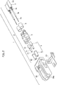
FIG. 2 shows an embodiment of the present invention and is an exploded perspective view of an optical connector; -
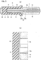
FIGS. 3(a) and 3(b) show the embodiment of the present invention, whereFIG. 3(a) is a sectional view of a ferrule andFIG. 3(b) is an enlarged view of a part A inFIG. 3(a) ; -
FIG. 4 shows the embodiment of the present invention and is a sectional view showing an assembling process of the ferrule; and -
FIG. 5 shows the embodiment of the present invention and is a sectional view showing an assembling process of the ferrule. - An embodiment of the present invention is explained below with reference to the accompanying drawings.
-
FIGS. 2 to 5 show an embodiment of the present invention. As shown inFIG. 2 , an optical connector 1 includes a pair offerrule assemblies 2, and a connector housing 20 that houses the pair offerrule assemblies 2. - The
respective ferrule assemblies 2 include anoptical fiber 3, aferrule 4 into which a forefront portion of an opticalfiber core wire 3a of theoptical fiber 3 is inserted, and acaulking sleeve 5 and acaulking ring 6 for fixing anexternal coating portion 3d and a tensile-strength fiber wire 3c of theoptical fiber 3 to theferrule 4. - The
optical fiber 3 is of a hollow type, and includes the opticalfiber core wire 3a, aninternal coating portion 3b that coats an outer circumference of the opticalfiber core wire 3a, a plurality of tensile-strength fiber wires 3c arranged along an outer circumference of theinternal coating portion 3b, and theexternal coating portion 3d that coats the tensile-strength fiber wires 3c. The opticalfiber core wire 3a is made of plastic (POF) and includes a core and a clad. - At the forefront side of the
optical fiber 3, theexternal coating portion 3d and theinternal coating portion 3b are stripped off, with a stripping size of theinternal coating portion 3b being shorter than that of theexternal coating portion 3d. Accordingly, the forefront side of theoptical fiber 3 is exposed in order of the opticalfiber core wire 3a, theinternal coating portion 3b, and the tensile-strength fiber wire 3c from the forefront toward the other end. - As shown in
FIGS. 2 and3(a) , the respective ferrules include aninner ferrule 7 that is an optical-fiber core-wire holding member having a fiber core-wire insertion hole 73, and alens ferrule 8 that is a lens member having alens unit 82 on an optical axis of the opticalfiber core wire 3a, into which a small-diametercylindrical portion 71 of theinner ferrule 7 is inserted. - The
inner ferrule 7 includes the small-diametercylindrical portion 71 having a small diameter and a large-diametercylindrical portion 72 having a large diameter integrally formed with the small-diametercylindrical portion 71. The fiber core-wire insertion hole 73 is formed at the center of the small-diametercylindrical portion 71 and the large-diametercylindrical portion 72. The fiber core-wire insertion hole 73 is formed of a small-diameter hole 73a formed approximately in the small-diametercylindrical portion 71 and a large-diameter hole 73b formed approximately in the large-diametercylindrical portion 72. The forefront of the fiber core-wire insertion hole 73 opens in a front end face of the small-diametercylindrical portion 71. A rear end of the fiber core-wire insertion hole 73 opens in a rear end face of the large-diametercylindrical portion 72. The forefront portion of theoptical fiber 3 is inserted into the fiber core-wire insertion hole 73. Specifically, the exposed opticalfiber core wire 3a is inserted into the small-diameter hole 73a, and the opticalfiber core wire 3a coated with theinternal coating portion 3b is inserted into the large-diameter hole 73b. An adhesive 10 is filled between an inner periphery of the small-diameter hole 73a of the fiber core-wire insertion hole 73 and an outer periphery of the opticalfiber core wire 3a. An inner periphery of the large-diameter hole 73b of the fiber core-wire insertion hole 73 and an outer periphery of theinternal coating portion 3b that coats the opticalfiber core wire 3a are fixed by alaser welding portion 11. - The
lens ferrule 8 is a cylindrical member, and is formed with an inner-ferrule insertion hole 81 at a center of the cylindrical member. A bottom face of the inner-ferrule insertion hole 81 is an end face facing the end face of the opticalfiber core wire 3a and located on the optical axis of the opticalfiber core wire 3a. Thelens unit 82 is formed on an external surface opposite to the end face. As shown inFIGS. 3(a) and 3(b) , the adhesive 10 is filled between the front end face of the small-diametercylindrical portion 71 of theinner ferrule 7 and the front end face of the opticalfiber core wire 3a and the end face of thelens ferrule 8, and between the outer periphery of the small-diametercylindrical portion 71 of theinner ferrule 7 and an inner surface of the inner-ferrule insertion hole 81 of thelens ferrule 8. As shown inFIG. 3(b) , theadhesive 10 is also filled in a gap between the inner periphery of the fiber core-wire insertion hole 73 and the outer periphery of the opticalfiber core wire 3 a. - The adhesive 10 is of an ultraviolet curing type. The adhesive 10 has a refractive index N, which is between a refractive index N1 of the
lens ferrule 8 and a refractive index N2 of the opticalfiber core wire 3a (N1<N<N2) in a cured state (a hardened state), and has an optical transparency. Preferably, it is desired that the adhesive 10 has a refractive index N of N=√(N1+N2) (N2=(N1+N2)), and has an optical transmittance of 90% or higher. - The
connector housing 20 has a pair offerrule housings 20a arranged in parallel with a gap therebetween. The pair offerrule assemblies 2 is housed in the pair offerrule housings 20a. Forward ends of therespective ferrule housings 20a open outward. At the time of being fitted to the other side optical connector (not shown), optical information is transferred via the openings of therespective ferrule housings 20a. - A
holder 21 is mounted on theconnector housing 20. The pair offerrule assemblies 2 is positioned by theholder 21 so as not to come off. - An assembling procedure of the
ferrule assembly 2 is explained next. Theuncured adhesive 10 of an ultraviolet curing type is first applied to at least one of the inner circumference of the fiber core-wire insertion hole 73 of theinner ferrule 7 and the outer circumference of the exposed opticalfiber core wire 3a. The opticalfiber core wire 3a of theoptical fiber 3 is inserted into the fiber core-wire insertion hole 73 of theinner ferrule 7. In this state, the forefront of the opticalfiber core wire 3a protrudes beyond at least the forefront of the fiber core-wire insertion hole 73. - Next, as shown in
FIG. 4 , laser beams are irradiated to a region of theinternal coating portion 3b of theoptical fiber 3 housed in theinner ferrule 7 to perform laser welding. Alternatively, theoptical fiber 3 can be bonded and fixed by the adhesive 10. - Next, as shown in
FIG. 4 , end face processing by cutting using acutting blade 30 and grinding using a grinder (not shown) is performed with respect to the front end face of theinner ferrule 7, from which the opticalfiber core wire 3a protrudes. Accordingly, the front end face of the opticalfiber core wire 3a and the front end face of theinner ferrule 7 become a flat surface flush with each other and having unevenness as little as possible. - The uncured adhesive of an ultraviolet curing type is then applied to at least one of the outer periphery of the small-diameter
cylindrical portion 71 of theinner ferrule 7 and the inner periphery of the inner-ferrule insertion hole 81 of thelens ferrule 8. - Optical beams are then emitted from the
optical fiber 3 to change a relative position (inclination and the like) of theinner ferrule 7 and thelens ferrule 8 while measuring a state of the optical beams irradiated via thelens unit 82, thereby determining an appropriate assembly position at which an output of the optical beams becomes largest. That is, the position adjustment is performed by active alignment. - Next, as shown in
FIG. 5 , ultraviolet rays are irradiated to theinner ferrule 7 and thelens ferrule 8 with positions thereof adjusted appropriately, by using anultraviolet light source 12 to cure the adhesive 10 of an ultraviolet curing type. - Next, the
external coating portion 3d and the tensile-strength fiber wire 3c of theoptical fiber 3 are fixed to theferrule 4 by thecaulking sleeve 5 and thecaulking ring 6. The procedure is then completed. - As described above, the adhesive 10 having the refractive index N, which is between the refractive index N1 of the
lens ferrule 8 and the refractive index N2 of the opticalfiber core wire 3a (N1<N<N2), and having the optical transparency is filled between the front end face of the opticalfiber core wire 3a and the end face of thelens ferrule 8 opposite thereto. Accordingly, a scattering loss due to surface roughness of the respective end faces of the opticalfiber core wire 3a and thelens ferrule 8 can be reduced, and a Fresnel loss (Fresnel reflection loss) can be reduced as compared with a case in which air is present between the end face of the opticalfiber core wire 3a and the end face of thelens ferrule 8. That is, because the adhesive 10 that fixes between theinner ferrule 7 and thelens ferrule 8 works as a substitute of the optical coupling-loss reducing unit, the optical coupling-loss reducing unit need not be installed separately as in the conventional example. Further, the adhesive 10 is cheaper than the refractive-index matching plate. Accordingly, the optical coupling loss between the end face of the opticalfiber core wire 3a and thelens ferrule 8 can be reduced, the installation work can be simplified, and cost reduction can be achieved. - When the adhesive 10 having the refractive index N of N=√(N1+N2) and an optical transmittance of 90% or higher is used, the Fresnel loss described above can be sufficiently reduced, and almost all optical beams penetrate therethrough. Accordingly, the optical coupling loss can be reduced reliably and sufficiently. However, for example, when the refractive index N2 of the optical
fiber core wire 3a is 1.52, and the refractive index N1 of thelens ferrule 8 is 1.48, the refractive index N of the adhesive 10 could also be set to 1.5. - The adhesive 10 is also filled in the gap between the inner periphery of the fiber core-
wire insertion hole 73 and the outer periphery of the opticalfiber core wire 3a. Accordingly, misalignment due to the gap between the inner periphery of the fiber core-wire insertion hole 73 and the outer periphery of the opticalfiber core wire 3a, for example, misalignment due to vibration can be prevented. Accordingly, a loss of optical communication due to misalignment of the opticalfiber core wire 3a with respect to theinner ferrule 7 can be suppressed. - While the optical
fiber core wire 3a is made of plastic in the above embodiment, the opticalfiber core wire 3a can be made of glass. For example, when thelens ferrule 8 is made of a cyclic olefin copolymer (COC), and the opticalfiber core wire 3a is made of glass, the refractive index N1 of thelens ferrule 8 is 1.53, and the refractive index N2 of the opticalfiber core wire 3a is 1.48. In this case, it is preferable that the refractive index N of the cured adhesive 10 is 1.50. - The adhesive 10 is of an ultraviolet curing type. However, the adhesive 10 can be any adhesive that can be cured by adding energy to the adhesive in a molten state. For example, the adhesive 10 can be of a thermosetting type.
- The Japanese Patent Application
P2013-146193 (filed on July 12, 2013 - Although the invention has been described above by reference to certain embodiments of the invention, the invention is not limited to the embodiments described above. Modifications and variations of the embodiments described above will occur to those skilled in the art, in light of the above teachings. The scope of the invention is defined by the following claims.
Claims (3)
- An optical connector (1), comprising:an optical-fiber core-wire holding member (7) having a fiber core-wire insertion hole (73), into which an optical fiber core wire (3a) of an optical fiber (3) is inserted, with a front end face of the optical fiber core wire (3a) inserted into the fiber core-wire insertion hole (73) so as to be exposed; anda lens member (8) having a lens unit (82) arranged on an axis of the optical fiber core wire (3a) and made of a light transmitting material,wherein an adhesive (10) having a refractive index N, which is between a refractive index N1 of the lens member (8) and a refractive index N2 of the optical fiber core wire (3a), and having optical transparency is filled between the front end face of the optical fiber core wire (3a) and an end face of the lens member (8) opposite to the front end face of the optical fiber core wire (3a),wherein the optical-fiber core-wire holding member (7) includes a cylindrical portion (71) having a small outer diameter and a cylindrical portion (72) having a large outer diameter, the large-diameter cylindrical portion (72) being integrally formed with the small-diameter cylindrical portion (71),the fiber core-wire insertion hole (73) is formed at the center of the small-diameter cylindrical portion (71) and the large-diameter cylindrical portion (72),the fiber core-wire insertion hole (73) is formed of a small-diameter hole (73a) formed in the small-diameter cylindrical portion (71) and a large-diameter hole (73b) formed in the large-diameter cylindrical portion (72),the exposed optical fiber core wire (3a) is inserted into the small-diameter hole (73a), wherein the adhesive (10) is also filled between an inner periphery of the small-diameter hole (73a) and an outer periphery of the exposed optical fiber core wire (3a),the optical fiber core wire (3a) coated with an internal coating portion (3b) is inserted into the large-diameter hole (73b), wherein an inner periphery of the large-diameter hole (73b) and an outer periphery of the internal coating portion (3b) are fixed by a laser welding portion (11), andthe adhesive (10) is also filled between an outer periphery of the small-diameter cylindrical portion (71) of the optical-fiber core-wire holding member (7) and an inner surface of an inner-ferrule insertion hole (81) of the lens member (8).
- The optical connector according to claim 1, wherein the adhesive (10) has a refractive index N of N=√(N1+N2) and has an optical transmittance of 90% or higher in a cured state.
- The optical connector according to claim 1, wherein
the optical-fiber core-wire holding member (7) is an inner ferrule having the fiber core-wire insertion hole (73)
Applications Claiming Priority (1)
| Application Number | Priority Date | Filing Date | Title |
|---|---|---|---|
| JP2013146193A JP2015018154A (en) | 2013-07-12 | 2013-07-12 | Optical connector |
Publications (2)
| Publication Number | Publication Date |
|---|---|
| EP2824491A1 EP2824491A1 (en) | 2015-01-14 |
| EP2824491B1 true EP2824491B1 (en) | 2020-01-22 |
Family
ID=51162549
Family Applications (1)
| Application Number | Title | Priority Date | Filing Date |
|---|---|---|---|
| EP14176304.5A Active EP2824491B1 (en) | 2013-07-12 | 2014-07-09 | Optical connector |
Country Status (2)
| Country | Link |
|---|---|
| EP (1) | EP2824491B1 (en) |
| JP (1) | JP2015018154A (en) |
Families Citing this family (1)
| Publication number | Priority date | Publication date | Assignee | Title |
|---|---|---|---|---|
| JP6652812B2 (en) * | 2015-10-29 | 2020-02-26 | 矢崎総業株式会社 | Ferrule |
Citations (2)
| Publication number | Priority date | Publication date | Assignee | Title |
|---|---|---|---|---|
| DE4221040A1 (en) * | 1992-06-26 | 1994-01-05 | Ant Nachrichtentech | Optical fibre connector plug mfr. - inserting optical fibre into cylindrical sleeve before inserting into cylindrical lens element providing collimated beam |
| JP2010096903A (en) * | 2008-10-15 | 2010-04-30 | Yazaki Corp | Optical fiber module and method of manufacturing the same |
Family Cites Families (9)
| Publication number | Priority date | Publication date | Assignee | Title |
|---|---|---|---|---|
| CA1144794A (en) * | 1980-01-17 | 1983-04-19 | W. John Carlsen | Optical fiber connectors |
| JPS5948517U (en) * | 1982-09-24 | 1984-03-31 | オムロン株式会社 | optical coupling device |
| US5097524A (en) * | 1990-05-17 | 1992-03-17 | G & H Technology, Inc. | Optical fiber termination |
| JPH0572444A (en) | 1991-09-17 | 1993-03-26 | Fujitsu Ltd | Multifiber optical connector |
| US5231684A (en) * | 1992-06-22 | 1993-07-27 | Pdt Systems | Optical fiber microlens |
| KR100294041B1 (en) * | 1997-02-24 | 2001-07-12 | 윤종용 | Optical part packaging method and collimatior assembly mounting method |
| US20130177280A1 (en) * | 2006-06-19 | 2013-07-11 | Commscope, Inc. Of North Carolina | Expanded Beam Connector Concepts |
| JP5673223B2 (en) * | 2011-03-04 | 2015-02-18 | ソニー株式会社 | OPTICAL FIBER COMPONENT AND ITS MANUFACTURING METHOD, OPTICAL FIBER / LENS SUBSTRATE ASSEMBLY AND ITS MANUFACTURING METHOD |
| US9405076B2 (en) * | 2011-07-29 | 2016-08-02 | Molex, Llc | Multi-fiber ferrule with a lens plate |
-
2013
- 2013-07-12 JP JP2013146193A patent/JP2015018154A/en not_active Abandoned
-
2014
- 2014-07-09 EP EP14176304.5A patent/EP2824491B1/en active Active
Patent Citations (2)
| Publication number | Priority date | Publication date | Assignee | Title |
|---|---|---|---|---|
| DE4221040A1 (en) * | 1992-06-26 | 1994-01-05 | Ant Nachrichtentech | Optical fibre connector plug mfr. - inserting optical fibre into cylindrical sleeve before inserting into cylindrical lens element providing collimated beam |
| JP2010096903A (en) * | 2008-10-15 | 2010-04-30 | Yazaki Corp | Optical fiber module and method of manufacturing the same |
Also Published As
| Publication number | Publication date |
|---|---|
| JP2015018154A (en) | 2015-01-29 |
| EP2824491A1 (en) | 2015-01-14 |
Similar Documents
| Publication | Publication Date | Title |
|---|---|---|
| JP6203179B2 (en) | Optical connector having a plurality of optical fibers with staggered cleaved ends coupled to associated microlenses | |
| EP2839326B1 (en) | Fiber optic modules having a fiber tray, optical-to-optical fiber optic connectors, and methods thereof | |
| EP3640692B1 (en) | Optical connector module | |
| US6600855B2 (en) | Reflection suppression in multiple-reflector collimation system | |
| US9588302B2 (en) | Expanded-beam connector with molded lens | |
| TWI416186B (en) | An optical collimator and a light connector for use, and a holding member for an optical collimator | |
| JP2014526719A5 (en) | ||
| US9022669B2 (en) | Gradient index lens assemblies, fiber optic connectors, and fiber optic cable assemblies employing lens alignment channels | |
| JP5369046B2 (en) | Optical fiber array, optical switch, optical fiber, and end face processing method | |
| US7503703B1 (en) | Ferrule for optical networks | |
| EP2713190B1 (en) | Optical fiber head | |
| KR101760156B1 (en) | Optical collimator and optical connector using same | |
| JP2016184106A (en) | Ferrule with optical fiber, optical connector system, and method for manufacturing the ferrule with optical fiber | |
| EP2824491B1 (en) | Optical connector | |
| JP2018136551A (en) | Optical Receptacle and Optical Transceiver | |
| JP5543293B2 (en) | Small-diameter bending optical connector | |
| KR101854956B1 (en) | Optically coupling member, optical connector using same, and member for holding optically coupling member | |
| US9690055B2 (en) | Laser-based systems and methods for fiber-to-ferrule bonding for optical fiber connectors | |
| JP5657944B2 (en) | Optical connector with lens | |
| JP2005316295A (en) | Optical fiber module | |
| JP2005321425A (en) | Ferrule opposition structure | |
| JP2017062342A (en) | Optical module and manufacturing method thereof | |
| JP6652812B2 (en) | Ferrule | |
| WO2018003940A1 (en) | Optical receptacle and optical transceiver | |
| JP2020129063A (en) | Optical fiber, multiple optical fiber, and optical connector |
Legal Events
| Date | Code | Title | Description |
|---|---|---|---|
| 17P | Request for examination filed |
Effective date: 20140709 |
|
| AK | Designated contracting states |
Kind code of ref document: A1 Designated state(s): AL AT BE BG CH CY CZ DE DK EE ES FI FR GB GR HR HU IE IS IT LI LT LU LV MC MK MT NL NO PL PT RO RS SE SI SK SM TR |
|
| AX | Request for extension of the european patent |
Extension state: BA ME |
|
| PUAI | Public reference made under article 153(3) epc to a published international application that has entered the european phase |
Free format text: ORIGINAL CODE: 0009012 |
|
| STAA | Information on the status of an ep patent application or granted ep patent |
Free format text: STATUS: EXAMINATION IS IN PROGRESS |
|
| 17Q | First examination report despatched |
Effective date: 20180418 |
|
| GRAP | Despatch of communication of intention to grant a patent |
Free format text: ORIGINAL CODE: EPIDOSNIGR1 |
|
| STAA | Information on the status of an ep patent application or granted ep patent |
Free format text: STATUS: GRANT OF PATENT IS INTENDED |
|
| INTG | Intention to grant announced |
Effective date: 20190926 |
|
| GRAS | Grant fee paid |
Free format text: ORIGINAL CODE: EPIDOSNIGR3 |
|
| GRAA | (expected) grant |
Free format text: ORIGINAL CODE: 0009210 |
|
| STAA | Information on the status of an ep patent application or granted ep patent |
Free format text: STATUS: THE PATENT HAS BEEN GRANTED |
|
| AK | Designated contracting states |
Kind code of ref document: B1 Designated state(s): AL AT BE BG CH CY CZ DE DK EE ES FI FR GB GR HR HU IE IS IT LI LT LU LV MC MK MT NL NO PL PT RO RS SE SI SK SM TR |
|
| REG | Reference to a national code |
Ref country code: GB Ref legal event code: FG4D |
|
| REG | Reference to a national code |
Ref country code: CH Ref legal event code: EP |
|
| REG | Reference to a national code |
Ref country code: AT Ref legal event code: REF Ref document number: 1227269 Country of ref document: AT Kind code of ref document: T Effective date: 20200215 |
|
| REG | Reference to a national code |
Ref country code: IE Ref legal event code: FG4D |
|
| REG | Reference to a national code |
Ref country code: DE Ref legal event code: R096 Ref document number: 602014060261 Country of ref document: DE |
|
| REG | Reference to a national code |
Ref country code: SE Ref legal event code: TRGR |
|
| REG | Reference to a national code |
Ref country code: NL Ref legal event code: MP Effective date: 20200122 |
|
| REG | Reference to a national code |
Ref country code: LT Ref legal event code: MG4D |
|
| PG25 | Lapsed in a contracting state [announced via postgrant information from national office to epo] |
Ref country code: NL Free format text: LAPSE BECAUSE OF FAILURE TO SUBMIT A TRANSLATION OF THE DESCRIPTION OR TO PAY THE FEE WITHIN THE PRESCRIBED TIME-LIMIT Effective date: 20200122 Ref country code: RS Free format text: LAPSE BECAUSE OF FAILURE TO SUBMIT A TRANSLATION OF THE DESCRIPTION OR TO PAY THE FEE WITHIN THE PRESCRIBED TIME-LIMIT Effective date: 20200122 Ref country code: PT Free format text: LAPSE BECAUSE OF FAILURE TO SUBMIT A TRANSLATION OF THE DESCRIPTION OR TO PAY THE FEE WITHIN THE PRESCRIBED TIME-LIMIT Effective date: 20200614 Ref country code: FI Free format text: LAPSE BECAUSE OF FAILURE TO SUBMIT A TRANSLATION OF THE DESCRIPTION OR TO PAY THE FEE WITHIN THE PRESCRIBED TIME-LIMIT Effective date: 20200122 Ref country code: NO Free format text: LAPSE BECAUSE OF FAILURE TO SUBMIT A TRANSLATION OF THE DESCRIPTION OR TO PAY THE FEE WITHIN THE PRESCRIBED TIME-LIMIT Effective date: 20200422 |
|
| PG25 | Lapsed in a contracting state [announced via postgrant information from national office to epo] |
Ref country code: BG Free format text: LAPSE BECAUSE OF FAILURE TO SUBMIT A TRANSLATION OF THE DESCRIPTION OR TO PAY THE FEE WITHIN THE PRESCRIBED TIME-LIMIT Effective date: 20200422 Ref country code: GR Free format text: LAPSE BECAUSE OF FAILURE TO SUBMIT A TRANSLATION OF THE DESCRIPTION OR TO PAY THE FEE WITHIN THE PRESCRIBED TIME-LIMIT Effective date: 20200423 Ref country code: HR Free format text: LAPSE BECAUSE OF FAILURE TO SUBMIT A TRANSLATION OF THE DESCRIPTION OR TO PAY THE FEE WITHIN THE PRESCRIBED TIME-LIMIT Effective date: 20200122 Ref country code: LV Free format text: LAPSE BECAUSE OF FAILURE TO SUBMIT A TRANSLATION OF THE DESCRIPTION OR TO PAY THE FEE WITHIN THE PRESCRIBED TIME-LIMIT Effective date: 20200122 Ref country code: IS Free format text: LAPSE BECAUSE OF FAILURE TO SUBMIT A TRANSLATION OF THE DESCRIPTION OR TO PAY THE FEE WITHIN THE PRESCRIBED TIME-LIMIT Effective date: 20200522 |
|
| REG | Reference to a national code |
Ref country code: DE Ref legal event code: R097 Ref document number: 602014060261 Country of ref document: DE |
|
| PG25 | Lapsed in a contracting state [announced via postgrant information from national office to epo] |
Ref country code: SK Free format text: LAPSE BECAUSE OF FAILURE TO SUBMIT A TRANSLATION OF THE DESCRIPTION OR TO PAY THE FEE WITHIN THE PRESCRIBED TIME-LIMIT Effective date: 20200122 Ref country code: RO Free format text: LAPSE BECAUSE OF FAILURE TO SUBMIT A TRANSLATION OF THE DESCRIPTION OR TO PAY THE FEE WITHIN THE PRESCRIBED TIME-LIMIT Effective date: 20200122 Ref country code: DK Free format text: LAPSE BECAUSE OF FAILURE TO SUBMIT A TRANSLATION OF THE DESCRIPTION OR TO PAY THE FEE WITHIN THE PRESCRIBED TIME-LIMIT Effective date: 20200122 Ref country code: SM Free format text: LAPSE BECAUSE OF FAILURE TO SUBMIT A TRANSLATION OF THE DESCRIPTION OR TO PAY THE FEE WITHIN THE PRESCRIBED TIME-LIMIT Effective date: 20200122 Ref country code: EE Free format text: LAPSE BECAUSE OF FAILURE TO SUBMIT A TRANSLATION OF THE DESCRIPTION OR TO PAY THE FEE WITHIN THE PRESCRIBED TIME-LIMIT Effective date: 20200122 Ref country code: ES Free format text: LAPSE BECAUSE OF FAILURE TO SUBMIT A TRANSLATION OF THE DESCRIPTION OR TO PAY THE FEE WITHIN THE PRESCRIBED TIME-LIMIT Effective date: 20200122 Ref country code: CZ Free format text: LAPSE BECAUSE OF FAILURE TO SUBMIT A TRANSLATION OF THE DESCRIPTION OR TO PAY THE FEE WITHIN THE PRESCRIBED TIME-LIMIT Effective date: 20200122 Ref country code: LT Free format text: LAPSE BECAUSE OF FAILURE TO SUBMIT A TRANSLATION OF THE DESCRIPTION OR TO PAY THE FEE WITHIN THE PRESCRIBED TIME-LIMIT Effective date: 20200122 |
|
| REG | Reference to a national code |
Ref country code: AT Ref legal event code: MK05 Ref document number: 1227269 Country of ref document: AT Kind code of ref document: T Effective date: 20200122 |
|
| PLBE | No opposition filed within time limit |
Free format text: ORIGINAL CODE: 0009261 |
|
| STAA | Information on the status of an ep patent application or granted ep patent |
Free format text: STATUS: NO OPPOSITION FILED WITHIN TIME LIMIT |
|
| 26N | No opposition filed |
Effective date: 20201023 |
|
| PG25 | Lapsed in a contracting state [announced via postgrant information from national office to epo] |
Ref country code: IT Free format text: LAPSE BECAUSE OF FAILURE TO SUBMIT A TRANSLATION OF THE DESCRIPTION OR TO PAY THE FEE WITHIN THE PRESCRIBED TIME-LIMIT Effective date: 20200122 Ref country code: AT Free format text: LAPSE BECAUSE OF FAILURE TO SUBMIT A TRANSLATION OF THE DESCRIPTION OR TO PAY THE FEE WITHIN THE PRESCRIBED TIME-LIMIT Effective date: 20200122 |
|
| PG25 | Lapsed in a contracting state [announced via postgrant information from national office to epo] |
Ref country code: SI Free format text: LAPSE BECAUSE OF FAILURE TO SUBMIT A TRANSLATION OF THE DESCRIPTION OR TO PAY THE FEE WITHIN THE PRESCRIBED TIME-LIMIT Effective date: 20200122 Ref country code: MC Free format text: LAPSE BECAUSE OF FAILURE TO SUBMIT A TRANSLATION OF THE DESCRIPTION OR TO PAY THE FEE WITHIN THE PRESCRIBED TIME-LIMIT Effective date: 20200122 Ref country code: PL Free format text: LAPSE BECAUSE OF FAILURE TO SUBMIT A TRANSLATION OF THE DESCRIPTION OR TO PAY THE FEE WITHIN THE PRESCRIBED TIME-LIMIT Effective date: 20200122 |
|
| REG | Reference to a national code |
Ref country code: CH Ref legal event code: PL |
|
| GBPC | Gb: european patent ceased through non-payment of renewal fee |
Effective date: 20200709 |
|
| REG | Reference to a national code |
Ref country code: BE Ref legal event code: MM Effective date: 20200731 |
|
| PG25 | Lapsed in a contracting state [announced via postgrant information from national office to epo] |
Ref country code: FR Free format text: LAPSE BECAUSE OF NON-PAYMENT OF DUE FEES Effective date: 20200731 Ref country code: LU Free format text: LAPSE BECAUSE OF NON-PAYMENT OF DUE FEES Effective date: 20200709 Ref country code: GB Free format text: LAPSE BECAUSE OF NON-PAYMENT OF DUE FEES Effective date: 20200709 Ref country code: LI Free format text: LAPSE BECAUSE OF NON-PAYMENT OF DUE FEES Effective date: 20200731 Ref country code: CH Free format text: LAPSE BECAUSE OF NON-PAYMENT OF DUE FEES Effective date: 20200731 |
|
| PG25 | Lapsed in a contracting state [announced via postgrant information from national office to epo] |
Ref country code: BE Free format text: LAPSE BECAUSE OF NON-PAYMENT OF DUE FEES Effective date: 20200731 |
|
| PG25 | Lapsed in a contracting state [announced via postgrant information from national office to epo] |
Ref country code: IE Free format text: LAPSE BECAUSE OF NON-PAYMENT OF DUE FEES Effective date: 20200709 |
|
| PG25 | Lapsed in a contracting state [announced via postgrant information from national office to epo] |
Ref country code: TR Free format text: LAPSE BECAUSE OF FAILURE TO SUBMIT A TRANSLATION OF THE DESCRIPTION OR TO PAY THE FEE WITHIN THE PRESCRIBED TIME-LIMIT Effective date: 20200122 Ref country code: MT Free format text: LAPSE BECAUSE OF FAILURE TO SUBMIT A TRANSLATION OF THE DESCRIPTION OR TO PAY THE FEE WITHIN THE PRESCRIBED TIME-LIMIT Effective date: 20200122 Ref country code: CY Free format text: LAPSE BECAUSE OF FAILURE TO SUBMIT A TRANSLATION OF THE DESCRIPTION OR TO PAY THE FEE WITHIN THE PRESCRIBED TIME-LIMIT Effective date: 20200122 |
|
| PG25 | Lapsed in a contracting state [announced via postgrant information from national office to epo] |
Ref country code: MK Free format text: LAPSE BECAUSE OF FAILURE TO SUBMIT A TRANSLATION OF THE DESCRIPTION OR TO PAY THE FEE WITHIN THE PRESCRIBED TIME-LIMIT Effective date: 20200122 Ref country code: AL Free format text: LAPSE BECAUSE OF FAILURE TO SUBMIT A TRANSLATION OF THE DESCRIPTION OR TO PAY THE FEE WITHIN THE PRESCRIBED TIME-LIMIT Effective date: 20200122 |
|
| PGFP | Annual fee paid to national office [announced via postgrant information from national office to epo] |
Ref country code: SE Payment date: 20220615 Year of fee payment: 9 |
|
| PGFP | Annual fee paid to national office [announced via postgrant information from national office to epo] |
Ref country code: DE Payment date: 20220531 Year of fee payment: 9 |
|
| REG | Reference to a national code |
Ref country code: DE Ref legal event code: R119 Ref document number: 602014060261 Country of ref document: DE |
|
| REG | Reference to a national code |
Ref country code: SE Ref legal event code: EUG |
|
| PG25 | Lapsed in a contracting state [announced via postgrant information from national office to epo] |
Ref country code: DE Free format text: LAPSE BECAUSE OF NON-PAYMENT OF DUE FEES Effective date: 20240201 |