EP2824411A2 - Heat exchange device - Google Patents
Heat exchange device Download PDFInfo
- Publication number
- EP2824411A2 EP2824411A2 EP14175589.2A EP14175589A EP2824411A2 EP 2824411 A2 EP2824411 A2 EP 2824411A2 EP 14175589 A EP14175589 A EP 14175589A EP 2824411 A2 EP2824411 A2 EP 2824411A2
- Authority
- EP
- European Patent Office
- Prior art keywords
- tubes
- heat exchanger
- radiator
- exchange device
- heat exchange
- Prior art date
- Legal status (The legal status is an assumption and is not a legal conclusion. Google has not performed a legal analysis and makes no representation as to the accuracy of the status listed.)
- Withdrawn
Links
- 239000012530 fluid Substances 0.000 claims abstract description 8
- 239000002184 metal Substances 0.000 claims description 10
- 238000005452 bending Methods 0.000 claims description 2
- 238000005219 brazing Methods 0.000 description 8
- 238000001816 cooling Methods 0.000 description 3
- 230000000052 comparative effect Effects 0.000 description 2
- 239000002826 coolant Substances 0.000 description 2
- 239000000498 cooling water Substances 0.000 description 2
- 239000000463 material Substances 0.000 description 2
- 238000000034 method Methods 0.000 description 2
- 239000011347 resin Substances 0.000 description 2
- 229920005989 resin Polymers 0.000 description 2
- 230000003247 decreasing effect Effects 0.000 description 1
- 230000000694 effects Effects 0.000 description 1
- 230000002349 favourable effect Effects 0.000 description 1
- 238000010438 heat treatment Methods 0.000 description 1
Images






Classifications
-
- F—MECHANICAL ENGINEERING; LIGHTING; HEATING; WEAPONS; BLASTING
- F25—REFRIGERATION OR COOLING; COMBINED HEATING AND REFRIGERATION SYSTEMS; HEAT PUMP SYSTEMS; MANUFACTURE OR STORAGE OF ICE; LIQUEFACTION SOLIDIFICATION OF GASES
- F25B—REFRIGERATION MACHINES, PLANTS OR SYSTEMS; COMBINED HEATING AND REFRIGERATION SYSTEMS; HEAT PUMP SYSTEMS
- F25B39/00—Evaporators; Condensers
- F25B39/04—Condensers
-
- F—MECHANICAL ENGINEERING; LIGHTING; HEATING; WEAPONS; BLASTING
- F28—HEAT EXCHANGE IN GENERAL
- F28D—HEAT-EXCHANGE APPARATUS, NOT PROVIDED FOR IN ANOTHER SUBCLASS, IN WHICH THE HEAT-EXCHANGE MEDIA DO NOT COME INTO DIRECT CONTACT
- F28D1/00—Heat-exchange apparatus having stationary conduit assemblies for one heat-exchange medium only, the media being in contact with different sides of the conduit wall, in which the other heat-exchange medium is a large body of fluid, e.g. domestic or motor car radiators
- F28D1/02—Heat-exchange apparatus having stationary conduit assemblies for one heat-exchange medium only, the media being in contact with different sides of the conduit wall, in which the other heat-exchange medium is a large body of fluid, e.g. domestic or motor car radiators with heat-exchange conduits immersed in the body of fluid
- F28D1/04—Heat-exchange apparatus having stationary conduit assemblies for one heat-exchange medium only, the media being in contact with different sides of the conduit wall, in which the other heat-exchange medium is a large body of fluid, e.g. domestic or motor car radiators with heat-exchange conduits immersed in the body of fluid with tubular conduits
- F28D1/0408—Multi-circuit heat exchangers, e.g. integrating different heat exchange sections in the same unit or heat exchangers for more than two fluids
- F28D1/0426—Multi-circuit heat exchangers, e.g. integrating different heat exchange sections in the same unit or heat exchangers for more than two fluids with units having particular arrangement relative to the large body of fluid, e.g. with interleaved units or with adjacent heat exchange units in common air flow or with units extending at an angle to each other or with units arranged around a central element
- F28D1/0435—Combination of units extending one behind the other
-
- F—MECHANICAL ENGINEERING; LIGHTING; HEATING; WEAPONS; BLASTING
- F28—HEAT EXCHANGE IN GENERAL
- F28D—HEAT-EXCHANGE APPARATUS, NOT PROVIDED FOR IN ANOTHER SUBCLASS, IN WHICH THE HEAT-EXCHANGE MEDIA DO NOT COME INTO DIRECT CONTACT
- F28D1/00—Heat-exchange apparatus having stationary conduit assemblies for one heat-exchange medium only, the media being in contact with different sides of the conduit wall, in which the other heat-exchange medium is a large body of fluid, e.g. domestic or motor car radiators
- F28D1/02—Heat-exchange apparatus having stationary conduit assemblies for one heat-exchange medium only, the media being in contact with different sides of the conduit wall, in which the other heat-exchange medium is a large body of fluid, e.g. domestic or motor car radiators with heat-exchange conduits immersed in the body of fluid
- F28D1/04—Heat-exchange apparatus having stationary conduit assemblies for one heat-exchange medium only, the media being in contact with different sides of the conduit wall, in which the other heat-exchange medium is a large body of fluid, e.g. domestic or motor car radiators with heat-exchange conduits immersed in the body of fluid with tubular conduits
- F28D1/053—Heat-exchange apparatus having stationary conduit assemblies for one heat-exchange medium only, the media being in contact with different sides of the conduit wall, in which the other heat-exchange medium is a large body of fluid, e.g. domestic or motor car radiators with heat-exchange conduits immersed in the body of fluid with tubular conduits the conduits being straight
- F28D1/0535—Heat-exchange apparatus having stationary conduit assemblies for one heat-exchange medium only, the media being in contact with different sides of the conduit wall, in which the other heat-exchange medium is a large body of fluid, e.g. domestic or motor car radiators with heat-exchange conduits immersed in the body of fluid with tubular conduits the conduits being straight the conduits having a non-circular cross-section
- F28D1/05366—Assemblies of conduits connected to common headers, e.g. core type radiators
-
- F—MECHANICAL ENGINEERING; LIGHTING; HEATING; WEAPONS; BLASTING
- F28—HEAT EXCHANGE IN GENERAL
- F28F—DETAILS OF HEAT-EXCHANGE AND HEAT-TRANSFER APPARATUS, OF GENERAL APPLICATION
- F28F9/00—Casings; Header boxes; Auxiliary supports for elements; Auxiliary members within casings
- F28F9/001—Casings in the form of plate-like arrangements; Frames enclosing a heat exchange core
-
- F—MECHANICAL ENGINEERING; LIGHTING; HEATING; WEAPONS; BLASTING
- F28—HEAT EXCHANGE IN GENERAL
- F28F—DETAILS OF HEAT-EXCHANGE AND HEAT-TRANSFER APPARATUS, OF GENERAL APPLICATION
- F28F9/00—Casings; Header boxes; Auxiliary supports for elements; Auxiliary members within casings
- F28F9/02—Header boxes; End plates
-
- F—MECHANICAL ENGINEERING; LIGHTING; HEATING; WEAPONS; BLASTING
- F25—REFRIGERATION OR COOLING; COMBINED HEATING AND REFRIGERATION SYSTEMS; HEAT PUMP SYSTEMS; MANUFACTURE OR STORAGE OF ICE; LIQUEFACTION SOLIDIFICATION OF GASES
- F25B—REFRIGERATION MACHINES, PLANTS OR SYSTEMS; COMBINED HEATING AND REFRIGERATION SYSTEMS; HEAT PUMP SYSTEMS
- F25B2339/00—Details of evaporators; Details of condensers
- F25B2339/04—Details of condensers
-
- F—MECHANICAL ENGINEERING; LIGHTING; HEATING; WEAPONS; BLASTING
- F28—HEAT EXCHANGE IN GENERAL
- F28D—HEAT-EXCHANGE APPARATUS, NOT PROVIDED FOR IN ANOTHER SUBCLASS, IN WHICH THE HEAT-EXCHANGE MEDIA DO NOT COME INTO DIRECT CONTACT
- F28D21/00—Heat-exchange apparatus not covered by any of the groups F28D1/00 - F28D20/00
- F28D2021/0019—Other heat exchangers for particular applications; Heat exchange systems not otherwise provided for
- F28D2021/008—Other heat exchangers for particular applications; Heat exchange systems not otherwise provided for for vehicles
- F28D2021/0084—Condensers
-
- F—MECHANICAL ENGINEERING; LIGHTING; HEATING; WEAPONS; BLASTING
- F28—HEAT EXCHANGE IN GENERAL
- F28D—HEAT-EXCHANGE APPARATUS, NOT PROVIDED FOR IN ANOTHER SUBCLASS, IN WHICH THE HEAT-EXCHANGE MEDIA DO NOT COME INTO DIRECT CONTACT
- F28D21/00—Heat-exchange apparatus not covered by any of the groups F28D1/00 - F28D20/00
- F28D2021/0019—Other heat exchangers for particular applications; Heat exchange systems not otherwise provided for
- F28D2021/008—Other heat exchangers for particular applications; Heat exchange systems not otherwise provided for for vehicles
- F28D2021/0091—Radiators
- F28D2021/0094—Radiators for recooling the engine coolant
-
- F—MECHANICAL ENGINEERING; LIGHTING; HEATING; WEAPONS; BLASTING
- F28—HEAT EXCHANGE IN GENERAL
- F28F—DETAILS OF HEAT-EXCHANGE AND HEAT-TRANSFER APPARATUS, OF GENERAL APPLICATION
- F28F9/00—Casings; Header boxes; Auxiliary supports for elements; Auxiliary members within casings
- F28F9/02—Header boxes; End plates
- F28F2009/0285—Other particular headers or end plates
Definitions
- the present invention relates to a heat exchange device.
- JP11-223486A discloses a device in which a tank of a radiator and a side plate of a condenser are brazed and bonded to each other.
- the radiator and the condenser are bonded to each other and then attached to the vehicle body or the like.
- the number of parts can be reduced, so that the above problem can be solved.
- the present invention is achieved in consideration with such a point, and an object thereof is to stably attach a condenser and a radiator while reducing the number of parts to reduce weight, suppress cost, and decrease the processing man-hour.
- a heat exchange device is a heat exchange device in which a first heat exchanger and a second heat exchanger are arranged in parallel along the air flow direction, wherein a side plate of the first heat exchanger is integrated with a tank communicating with tubes of the second heat exchanger through which a fluid flows.
- the first heat exchanger and the second heat exchanger can be stably attached while reducing the number of parts to reduce weight, suppress cost, and decrease the processing man-hour.
- a heat exchange device 1 of a first embodiment of the present invention will be described with reference to the drawings.
- Fig. 1 is a perspective view of the heat exchange device 1 for a vehicle.
- Fig. 2 is an enlarged perspective view of the upper end side of the heat exchange device 1.
- the heat exchange device 1 includes a radiator 2 and a condenser 3.
- the radiator 2 and the condenser 3 are arranged in parallel along the flow direction of running wind.
- the heat exchange device 1 to be mounted in the vehicle will be described herein.
- the present invention is not limited to this but only requires a plurality of heat exchangers such as the radiator 2 and the condenser 3 to be arranged in parallel along the air flow direction.
- the radiator 2 includes radiator tanks 20, a first core portion 21, and first side plates 22.
- Each of the radiator tanks 20 includes a metal plate 23, a resin tank body 24, and attachment portions 25 for attaching the radiator 2 and the condenser 3 to a vehicle body.
- the tank body 24 and the plate 23 are integrated by swaging and fixing a part of the plate 23 to the tank body 24.
- the first core portion 21 includes first tubes 26 and first fins 27.
- the first tubes 26 extend along the vertical direction and have ends communicating with the plates 23 of the radiator tanks 20.
- the plurality of first tube 26 is arranged along the horizontal direction, and each of the first fins 27 is provided between the adjacent first tubes 26.
- the first cooling water (fluid) whose temperature is increased by cooling for example an engine or the like flows through the first tubes 26, and the first cooling water is cooled by performing heat exchange with the air flowing outside the first tubes 26.
- the first side plates 22 extend along the longitudinal direction of the first tubes 26, that is, along the vertical direction, and are arranged on the both end sides of the first core portion 21.
- the first side plates 22 are bonded to the radiator tanks 20 to reinforce the first core portion 21.
- the first side plates 22 are made of metal and integrated with header tanks 30 to be described later.
- the condenser 3 includes the header tanks 30, a second core portion 31, and second side plates 32.
- the header tanks 30 are made of metal and integrated with the first side plates 22 of the radiator 2.
- the second core portion 31 includes second tubes 33 and second fins 34.
- the second tubes 33 extend along the horizontal direction and have ends communicating with the header tanks 30.
- the plurality of second tubes 33 is arranged along the vertical direction, and each of the second fins 34 is provided between the adjacent second tubes 33.
- a cooling medium (fluid) pressurized by a compressor or the like flows through the second tubes 33, and the cooling medium is cooled and liquefied by performing heat exchange with the air flowing outside.
- the longitudinal direction of the first tubes 26 and the longitudinal direction of the second tubes 33 are different by 90 degrees, and points where the first tubes 26 and the second tubes 33 are in contact with each other are bonded by brazing.
- the radiator 2 and the condenser 3 can be bonded to each other by bonding the first core portion 21 of the radiator 2 and the second core portion 31 of the condenser 3.
- first tubes 26 and the second tubes 33 are not necessarily bonded to each other by brazing. Further, the first tubes 26 and the second tubes 33 are not necessarily in contact with each other.
- the first tubes 26 and the second tubes 33 may be arranged at right angles in a non-contact state where a gap is provided between the tubes.
- the second side plates 32 extend along the longitudinal direction of the second tubes 33, that is, along the horizontal direction, and are arranged on the both end sides of the second core portion 31.
- the second side plates 32 are bonded to the header tanks 30 to reinforce the second core portion 31.
- Fig. 3 shows a horizontally sectional view of the first side plate 22 and the header tank 30.
- the tubular header tank 30 is integrated with the first side plate 22 as shown in Fig. 3 .
- the metal first side plates 22, the header tanks 30, the first core portion 21, the second core portion 31, the second side plates 32, and the like are assembled while arranging a brazing material, and then brought into a heating furnace and heated, so that the brazing material is melted and the parts are brazed.
- the radiator 2 is integrated with the condenser 3.
- connection members 52 are required, so that the number of parts is increased to increase weight. In addition, the processing man-hour is increased, so that working efficiency is deteriorated. Furthermore, since a space for providing the connection members 52 is required, a heat exchange device 53 cannot be downsized.
- the number of the attachment portions can be reduced. Since the radiator 2 can be integrated with the condenser 3 without using the connection members 52, the number of parts can be reduced to decrease weight. In addition, the processing man-hour is decreased, so that working efficiency can be improved. Furthermore, the heat exchange device 1 can be downsized.
- first side plate 22 and the header tank 30 are formed by processing one metal plate, the first side plate and the header tank may be formed by a plurality of parts.
- a metal radiator tank 20 may be used as shown in Fig. 6 .
- the metal radiator tank 20 may be integrated with the second side plate 32 of the condenser 3. By this, the same effect as the present embodiment can also be obtained.
- the first side plates 22 may be integrated with the header tanks 30 and further, the radiator tanks 20 may be integrated with the second side plates 32. Thereby, the radiator 2 and the condenser 3 can be further stably attached to the vehicle body.
- the first side plate 22 and the header tank 30 may be formed as shown in Figs. 8A and 8B.
- Fig. 8A is a perspective view of the first side plate 22 and the header tank 30, and
- Fig. 8B is a horizontally sectional view. An end of a plate bent into a tubular shape is bent outward and bonded to form the header tank 30.
- a projection portion 60 may be formed in the end of the first side plate 22 and the projection portion 60 may be inserted into a hole 61.
- Fig. 9A is a perspective view of the first side plate 22 and the header tank 30, and Fig. 9B is a horizontally sectional view.
- a part of a point forming the first side plate 22 may be bent toward the header tank 30 and the end of the plate bent into a tubular shape may be held by the bent portions 62 from the outer side.
- Fig. 10A is a perspective view of the first side plate 22 and the header tank 30, and Fig. 10B is a horizontally sectional view. From these, a spring back of the tubular plate can be prevented, so that the bonding failure at the time of brazing can be suppressed.
Landscapes
- Engineering & Computer Science (AREA)
- Physics & Mathematics (AREA)
- Thermal Sciences (AREA)
- Mechanical Engineering (AREA)
- General Engineering & Computer Science (AREA)
- Heat-Exchange Devices With Radiators And Conduit Assemblies (AREA)
- Air-Conditioning For Vehicles (AREA)
- Details Of Heat-Exchange And Heat-Transfer (AREA)
Abstract
Description
- The present invention relates to a heat exchange device.
-
JP11-223486A - When a radiator and a condenser are individually attached to a vehicle body or the like, an attachment portion has to be provided for each of the radiator and the condenser. Thus, the number of parts is increased, weight is increased, and cost is increased. In addition, the processing man-hour is increased, so that working efficiency is not favorable.
- In contrast, by using the above technique, the radiator and the condenser are bonded to each other and then attached to the vehicle body or the like. Thus, the number of parts can be reduced, so that the above problem can be solved.
- However, in the above technique, by separately setting up and then brazing the radiator and the condenser, the radiator and the condenser are bonded to each other. Thus, there is a fear that bonding failure is generated by distortion due to thermal deformation at the time of bonding. When attached to the vehicle body or the like in such a state, the radiator or the condenser is attached to the vehicle body in an unstable state.
- The present invention is achieved in consideration with such a point, and an object thereof is to stably attach a condenser and a radiator while reducing the number of parts to reduce weight, suppress cost, and decrease the processing man-hour.
- A heat exchange device according to an aspect of the present invention is a heat exchange device in which a first heat exchanger and a second heat exchanger are arranged in parallel along the air flow direction, wherein a side plate of the first heat exchanger is integrated with a tank communicating with tubes of the second heat exchanger through which a fluid flows.
- According to this aspect, by integrating the tank and the side plate, bonding failure of the first heat exchanger and the second heat exchanger can be suppressed. Thus, the first heat exchanger and the second heat exchanger can be stably attached while reducing the number of parts to reduce weight, suppress cost, and decrease the processing man-hour.
-
-
Fig. 1 is a perspective view of a heat exchange device for a vehicle in the present embodiment. -
Fig. 2 is an enlarged perspective view of the upper end side of the heat exchange device. -
Fig. 3 is a horizontally sectional view of a first side plate and a header tank. -
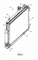
Fig. 4 is a perspective view of a heat exchange device of a comparative embodiment. -
Fig. 5 is a perspective view of a heat exchange device of a comparative embodiment. -
Fig. 6 is a perspective view of a heat exchange device of a modified example of the present embodiment. -
Fig. 7 is a perspective view of a heat exchange device of a modified example of the present embodiment. -
Fig. 8A is a perspective view of the first side plate and the header tank of a modified example of the present embodiment. -
Fig. 8B is a horizontally sectional view of the first side plate and the header tank of the modified example of the present embodiment. -
Fig. 9A is a perspective view of the first side plate and the header tank of a modified example of the present embodiment. -
Fig. 9B is a horizontally sectional view of the first side plate and the header tank of the modified example of the present embodiment. -
Fig. 10A is a perspective view of the first side plate and the header tank of a modified example of the present embodiment. -
Fig. 10B is a horizontally sectional view of the first side plate and the header tank of the modified example of the present embodiment. - A heat exchange device 1 of a first embodiment of the present invention will be described with reference to the drawings.
-
Fig. 1 is a perspective view of the heat exchange device 1 for a vehicle.Fig. 2 is an enlarged perspective view of the upper end side of the heat exchange device 1. - The heat exchange device 1 includes a
radiator 2 and acondenser 3. Theradiator 2 and thecondenser 3 are arranged in parallel along the flow direction of running wind. The heat exchange device 1 to be mounted in the vehicle will be described herein. However, the present invention is not limited to this but only requires a plurality of heat exchangers such as theradiator 2 and thecondenser 3 to be arranged in parallel along the air flow direction. - The
radiator 2 includesradiator tanks 20, afirst core portion 21, andfirst side plates 22. - Each of the
radiator tanks 20 includes ametal plate 23, aresin tank body 24, andattachment portions 25 for attaching theradiator 2 and thecondenser 3 to a vehicle body. Thetank body 24 and theplate 23 are integrated by swaging and fixing a part of theplate 23 to thetank body 24. - The
first core portion 21 includesfirst tubes 26 andfirst fins 27. Thefirst tubes 26 extend along the vertical direction and have ends communicating with theplates 23 of theradiator tanks 20. The plurality offirst tube 26 is arranged along the horizontal direction, and each of thefirst fins 27 is provided between the adjacentfirst tubes 26. In thefirst core portion 21, the first cooling water (fluid) whose temperature is increased by cooling for example an engine or the like flows through thefirst tubes 26, and the first cooling water is cooled by performing heat exchange with the air flowing outside thefirst tubes 26. By providing thefirst fins 27, a cooling performance in thefirst core portion 21 can be improved. - The
first side plates 22 extend along the longitudinal direction of thefirst tubes 26, that is, along the vertical direction, and are arranged on the both end sides of thefirst core portion 21. Thefirst side plates 22 are bonded to theradiator tanks 20 to reinforce thefirst core portion 21. Thefirst side plates 22 are made of metal and integrated withheader tanks 30 to be described later. - The
condenser 3 includes theheader tanks 30, asecond core portion 31, andsecond side plates 32. - The
header tanks 30 are made of metal and integrated with thefirst side plates 22 of theradiator 2. - The
second core portion 31 includessecond tubes 33 andsecond fins 34. Thesecond tubes 33 extend along the horizontal direction and have ends communicating with theheader tanks 30. The plurality ofsecond tubes 33 is arranged along the vertical direction, and each of thesecond fins 34 is provided between the adjacentsecond tubes 33. In thesecond core portion 31, a cooling medium (fluid) pressurized by a compressor or the like (not shown) flows through thesecond tubes 33, and the cooling medium is cooled and liquefied by performing heat exchange with the air flowing outside. By providing thesecond fins 34, a cooling performance in thesecond core portion 31 can be improved. It should be noted that the longitudinal direction of thefirst tubes 26 and the longitudinal direction of thesecond tubes 33 are different by 90 degrees, and points where thefirst tubes 26 and thesecond tubes 33 are in contact with each other are bonded by brazing. Thereby, theradiator 2 and thecondenser 3 can be bonded to each other by bonding thefirst core portion 21 of theradiator 2 and thesecond core portion 31 of thecondenser 3. - It should be noted that an application example that strength of the entire core is enhanced by bonding the points where the
first tubes 26 and thesecond tubes 33 are in contact with each other by brazing is shown in the present embodiment. However, thefirst tubes 26 and thesecond tubes 33 are not necessarily bonded to each other by brazing. Further, thefirst tubes 26 and thesecond tubes 33 are not necessarily in contact with each other. Thefirst tubes 26 and thesecond tubes 33 may be arranged at right angles in a non-contact state where a gap is provided between the tubes. - The
second side plates 32 extend along the longitudinal direction of thesecond tubes 33, that is, along the horizontal direction, and are arranged on the both end sides of thesecond core portion 31. Thesecond side plates 32 are bonded to theheader tanks 30 to reinforce thesecond core portion 31. -
Fig. 3 shows a horizontally sectional view of thefirst side plate 22 and theheader tank 30. In the present embodiment, by bending one metal plate and brazing an end of the plate bent into a tubular shape, thetubular header tank 30 is integrated with thefirst side plate 22 as shown inFig. 3 . - In the present embodiment, the metal
first side plates 22, theheader tanks 30, thefirst core portion 21, thesecond core portion 31, thesecond side plates 32, and the like are assembled while arranging a brazing material, and then brought into a heating furnace and heated, so that the brazing material is melted and the parts are brazed. In such a way, theradiator 2 is integrated with thecondenser 3. - In a case where the present embodiment is not used and a
radiator 40 and acondenser 41 are respectively attached to a vehicle body without integrating theradiator 40 with thecondenser 41,attachment portions 42 of theradiator 40 andattachment portions 43 of thecondenser 41 are respectively required as shown inFig. 4 . Thus, the number of parts is increased to increase weight. Theradiator 40 and thecondenser 41 are attached to the vehicle body after individually forming the radiator and the condenser. Thus, the processing man-hour is increased, so that working efficiency is deteriorated. Further, since a space for providing theattachment portions heat exchange device 45 cannot be downsized. - As shown in
Fig. 5 , aradiator 50 and acondenser 51 which are individually formed can be integrated with each other viaconnection members 52. However, in this case, theconnection members 52 are required, so that the number of parts is increased to increase weight. In addition, the processing man-hour is increased, so that working efficiency is deteriorated. Furthermore, since a space for providing theconnection members 52 is required, aheat exchange device 53 cannot be downsized. - In contrast, in the present embodiment, by integrating the
first side plates 22 with theheader tanks 30, the number of the attachment portions can be reduced. Since theradiator 2 can be integrated with thecondenser 3 without using theconnection members 52, the number of parts can be reduced to decrease weight. In addition, the processing man-hour is decreased, so that working efficiency can be improved. Furthermore, the heat exchange device 1 can be downsized. - Further, by integrating the
first side plates 22 with theheader tanks 30, bonding failure of theradiator 2 and thecondenser 3 is suppressed, so that theradiator 2 and thecondenser 3 can be stably attached to the vehicle body. - It should be noted that although the
first side plate 22 and theheader tank 30 are formed by processing one metal plate, the first side plate and the header tank may be formed by a plurality of parts. - Although the
radiator tank 20 using theresin tank body 24 is used, ametal radiator tank 20 may be used as shown inFig. 6 . As shown inFig. 7 , themetal radiator tank 20 may be integrated with thesecond side plate 32 of thecondenser 3. By this, the same effect as the present embodiment can also be obtained. - The
first side plates 22 may be integrated with theheader tanks 30 and further, theradiator tanks 20 may be integrated with thesecond side plates 32. Thereby, theradiator 2 and thecondenser 3 can be further stably attached to the vehicle body. - The
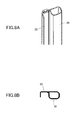
first side plate 22 and theheader tank 30 may be formed as shown inFigs. 8A and 8B. Fig. 8A is a perspective view of thefirst side plate 22 and theheader tank 30, andFig. 8B is a horizontally sectional view. An end of a plate bent into a tubular shape is bent outward and bonded to form theheader tank 30. - Further, as shown in
Figs. 9A and 9B , aprojection portion 60 may be formed in the end of thefirst side plate 22 and theprojection portion 60 may be inserted into ahole 61.Fig. 9A is a perspective view of thefirst side plate 22 and theheader tank 30, andFig. 9B is a horizontally sectional view. Further, as shown inFigs. 10A and 10B , a part of a point forming thefirst side plate 22 may be bent toward theheader tank 30 and the end of the plate bent into a tubular shape may be held by thebent portions 62 from the outer side.Fig. 10A is a perspective view of thefirst side plate 22 and theheader tank 30, andFig. 10B is a horizontally sectional view. From these, a spring back of the tubular plate can be prevented, so that the bonding failure at the time of brazing can be suppressed. - The embodiment of the present invention is described above. However, the above embodiment does not limit the technical scope of the present invention to the specific configurations of the above embodiment but only shows a part of the application example of the present invention.
- The present application claims priority based on Japanese Patent Application No.
2013-144765
Claims (5)
- A heat exchange device (1) in which a first heat exchanger (2) and a second heat exchanger (3) are arranged in parallel along the air flow direction, wherein
a side plate (22) of the first heat exchanger (2) is integrated with a tank (30) communicating with tubes (33) of the second heat exchanger (3) through which a fluid flows. - The heat exchange device (1) according to claim 1, wherein
a tank (20) communicating with tubes (26) of the first heat exchanger (2) through which a fluid flows is integrated with a side plate (32) of the second heat exchanger (3). - The heat exchange device (1) according to claim 1 or 2, wherein
at least one of the tank (20) communicating with the tubes (26) of the first heat exchanger (2) through which the fluid flows and the tank (30) of the second heat exchanger (3) is formed by bending a metal plate (22), and an engagement portion (60, 62) that prevents the bent metal plate (22) from a spring back is provided. - The heat exchange device (1) according to any one of claims 1 to 3, wherein
the tubes (26) through which the fluid of the first heat exchanger (2) flows and the tubes (33) of the second heat exchanger (3) are bonded to each other. - The heat exchange device (1) according to any one of claims 1 to 4, wherein
a fin (27, 34) is provided in at least one of a part between the adjacent tubes (26) of the first heat exchanger (2) and a part between the adjacent tubes (33) of the second heat exchanger (3).
Applications Claiming Priority (1)
| Application Number | Priority Date | Filing Date | Title |
|---|---|---|---|
| JP2013144765A JP6106546B2 (en) | 2013-07-10 | 2013-07-10 | Heat exchanger |
Publications (2)
| Publication Number | Publication Date |
|---|---|
| EP2824411A2 true EP2824411A2 (en) | 2015-01-14 |
| EP2824411A3 EP2824411A3 (en) | 2015-04-22 |
Family
ID=51211013
Family Applications (1)
| Application Number | Title | Priority Date | Filing Date |
|---|---|---|---|
| EP20140175589 Withdrawn EP2824411A3 (en) | 2013-07-10 | 2014-07-03 | Heat exchange device |
Country Status (3)
| Country | Link |
|---|---|
| EP (1) | EP2824411A3 (en) |
| JP (1) | JP6106546B2 (en) |
| CN (1) | CN204077300U (en) |
Cited By (1)
| Publication number | Priority date | Publication date | Assignee | Title |
|---|---|---|---|---|
| CN113124587A (en) * | 2019-12-31 | 2021-07-16 | 浙江盾安热工科技有限公司 | Heat exchanger |
Family Cites Families (9)
| Publication number | Priority date | Publication date | Assignee | Title |
|---|---|---|---|---|
| JP3051479B2 (en) * | 1991-03-15 | 2000-06-12 | 昭和アルミニウム株式会社 | Brazing method of mounting bracket for heat exchanger |
| JP3328108B2 (en) * | 1995-06-28 | 2002-09-24 | カルソニックカンセイ株式会社 | Pipe manufacturing method |
| JPH11223486A (en) * | 1997-12-04 | 1999-08-17 | Zexel:Kk | Side-by-side integrated heat exchanger and method of manufacturing the same |
| JPH11287590A (en) * | 1998-04-02 | 1999-10-19 | Calsonic Corp | Integrated heat exchanger |
| DE10257767A1 (en) * | 2002-12-10 | 2004-06-24 | Behr Gmbh & Co. Kg | Heat exchanger for condenser or gas cooler for air conditioning installations has two rows of channels for coolant with manifolds at ends and has ribs over which air can flow |
| JP2005106328A (en) * | 2003-09-29 | 2005-04-21 | Sanden Corp | Heat exchanging device |
| JP2009074739A (en) * | 2007-09-20 | 2009-04-09 | Calsonic Kansei Corp | Heat exchanging device for vehicle |
| US20120222848A1 (en) * | 2011-03-01 | 2012-09-06 | Visteon Global Technologies, Inc. | Integrated counter cross flow condenser |
| KR101353413B1 (en) * | 2011-09-22 | 2014-01-22 | 한라비스테온공조 주식회사 | Automotive Cooling Module |
-
2013
- 2013-07-10 JP JP2013144765A patent/JP6106546B2/en not_active Expired - Fee Related
-
2014
- 2014-07-03 EP EP20140175589 patent/EP2824411A3/en not_active Withdrawn
- 2014-07-08 CN CN201420375676.4U patent/CN204077300U/en not_active Expired - Fee Related
Non-Patent Citations (1)
| Title |
|---|
| None |
Cited By (2)
| Publication number | Priority date | Publication date | Assignee | Title |
|---|---|---|---|---|
| CN113124587A (en) * | 2019-12-31 | 2021-07-16 | 浙江盾安热工科技有限公司 | Heat exchanger |
| CN113124587B (en) * | 2019-12-31 | 2024-05-14 | 浙江盾安热工科技有限公司 | Heat exchanger |
Also Published As
| Publication number | Publication date |
|---|---|
| EP2824411A3 (en) | 2015-04-22 |
| JP6106546B2 (en) | 2017-04-05 |
| JP2015017744A (en) | 2015-01-29 |
| CN204077300U (en) | 2015-01-07 |
Similar Documents
| Publication | Publication Date | Title |
|---|---|---|
| JP6547576B2 (en) | Heat exchanger | |
| US10168109B2 (en) | Header plate for a heat exchanger, header box and heat exchanger | |
| US20150300757A1 (en) | Heat exchanger tube insert | |
| JP2008249252A (en) | Heat exchanger | |
| JP6439454B2 (en) | Heat exchanger | |
| JP5029166B2 (en) | Heat exchanger | |
| EP3134696B1 (en) | Vehicle heat exchanger tube and vehicle radiator comprising such a tube | |
| JP6123193B2 (en) | Refrigerant heat exchanger | |
| JPWO2017013918A1 (en) | Heat exchanger | |
| EP2469211A2 (en) | Multitubular heat exchanger | |
| CN103582797A (en) | Heat exchanger | |
| KR101971483B1 (en) | Heater | |
| JP2014169851A (en) | Heat exchanger | |
| JP2006284107A (en) | Heat exchanger | |
| JP2009228970A (en) | Heat exchanger | |
| JP6414504B2 (en) | Heat exchanger | |
| JP6106546B2 (en) | Heat exchanger | |
| CN106030235A (en) | Heat exchanger | |
| JP2017015352A (en) | Heat exchanger | |
| JP6083272B2 (en) | Heat exchanger | |
| CN110382990A (en) | Heat exchanger | |
| JP2014153006A (en) | Heat exchanger and method of manufacturing the same | |
| JP6874545B2 (en) | Heat exchanger | |
| JP6919472B2 (en) | Heat exchanger | |
| JP6102551B2 (en) | Manufacturing method of heat exchanger |
Legal Events
| Date | Code | Title | Description |
|---|---|---|---|
| 17P | Request for examination filed |
Effective date: 20140813 |
|
| AK | Designated contracting states |
Kind code of ref document: A2 Designated state(s): AL AT BE BG CH CY CZ DE DK EE ES FI FR GB GR HR HU IE IS IT LI LT LU LV MC MK MT NL NO PL PT RO RS SE SI SK SM TR |
|
| AX | Request for extension of the european patent |
Extension state: BA ME |
|
| PUAI | Public reference made under article 153(3) epc to a published international application that has entered the european phase |
Free format text: ORIGINAL CODE: 0009012 |
|
| PUAL | Search report despatched |
Free format text: ORIGINAL CODE: 0009013 |
|
| AK | Designated contracting states |
Kind code of ref document: A3 Designated state(s): AL AT BE BG CH CY CZ DE DK EE ES FI FR GB GR HR HU IE IS IT LI LT LU LV MC MK MT NL NO PL PT RO RS SE SI SK SM TR |
|
| AX | Request for extension of the european patent |
Extension state: BA ME |
|
| RIC1 | Information provided on ipc code assigned before grant |
Ipc: F28F 9/02 20060101AFI20150318BHEP Ipc: F28D 1/04 20060101ALI20150318BHEP Ipc: F25B 39/04 20060101ALI20150318BHEP Ipc: F28D 1/053 20060101ALI20150318BHEP |
|
| 17Q | First examination report despatched |
Effective date: 20151209 |
|
| RIC1 | Information provided on ipc code assigned before grant |
Ipc: F25B 39/04 20060101ALI20180808BHEP Ipc: F28D 1/053 20060101ALI20180808BHEP Ipc: F28F 9/00 20060101ALI20180808BHEP Ipc: F28F 9/02 20060101AFI20180808BHEP Ipc: F28D 21/00 20060101ALI20180808BHEP Ipc: F28D 1/04 20060101ALI20180808BHEP |
|
| GRAP | Despatch of communication of intention to grant a patent |
Free format text: ORIGINAL CODE: EPIDOSNIGR1 |
|
| INTG | Intention to grant announced |
Effective date: 20181008 |
|
| STAA | Information on the status of an ep patent application or granted ep patent |
Free format text: STATUS: THE APPLICATION IS DEEMED TO BE WITHDRAWN |
|
| 18D | Application deemed to be withdrawn |
Effective date: 20190219 |