EP2824314A2 - Starter-generator and method for controlling the same - Google Patents
Starter-generator and method for controlling the same Download PDFInfo
- Publication number
- EP2824314A2 EP2824314A2 EP20140175229 EP14175229A EP2824314A2 EP 2824314 A2 EP2824314 A2 EP 2824314A2 EP 20140175229 EP20140175229 EP 20140175229 EP 14175229 A EP14175229 A EP 14175229A EP 2824314 A2 EP2824314 A2 EP 2824314A2
- Authority
- EP
- European Patent Office
- Prior art keywords
- generator
- starter
- engine
- rotations
- voltage
- Prior art date
- Legal status (The legal status is an assumption and is not a legal conclusion. Google has not performed a legal analysis and makes no representation as to the accuracy of the status listed.)
- Withdrawn
Links
- 238000000034 method Methods 0.000 title claims description 8
- 238000004804 winding Methods 0.000 claims abstract description 34
- 239000007858 starting material Substances 0.000 claims abstract description 17
- 238000013459 approach Methods 0.000 claims abstract description 8
- 230000006870 function Effects 0.000 description 14
- 239000003990 capacitor Substances 0.000 description 12
- 230000000052 comparative effect Effects 0.000 description 6
- XEEYBQQBJWHFJM-UHFFFAOYSA-N Iron Chemical compound [Fe] XEEYBQQBJWHFJM-UHFFFAOYSA-N 0.000 description 4
- 230000008859 change Effects 0.000 description 2
- 238000001514 detection method Methods 0.000 description 2
- 238000010586 diagram Methods 0.000 description 2
- 229910052742 iron Inorganic materials 0.000 description 2
- 238000012986 modification Methods 0.000 description 2
- 230000004048 modification Effects 0.000 description 2
- 230000006978 adaptation Effects 0.000 description 1
- 230000004075 alteration Effects 0.000 description 1
- 230000006835 compression Effects 0.000 description 1
- 238000007906 compression Methods 0.000 description 1
- 238000011161 development Methods 0.000 description 1
- 230000000694 effects Effects 0.000 description 1
- 230000004907 flux Effects 0.000 description 1
- 230000014509 gene expression Effects 0.000 description 1
- 230000020169 heat generation Effects 0.000 description 1
- 230000007246 mechanism Effects 0.000 description 1
- 230000007935 neutral effect Effects 0.000 description 1
- 238000010248 power generation Methods 0.000 description 1
- 230000009467 reduction Effects 0.000 description 1
- 238000012546 transfer Methods 0.000 description 1
- 239000002699 waste material Substances 0.000 description 1
Images


Classifications
-
- F—MECHANICAL ENGINEERING; LIGHTING; HEATING; WEAPONS; BLASTING
- F02—COMBUSTION ENGINES; HOT-GAS OR COMBUSTION-PRODUCT ENGINE PLANTS
- F02N—STARTING OF COMBUSTION ENGINES; STARTING AIDS FOR SUCH ENGINES, NOT OTHERWISE PROVIDED FOR
- F02N11/00—Starting of engines by means of electric motors
- F02N11/04—Starting of engines by means of electric motors the motors being associated with current generators
-
- F—MECHANICAL ENGINEERING; LIGHTING; HEATING; WEAPONS; BLASTING
- F02—COMBUSTION ENGINES; HOT-GAS OR COMBUSTION-PRODUCT ENGINE PLANTS
- F02N—STARTING OF COMBUSTION ENGINES; STARTING AIDS FOR SUCH ENGINES, NOT OTHERWISE PROVIDED FOR
- F02N11/00—Starting of engines by means of electric motors
- F02N11/08—Circuits specially adapted for starting of engines
- F02N11/0859—Circuits specially adapted for starting of engines specially adapted to the type of the starter motor or integrated into it
-
- F—MECHANICAL ENGINEERING; LIGHTING; HEATING; WEAPONS; BLASTING
- F02—COMBUSTION ENGINES; HOT-GAS OR COMBUSTION-PRODUCT ENGINE PLANTS
- F02N—STARTING OF COMBUSTION ENGINES; STARTING AIDS FOR SUCH ENGINES, NOT OTHERWISE PROVIDED FOR
- F02N11/00—Starting of engines by means of electric motors
- F02N11/08—Circuits specially adapted for starting of engines
- F02N11/0862—Circuits specially adapted for starting of engines characterised by the electrical power supply means, e.g. battery
-
- F—MECHANICAL ENGINEERING; LIGHTING; HEATING; WEAPONS; BLASTING
- F02—COMBUSTION ENGINES; HOT-GAS OR COMBUSTION-PRODUCT ENGINE PLANTS
- F02N—STARTING OF COMBUSTION ENGINES; STARTING AIDS FOR SUCH ENGINES, NOT OTHERWISE PROVIDED FOR
- F02N11/00—Starting of engines by means of electric motors
- F02N11/08—Circuits specially adapted for starting of engines
- F02N2011/0881—Components of the circuit not provided for by previous groups
- F02N2011/0888—DC/DC converters
-
- F—MECHANICAL ENGINEERING; LIGHTING; HEATING; WEAPONS; BLASTING
- F02—COMBUSTION ENGINES; HOT-GAS OR COMBUSTION-PRODUCT ENGINE PLANTS
- F02N—STARTING OF COMBUSTION ENGINES; STARTING AIDS FOR SUCH ENGINES, NOT OTHERWISE PROVIDED FOR
- F02N11/00—Starting of engines by means of electric motors
- F02N11/08—Circuits specially adapted for starting of engines
- F02N2011/0881—Components of the circuit not provided for by previous groups
- F02N2011/0896—Inverters for electric machines, e.g. starter-generators
-
- F—MECHANICAL ENGINEERING; LIGHTING; HEATING; WEAPONS; BLASTING
- F02—COMBUSTION ENGINES; HOT-GAS OR COMBUSTION-PRODUCT ENGINE PLANTS
- F02N—STARTING OF COMBUSTION ENGINES; STARTING AIDS FOR SUCH ENGINES, NOT OTHERWISE PROVIDED FOR
- F02N19/00—Starting aids for combustion engines, not otherwise provided for
- F02N19/005—Aiding engine start by starting from a predetermined position, e.g. pre-positioning or reverse rotation
- F02N2019/007—Aiding engine start by starting from a predetermined position, e.g. pre-positioning or reverse rotation using inertial reverse rotation
-
- F—MECHANICAL ENGINEERING; LIGHTING; HEATING; WEAPONS; BLASTING
- F02—COMBUSTION ENGINES; HOT-GAS OR COMBUSTION-PRODUCT ENGINE PLANTS
- F02N—STARTING OF COMBUSTION ENGINES; STARTING AIDS FOR SUCH ENGINES, NOT OTHERWISE PROVIDED FOR
- F02N2200/00—Parameters used for control of starting apparatus
- F02N2200/02—Parameters used for control of starting apparatus said parameters being related to the engine
- F02N2200/022—Engine speed
Definitions
- the present invention relates to a starter-generator, particularly a starter-generator that serves as both an engine starter and a generator of various types of vehicles including motorcycles, and also relates to a method for controlling the starter-generator.
- a starter-generator that is mounted to a crankshaft of an engine of a motorcycle or the like and that serves as both a starter and a generator.
- the starter-generator functions as a starter motor that rotates the crankshaft to start the engine.
- the starter-generator is rotated by the crankshaft, to function as a generator.
- a starter-generator which is directly mounted to a crankshaft of an engine without interposition of a speed reduction mechanism, is required to generate a high torque at a time of engine start.
- a first override torque which means a torque for overriding the top dead center for the first time, and therefore a high torque exceeding this override torque is necessary for starting the engine.
- raising a drive voltage at a time of engine start to increase a starting torque of a starter motor is proposed in, for example, JP 2000-316299 A .
- a capacitor configured to be charged at a time of engine rotation is provided and the capacitor is connected in series with a battery at a time of engine start. Connecting the capacitor in series with the battery at a time of engine start raises a drive voltage of a starter-generator because a voltage charged in the capacitor is added to a voltage of the battery. The proposition states that this can provide a high torque exceeding the override torque necessary for starting the engine.
- An object of the present invention is to provide an engine starter-generator, particularly a starter-generator mounted to a crankshaft of an engine of a motorcycle, that enables efficient generation of a starting torque required at a time of engine start without causing an increase in the size of a stator, and also to provide a method for controlling the engine starter-generator.
- the present invention is based on the following findings of the inventors. Raising the drive voltage at a time of engine start as proposed above cannot always provide an expected high starting torque. Raising the drive voltage causes a large current to flow through a winding of a stator, but causes a magnetic saturation in a magnetic circuit of the stator. As a result, a torque that is proportionate to the drive voltage raised at a time of engine start cannot be obtained. In other words, the start energy inputted for starting the engine is not effectively used because of the magnetic saturation in the stator.
- a conceivable way to obtain a high starting torque that is proportionate to the raised drive voltage is enlarging the cross-sectional area of the stator so as to avoid occurrence of a magnetic saturation in the magnetic circuit.
- enlarging the cross-sectional area of the stator leads not only to an increase in the size of the device but also to an increase in an iron loss caused at a time of high-speed rotation of the engine.
- the starter-generator acts as a starter motor that causes a crankshaft of an engine to rotate from a predetermined rotation start position with an approach run given thereto, and after the engine start, acts as a generator.
- the starter-generator according to the present invention which causes the crankshaft of the engine to rotate from the predetermined rotation start position with an approach run given thereto at a time of engine start, has a so-called swing-back function.
- the swing-back function enables cranking to start at a position in a low-load region in a normal rotation direction of the engine. Therefore, even when a starting torque of the starter motor is relatively low, a high-load region near the compression top dead center can be overcome easily.
- the starter-generator includes a stator, a rotor, a driver, and a controller.
- the stator includes a winding.
- the rotor is mounted to the crankshaft, and arranged so as to be rotatable relative to the stator.
- the driver is connected to a battery that serves as a driving power source, and configured to control voltage application to the winding.
- the controller controls the driver.
- the controller controls the driver in the following manner.
- the controller controls the driver in such a manner that an application voltage applied to the winding is gradually raised such that the application voltage becomes a predetermined voltage that is higher than a terminal voltage of the battery at a time point when the number of rotations of the engine reaches a predetermined first number of rotations.
- the controller also controls the driver in such a manner that the raised application voltage is maintained at least until the engine is started.
- raising the application voltage applied to the winding at a time of engine start enables avoidance of an energy loss which may otherwise be caused by a magnetic saturation in the stator. As a result, only the energy that substantially contributes to an increase in the starting torque can be supplied effectively.
- the first number of rotations of the engine may be 400 rpm.
- the second number of rotations may be 1200 rpm.
- the controller controls the driver in such a manner that the application voltage is raised in accordance with the number of rotations of the engine until a time point when the number of rotations of the engine reaches the first number of rotations.
- Such a control enables only the energy that substantially contributes to an increase in the starting torque to be efficiently supplied while avoiding occurrence of a magnetic saturation in a magnetic circuit of the stator.
- the controller controls the driver in such a manner that the raised application voltage is maintained while the number of rotations of the engine is between the first number of rotations and a second number of rotations that is greater than the first number of rotations. Accordingly, a torque necessary for starting the engine is maintained, so that the engine can be reliably started.
- the controller controls the driver in such a manner that, at a time of engine start, the crankshaft is once rotated in a reverse direction and then rotated in a normal direction from the predetermined rotation start position. Once rotating the crankshaft in the reverse direction and then rotating the crankshaft in the normal direction from the predetermined rotation start position eliminates the need of a high starting torque in starting the engine.
- a rotor of so-called outer rotor type which is arranged so as to surround an outer circumference of the stator, is suitably adopted.
- the rotor functions as a flywheel, too.
- the starter-generator further includes a sensor that detects the angle of rotation of the crankshaft, and the controller controls the driver based on an output signal supplied from the sensor.
- the driver one including a chopper circuit connected to the battery and an inverter circuit connected to chopper circuit is suitably adopted.
- the chopper circuit functions as both a voltage-raising chopper and a voltage-lowering chopper.
- the controller controls the driver in such a manner that, while the starter-generator is acting as a generator, the chopper circuit lowers a voltage applied to the battery during a high-speed rotation region in which the number of rotations of the engine exceeds a third number of rotations that is greater than the second number of rotations. This can suppress an excessive charging current being supplied to the battery.
- the controller controls the driver in such a manner that, while the starter-generator is acting as a generator, the chopper circuit lowers a voltage applied to the battery from and after a time point when a charging current supplied to the battery exceeds a predetermined value. This can suppress a charging current being supplied to the battery.
- Another aspect of the present invention provides a vehicle such as a motorcycle, including the starter-generator with any of the above-mentioned features.
- Still another aspect of the present invention provides a method for controlling a starter-generator configured to act as a starter motor at a time of engine start and act as a generator after the engine start.
- the method include: gradually raising an application voltage applied to a winding wound on a stator such that the application voltage becomes higher than a terminal voltage of a battery serving as a driving power source at a time point when the number of rotations of the engine reaches a predetermined first number of rotations; and maintaining the raised application voltage at least until the engine is started.
- the first number of rotations of the engine is set to 400 rpm, and the second number of rotations of the engine is set to 1200 rpm.
- the application voltage is raised in accordance with the number of rotations of the engine until a time point when the number of rotations of the engine reaches the first number of rotations. Desirably, the raised application voltage is maintained while the number of rotations of the engine is between the first number of rotations and a second number of rotations that is greater than the first number of rotations.
- a crankshaft of the engine is once rotated in a reverse direction and then rotated in a normal direction from a predetermined rotation start position.
- FIG. 1 is an outline cross-sectional view showing a starter-generator SG according to an embodiment of the present invention and an engine E including the starter-generator SG.
- the starter-generator SG is mounted to the engine E of, for example, a motorcycle. More specifically, the starter-generator SG is coupled to a crankshaft 5 of the engine E, and at a time of engine start, functions as a starter motor that rotates the crankshaft 5 to start the engine E. After the engine start, the starter-generator SG is rotated by the crankshaft 5, to function as a generator.
- Applications of the present invention are not limited to a starter-generator of a motorcycle engine. The present invention is applicable to starter-generators of various types of vehicles.
- the engine E of this embodiment includes a crank case 1, a cylinder 2, a piston 3, a connecting rod 4, and a crankshaft 5.
- the cylinder 2 is provided in the crank case 1.
- the piston 3 is slidably arranged in the cylinder 2.
- An upper end portion of the connecting rod 4 is coupled to the piston 3.
- the crankshaft 5 is rotatably arranged in the crank case 1.
- a lower end portion of the connecting rod 4 is coupled to the crankshaft 5.
- the starter-generator SG is mounted to the right end portion of the crankshaft 5.
- the starter-generator SG is configured to, at a time of engine start, function as a starter motor that rotates the crankshaft 5 to start the engine E, and after the engine start, be rotated by the crankshaft 5 to function as a generator. A description thereof will be given later.
- the engine E illustrated in this embodiment has the structure shown in FIG. 1 ; in the present invention, a specific configuration of an engine main body is not limited to the one illustrated in the embodiment.
- the starter-generator SG includes a rotor 20 and a stator 30.
- the rotor 20 includes a rotor main body 21 having a cylindrical shape with a bottom, and a field permanent magnet 22 fixed to the rotor main body 21.
- the rotor main body 21 is fixed to one end portion of the crankshaft 5, and configured to be freely rotatable integrally with the crankshaft 5.
- the rotor 20, which is directly coupled to the crankshaft 5 and rotatable together with the crankshaft 5, also functions as a flywheel of the engine E.
- the stator 30 includes a plurality of teeth 31 that integrally extend radially outward.
- the teeth 31 serve as salient poles.
- An armature winding 32 is wound around each tooth 31.
- a battery B serving as a driving power source is connected to the starter-generator SG via a driver 60. Transfer of electric power between the battery B and the starter-generator SG is made through a controller 70 which will be described later.
- the driver 60 of the starter-generator SG includes a chopper circuit 40 that is connected to the battery B and an inverter circuit 50 that is connected to the output side of the chopper circuit 40.
- the inverter circuit 50 which serves as a drive circuit for driving the starter-generator SG, is a bridge circuit including six switching elements, namely, FETs 51U, 51V, and 51W, and FETs 52U, 52V, and 52W, in a three-phase bridge connection.
- Each of diodes 53U, 53V, 53W, 54U, 54V, and 54W is connected across the drain and source of each of the FETs of the FET bridge circuit.
- the switching elements are not limited to FETs.
- MOS transistors may be adoptable as appropriate.
- Input terminals 50a and 50b of the inverter circuit 50 are connected to DC buses 10 and 11, respectively.
- Output terminals 55U, 55V, and 55W of the inverter circuit 50 are connected to terminals of windings 32U, 32V, and 32W of the stator 30 of the starter-generator SG, respectively.
- the other terminals of the windings 32U, 32V, and 32W are commonly connected.
- the DC bus 11 connected to one input terminal 50b of the inverter circuit 50 is connected to a negative terminal of the battery B.
- a capacitor 12 is connected across the input terminals 50a and 50b of the inverter circuit 50, that is, across the DC buses 10 and 11.
- the chopper circuit 40 includes two FETs 41 and 42 serving as switching elements.
- the FETs 41 and 42 which are connected in series with each other, are arranged across the input terminals 50a and 50b of the inverter circuit 50, that is, across the DC buses 10 and 11.
- Each of diodes 43 and 44 is connected across the drain and source of each of the FETs 41 and 42.
- a positive terminal of the battery B is connected via a coil 45 to the terminal of connection between the FETs 41 and 42, that is, to a neutral point of the chopper circuit 40.
- a voltage detector 13 is connected in parallel with the capacitor 12. This enables detection of a voltage (that is, an application voltage applied to the windings 32U, 32V, and 32W) of the input-side terminals of the inverter circuit 50.
- Output terminals of the voltage detector 13 and the position detector 14 are connected to the controller 70.
- the controller 70 controls the driver 60 that includes the chopper circuit 40 and the inverter circuit 50. More specifically, the controller 70 controls the driver 60 in the following manner.
- An application voltage applied to the windings 32U, 32V, and 32W is gradually raised such that the application voltage raised from a terminal voltage (for example, 12V) of the battery becomes a predetermined voltage (for example, 24V) that is higher than the terminal voltage at a time point when the number of rotations of the engine E reaches a predetermined first number of rotations.
- the application voltage thus raised is maintained at least until the engine E is started.
- the FET 42 makes a closed-loop circuit including the coil 45 and the FET 42.
- a current flows from the battery B to the coil 45.
- turning off the FET 42 causes energy accumulated in the coil 45 to be discharged through the diode 43.
- a raised voltage is applied to the capacitor 12.
- the rate of voltage rise is optionally controlled by the controller 70.
- the driver 60 is controlled such that a terminal voltage of the capacitor 12 gradually rises in accordance with the number of rotations of the rotor 20. A description thereof will be given later.
- the controller 70 controls a gate signal that is supplied to the FETs 51U, 51V, 51W, 52U, 52V, and 52W of the inverter circuit 50 based on a position detection signal supplied from the position detector 14.
- the FETs 51U, 51V, 51W, 52U, 52V, and 52W are sequentially turned on/off. This causes a current to flow through the windings 32U, 32V, and 32W of the stator of the starter-generator SG, so that the rotor 20 is rotated.
- the starter-generator SG Upon start of the starter-generator SG, the crankshaft 5 of the engine E rotates, to start the engine E. In the manner thus far described, the starter-generator SG functions as a starter of the engine E.
- the controller 70 stops supplying the gate signal to the gate of each of the FETs 51U, 51V, 51W, 52U, 52V, and 52W of the inverter circuit 50, to bring all the FETs into a turn-off state. In other words, the inverter circuit 50 is brought into a non-operation state. While the engine E is in operation, the starter-generator SG is rotated by the crankshaft 5. Therefore, a voltage is induced in the windings 32U, 32V, and 32W of the stator 30.
- the AC voltage thus induced in the windings 32U, 32V, and 32W is full-wave rectified by the diodes 53U, 53V, 53W, 54U, 54V, and 54W of the inverter circuit 50, to be converted into a DC voltage.
- the DC voltage is applied to the capacitor 12.
- the voltage applied to the capacitor 12 is applied to the battery B through the chopper circuit 40, so that the battery B is charged.
- the controller 70 controls on/off of the FET 41 of the chopper circuit 40, to make the chopper circuit 40 operate as a voltage-lowering chopper. That is, the controller 70 controls on/off of the FET 41 of the chopper circuit 40, to lower the voltage that is applied to the battery B.
- the controller 70 makes the chopper circuit 40 operate as a voltage-raising chopper, to raise the voltage that is applied to the windings 32U, 32V, and 32W of the stator 30.
- the controller 70 makes the chopper circuit 40 operate as a voltage-lowering chopper, to suppress current charging to the battery B.
- a specific control that the controller 70 makes on the driver 60 is as follows. At a time of engine start, an application voltage applied to the windings 32U, 32V, and 32W is gradually raised such that the application voltage raised from a terminal voltage (in this embodiment, 12V) of the battery B becomes a predetermined voltage (in this embodiment, 24V) that is higher than the terminal voltage at a time point when the number of rotations of the engine E reaches the predetermined first number of rotations. Then, the application voltage thus raised is maintained at least until the engine E is started.
- the reason why the application voltage applied to the windings 32U, 32V, and 32W of the stator 30 is raised gradually, not at once, such that the application voltage raised from the terminal voltage (in this embodiment, 12V) of the battery B becomes the predetermined voltage (in this embodiment, 24V) that is higher than the terminal voltage is as follows. As indicated by the alternate long and short dash line in FIG. 3 , raising the voltage from 12V to 24V at once when the engine E is started causes a current flowing through the windings 32U, 32V, and 32W to increase at once, as indicated by the alternate long and short dash line in FIG. 4 . The power also increases rapidly as indicated by the alternate long and short dash line in FIG. 5 . However, a starting torque (motor torque) does not increase in proportion to the increase in the current, because a magnetic saturation occurs in a magnetic circuit of the stator 30. That is, the inputted energy is partially consumed in the form of heat generation.
- the stator 30 has a sufficiently large cross-sectional area so as to prevent occurrence of a magnetic saturation in the magnetic circuit of the stator 30.
- enlarging the cross-sectional area of the stator 30 leads not only to an increase in the size of the device but also to an increase in an iron loss caused at a time of high-speed rotation.
- the application voltage applied to the windings 32U, 32V, and 32W of the stator 30 is raised gradually, not at once, such that the application voltage raised from the terminal voltage (in this embodiment, 12V) of the battery B becomes the predetermined voltage (in this embodiment, 24V) that is higher than the terminal voltage.
- the phrase "raise gradually” is not meant to be limited to raising the application voltage at a constant rate.
- the phrase should be construed to include, for example, raising the application voltage in a stepwise manner.
- raising the voltage at the beginning of engine start may not be indispensable.
- the terminal voltage (for example, 12V) of the battery B is applied without any change added thereto, so that the engine E is started, and then the application voltage applied to the windings 32U, 32V, and 32W is gradually raised to become the predetermined voltage (for example, 24V) by the time the number of rotations of the engine E reaches the predetermined first number of rotations.
- the point of the present invention is to exclude raising the voltage to a predetermined voltage (in this embodiment, 24V) at once when the engine is started.
- the starter-generator SG acts as a starter motor that causes the crankshaft 5 of the engine E to rotate from a predetermined rotation start position with an approach run given thereto, in order to start the engine E with overcoming of a first override torque which is a high torque. That is, a so-called swing-back function is used to overcome the high first override torque.
- the application voltage applied to the winding has a negative value, for the purpose of once causing reverse rotation of the crankshaft 5 to exert the swing-back function.
- the position detector 14 detects the position of the rotor 20, and the controller 70 controls the driver 60. Thereby, the crankshaft 5 of the engine E is once set at the predetermined rotation start position. Then, from the position, the engine E is started with an approach run given thereto.
- the chopper circuit 40 At the beginning of starting the engine E, the chopper circuit 40 is not operated, and the terminal voltage 12V of the battery B is applied to the inverter circuit 50 without any change, to start the starter-generator SG. Then, from and immediately after the beginning of engine start, the chopper circuit 40 is operated as a voltage-raising chopper, so that the application voltage applied to the input terminals 50a and 50b of the inverter circuit 50 is raised in accordance with the number of engine rotations.
- the controller 70 controls the driver 60 (chopper circuit 40) in such a manner that the application voltage applied to the input terminals 50a and 50b of the inverter circuit 50 is raised to 24V, which is twice the terminal voltage 12V of the battery B, at a time point when the number of rotations of the engine E reaches the predetermined first number of rotations, and then, the application voltage thus raised is maintained until the number of rotations of the engine E reaches a predetermined second number of rotations.
- the first number of rotations of the engine E is 400 rpm.
- the second number of rotations may be the one obtained after the beginning of starting the engine E.
- the second number of rotations is 1200 rpm. That is, in this embodiment, at a time of engine start, the application voltage is raised from 12V at a constant rate in proportion to the number of engine rotations such that the application voltage is 24V at a time point when the number of rotations of the engine E reaches 400 rpm. The state where the application voltage has been raised is maintained until a time point when the number of engine rotations reaches 1200 rpm. The engine E is started when the number of rotations of the engine E has a value between the first number of rotations 400 rpm and the second number of rotations 1200 rpm.
- a torque actually generated as a result of the control in which the application voltage is gradually raised such that it becomes a predetermined voltage (24V) at the time point when the number of rotations of the engine E reaches 400 rpm is almost the same as a torque generated in a case where the application voltage is raised to 24V at once. More specifically, the amount of inputted work was larger in a comparative example in which the application voltage was raised at once than in an example in which the application voltage was gradually raised as shown in FIG. 7 , but nevertheless a maximum torque generated was almost the same as shown in FIG. 6 . This reveals that gradually raising the application voltage ensures that the inputted energy can be used as the energy for torque generation without any waste. In a case of starting the engine E at 12V without raising the application voltage, as compared with a case of raising the application voltage, a torque was lowered from and immediately after the start.
- the controller 70 stops supplying the signal to the gate of each of the FETs 51U, 51V, 51W, 52U, 52V, and 52W of the inverter circuit 50, to bring all the FETs into the turn-off state. In other words, the inverter circuit 50 is brought into the non-operation state.
- the rotor 20 of the starter-generator SG is rotated by the crankshaft 5 of the engine E.
- the rotation of the rotor 20 around the stator 30 induces a voltage in each of the windings 32U, 32V, and 32W, because magnetic fluxes of the permanent magnet 22 mounted to the rotor 20 make interlinkage with each of the windings 32U, 32V, and 32W of the stator 30.
- the induced voltage is full-wave rectified by the diodes 53U, 53V, 53W, 54U, 54V, and 54W of the inverter circuit 50, and converted into a DC voltage.
- the DC voltage charges the battery B.
- the controller 70 controls the chopper circuit 40 such that the chopper circuit 40 operates as a voltage-lowering chopper, and thus overcharging of the battery B is prevented.
- the starter-generator SG acts as a starter motor that causes the crankshaft 5 of the engine E to rotate from the predetermined rotation start position with an approach run given thereto, as described above.
- the controller 70 gradually, not at once, raises the application voltage applied to the windings 32U, 32V, and 32W. This avoids occurrence of a magnetic saturation in the magnetic circuit of the stator 30, and thus the inputted energy can be efficiently used as a starting torque. Accordingly, the engine E can be efficiently started with use of the conventional battery B, without causing an increase in the size of the device.
- the controller 70 controls the driver 60 in an appropriate manner, so that overcharging of the battery B can be prevented.
- the above-described embodiment illustrates a case where the application voltage is raised to the voltage (24V) that is twice the voltage (12V) of the battery B, this is not limiting.
- the voltage of the battery B and the raised voltage can be optionally set as appropriate.
- a specific circuit configuration of the driver 60 is not limited to the embodiment illustrated herein, and any other circuit configurations are adoptable.
- the raised application voltage is not limited to the voltage at a time point when the number of rotations of the engine reaches the first number of rotations and can be a voltage that is raised higher than at least the terminal voltage of the battery.
- the raised application voltage is the same as or substantially the same as the voltage at a time point when the number of rotations of the engine reaches the first number of rotations.
- the raised application voltage is maintained at a fixed value (24V) at least until the engine is started.
- the present invention is not limited to the embodiment.
- the raised application voltage can be maintained at a substantially fixed value.
- maintaining the raised application voltage can include maintaining a state where the application voltage has been raised higher than the terminal voltage of the battery at least until the engine is started. In this case, the raised application voltage can be changed as long as it is kept higher than the terminal voltage of the battery.
- the present invention may be embodied in many different forms.
- the present disclosure is to be considered as providing examples of the principles of the invention.
- a number of illustrative embodiments are described herein with the understanding that such examples are not intended to limit the invention to preferred embodiments described herein and/or illustrated herein.
- the present invention is applicable as a starter-generator that is mounted to a engine of, for example, a motorcycle.
Landscapes
- Engineering & Computer Science (AREA)
- Chemical & Material Sciences (AREA)
- Combustion & Propulsion (AREA)
- Mechanical Engineering (AREA)
- General Engineering & Computer Science (AREA)
- Control Of Eletrric Generators (AREA)
- Combined Controls Of Internal Combustion Engines (AREA)
Abstract
Description
- The present invention relates to a starter-generator, particularly a starter-generator that serves as both an engine starter and a generator of various types of vehicles including motorcycles, and also relates to a method for controlling the starter-generator.
- Conventionally known is a starter-generator that is mounted to a crankshaft of an engine of a motorcycle or the like and that serves as both a starter and a generator. At a time of engine start, the starter-generator functions as a starter motor that rotates the crankshaft to start the engine. After the engine start, the starter-generator is rotated by the crankshaft, to function as a generator.
- A starter-generator, which is directly mounted to a crankshaft of an engine without interposition of a speed reduction mechanism, is required to generate a high torque at a time of engine start. At a time of engine start, particularly, it is necessary that the engine exerts a high torque as a first override torque which means a torque for overriding the top dead center for the first time, and therefore a high torque exceeding this override torque is necessary for starting the engine. For this purpose, raising a drive voltage at a time of engine start to increase a starting torque of a starter motor is proposed in, for example,
JP 2000-316299 A - To be specific, it is proposed that a capacitor configured to be charged at a time of engine rotation is provided and the capacitor is connected in series with a battery at a time of engine start. Connecting the capacitor in series with the battery at a time of engine start raises a drive voltage of a starter-generator because a voltage charged in the capacitor is added to a voltage of the battery. The proposition states that this can provide a high torque exceeding the override torque necessary for starting the engine.
- An object of the present invention is to provide an engine starter-generator, particularly a starter-generator mounted to a crankshaft of an engine of a motorcycle, that enables efficient generation of a starting torque required at a time of engine start without causing an increase in the size of a stator, and also to provide a method for controlling the engine starter-generator.
- This object is achieved by an engine starter-generator according to claim 1, and by a method according to
claim 15 - The present invention is based on the following findings of the inventors. Raising the drive voltage at a time of engine start as proposed above cannot always provide an expected high starting torque. Raising the drive voltage causes a large current to flow through a winding of a stator, but causes a magnetic saturation in a magnetic circuit of the stator. As a result, a torque that is proportionate to the drive voltage raised at a time of engine start cannot be obtained. In other words, the start energy inputted for starting the engine is not effectively used because of the magnetic saturation in the stator.
- A conceivable way to obtain a high starting torque that is proportionate to the raised drive voltage is enlarging the cross-sectional area of the stator so as to avoid occurrence of a magnetic saturation in the magnetic circuit. However, enlarging the cross-sectional area of the stator leads not only to an increase in the size of the device but also to an increase in an iron loss caused at a time of high-speed rotation of the engine.
- Thus, in conventional approaches described in the technical background above, there remains a demand for development of an engine starter-generator that enables efficient generation of a starting torque without causing an increase in the size of a stator.
- The above object and other objects and advantageous effects of the present invention will become more apparent from the preferred embodiment described later.
- In the following, a starter-generator according to the present invention will be described.
- The starter-generator, at a time of engine start, acts as a starter motor that causes a crankshaft of an engine to rotate from a predetermined rotation start position with an approach run given thereto, and after the engine start, acts as a generator. In other words, the starter-generator according to the present invention, which causes the crankshaft of the engine to rotate from the predetermined rotation start position with an approach run given thereto at a time of engine start, has a so-called swing-back function. The swing-back function enables cranking to start at a position in a low-load region in a normal rotation direction of the engine. Therefore, even when a starting torque of the starter motor is relatively low, a high-load region near the compression top dead center can be overcome easily.
- The starter-generator includes a stator, a rotor, a driver, and a controller. The stator includes a winding. The rotor is mounted to the crankshaft, and arranged so as to be rotatable relative to the stator. The driver is connected to a battery that serves as a driving power source, and configured to control voltage application to the winding. The controller controls the driver.
- At a time of engine start, the controller controls the driver in the following manner. The controller controls the driver in such a manner that an application voltage applied to the winding is gradually raised such that the application voltage becomes a predetermined voltage that is higher than a terminal voltage of the battery at a time point when the number of rotations of the engine reaches a predetermined first number of rotations. The controller also controls the driver in such a manner that the raised application voltage is maintained at least until the engine is started. Gradually, not at once, raising the application voltage applied to the winding at a time of engine start enables avoidance of an energy loss which may otherwise be caused by a magnetic saturation in the stator. As a result, only the energy that substantially contributes to an increase in the starting torque can be supplied effectively.
- In a preferable example, the first number of rotations of the engine may be 400 rpm. In a preferable example, the second number of rotations may be 1200 rpm.
- Desirably, the controller controls the driver in such a manner that the application voltage is raised in accordance with the number of rotations of the engine until a time point when the number of rotations of the engine reaches the first number of rotations. Such a control enables only the energy that substantially contributes to an increase in the starting torque to be efficiently supplied while avoiding occurrence of a magnetic saturation in a magnetic circuit of the stator.
- Preferably, the controller controls the driver in such a manner that the raised application voltage is maintained while the number of rotations of the engine is between the first number of rotations and a second number of rotations that is greater than the first number of rotations. Accordingly, a torque necessary for starting the engine is maintained, so that the engine can be reliably started.
- Preferably, the controller controls the driver in such a manner that, at a time of engine start, the crankshaft is once rotated in a reverse direction and then rotated in a normal direction from the predetermined rotation start position. Once rotating the crankshaft in the reverse direction and then rotating the crankshaft in the normal direction from the predetermined rotation start position eliminates the need of a high starting torque in starting the engine.
- As the rotor, a rotor of so-called outer rotor type, which is arranged so as to surround an outer circumference of the stator, is suitably adopted. In such a case, the rotor functions as a flywheel, too.
- It may be acceptable that the starter-generator further includes a sensor that detects the angle of rotation of the crankshaft, and the controller controls the driver based on an output signal supplied from the sensor.
- As the driver, one including a chopper circuit connected to the battery and an inverter circuit connected to chopper circuit is suitably adopted. In such a case, the chopper circuit functions as both a voltage-raising chopper and a voltage-lowering chopper.
- Preferably, the controller controls the driver in such a manner that, while the starter-generator is acting as a generator, the chopper circuit lowers a voltage applied to the battery during a high-speed rotation region in which the number of rotations of the engine exceeds a third number of rotations that is greater than the second number of rotations. This can suppress an excessive charging current being supplied to the battery.
- It may be acceptable that the controller controls the driver in such a manner that, while the starter-generator is acting as a generator, the chopper circuit lowers a voltage applied to the battery from and after a time point when a charging current supplied to the battery exceeds a predetermined value. This can suppress a charging current being supplied to the battery.
- Another aspect of the present invention provides a vehicle such as a motorcycle, including the starter-generator with any of the above-mentioned features.
- Still another aspect of the present invention provides a method for controlling a starter-generator configured to act as a starter motor at a time of engine start and act as a generator after the engine start. The method include: gradually raising an application voltage applied to a winding wound on a stator such that the application voltage becomes higher than a terminal voltage of a battery serving as a driving power source at a time point when the number of rotations of the engine reaches a predetermined first number of rotations; and maintaining the raised application voltage at least until the engine is started.
- Preferably, the first number of rotations of the engine is set to 400 rpm, and the second number of rotations of the engine is set to 1200 rpm.
- It may be acceptable that the application voltage is raised in accordance with the number of rotations of the engine until a time point when the number of rotations of the engine reaches the first number of rotations. Desirably, the raised application voltage is maintained while the number of rotations of the engine is between the first number of rotations and a second number of rotations that is greater than the first number of rotations.
- Desirably, at a time of engine start, a crankshaft of the engine is once rotated in a reverse direction and then rotated in a normal direction from a predetermined rotation start position.
- It may be acceptable that:
- the battery is connected to a chopper circuit,
- while the starter-generator is acting as a generator after the engine start, the chopper circuit is caused to lower a voltage applied to the battery when the number of rotations of the engine exceeds a third number of rotations.
- It may be acceptable that:
- a chopper circuit is connected to the battery,
- while the starter-generator is acting as a generator after the engine start, the chopper circuit is caused to lower a voltage applied to the battery when a charging current supplied to the battery exceeds a predetermined value.
-
-
FIG. 1 is a cross-sectional view showing an outline configuration of a starter-generator according to an embodiment of the present invention and an engine having the starter-generator mounted thereto. -
FIG. 2 is a diagram showing an electrical configuration of the starter-generator. -
FIG. 3 is a graph showing a control of a voltage applied to windings of a starter-generator in an example in which an application voltage applied to windings of a starter-generator was controlled based on the present invention, a comparative example in which an application voltage was raised at once, and a reference example in which an application voltage was not raised. -
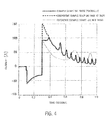
FIG. 4 is a graph showing a variation in the current that flowed through the windings of the starter-generator in the example, the comparative example, and the reference example. -
FIG. 5 is a graph showing a variation in the power in the example, the comparative example, and the reference example. -
FIG. 6 is a graph showing a variation in the torque of the starter-generator in the example, the comparative example, and the reference example. -
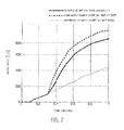
FIG. 7 is a graph showing a variation in the amount of work inputted in the example, the comparative example, and the reference example. -
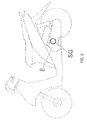
FIG. 8 is an explanatory diagram showing an example of a vehicle that includes the starter-generator. - Hereinafter, the present invention will be described based on a preferred embodiment with reference to the drawings.
-
FIG. 1 is an outline cross-sectional view showing a starter-generator SG according to an embodiment of the present invention and an engine E including the starter-generator SG. - Firstly, with reference to
FIG. 1 , a description will be given to outline configurations of the starter-generator SG of this embodiment and the engine E to which the starter-generator SG is mounted. - As shown in
FIG. 1 , the starter-generator SG according to this embodiment is mounted to the engine E of, for example, a motorcycle. More specifically, the starter-generator SG is coupled to acrankshaft 5 of the engine E, and at a time of engine start, functions as a starter motor that rotates thecrankshaft 5 to start the engine E. After the engine start, the starter-generator SG is rotated by thecrankshaft 5, to function as a generator. Applications of the present invention are not limited to a starter-generator of a motorcycle engine. The present invention is applicable to starter-generators of various types of vehicles. - The engine E of this embodiment includes a crank case 1, a
cylinder 2, apiston 3, a connectingrod 4, and acrankshaft 5. Thecylinder 2 is provided in the crank case 1. Thepiston 3 is slidably arranged in thecylinder 2. An upper end portion of the connectingrod 4 is coupled to thepiston 3. Thecrankshaft 5 is rotatably arranged in the crank case 1. A lower end portion of the connectingrod 4 is coupled to thecrankshaft 5. - A right end portion of the
crankshaft 5 extends and protrudes out of the crank case 1. The starter-generator SG is mounted to the right end portion of thecrankshaft 5. The starter-generator SG is configured to, at a time of engine start, function as a starter motor that rotates thecrankshaft 5 to start the engine E, and after the engine start, be rotated by thecrankshaft 5 to function as a generator. A description thereof will be given later. - Although the engine E illustrated in this embodiment has the structure shown in
FIG. 1 ; in the present invention, a specific configuration of an engine main body is not limited to the one illustrated in the embodiment. - As shown in
FIG. 1 , the starter-generator SG includes arotor 20 and astator 30. - The
rotor 20 includes a rotormain body 21 having a cylindrical shape with a bottom, and a fieldpermanent magnet 22 fixed to the rotormain body 21. The rotormain body 21 is fixed to one end portion of thecrankshaft 5, and configured to be freely rotatable integrally with thecrankshaft 5. Therotor 20, which is directly coupled to thecrankshaft 5 and rotatable together with thecrankshaft 5, also functions as a flywheel of the engine E. - The
stator 30 includes a plurality ofteeth 31 that integrally extend radially outward. Theteeth 31 serve as salient poles. An armature winding 32 is wound around eachtooth 31. - A battery B serving as a driving power source is connected to the starter-generator SG via a
driver 60. Transfer of electric power between the battery B and the starter-generator SG is made through acontroller 70 which will be described later. - A specific configuration of the
driver 60 will be described with reference toFIG. 2 . Thedriver 60 of the starter-generator SG includes a chopper circuit 40 that is connected to the battery B and aninverter circuit 50 that is connected to the output side of the chopper circuit 40. Theinverter circuit 50, which serves as a drive circuit for driving the starter-generator SG, is a bridge circuit including six switching elements, namely,FETs FETs diodes -
Input terminals inverter circuit 50 are connected toDC buses Output terminals inverter circuit 50 are connected to terminals ofwindings stator 30 of the starter-generator SG, respectively. The other terminals of thewindings - The
DC bus 11 connected to oneinput terminal 50b of theinverter circuit 50 is connected to a negative terminal of the batteryB. A capacitor 12 is connected across theinput terminals inverter circuit 50, that is, across theDC buses - The chopper circuit 40 includes two
FETs 41 and 42 serving as switching elements. TheFETs 41 and 42, which are connected in series with each other, are arranged across theinput terminals inverter circuit 50, that is, across theDC buses diodes 43 and 44 is connected across the drain and source of each of theFETs 41 and 42. A positive terminal of the battery B is connected via acoil 45 to the terminal of connection between theFETs 41 and 42, that is, to a neutral point of the chopper circuit 40. - A
voltage detector 13 is connected in parallel with thecapacitor 12. This enables detection of a voltage (that is, an application voltage applied to thewindings inverter circuit 50. Aposition detector 14, which is provided in the starter-generator SG, detects the rotational position of therotor 20. - Output terminals of the
voltage detector 13 and theposition detector 14 are connected to thecontroller 70. Thecontroller 70 controls thedriver 60 that includes the chopper circuit 40 and theinverter circuit 50. More specifically, thecontroller 70 controls thedriver 60 in the following manner. An application voltage applied to thewindings - Firstly, operations of the
driver 60 and thecontroller 70 in a case where the starter-generator SG acts as a starter will be described. When the chopper circuit 40 is in a non-operation state, the voltage of the battery B is applied to thecapacitor 12 via thecoil 45 and thediode 43. In this embodiment, the battery B of 12V is adopted, and therefore thecapacitor 12 is charged to 12V. Thecontroller 70 controls a gate signal that is supplied to theFET 42 included in the chopper circuit 40, to turn on/off theFET 42. - Turning on the
FET 42 makes a closed-loop circuit including thecoil 45 and theFET 42. Thus, a current flows from the battery B to thecoil 45. Then, turning off theFET 42 causes energy accumulated in thecoil 45 to be discharged through thediode 43. As a result, a raised voltage is applied to thecapacitor 12. The rate of voltage rise is optionally controlled by thecontroller 70. In this embodiment, thedriver 60 is controlled such that a terminal voltage of thecapacitor 12 gradually rises in accordance with the number of rotations of therotor 20. A description thereof will be given later. - The
controller 70 controls a gate signal that is supplied to theFETs inverter circuit 50 based on a position detection signal supplied from theposition detector 14. As a result, theFETs windings rotor 20 is rotated. - Upon start of the starter-generator SG, the
crankshaft 5 of the engine E rotates, to start the engine E. In the manner thus far described, the starter-generator SG functions as a starter of the engine E. - Next, operations of the
driver 60 and thecontroller 70 in a case where the starter-generator SG acts as a generator will be described. - After the engine E is started, the
controller 70 stops supplying the gate signal to the gate of each of theFETs inverter circuit 50, to bring all the FETs into a turn-off state. In other words, theinverter circuit 50 is brought into a non-operation state. While the engine E is in operation, the starter-generator SG is rotated by thecrankshaft 5. Therefore, a voltage is induced in thewindings stator 30. The AC voltage thus induced in thewindings diodes inverter circuit 50, to be converted into a DC voltage. The DC voltage is applied to thecapacitor 12. - The voltage applied to the
capacitor 12 is applied to the battery B through the chopper circuit 40, so that the battery B is charged. Here, in a case where the number of rotations of the engine E is large, a greater AC voltage is induced, which may overcharge the battery B. To prevent such overcharging of the battery B, thecontroller 70 controls on/off of the FET 41 of the chopper circuit 40, to make the chopper circuit 40 operate as a voltage-lowering chopper. That is, thecontroller 70 controls on/off of the FET 41 of the chopper circuit 40, to lower the voltage that is applied to the battery B. - Thus, at a time of engine start, the
controller 70 makes the chopper circuit 40 operate as a voltage-raising chopper, to raise the voltage that is applied to thewindings stator 30. After the engine start, thecontroller 70 makes the chopper circuit 40 operate as a voltage-lowering chopper, to suppress current charging to the battery B. - In this embodiment, a specific control that the
controller 70 makes on thedriver 60 is as follows. At a time of engine start, an application voltage applied to thewindings - The reason why the application voltage applied to the
windings stator 30 is raised gradually, not at once, such that the application voltage raised from the terminal voltage (in this embodiment, 12V) of the battery B becomes the predetermined voltage (in this embodiment, 24V) that is higher than the terminal voltage is as follows. As indicated by the alternate long and short dash line inFIG. 3 , raising the voltage from 12V to 24V at once when the engine E is started causes a current flowing through thewindings FIG. 4 . The power also increases rapidly as indicated by the alternate long and short dash line inFIG. 5 . However, a starting torque (motor torque) does not increase in proportion to the increase in the current, because a magnetic saturation occurs in a magnetic circuit of thestator 30. That is, the inputted energy is partially consumed in the form of heat generation. - To increase the starting torque in proportion to the increase in the current, it is necessary that the
stator 30 has a sufficiently large cross-sectional area so as to prevent occurrence of a magnetic saturation in the magnetic circuit of thestator 30. However, enlarging the cross-sectional area of thestator 30 leads not only to an increase in the size of the device but also to an increase in an iron loss caused at a time of high-speed rotation. To solve such problems, in the embodiment of the present invention, at a time of engine start, the application voltage applied to thewindings stator 30 is raised gradually, not at once, such that the application voltage raised from the terminal voltage (in this embodiment, 12V) of the battery B becomes the predetermined voltage (in this embodiment, 24V) that is higher than the terminal voltage. - In the present invention, the phrase "raise gradually" is not meant to be limited to raising the application voltage at a constant rate. The phrase should be construed to include, for example, raising the application voltage in a stepwise manner. In the present invention, raising the voltage at the beginning of engine start may not be indispensable. In other words, it may be acceptable that, at a time of engine start, the terminal voltage (for example, 12V) of the battery B is applied without any change added thereto, so that the engine E is started, and then the application voltage applied to the
windings - As described above, in the present invention, only a relatively low starting torque corresponding to, for example, the terminal voltage (for example, 12V) of the battery B is generated at a moment of starting the engine E. In the present invention, therefore, at a time of engine start, the starter-generator SG acts as a starter motor that causes the
crankshaft 5 of the engine E to rotate from a predetermined rotation start position with an approach run given thereto, in order to start the engine E with overcoming of a first override torque which is a high torque. That is, a so-called swing-back function is used to overcome the high first override torque. Referring toFIG. 3 , the application voltage applied to the winding has a negative value, for the purpose of once causing reverse rotation of thecrankshaft 5 to exert the swing-back function. - In this embodiment, the
position detector 14 detects the position of therotor 20, and thecontroller 70 controls thedriver 60. Thereby, thecrankshaft 5 of the engine E is once set at the predetermined rotation start position. Then, from the position, the engine E is started with an approach run given thereto. - At the beginning of starting the engine E, the chopper circuit 40 is not operated, and the
terminal voltage 12V of the battery B is applied to theinverter circuit 50 without any change, to start the starter-generator SG. Then, from and immediately after the beginning of engine start, the chopper circuit 40 is operated as a voltage-raising chopper, so that the application voltage applied to theinput terminals inverter circuit 50 is raised in accordance with the number of engine rotations. In this embodiment, thecontroller 70 controls the driver 60 (chopper circuit 40) in such a manner that the application voltage applied to theinput terminals inverter circuit 50 is raised to 24V, which is twice theterminal voltage 12V of the battery B, at a time point when the number of rotations of the engine E reaches the predetermined first number of rotations, and then, the application voltage thus raised is maintained until the number of rotations of the engine E reaches a predetermined second number of rotations. - In an illustrative example, the first number of rotations of the engine E is 400 rpm. The second number of rotations may be the one obtained after the beginning of starting the engine E. In an illustrative example, the second number of rotations is 1200 rpm. That is, in this embodiment, at a time of engine start, the application voltage is raised from 12V at a constant rate in proportion to the number of engine rotations such that the application voltage is 24V at a time point when the number of rotations of the engine E reaches 400 rpm. The state where the application voltage has been raised is maintained until a time point when the number of engine rotations reaches 1200 rpm. The engine E is started when the number of rotations of the engine E has a value between the first number of
rotations 400 rpm and the second number of rotations 1200 rpm. - A torque actually generated as a result of the control in which the application voltage is gradually raised such that it becomes a predetermined voltage (24V) at the time point when the number of rotations of the engine E reaches 400 rpm is almost the same as a torque generated in a case where the application voltage is raised to 24V at once. More specifically, the amount of inputted work was larger in a comparative example in which the application voltage was raised at once than in an example in which the application voltage was gradually raised as shown in
FIG. 7 , but nevertheless a maximum torque generated was almost the same as shown inFIG. 6 . This reveals that gradually raising the application voltage ensures that the inputted energy can be used as the energy for torque generation without any waste. In a case of starting the engine E at 12V without raising the application voltage, as compared with a case of raising the application voltage, a torque was lowered from and immediately after the start. - Next, a case where the starter-generator SG acts as a generator (power generating apparatus) will be described.
- After the engine E is started, in order that the starter-generator SG can operate as a generator, the
controller 70 stops supplying the signal to the gate of each of theFETs inverter circuit 50, to bring all the FETs into the turn-off state. In other words, theinverter circuit 50 is brought into the non-operation state. Upon the start of the engine E, therotor 20 of the starter-generator SG is rotated by thecrankshaft 5 of the engine E. The rotation of therotor 20 around thestator 30 induces a voltage in each of thewindings permanent magnet 22 mounted to therotor 20 make interlinkage with each of thewindings stator 30. The induced voltage is full-wave rectified by thediodes inverter circuit 50, and converted into a DC voltage. The DC voltage charges the battery B. - When the number of rotations of the engine E is large, a higher voltage is induced, which results in an excessive charging current being supplied to the battery B. To address this problem, as described above, the
controller 70 controls the chopper circuit 40 such that the chopper circuit 40 operates as a voltage-lowering chopper, and thus overcharging of the battery B is prevented. - In the embodiment of the present invention, at a time of engine start, the starter-generator SG acts as a starter motor that causes the
crankshaft 5 of the engine E to rotate from the predetermined rotation start position with an approach run given thereto, as described above. This enables the high first override torque of the engine E to be overcome easily. Therefore, the engine can be started even with a relatively small starting torque. At a time of engine start, thecontroller 70 gradually, not at once, raises the application voltage applied to thewindings stator 30, and thus the inputted energy can be efficiently used as a starting torque. Accordingly, the engine E can be efficiently started with use of the conventional battery B, without causing an increase in the size of the device. - After the engine start, the
controller 70 controls thedriver 60 in an appropriate manner, so that overcharging of the battery B can be prevented. - Although the above-described embodiment illustrates a case where the application voltage is raised to the voltage (24V) that is twice the voltage (12V) of the battery B, this is not limiting. The voltage of the battery B and the raised voltage can be optionally set as appropriate. A specific circuit configuration of the
driver 60 is not limited to the embodiment illustrated herein, and any other circuit configurations are adoptable. - In the present invention, "the raised application voltage" is not limited to the voltage at a time point when the number of rotations of the engine reaches the first number of rotations and can be a voltage that is raised higher than at least the terminal voltage of the battery. Preferably, "the raised application voltage" is the same as or substantially the same as the voltage at a time point when the number of rotations of the engine reaches the first number of rotations.
- In the embodiment of the present invention, the raised application voltage is maintained at a fixed value (24V) at least until the engine is started. However, the present invention is not limited to the embodiment. For example, the raised application voltage can be maintained at a substantially fixed value. In the present invention, maintaining the raised application voltage can include maintaining a state where the application voltage has been raised higher than the terminal voltage of the battery at least until the engine is started. In this case, the raised application voltage can be changed as long as it is kept higher than the terminal voltage of the battery.
- It should be understood that the terms and expressions used herein are for descriptions and have no intention to be construed in a limited manner, do not eliminate any equivalents of features shown and mentioned herein, and allow various modifications falling within the claimed scope of the present invention.
- The present invention may be embodied in many different forms. The present disclosure is to be considered as providing examples of the principles of the invention. A number of illustrative embodiments are described herein with the understanding that such examples are not intended to limit the invention to preferred embodiments described herein and/or illustrated herein.
- While some illustrative embodiments of the invention have been described herein, the present invention is not limited to the various preferred embodiments described herein. The present invention includes any and all embodiments having equivalent elements, modifications, omissions, combinations (e.g., of aspects across various embodiments), adaptations and/or alterations as would be appreciated by those in the art based on the present disclosure. The limitations in the claims are to be interpreted broadly based on the language employed in the claims and not limited to examples described in the present specification or during the prosecution of the application, which examples are to be construed as non-exclusive. For example, in the present disclosure, the term "preferably" is non-exclusive and means "preferably, but not limited to."
- The present invention is applicable as a starter-generator that is mounted to a engine of, for example, a motorcycle.
-
- 5
- crankshaft
- 20
- rotor
- 30
- stator
- 32
- winding
- 40
- chopper circuit
- 50
- inverter circuit
- 60
- driver
- 70
- controller
- B
- battery
- E
- engine
- SG
- starter-generator
Claims (15)
- A starter-generator (SG) configured to, at a time of engine start, act as a starter motor that causes a crankshaft (5) of an engine (E) to rotate from a predetermined rotation start position with an approach run given thereto, and after the engine start, act as a generator, the starter-generator (SG) comprising:a stator (30) including a winding;a rotor (20) mounted to the crankshaft (5), the rotor (20) being arranged so as to be rotatable relative to the stator (30);a driver (60) connected to a battery (B) that serves as a driving power source, the driver (60) being configured to control voltage application to the winding; anda controller (70) configured to control the driver (60),wherein the controller (70) is configured to control the driver (60) in such a manner that, at a time of engine start, an application voltage applied to the winding is gradually raised such that the application voltage becomes a predetermined voltage that is higher than a terminal voltage of the battery (B) at a time point when the number of rotations of the engine (E) reaches a predetermined first number of rotations, and the raised application voltage is maintained at least until the engine (E) is started.
- The starter-generator (SG) according to claim 1, wherein
the first number of rotations of the engine (E) is 400 rpm. - The starter-generator (SG) according to claim 1 or 2, wherein
the controller (70) is configured to control the driver (60) in such a manner that the application voltage is raised in accordance with the number of rotations of the engine (E) until a time point when the number of rotations of the engine (E) reaches the first number of rotations. - The starter-generator (SG) according to any one of claims 1 to 3, wherein
the controller (70) is configured to control the driver (60) in such a manner that the raised application voltage is maintained while the number of rotations of the engine (E) is between the first number of rotations and a second number of rotations that is greater than the first number of rotations. - The starter-generator (SG) according to claim 4, wherein
the second number of rotations is 1200 rpm. - The starter-generator (SG) according to any one of claims 1 to 5, wherein
the controller (70) is configured to control the driver (60) in such a manner that, at a time of engine start, the crankshaft (5) is once rotated in a reverse direction and then rotated in a normal direction from the predetermined rotation start position. - The starter-generator (SG) according to any one of claims 1 to 6, wherein
the rotor (20) is arranged so as to surround an outer circumference of the stator (30). - The starter-generator (SG) according to any one of claims 1 to 7, further comprising a sensor (14) that is configured to detect the angle of rotation of the crankshaft (5), wherein
the controller (70) is configured to control the driver (60) based on an output signal supplied from the sensor (14). - The starter-generator (SG) according to any one of claims 1 to 8, wherein
the driver (60) includes a chopper circuit (40) and an inverter circuit (50), the chopper circuit (40) being connected to the battery (B), the inverter circuit (50) being connected to the chopper circuit (40). - The starter-generator (SG) according to claim 9, wherein
the chopper circuit (40) has a voltage voltage-raising function for outputting a voltage that is higher than the terminal voltage of the battery (B). - The starter-generator (SG) according to any one of claims 9 or 10, wherein
the controller (70) is configured to control the driver (60) in such a manner that, while the starter-generator (SG) is acting as a generator, the chopper circuit (40) is configured to lower a voltage applied to the battery (B) during a high-speed rotation region in which the number of rotations of the engine (E) exceeds a third number of rotations that is greater than the second number of rotations. - The starter-generator (SG) according to any one of claims 9 to 11, wherein
the controller (70) is configured to control the driver (60) in such a manner that, while the starter-generator (SG) is acting as a generator, the chopper circuit (40) is configured to lower a voltage applied to the battery (B) from and after a time point when a charging current supplied to the battery (B) exceeds a predetermined value. - A vehicle comprising the starter-generator (SG) according to any one of claims 1 to 12.
- A motorcycle comprising the starter-generator (SG) according to any one of claims 1 to 12.
- A method for controlling a starter-generator (SG) configured to act as a starter motor at a time of engine start and act as a generator after the engine start, when making the starter-generator (SG) act as a starter motor at a time of engine start, the method comprising:gradually raising an application voltage applied to a winding wound on a stator (30) such than the application voltage becomes higher than a terminal voltage of a battery (B) serving as a driving power source at a time point when the number of rotations of the engine (E) reaches a predetermined first number of rotations; andmaintaining the raised application voltage at least until the engine (E) is started.
Applications Claiming Priority (1)
| Application Number | Priority Date | Filing Date | Title |
|---|---|---|---|
| JP2013142841A JP2015014278A (en) | 2013-07-08 | 2013-07-08 | Starter generator and control method therefor |
Publications (2)
| Publication Number | Publication Date |
|---|---|
| EP2824314A2 true EP2824314A2 (en) | 2015-01-14 |
| EP2824314A3 EP2824314A3 (en) | 2015-06-17 |
Family
ID=51205179
Family Applications (1)
| Application Number | Title | Priority Date | Filing Date |
|---|---|---|---|
| EP14175229.5A Withdrawn EP2824314A3 (en) | 2013-07-08 | 2014-07-01 | Starter-generator and method for controlling the same |
Country Status (2)
| Country | Link |
|---|---|
| EP (1) | EP2824314A3 (en) |
| JP (1) | JP2015014278A (en) |
Cited By (2)
| Publication number | Priority date | Publication date | Assignee | Title |
|---|---|---|---|---|
| WO2017180132A1 (en) * | 2016-04-14 | 2017-10-19 | Cummins, Inc. | Engine condition based control of starter/alternator winding selection |
| WO2018158679A1 (en) * | 2017-02-28 | 2018-09-07 | Tvs Motor Company Limited | A starter system for a vehicle |
Citations (1)
| Publication number | Priority date | Publication date | Assignee | Title |
|---|---|---|---|---|
| JP2000316299A (en) | 1999-04-27 | 2000-11-14 | Mitsuba Corp | Starter generator |
Family Cites Families (6)
| Publication number | Priority date | Publication date | Assignee | Title |
|---|---|---|---|---|
| DE19741294A1 (en) * | 1997-09-19 | 1999-03-25 | Bosch Gmbh Robert | Drive for motor vehicle with internal combustion engine |
| JP4460708B2 (en) * | 2000-03-29 | 2010-05-12 | 株式会社東芝 | Permanent magnet motor control device that combines engine starter and generator |
| WO2003015254A1 (en) * | 2001-08-02 | 2003-02-20 | Toyota Jidosha Kabushiki Kaisha | Motor drive control apparatus |
| US6894455B2 (en) * | 2003-04-30 | 2005-05-17 | Remy Inc. | Performance improvement of integrated starter alternator by changing stator winding connection |
| JP5109290B2 (en) * | 2006-05-30 | 2012-12-26 | トヨタ自動車株式会社 | Electric motor drive control system and control method thereof |
| CN101655060A (en) * | 2008-08-22 | 2010-02-24 | 谢夫勒两合公司 | Start generator |
-
2013
- 2013-07-08 JP JP2013142841A patent/JP2015014278A/en active Pending
-
2014
- 2014-07-01 EP EP14175229.5A patent/EP2824314A3/en not_active Withdrawn
Patent Citations (1)
| Publication number | Priority date | Publication date | Assignee | Title |
|---|---|---|---|---|
| JP2000316299A (en) | 1999-04-27 | 2000-11-14 | Mitsuba Corp | Starter generator |
Cited By (2)
| Publication number | Priority date | Publication date | Assignee | Title |
|---|---|---|---|---|
| WO2017180132A1 (en) * | 2016-04-14 | 2017-10-19 | Cummins, Inc. | Engine condition based control of starter/alternator winding selection |
| WO2018158679A1 (en) * | 2017-02-28 | 2018-09-07 | Tvs Motor Company Limited | A starter system for a vehicle |
Also Published As
| Publication number | Publication date |
|---|---|
| EP2824314A3 (en) | 2015-06-17 |
| JP2015014278A (en) | 2015-01-22 |
Similar Documents
| Publication | Publication Date | Title |
|---|---|---|
| EP3266644B1 (en) | Vehicle and control method therefor | |
| CN102790586B (en) | Inverter generator | |
| JP5855128B2 (en) | Power converter and control method of power converter | |
| EP2824826B1 (en) | Power generation device, mobile object and power generation control method | |
| JP5966946B2 (en) | Vehicle power generation control device | |
| EP2824314A2 (en) | Starter-generator and method for controlling the same | |
| JP5690651B2 (en) | Inverter generator | |
| JP4254544B2 (en) | Battery charger | |
| JP2004320861A (en) | Control device for three-phase motor generator for vehicle | |
| JP2015144525A (en) | Power supply device for vehicle | |
| JP6120472B2 (en) | STARTING POWER GENERATION DEVICE AND STARTING POWER GENERATION METHOD | |
| CN104935143B (en) | A starter generator | |
| JP6419285B1 (en) | Engine starter | |
| JP6677176B2 (en) | Power conversion circuit control device, rotating electric machine unit | |
| JP5785774B2 (en) | Inverter generator | |
| JP2018102067A (en) | Rotating electrical machine control device, rotating electrical machine unit | |
| JP5304100B2 (en) | Rotating electric machine for vehicles | |
| JP2020088918A (en) | Power generation torque control device for rotating electric machine | |
| WO2018097013A1 (en) | Control device for rotary electric machine, and rotary electric machine unit | |
| WO2018097014A1 (en) | Fault detection device for rotation sensor | |
| JP2018107898A (en) | Rotating electric machine rotation rise abnormality detection device, rotating electric machine unit | |
| WO2016157386A1 (en) | Starting power generation device and starting power generation method | |
| WO2016157381A1 (en) | Starting power generation device and starting power generation method | |
| JP2018204555A (en) | Electronic control unit |
Legal Events
| Date | Code | Title | Description |
|---|---|---|---|
| 17P | Request for examination filed |
Effective date: 20140701 |
|
| AK | Designated contracting states |
Kind code of ref document: A2 Designated state(s): AL AT BE BG CH CY CZ DE DK EE ES FI FR GB GR HR HU IE IS IT LI LT LU LV MC MK MT NL NO PL PT RO RS SE SI SK SM TR |
|
| AX | Request for extension of the european patent |
Extension state: BA ME |
|
| PUAI | Public reference made under article 153(3) epc to a published international application that has entered the european phase |
Free format text: ORIGINAL CODE: 0009012 |
|
| PUAL | Search report despatched |
Free format text: ORIGINAL CODE: 0009013 |
|
| AK | Designated contracting states |
Kind code of ref document: A3 Designated state(s): AL AT BE BG CH CY CZ DE DK EE ES FI FR GB GR HR HU IE IS IT LI LT LU LV MC MK MT NL NO PL PT RO RS SE SI SK SM TR |
|
| AX | Request for extension of the european patent |
Extension state: BA ME |
|
| RIC1 | Information provided on ipc code assigned before grant |
Ipc: F02N 11/08 20060101ALI20150511BHEP Ipc: H02J 7/14 20060101ALI20150511BHEP Ipc: F02N 19/00 20100101ALN20150511BHEP Ipc: F02N 11/04 20060101AFI20150511BHEP |
|
| R17P | Request for examination filed (corrected) |
Effective date: 20151201 |
|
| RBV | Designated contracting states (corrected) |
Designated state(s): AL AT BE BG CH CY CZ DE DK EE ES FI FR GB GR HR HU IE IS IT LI LT LU LV MC MK MT NL NO PL PT RO RS SE SI SK SM TR |
|
| 17Q | First examination report despatched |
Effective date: 20180508 |
|
| STAA | Information on the status of an ep patent application or granted ep patent |
Free format text: STATUS: THE APPLICATION HAS BEEN WITHDRAWN |
|
| 18W | Application withdrawn |
Effective date: 20180608 |