EP2823879A1 - Emulsion preparation device and emulsion preparation method - Google Patents
Emulsion preparation device and emulsion preparation method Download PDFInfo
- Publication number
- EP2823879A1 EP2823879A1 EP13758680.6A EP13758680A EP2823879A1 EP 2823879 A1 EP2823879 A1 EP 2823879A1 EP 13758680 A EP13758680 A EP 13758680A EP 2823879 A1 EP2823879 A1 EP 2823879A1
- Authority
- EP
- European Patent Office
- Prior art keywords
- cylindrical member
- mesh
- fibers
- mesh part
- cylinder part
- Prior art date
- Legal status (The legal status is an assumption and is not a legal conclusion. Google has not performed a legal analysis and makes no representation as to the accuracy of the status listed.)
- Granted
Links
Images




Classifications
-
- B—PERFORMING OPERATIONS; TRANSPORTING
- B01—PHYSICAL OR CHEMICAL PROCESSES OR APPARATUS IN GENERAL
- B01F—MIXING, e.g. DISSOLVING, EMULSIFYING OR DISPERSING
- B01F23/00—Mixing according to the phases to be mixed, e.g. dispersing or emulsifying
- B01F23/40—Mixing liquids with liquids; Emulsifying
- B01F23/41—Emulsifying
-
- B—PERFORMING OPERATIONS; TRANSPORTING
- B01—PHYSICAL OR CHEMICAL PROCESSES OR APPARATUS IN GENERAL
- B01F—MIXING, e.g. DISSOLVING, EMULSIFYING OR DISPERSING
- B01F25/00—Flow mixers; Mixers for falling materials, e.g. solid particles
- B01F25/40—Static mixers
- B01F25/45—Mixers in which the materials to be mixed are pressed together through orifices or interstitial spaces, e.g. between beads
- B01F25/452—Mixers in which the materials to be mixed are pressed together through orifices or interstitial spaces, e.g. between beads characterised by elements provided with orifices or interstitial spaces
- B01F25/4523—Mixers in which the materials to be mixed are pressed together through orifices or interstitial spaces, e.g. between beads characterised by elements provided with orifices or interstitial spaces the components being pressed through sieves, screens or meshes which obstruct the whole diameter of the tube
-
- B—PERFORMING OPERATIONS; TRANSPORTING
- B01—PHYSICAL OR CHEMICAL PROCESSES OR APPARATUS IN GENERAL
- B01F—MIXING, e.g. DISSOLVING, EMULSIFYING OR DISPERSING
- B01F25/00—Flow mixers; Mixers for falling materials, e.g. solid particles
- B01F25/40—Static mixers
- B01F25/45—Mixers in which the materials to be mixed are pressed together through orifices or interstitial spaces, e.g. between beads
- B01F25/451—Mixers in which the materials to be mixed are pressed together through orifices or interstitial spaces, e.g. between beads characterised by means for moving the materials to be mixed or the mixture
- B01F25/4512—Mixers in which the materials to be mixed are pressed together through orifices or interstitial spaces, e.g. between beads characterised by means for moving the materials to be mixed or the mixture with reciprocating pistons
-
- B—PERFORMING OPERATIONS; TRANSPORTING
- B01—PHYSICAL OR CHEMICAL PROCESSES OR APPARATUS IN GENERAL
- B01F—MIXING, e.g. DISSOLVING, EMULSIFYING OR DISPERSING
- B01F25/00—Flow mixers; Mixers for falling materials, e.g. solid particles
- B01F25/40—Static mixers
- B01F25/45—Mixers in which the materials to be mixed are pressed together through orifices or interstitial spaces, e.g. between beads
- B01F25/452—Mixers in which the materials to be mixed are pressed together through orifices or interstitial spaces, e.g. between beads characterised by elements provided with orifices or interstitial spaces
- B01F25/4524—Mixers in which the materials to be mixed are pressed together through orifices or interstitial spaces, e.g. between beads characterised by elements provided with orifices or interstitial spaces the components being pressed through foam-like inserts or through a bed of loose bodies, e.g. balls
- B01F25/45242—Mixers in which the materials to be mixed are pressed together through orifices or interstitial spaces, e.g. between beads characterised by elements provided with orifices or interstitial spaces the components being pressed through foam-like inserts or through a bed of loose bodies, e.g. balls through a bed of fibres, steel wool or wood chips
-
- B—PERFORMING OPERATIONS; TRANSPORTING
- B01—PHYSICAL OR CHEMICAL PROCESSES OR APPARATUS IN GENERAL
- B01F—MIXING, e.g. DISSOLVING, EMULSIFYING OR DISPERSING
- B01F33/00—Other mixers; Mixing plants; Combinations of mixers
- B01F33/50—Movable or transportable mixing devices or plants
- B01F33/501—Movable mixing devices, i.e. readily shifted or displaced from one place to another, e.g. portable during use
- B01F33/5011—Movable mixing devices, i.e. readily shifted or displaced from one place to another, e.g. portable during use portable during use, e.g. hand-held
- B01F33/50112—Movable mixing devices, i.e. readily shifted or displaced from one place to another, e.g. portable during use portable during use, e.g. hand-held of the syringe or cartridge type
Definitions
- the present invention relates to a device and a preparation method for mixing a continuous phase and a dispersed phase with each other so as to form an emulsion.
- the connector of Patent Document 1 does not include a filter part.
- a filter part in the connector of Patent Document 2 employs a porous material fabricated from a glass membrane. None of the connectors of both documents includes a filter part filled with fibers.
- Patent Document 3 relates to a filter filled with fibers but does not describe an emulsion preparation device. Further, Patent Document 4 also does not describe a connector provided with a filter part filled with fibers.
- Patent Documents
- An object of the present invention is to provide an emulsion preparation device and an emulsion preparation method capable of forming an emulsion in a chemical liquid of diverse composition and further realizing a relatively low sliding resistance.
- the present invention is characterized by an emulsion preparation device provided with a filter part, wherein: the filter part is constructed from a first and a second mesh part and fibers; and the fibers are loaded into a space between the first mesh part and the second mesh part. That is, the present invention provides the following (1) to (12).
- the emulsion preparation method according to the present invention is characterized by employing the above-mentioned emulsion preparation device according to the present invention.
- an emulsion in a chemical liquid of diverse composition, an emulsion can be formed and further the sliding resistance can be made relatively low.
- Fig. 1 is an overall side view of a preparation instrument employing an emulsion preparation device of a first embodiment of the present invention.
- the preparation instrument 100 is constructed from a device 1 and syringes 8 and 9 linked to both sides of the device 1.
- the syringe 8 is constructed from a cylinder 81 and a plunger 82.
- the syringe 9 is constructed from a cylinder 91 and a plunger 92.
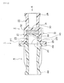
- Fig. 2 is a sectional side view of the device 1.
- the device 1 is constructed such that the first cylindrical member 2 and the second cylindrical member 4 are joined into a single piece by outer flanges 29 and 49 in the aperture periphery.
- the device 1 is constructed from a sterilizable material.
- the first cylindrical member 2 is constructed from a first cylinder part 21 and a second cylinder part 22 continuous to the first cylinder part 21.
- the second cylinder part 22 has a smaller diameter than the first cylinder part 21.
- a first mesh part 31 is formed at the boundary between the first cylinder part 21 and the second cylinder part 22.
- first cylindrical member 2 fibers 32 are pushed in toward the first mesh part 31 and the second mesh part 33 is pushed against the fibers 32. That is, the fibers 32 are pushed and loaded into a space 30 between the first mesh part 31 and the second mesh part 33.
- the first mesh part 31, the fibers 32, and the second mesh part 33 constitute a filter part 10.
- the first mesh part 31 and the second mesh part 33 are disks provided with a large number of through holes.
- the fibers 32 loaded in the space 30 constitute a fiber aggregate filling the space 30. In the fiber aggregate, a large number of small voids are formed between the fibers.
- liquid can move back and forth from the first mesh part 31 to the second mesh part 33 and vice versa passing through the voids in the fiber aggregate.
- the second mesh part 33 is the bottom face of a concave lid 23 fit onto the first cylinder part 21.
- the outer flange 231 in the aperture periphery abuts against the aperture periphery 211 of the first cylinder part 21 so that the second mesh part 33 is positioned in the inside of the first cylinder part 21 at a predetermined distance to the first mesh part 31 and in parallel thereto.
- a luer taper 48 is formed at the aperture end of the second cylindrical member 4.
- a luer taper 28 is formed also at the aperture end of the second cylinder part 22 of the first cylindrical member 2.
- the first cylindrical member 2 and the second cylindrical member 4 are in fluid communication with each other through apertures 20 and 40 of the same size as each other.
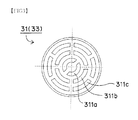
- Fig. 3 is a view of the first mesh part 31 taken in the arrow III direction.
- the first mesh part 31 includes a large number of through holes 311 (i.e., through holes 311a, 311b, and 311c) of arc shape arranged uniformly in a concentric manner. All the through holes 311 have the same area as each other within an error range of 10%.
- the second mesh part 33 also has the same configuration as the first mesh part 31.
- the fibers 32 are of a hydrophobic fiber.
- the hydrophobic fiber polyester, polypropylene, polystyrene, Teflon (registered trademark), nylon, polyvinyl chloride, acrylics, or the like may be employed. However, polyester is preferable. It is preferable that the fibers 32 are crimped.
- the fibers 32 have 50 to 150 deniers and are loaded into the space 30 such that 2.5 to 17.7 mm are present per 1 mm 3 of the space 30.
- loading is performed such that 4.0 to 12. 0 mm are present, and it is more preferable that loading is performed such that 5.0 to 9.9 mm are present.
- the preparation instrument 100 shown in Fig. 1 is used as follows. That is, an emulsion preparation method employing the device 1 is as follows.
- the syringe 8 is charged with a dispersed phase 101 and the syringe 9 is charged with a continuous phase 102.
- a reversed situation may be employed.
- the plunger of one syringe is pushed.
- pumping operation in the direction A is performed on the plunger 82 of the syringe 8.
- the dispersed phase 101 moves through the device 1 to the syringe 9 so that the plunger 92 of the syringe 9 is pushed aside in the direction A.
- the dispersed phase 101 is somewhat mixed with the continuous phase 102.
- both phases 101 and 102 somewhat mixed with each other pass through the filter part 10. That is, both phases 101 and 102 somewhat mixed with each other first pass through the second mesh part 33 so as to be dispersed and mixed at that time, then pass through the fibers 32 so as to be further dispersed and mixed at that time, and then pass through the first mesh part 31 so as to be further dispersed and mixed at that time.
- both phases 101 and 102 having moved to the syringe 8 are in a state of being mixed more than in the syringe 9.
- both phases 101 and 102 mixed more with each other move through the device 1 to the syringe 9 so that the plunger 92 of the syringe 9 is pushed aside in the direction A.
- both phases 101 and 102 mixed more with each other pass through the filter part 10. That is, both phases 101 and 102 mixed more with each other first pass through the first mesh part 31 so as to be dispersed and mixed at that time, then pass through the fibers 32 so as to be further dispersed and mixed at that time, and then pass through the second mesh part 33 so as to be further dispersed and mixed at that time.
- both phases 101 and 102 having moved to the syringe 9 are in a state of being mixed more than in the syringe 8.
- the number of times of the pumping operation is 50 times or smaller. Further, ten times or smaller is more preferable and five times or smaller is the most preferable.
- the state of mixing of both phases 101 and 102 progresses further into a state of emulsion which is a target state.
- the fibers 32 are of a hydrophobic fiber.
- the oil phase serves as a continuous phase and the aqueous phase serves as a dispersed phase so that a water-in-oil type emulsion is formed.
- the fibers 32 have 50 to 150 deniers and are loaded into the space 30 such that 2.5 to 17.7 mm are present per 1 mm 3 of the space 30.
- both phases 101 and 102 can be dispersed and mixed efficiently so that a desired emulsion can be formed.
- the through holes 311 of the same area as each other are arranged uniformly.
- dispersion of both phases 101 and 102 occurs uniformly in the entire region of the mesh part.
- both phases 101 and 102 can be dispersed and mixed efficiently.
- the fibers 32 filling the space 30 have predetermined thickness and length.
- the first mesh part 31 and the second mesh part 33 include a large number of the through holes 311 of arc shape and hence have a large void ratio. Thus, the sliding resistance at the time of pumping operation can be reduced. This improves the operability.
- Fig. 4 is an overall side view of a preparation instrument employing an emulsion preparation device of a second embodiment of the present invention.
- the preparation instrument 100 is constructed from a device 1A and syringes 8 and 9 linked to both sides of the device 1A.
- the syringe 8 is constructed from a cylinder 81 and a plunger 82.
- the syringe 9 is constructed from a cylinder 91 and a plunger 92.
- Fig. 5 is a side view of the device 1A.
- Fig. 6 is a sectional side view of the device 1A.
- the device 1A is different from the device 1 of the first embodiment in the following points.
- the device 1A is constructed such that the first cylindrical member 2 and the second cylindrical member 4 are joined into a single piece by outer flanges 29 and 49 in the aperture periphery.
- the device 1A is constructed from a sterilizable material.
- the first cylindrical member 2 is constructed from a first cylinder part 21 and a second cylinder part 22 continuous to the first cylinder part 21.
- the second cylinder part 22 has a smaller diameter than the first cylinder part 21.
- a first mesh part 31 is formed at the boundary between the first cylinder part 21 and the second cylinder part 22.
- first cylindrical member 2 fibers 32 are pushed in toward the first mesh part 31 and the second mesh part 33 is pushed against the fibers 32. That is, the fibers 32 are loaded into a space 30 between the first mesh part 31 and the second mesh part 33.
- the first mesh part 31, the fibers 32, and the second mesh part 33 constitute a filter part 10.
- the first mesh part 31 and the second mesh part 33 are disks provided with a large number of through holes.
- the fibers 32 filling the space 30 constitute a fiber aggregate filling the space 30. In the fiber aggregate, a large number of small voids are formed between the fibers.
- liquid can move back and forth from the first mesh part 31 to the second mesh part 33 and vice versa passing through the voids in the fiber aggregate.
- the second mesh part 33 is the bottom face of a concave lid 23 fit onto the first cylinder part 21.
- the outer flange 231 in the aperture periphery abuts against the aperture periphery 211 of the first cylinder part 21 so that the second mesh part 33 is positioned in the inside of the first cylinder part 21 at a predetermined distance to the first mesh part 31 and in parallel thereto.
- the first cylindrical member 2 and the second cylindrical member 4 are in fluid communication with each other through apertures 20 and 40 of the same size as each other.
- the aggregate of the fibers 32 filling the space 30 is located in the center of the longitudinal direction. That is, the space 30 is located in the center of the longitudinal direction.
- the external shape of the device 1A is bilaterally symmetric in the longitudinal direction. That is, the first cylindrical member 2 includes an outer flange 29 in the aperture periphery, a large flange 91, a small flange 92, a liquid surface adjustment rib 93, and a connection end part 94.
- the second cylindrical member 4 includes an outer flange 49 in the aperture periphery, a liquid surface adjustment rib 95, and a connection end part 96.
- the large flange 91 is located in the center of the longitudinal direction. Further, on both sides thereof, the small flange 92 and the outer flanges 29 and 49 joined into a single piece are located similarly. Furthermore, on both sides thereof, the liquid surface adjustment rib 93 and the liquid surface adjustment rib 95 are located similarly. Further, on both sides thereof, the connection end part 94 and the connection end part 96 are located similarly. As a result, the device 1A is bilaterally symmetric in the longitudinal direction.
- the first mesh part 31, the fibers 32, and the second mesh part 33 are the same as those in the first embodiment.
- an emulsion can be formed similarly to the first embodiment.
- parts where the formed emulsion remains are spaces 71 and 72, whose volumes are small.
- the generation efficiency for an emulsion can be improved.
- the liquid surface adjustment ribs 93 and 95 indicate the upper limits for the height positions of the continuous phase and the dispersed phase at the time of air vent, and serve as guides used when the plungers 82 and 92 are pushed for air vent.
- the workability of air vent can be improved.
- the device 1 of examples 1 to 14 and the device 1A of example 15 were prepared. Then, emulsion check test A and sliding resistance evaluation test A were performed on the device 1 of examples 1 to 11. Further, emulsion check test B and sliding resistance evaluation test B were performed on the device 1 of examples 12, 13, and 14. Emulsion check test B was performed on the device 1A of example 15. Sliding resistance evaluation test C and foreign substance evaluation test were performed on the device 1 of example 12 and the device 1A of example 15.
- the device 1 having the configuration of Fig. 2 . Detailed dimensions and the like are as follows.
- the fibers 32 are crimped and loaded into the space 30.
- the device 1A having the configuration of Fig. 6 . Detailed dimensions and the like are as follows.
- the fibers 32 are crimped and loaded into the space 30.
- Table 1 shows test results. Each test was performed three times.
- [Table 1] Ex. Fibers Emulsion check test A Thickness (denier) Length (mm) First Second Third 1 50 1000 ⁇ ⁇ ⁇ 2 50 560 ⁇ ⁇ ⁇ 3 50 280 ⁇ ⁇ ⁇ 4 50 140 ⁇ ⁇ ⁇ 5 100 1000 ⁇ ⁇ ⁇ 6 100 560 ⁇ ⁇ ⁇ 7 100 280 ⁇ ⁇ ⁇ 8 100 140 ⁇ ⁇ ⁇ 9 150 560 ⁇ ⁇ ⁇ 10 150 280 ⁇ ⁇ ⁇ 11 150 140 ⁇ ⁇ ⁇
- examples 1 to 11 As seen from Table 1, in examples 1 to 11, a desired emulsion has been formed. In particular, in examples 1, 2, 3, 5, 6, 7, 9, and 10, a satisfactory emulsion has been formed.
- Table 2 shows test results. Each test was performed twice. [Table 2] Ex. Mesh part Emulsion check test B Fiber falling out First Second 12 Fig. 3 ⁇ ⁇ None 13 Fig. 4 ⁇ ⁇ None 14 Fig. 5 ⁇ ⁇ None 15 Fig. 3 ⁇ ⁇ None
- the sliding speed of the plungers 82 and 92 of both syringes 8 and 9 was set at 500 mm/min and 1000 mm/min.
- Table 3 shows test results. Each test was performed once for the sliding speed of the plunger 82 of 500 mm/min and performed twice for 1000 mm/min. [Table 3] Ex. Fibers Sliding speed 500 mm/min Sliding speed 1000 mm/min Thickness (denier) Length (mm) Sliding resistance evaluation test A Sliding resistance evaluation test A First Second 1 50 1000 ⁇ ⁇ ⁇ 2 50 560 ⁇ ⁇ ⁇ 3 50 280 ⁇ ⁇ ⁇ 4 50 140 ⁇ ⁇ ⁇ 5 100 1000 ⁇ ⁇ ⁇ 6 100 560 ⁇ ⁇ ⁇ 7 100 280 ⁇ ⁇ ⁇ 8 100 140 ⁇ ⁇ ⁇ 9 150 560 ⁇ ⁇ ⁇ 10 150 280 ⁇ ⁇ ⁇ 11 150 140 ⁇ ⁇ ⁇ ⁇
- Table 4 shows test results. [Table 4] Ex. Mesh part Sliding resistance (N) First pumping Second pumping Third pumping Average Standard Deviation Syr. 8 Syr. 9 Syr. 8 Syr. 9 Syr. 8 Syr. 9 12 Fig. 3 20.23 19.51 18.50 20.07 20.79 21.17 20.05 0.95 13 Fig. 4 21.71 23.01 23.89 25.75 23.59 1.70 14 Fig. 5 33.08 30.39 26.91 27.37 29.44 2.88
- Table 5 shows test results. [Table 5] Ex. Mesh part Sliding resistance (N) First pumping Second pumping Third pumping Average Standard Deviation Syr. 8 Syr. 9 Syr. 8 Syr. 9 Syr. 8 Syr. 9 12 Fig. 3 23.32 22.57 21.25 34.50 21.20 21.63 24.08 4.72 15 Fig. 3 22.69 27.98 25.38 25.70 22.48 22.93 24.53 2.01
- Table 6 shows the results of example 12.
- Table 7 shows the results of example 15. [Table 6] Partic. Size ( ⁇ m) First Second Third Fourth Fifth Average 1.3 ⁇ 88 137 73 64 71 87 2 ⁇ 45 74 37 35 36 45 5 ⁇ 24 27 16 14 12 19 10 ⁇ 15 14 11 4 5 10 15 ⁇ 5 4 4 1 2 3 25 ⁇ 0 0 0 0 0 50 ⁇ 0 0 0 0 0 0 100 ⁇ 0 0 0 0 0 0 0 [Table 7] Partic.
- the allowance criterion for the average number of particulates is "6000 or fewer for particulates of 10 ⁇ m or larger and 600 or fewer for particulates of 25 ⁇ m or larger, per vessel".
- a ten-fold severer allowance criterion was employed that "600 or fewer for particulates of 10 ⁇ m or larger and 60 or fewer for particulates of 25 ⁇ m or larger, per vessel”.
- both devices 1 and 1A are excellent in the foreign substance quality and hence have sufficient cleanliness for the use as medical equipment.
- the emulsion preparation device of the present invention can form an emulsion for a chemical liquid of diverse composition, further can realize a relatively low sliding resistance, and hence has a great advantage in industrial utilization.
Landscapes
- Chemical & Material Sciences (AREA)
- Chemical Kinetics & Catalysis (AREA)
- Dispersion Chemistry (AREA)
- Life Sciences & Earth Sciences (AREA)
- Engineering & Computer Science (AREA)
- Wood Science & Technology (AREA)
- Infusion, Injection, And Reservoir Apparatuses (AREA)
- Accessories For Mixers (AREA)
- Colloid Chemistry (AREA)
Abstract
Description
- The present invention relates to a device and a preparation method for mixing a continuous phase and a dispersed phase with each other so as to form an emulsion.
- As emulsion preparation devices in the field of medical equipment, chemical liquid preparation connectors described in
Patent Documents - Nevertheless, in the connector of
Patent Document 1, according to investigation by the present inventors, it has been recognized that: a large amount of pumping operation is necessary for forming a sufficient emulsion; further, depending on the composition of the chemical liquid, a sufficient emulsion cannot be formed in some cases; and further, an inconvenience of relatively high sliding resistance is present at the time of pumping operation. Further, the connector ofPatent Document 1 does not include a filter part. A filter part in the connector ofPatent Document 2 employs a porous material fabricated from a glass membrane. None of the connectors of both documents includes a filter part filled with fibers. Patent Document 3 relates to a filter filled with fibers but does not describe an emulsion preparation device. Further,Patent Document 4 also does not describe a connector provided with a filter part filled with fibers. -
- Patent Document 1: International Publication No.
2007/083763 - Patent Document 2: Japanese Unexamined Patent Application Publication No.
2005-186026 - Patent Document 3: Japanese Examined Patent Application Publication No.
S52-35235 - Patent Document 4: Japanese Unexamined Patent Application Publication No.
2006-346565 - An object of the present invention is to provide an emulsion preparation device and an emulsion preparation method capable of forming an emulsion in a chemical liquid of diverse composition and further realizing a relatively low sliding resistance.
- The present invention is characterized by an emulsion preparation device provided with a filter part, wherein: the filter part is constructed from a first and a second mesh part and fibers; and the fibers are loaded into a space between the first mesh part and the second mesh part. That is, the present invention provides the following (1) to (12).
-
- (1) An emulsion preparation device provided with a filter part, wherein:
- the filter part is constructed from a first and a second mesh part and fibers;
- and the fibers are loaded into a space between the first mesh part and the second mesh part.
- (2) The emulsion preparation device according to the above-mentioned (1), wherein:
- one side or both sides of the filter part can be connected to a syringe; and
- an emulsion is formed when a continuous phase and a dispersed phase perform, through the filter part, reciprocating movement between two syringes linked to the both sides of the filter part or alternatively between a syringe linked to one side and a vessel linked to the other side.
- (3) The emulsion preparation device according to the above-mentioned (1) or (2), wherein
the first mesh part and/or the second mesh part are disks. - (4) The emulsion preparation device according to the above-mentioned (3), wherein
the mesh part includes a large number of through holes of arc shape arranged uniformly in a concentric manner and all the through holes have the same area as each other within an error range of 10%. - (5) The emulsion preparation device according to any one of the above-mentioned (1) to (4), wherein
the fibers are of a hydrophobic fiber. - (6) The emulsion preparation device according to the above-mentioned (5), wherein
the hydrophobic fiber is polyester. - (7) The emulsion preparation device according to any one of the above-mentioned (1) to (4), wherein
the fibers are of a hydrophilic fiber. - (8) The emulsion preparation device according to any one of the above-mentioned (1) to (7), wherein
the fibers have 50 to 150 deniers and are loaded such that 2.5 to 17.7 mm are present per 1 mm3 of the space. - (9) The emulsion preparation device according to any one of the above-mentioned (1) to (8), wherein
the fibers have 50 to 150 deniers and are loaded such that 5.0 to 9.9 mm are present per 1 mm3 of the space. - (10) The emulsion preparation device according to any one of the above-mentioned (1) to (9), constructed from
a first cylindrical member and a second cylindrical member, wherein:- the first cylindrical member is constructed from a first cylinder part and a second cylinder part continuous to the first cylinder part;
- the second cylinder part has a smaller diameter than the first cylinder part;
- in the first cylindrical member, the first mesh part is formed at a boundary between the first cylinder part and the second cylinder part, the fibers are pushed in toward the first mesh part, the second mesh part is pushed against the fibers, and, as a result, the filter part constructed from the first mesh part, the fiber aggregate, and the second mesh part is formed;
- the second mesh part is a bottom face of a concave lid fit onto the first cylinder part;
- in the concave lid, an outer flange in an aperture periphery abuts against an aperture periphery of the first cylinder part so that the second mesh part is positioned in the inside of the first cylinder part at a predetermined distance to the first mesh part and in parallel thereto; and
- the first cylindrical member and the second cylindrical member are joined into a single piece by the outer flange in the aperture periphery of the first cylinder part and an outer flange in an aperture periphery of the second cylindrical member.
- (11) The emulsion preparation device according to any one of the above-mentioned (1) to (9), constructed from
a first cylindrical member and a second cylindrical member, wherein:- the first cylindrical member is constructed from a first cylinder part and a second cylinder part continuous to the first cylinder part;
- the second cylinder part has a smaller diameter than the first cylinder part;
- in the first cylindrical member, the first mesh part is formed at a boundary between the first cylinder part and the second cylinder part, the fibers are pushed in toward the first mesh part, the second mesh part is pushed against the fibers, and, as a result, the filter part constructed from the first mesh part, the fiber aggregate, and the second mesh part is formed;
- the second mesh part is a bottom face of a concave lid fit onto the first cylinder part;
- in the concave lid, an outer flange in an aperture periphery abuts against an aperture periphery of the first cylinder part so that the second mesh part is positioned in the inside of the first cylinder part at a predetermined distance to the first mesh part and in parallel thereto;
- the first cylindrical member and the second cylindrical member are joined into a single piece by the outer flange in the aperture periphery of the first cylinder part and an outer flange in an aperture periphery of the second cylindrical member;
- the fiber aggregate is located in a center of a longitudinal direction; and
- in a state that the first cylindrical member and the second cylindrical member have been joined into a single piece, an external shape is bilaterally symmetric in the longitudinal direction.
- (12) An emulsion preparation method employing the emulsion preparation device according to any one of the above-mentioned (1) to (11).
- The emulsion preparation method according to the present invention is characterized by employing the above-mentioned emulsion preparation device according to the present invention.
- According to the present invention, in a chemical liquid of diverse composition, an emulsion can be formed and further the sliding resistance can be made relatively low.
-
-
Fig. 1 is an overall side view of a preparation instrument employing an emulsion preparation device of a first embodiment of the present invention. -
Fig. 2 is a sectional side view of a device ofFig. 1 . -
Fig. 3 is a view taken in an arrow III direction inFig. 1 and showing a first mesh part. -
Fig. 4 is an overall side view of a preparation instrument employing an emulsion preparation device of a second embodiment of the present invention. -
Fig. 5 is a side view of a device ofFig. 4 . -
Fig. 6 is a sectional side view of a device ofFig. 4 . -
Fig. 7 is a transparent side view of a device ofFig. 4 . -
Fig. 8 is a diagram showing a modification of a first mesh part. -
Fig. 9 is a diagram showing another modification of a first mesh part. -
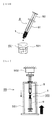
Fig. 10 is a diagram showing a drop test in emulsion check tests A and B. -
Fig. 11 is a diagram showing a step in a method of sliding resistance evaluation tests A and B. -
Fig. 12 is a diagram showing a step in a method of foreign substance evaluation test. -
Fig. 1 is an overall side view of a preparation instrument employing an emulsion preparation device of a first embodiment of the present invention. Thepreparation instrument 100 is constructed from adevice 1 andsyringes device 1. Thesyringe 8 is constructed from acylinder 81 and aplunger 82. Thesyringe 9 is constructed from acylinder 91 and aplunger 92. -
Fig. 2 is a sectional side view of thedevice 1. Thedevice 1 is constructed such that the firstcylindrical member 2 and the secondcylindrical member 4 are joined into a single piece byouter flanges device 1 is constructed from a sterilizable material. - The first
cylindrical member 2 is constructed from afirst cylinder part 21 and asecond cylinder part 22 continuous to thefirst cylinder part 21. Thesecond cylinder part 22 has a smaller diameter than thefirst cylinder part 21. In the firstcylindrical member 2, afirst mesh part 31 is formed at the boundary between thefirst cylinder part 21 and thesecond cylinder part 22. - Then, in the first
cylindrical member 2,fibers 32 are pushed in toward thefirst mesh part 31 and thesecond mesh part 33 is pushed against thefibers 32. That is, thefibers 32 are pushed and loaded into aspace 30 between thefirst mesh part 31 and thesecond mesh part 33. Thefirst mesh part 31, thefibers 32, and thesecond mesh part 33 constitute afilter part 10. Here, thefirst mesh part 31 and thesecond mesh part 33 are disks provided with a large number of through holes. Thefibers 32 loaded in thespace 30 constitute a fiber aggregate filling thespace 30. In the fiber aggregate, a large number of small voids are formed between the fibers. Thus, in thefilter part 10, liquid can move back and forth from thefirst mesh part 31 to thesecond mesh part 33 and vice versa passing through the voids in the fiber aggregate. - The
second mesh part 33 is the bottom face of aconcave lid 23 fit onto thefirst cylinder part 21. In theconcave lid 23, theouter flange 231 in the aperture periphery abuts against theaperture periphery 211 of thefirst cylinder part 21 so that thesecond mesh part 33 is positioned in the inside of thefirst cylinder part 21 at a predetermined distance to thefirst mesh part 31 and in parallel thereto. - A
luer taper 48 is formed at the aperture end of the secondcylindrical member 4. Aluer taper 28 is formed also at the aperture end of thesecond cylinder part 22 of the firstcylindrical member 2. The firstcylindrical member 2 and the secondcylindrical member 4 are in fluid communication with each other throughapertures -
Fig. 3 is a view of thefirst mesh part 31 taken in the arrow III direction. Thefirst mesh part 31 includes a large number of through holes 311 (i.e., throughholes second mesh part 33 also has the same configuration as thefirst mesh part 31. - The
fibers 32 are of a hydrophobic fiber. As the hydrophobic fiber, polyester, polypropylene, polystyrene, Teflon (registered trademark), nylon, polyvinyl chloride, acrylics, or the like may be employed. However, polyester is preferable. It is preferable that thefibers 32 are crimped. Thefibers 32 have 50 to 150 deniers and are loaded into thespace 30 such that 2.5 to 17.7 mm are present per 1 mm3 of thespace 30. Here, it is preferable that loading is performed such that 4.0 to 12. 0 mm are present, and it is more preferable that loading is performed such that 5.0 to 9.9 mm are present. - The
preparation instrument 100 shown inFig. 1 is used as follows. That is, an emulsion preparation method employing thedevice 1 is as follows. Here, in thepreparation instrument 100, thesyringe 8 is charged with a dispersedphase 101 and thesyringe 9 is charged with acontinuous phase 102. However, a reversed situation may be employed. - First, the plunger of one syringe is pushed. For example, pumping operation in the direction A is performed on the
plunger 82 of thesyringe 8. By virtue of this, the dispersedphase 101 moves through thedevice 1 to thesyringe 9 so that theplunger 92 of thesyringe 9 is pushed aside in the direction A. At that time, in thesyringe 9, the dispersedphase 101 is somewhat mixed with thecontinuous phase 102. - Next, pumping operation in the direction B is performed on the
plunger 92 of thesyringe 9. By virtue of this, the dispersedphase 101 and thecontinuous phase 102 somewhat mixed with each other move through thedevice 1 to thesyringe 8 so that theplunger 82 of thesyringe 8 is pushed aside in the direction B. At that time, in thedevice 1, bothphases filter part 10. That is, bothphases second mesh part 33 so as to be dispersed and mixed at that time, then pass through thefibers 32 so as to be further dispersed and mixed at that time, and then pass through thefirst mesh part 31 so as to be further dispersed and mixed at that time. Thus, bothphases syringe 8 are in a state of being mixed more than in thesyringe 9. - Next, pumping operation in the direction A is performed on the
plunger 82 of thesyringe 8. By virtue of this, bothphases device 1 to thesyringe 9 so that theplunger 92 of thesyringe 9 is pushed aside in the direction A. At that time, in thedevice 1, bothphases filter part 10. That is, bothphases first mesh part 31 so as to be dispersed and mixed at that time, then pass through thefibers 32 so as to be further dispersed and mixed at that time, and then pass through thesecond mesh part 33 so as to be further dispersed and mixed at that time. Thus, bothphases syringe 9 are in a state of being mixed more than in thesyringe 8. - As such, pumping operation on the
plunger 82 of thesyringe 8 and pumping operation on theplunger 92 of thesyringe 9 are repeated alternately. It is preferable that the number of times of the pumping operation is 50 times or smaller. Further, ten times or smaller is more preferable and five times or smaller is the most preferable. By virtue of this, the state of mixing of bothphases fibers 32 are of a hydrophobic fiber. Thus, the oil phase serves as a continuous phase and the aqueous phase serves as a dispersed phase so that a water-in-oil type emulsion is formed. - According to the
device 1 of the configuration, thefibers 32 have 50 to 150 deniers and are loaded into thespace 30 such that 2.5 to 17.7 mm are present per 1 mm3 of thespace 30. Thus, bothphases - Further, in the
first mesh part 31 and thesecond mesh part 33, the through holes 311 of the same area as each other are arranged uniformly. Thus, dispersion of bothphases phases - Further, the
fibers 32 filling thespace 30 have predetermined thickness and length. Further, thefirst mesh part 31 and thesecond mesh part 33 include a large number of the through holes 311 of arc shape and hence have a large void ratio. Thus, the sliding resistance at the time of pumping operation can be reduced. This improves the operability. -
Fig. 4 is an overall side view of a preparation instrument employing an emulsion preparation device of a second embodiment of the present invention. Thepreparation instrument 100 is constructed from adevice 1A andsyringes device 1A. Thesyringe 8 is constructed from acylinder 81 and aplunger 82. Thesyringe 9 is constructed from acylinder 91 and aplunger 92. -
Fig. 5 is a side view of thedevice 1A.Fig. 6 is a sectional side view of thedevice 1A. Thedevice 1A is different from thedevice 1 of the first embodiment in the following points. - (i) The aggregate of the
fibers 32 filling thespace 30 is located in the center of the longitudinal direction. - (ii) The external shape is bilaterally symmetric in the longitudinal direction.
- (iii) Liquid
surface adjustment ribs - That is, the difference is as follows.
- The
device 1A is constructed such that the firstcylindrical member 2 and the secondcylindrical member 4 are joined into a single piece byouter flanges device 1A is constructed from a sterilizable material. - The first
cylindrical member 2 is constructed from afirst cylinder part 21 and asecond cylinder part 22 continuous to thefirst cylinder part 21. Thesecond cylinder part 22 has a smaller diameter than thefirst cylinder part 21. In the firstcylindrical member 2, afirst mesh part 31 is formed at the boundary between thefirst cylinder part 21 and thesecond cylinder part 22. - Then, in the first
cylindrical member 2,fibers 32 are pushed in toward thefirst mesh part 31 and thesecond mesh part 33 is pushed against thefibers 32. That is, thefibers 32 are loaded into aspace 30 between thefirst mesh part 31 and thesecond mesh part 33. Thefirst mesh part 31, thefibers 32, and thesecond mesh part 33 constitute afilter part 10. Here, thefirst mesh part 31 and thesecond mesh part 33 are disks provided with a large number of through holes. Thefibers 32 filling thespace 30 constitute a fiber aggregate filling thespace 30. In the fiber aggregate, a large number of small voids are formed between the fibers. Thus, in thefilter part 10, liquid can move back and forth from thefirst mesh part 31 to thesecond mesh part 33 and vice versa passing through the voids in the fiber aggregate. - The
second mesh part 33 is the bottom face of aconcave lid 23 fit onto thefirst cylinder part 21. In theconcave lid 23, theouter flange 231 in the aperture periphery abuts against theaperture periphery 211 of thefirst cylinder part 21 so that thesecond mesh part 33 is positioned in the inside of thefirst cylinder part 21 at a predetermined distance to thefirst mesh part 31 and in parallel thereto. - The first
cylindrical member 2 and the secondcylindrical member 4 are in fluid communication with each other throughapertures - Then, the aggregate of the
fibers 32 filling thespace 30 is located in the center of the longitudinal direction. That is, thespace 30 is located in the center of the longitudinal direction. - Further, as seen from
Fig. 5 , the external shape of thedevice 1A is bilaterally symmetric in the longitudinal direction. That is, the firstcylindrical member 2 includes anouter flange 29 in the aperture periphery, alarge flange 91, asmall flange 92, a liquidsurface adjustment rib 93, and aconnection end part 94. On the other hand, the secondcylindrical member 4 includes anouter flange 49 in the aperture periphery, a liquidsurface adjustment rib 95, and aconnection end part 96. Then, when the firstcylindrical member 2 and the secondcylindrical member 4 abut against each other at theouter flange 29 and theouter flange 49 so as to be joined together, in thedevice 1A, thelarge flange 91 is located in the center of the longitudinal direction. Further, on both sides thereof, thesmall flange 92 and theouter flanges surface adjustment rib 93 and the liquidsurface adjustment rib 95 are located similarly. Further, on both sides thereof, theconnection end part 94 and theconnection end part 96 are located similarly. As a result, thedevice 1A is bilaterally symmetric in the longitudinal direction. - The
first mesh part 31, thefibers 32, and thesecond mesh part 33 are the same as those in the first embodiment. - When the
preparation instrument 100 shown inFig. 4 is used similarly to the first embodiment, an emulsion can be formed similarly to the first embodiment. - Further, in the
device 1A, as shown inFig. 7 , parts where the formed emulsion remains arespaces device 1A, the generation efficiency for an emulsion can be improved. - Further, in the
device 1A, the liquidsurface adjustment ribs plungers device 1A, the workability of air vent can be improved. - The following modified structures may be adopted.
- (1) The
fibers 32 may be of a hydrophilic fiber. For example, cotton, rayon, vinylon, or the like may be employed. In this case, the aqueous phase serves as a continuous phase and the oil phase serves as a dispersed phase so that an oil-in-water type emulsion is formed. - (2) The
first mesh part 31 and thesecond mesh part 33 may be disks as shown inFig. 8 or 9 . The mesh part inFig. 8 includes a large number of through holes 312 (i.e., throughholes Fig. 9 includes a large number ofcircular holes 313 distributed uniformity. Then, all thecircular holes 313 have the same area as each other. - (3) The
first mesh part 31 and thesecond mesh part 33 may have a shape other than the disk and, for example, may have the shape of a block. - (4) A mixed solution of a dispersed phase and a continuous phase may be loaded in any one of the
syringe 8 and thesyringe 9. In this case, no liquid is loaded in the other one. - The
device 1 of examples 1 to 14 and thedevice 1A of example 15 were prepared. Then, emulsion check test A and sliding resistance evaluation test A were performed on thedevice 1 of examples 1 to 11. Further, emulsion check test B and sliding resistance evaluation test B were performed on thedevice 1 of examples 12, 13, and 14. Emulsion check test B was performed on thedevice 1A of example 15. Sliding resistance evaluation test C and foreign substance evaluation test were performed on thedevice 1 of example 12 and thedevice 1A of example 15. - The
device 1 having the configuration ofFig. 2 . Detailed dimensions and the like are as follows. Here, thefibers 32 are crimped and loaded into thespace 30. - ·Space 30:
- ·56.52 mm3
- -Fibers 32:
- -Polyester
- ·50 deniers
- ·1000 mm (17.7 mm is present per 1 mm3 of space 30)
- ·
First mesh part 31 and second mesh part 33:- -Configuration of
Fig. 3 - ·Through
hole 311a: 0.43 mm2 - ·Through
hole 311b: 0.45 mm2 - ·Through
hole 311c: 0.46 mm2 - -Opening area: 5.42 mm2
- ·Through
- -Configuration of
- The following point alone is different from example 1.
- -Fibers 32:
- ·560 mm (9.9 mm is present per 1 mm3 of space 30)
- The following point alone is different from example 1.
- Fibers 32:
- ·280 mm (5.0 mm is present per 1 mm3 of space 30)
- The following point alone is different from example 1.
- -Fibers 32:
- ·140 mm (2.5 mm is present per 1 mm3 of space 30)
- The following point alone is different from example 1.
- ·Fibers 32:
- ·100 deniers
- The following points alone are different from example 1.
- ·Fibers 32:
- ·100 deniers
- ·560 mm (9.9 mm is present per 1 mm3 of space 30)
- The following points alone are different from example 1.
- ·Fibers 32:
- ·100 deniers
- ·280 mm (5.0 mm is present per 1 mm3 of space 30)
- The following points alone are different from example 1.
- ·Fibers 32:
- ·100 deniers
- ·140 mm (2.5 mm is present per 1 mm3 of space 30)
- The following points alone are different from example 1.
- ·Fibers 32:
- ·150 deniers
- ·560 mm (9.9 mm is present per 1 mm3 of space 30)
- The following points alone are different from example 1.
- ·Fibers 32:
- ·150 deniers
- ·280 mm (5.0 mm is present per 1 mm3 of space 30)
- The following points alone are different from example 1.
- ·Fibers 32:
- ·150 deniers
- ·140 mm (2.5 mm is present per 1 mm3 of space 30)
- The following points alone are different from example 1.
- ·Fibers 32:
- ·75 deniers
- ·280 mm (5.0 mm is present per 1 mm3 of space 30)
- The following points alone are different from example 12.
- ·
First mesh part 31 and second mesh part 33:- ·Configuration of
Fig. 4 - ·Through
hole 312a: 0.17 mm2 - ·Through
hole 312b: 0.18 mm2 - ·Through
hole 312c: 0.35 mm2 - ·Opening area: 4.92 mm2
- ·Through
- ·Configuration of
- The following points alone are different from example 12.
- ·
First mesh part 31 and second mesh part 33:- ·Configuration of
Fig. 5 - ·Through hole 313: 0.07 mm2
- ·Opening area: 2.45 mm2
- ·Configuration of
- The
device 1A having the configuration ofFig. 6 . Detailed dimensions and the like are as follows. Here, thefibers 32 are crimped and loaded into thespace 30. - ·Space 30:
- ·56.52 mm3
- ·Fibers 32:
- ·Polyester
- ·75 deniers
- ·280 mm (5.0 mm is present per 1 mm3 of space 30)
- ·
First mesh part 31 and second mesh part 33:- ·Configuration of
Fig. 3 - ·Through
hole 311a: 0.43 mm2 - ·Through
hole 311b: 0.45 mm2 - ·Through
hole 311c: 0.46 mm2 - ·Opening area: 5.42 mm2
- ·Through
- ·Configuration of
- As shown in
Figs. 1 and10 , the following procedure was employed. - (1) The
preparation instrument 100 ofFig. 1 was prepared. Then, 1.5 ml of 2% L-arginine aqueous solution serving as a dispersed phase, that is, an aqueous phase, was loaded into thespace 8. Then, 1.5 ml of Montanide (official name: Montanide ISA 51VG) serving as a continuous phase, that is, an oil phase, was loaded into thesyringe 9. Here, thesyringes - (2) Pumping operation was manually performed alternately on the
plunger 82 of thesyringe 8 and theplunger 92 of thesyringe 9. This operation was repeated 5 times. As a result, both phases were accommodated into thesyringe 8. - (3) The
syringe 9 was removed. Then, as shown inFig. 10 , a mixed solution of physiological saline solution and Montanide in thecylinder 8 was dripped through thedevice 1 to thesurface 521 of the water in thevessel 52. That is, a so-called "droop test" was performed. - Table 1 shows test results. Each test was performed three times.
[Table 1] Ex. Fibers Emulsion check test A Thickness (denier) Length (mm) First Second Third 1 50 1000 ○ ○ ○ 2 50 560 ○ ○ ○ 3 50 280 ○ ○ ○ 4 50 140 × ○ × 5 100 1000 ○ ○ ○ 6 100 560 ○ ○ ○ 7 100 280 ○ ○ ○ 8 100 140 ○ ○ × 9 150 560 ○ ○ ○ 10 150 280 ○ ○ ○ 11 150 140 × ○ × - When dripped liquid does not diffuse over the
surface 521, an emulsion has been formed satisfactorily. This situation is indicated by "o" in the test result. When dripped liquid diffuses over thesurface 521, an emulsion has not been formed. This situation is indicated by "×" in the test result. - As seen from Table 1, in examples 1 to 11, a desired emulsion has been formed. In particular, in examples 1, 2, 3, 5, 6, 7, 9, and 10, a satisfactory emulsion has been formed.
- As shown in
Figs. 1 and10 , the following procedure was employed. - (1) The
preparation instrument 100 ofFig. 1 was prepared in examples 12 to 14 and thepreparation instrument 100 ofFig. 4 was prepared in example 15. Then, 1.5 ml of 2% L-arginine aqueous solution serving as a dispersed phase, that is, an aqueous phase, was loaded into thespace 8. Then, 1.5 ml of Montanide serving as a continuous phase, that is, an oil phase, was loaded into thespace 9. Here, thesyringes - (2) Pumping operation of alternately pushing on the
plunger 82 of thesyringe 8 and theplunger 92 of thesyringe 9 was performed manually. This operation was repeated 5 times. As a result, both phases were accommodated into thesyringe 8. - (3) The
syringe 9 was removed. Then, as shown inFig. 10 , a mixed solution of L-arginine aqueous solution and Montanide in thecylinder 8 was dripped through thedevice 1 to thesurface 521 of the water in thevessel 52. That is, a so-called "drop test" was performed. Further, at that time, the presence or absence of falling out of thefibers 32 in thedevice 1 was also investigated. - Table 2 shows test results. Each test was performed twice.
[Table 2] Ex. Mesh part Emulsion check test B Fiber falling out First Second 12 Fig. 3 ○ ○ None 13 Fig. 4 ○ ○ None 14 Fig. 5 ○ ○ None 15 Fig. 3 ○ ○ None - The meanings of "○" and "×" in the test results are the same as in emulsion check test A.
- As seen from Table 2, even when the
first mesh part 31 and thesecond mesh part 33 had whichever configuration ofFigs. 3 ,8, and 9 , a satisfactory emulsion has been formed. - As shown in
Fig. 11 , the following procedure was employed. - (1) The
preparation instrument 100 ofFig. 1 was prepared. Then, 1.5 ml of 2% L-arginine aqueous solution serving as a dispersed phase, that is, an aqueous phase, was loaded into thespace 8. Then, 1.5 ml of Montanide serving as a continuous phase, that is, an oil phase, was loaded into thespace 9. Here, thesyringes - (2) Pumping operation was manually performed alternately on the
plunger 82 of thesyringe 8 and theplunger 92 of thesyringe 9. This operation was repeated 5 times. As a result, both phases were accommodated into thesyringe 8. - (3) As shown in
Fig. 11 , thepreparation instrument 100 was installed in an autograph device 55 (model EZ-L-500N, Shimadzu Corporation) provided with asupport base 551 and aload cell 552. Then, the sliding resistance at the time of alternately pushing theplunger 82 of thesyringe 8 and theplunger 92 of thesyringe 9 was measured with theload cell 552. Further, as the resistance, a mean value was calculated for the load during the plunger stroke from 5 to 15 mm. - Here, the sliding speed of the
plungers syringes - Table 3 shows test results. Each test was performed once for the sliding speed of the
plunger 82 of 500 mm/min and performed twice for 1000 mm/min.[Table 3] Ex. Fibers Sliding speed 500 mm/min Sliding speed 1000 mm/min Thickness (denier) Length (mm) Sliding resistance evaluation test A Sliding resistance evaluation test A First Second 1 50 1000 ○ ○ × 2 50 560 ○ ○ ○ 3 50 280 ○ ○ ○ 4 50 140 ○ ○ ○ 5 100 1000 × ○ × 6 100 560 ○ ○ ○ 7 100 280 ○ ○ ○ 8 100 140 ○ ○ ○ 9 150 560 ○ ○ ○ 10 150 280 ○ ○ ○ 11 150 140 ○ ○ ○ - In a case that the pumping operation speed is 500 mm/min, the operability is light and satisfactory when the sliding resistance is lower than 70 N. Thus, this situation is indicated by "○". Further, in case of 70 N or higher, this situation is indicated by "×". Further, in a case that the pumping operation speed is 1000 mm/min, the operability is light and satisfactory when the sliding resistance is lower than 140 N. Thus, this situation is indicated by "○". Further, in case of 140 N or higher, this situation is indicated by "×".
- As seen from Table 3, in examples 1 to 11, the operability of pumping was satisfactory.
- As shown in
Fig. 11 , the following procedure was employed. - (1) The
preparation instrument 100 ofFig. 1 was prepared. Then, 1.5 ml of 2% L-arginine aqueous solution serving as a dispersed phase, that is, an aqueous phase, was loaded into thespace 8. Then, 1.5 ml of Montanide serving as a continuous phase, that is, an oil phase, was loaded into thespace 9. Here, thesyringes - (2) Pumping operation was manually performed alternately on the
plunger 82 of thesyringe 8 and theplunger 92 of thesyringe 9. This operation was repeated 5 times. As a result, both phases were accommodated into thesyringe 8. - (3) As shown in
Fig. 11 , thepreparation instrument 100 was installed in an autograph device 55 (model AG-500BR, Shimadzu Corporation) provided with asupport base 551 and aload cell 552. Then, the sliding resistance at the time of alternately pushing theplunger 82 of thesyringe 8 and theplunger 92 of thesyringe 9 was measured with theload cell 552. The resistance was measured at the first time, the second time, and the third time of pumping operation. Further, as the resistance, a mean value was calculated for the load during the plunger stroke from 5 to 15 mm. The sliding speed was set at 500 mm/min. - Table 4 shows test results.
[Table 4] Ex. Mesh part Sliding resistance (N) First pumping Second pumping Third pumping Average Standard Deviation Syr. 8 Syr. 9 Syr. 8 Syr. 9 Syr. 8 Syr. 9 12 Fig. 3 20.23 19.51 18.50 20.07 20.79 21.17 20.05 0.95 13 Fig. 4 21.71 23.01 23.89 25.75 23.59 1.70 14 Fig. 5 33.08 30.39 26.91 27.37 29.44 2.88 - As seen from Table 4, in examples 12, 13, and 14, the sliding resistance was lower than the conventional art. Thus, the operability was satisfactory. In particular, in example 12, that is, in a case that the mesh part having the configuration of
Fig. 3 was employed, the sliding resistance was the lowest. Thus, in a case that the mesh part having the configuration ofFig. 3 was employed, the operability was the most satisfactory. - As shown in
Fig. 11 , the following procedure was employed. - (1) The
preparation instrument 100 ofFig. 1 was prepared in example 12 and thepreparation instrument 100 ofFig. 4 was prepared in example 15. Then, 1.5 ml of physiological saline serving as a dispersed phase, that is, an aqueous phase, was loaded into thesyringe 8. Then, 1.5 ml of Montanide serving as a continuous phase, that is, an oil phase, was loaded into thespace 9. Here, thesyringes - (2) Pumping operation was manually performed alternately on the
plunger 82 of thesyringe 8 and theplunger 92 of thesyringe 9. This operation was repeated 5 times. As a result, both phases were accommodated into thesyringe 8. - (3) As shown in
Fig. 11 , thepreparation instrument 100 was installed in an autograph device 55 (model AG-Xplus, Shimadzu Corporation) provided with asupport base 551 and aload cell 552. Then, the sliding resistance at the time of alternately pushing theplunger 82 of thesyringe 8 and theplunger 92 of thesyringe 9 was measured with theload cell 552. The resistance was measured at the first time, the second time, and the third time of pumping operation. Further, as the resistance, a mean value was calculated for the load during the plunger stroke from 5 to 15 mm. The sliding speed was set at 500 mm/min. - Table 5 shows test results.
[Table 5] Ex. Mesh part Sliding resistance (N) First pumping Second pumping Third pumping Average Standard Deviation Syr. 8 Syr. 9 Syr. 8 Syr. 9 Syr. 8 Syr. 9 12 Fig. 3 23.32 22.57 21.25 34.50 21.20 21.63 24.08 4.72 15 Fig. 3 22.69 27.98 25.38 25.70 22.48 22.93 24.53 2.01 - As seen from Table 5, in examples 12 and 15, the sliding resistance was lower than the conventional art. Thus, the operability was satisfactory.
-
- (1)
Fig. 12 shows the situation of the test concerning thedevice 1 of example 12. Here, in example 15, thedevice 1A was employed in place of thedevice 1. Aglass syringe 62 was attached through a 0.8-µm membrane filter 61 to one end of thedevice 1. Then, 10 ml of particulate-free deionized water was vigorously ejected through thefilter 61 and thedevice 1 into aclean glass bottle 63. This operation was performed five times in total. Then, thefilter 61 and thesyringe 62 were removed and then attached to the other end of thedevice 1 similarly, and then the same operation was performed. By virtue of this, approximately 100 ml of deionized water was collected in theglass bottle 63. This deionized water was employed as the sample. - (2) Japanese Pharmacopoeia Sixteenth Edition "Insoluble Particulate Matter Test for Injections,
Method 1. Light Obscuration Particle Count Test" was performed on the sample. Specifically, insoluble particulates per 10 ml of the sample were measured four times with an in-liquid particulate measurement instrument (product name: RION KL-04). Then, the second to the fourth measurement values were converted into the number of particulates per vessel. This measurement was performed five times in total with changing the sample. - Table 6 shows the results of example 12. Table 7 shows the results of example 15.
[Table 6] Partic. Size (µm) First Second Third Fourth Fifth Average 1.3≤ 88 137 73 64 71 87 2≤ 45 74 37 35 36 45 5≤ 24 27 16 14 12 19 10≤ 15 14 11 4 5 10 15≤ 5 4 4 1 2 3 25≤ 0 0 0 0 0 0 50≤ 0 0 0 0 0 0 100≤ 0 0 0 0 0 0 [Table 7] Partic. Size (µm) First Second Third Fourth Fifth Average 1.3≤ 980 108 155 210 108 136 2≤ 500 47 85 74 65 64 5≤ 200 15 39 23 21 24 10≤ 80 8 18 6 2 8 15≤ 30 4 3 1 0 2 25≤ 0 0 0 0 0 50≤ 0 0 0 0 0 0 100≤ 0 0 0 0 0 0 - With reference to a test method "B. Solutions for injection supplied in containers with a nominal content of less than 100 ml" in the above-mentioned Japanese Pharmacopoeia, the allowance criterion for the average number of particulates is "6000 or fewer for particulates of 10 µm or larger and 600 or fewer for particulates of 25 µm or larger, per vessel". However, in the present test, a ten-fold severer allowance criterion was employed that "600 or fewer for particulates of 10 µm or larger and 60 or fewer for particulates of 25 µm or larger, per vessel".
- In both of examples 12 and 15, the severer allowance criterion has been satisfied. Thus, both
devices - The emulsion preparation device of the present invention can form an emulsion for a chemical liquid of diverse composition, further can realize a relatively low sliding resistance, and hence has a great advantage in industrial utilization.
- 1: 1A Device, 10: Filter part, 100: Preparation instrument, 2: First cylindrical member, 21: First cylinder part, 211: Aperture periphery, 22: Second cylinder part, 23: Concave lid, 231: Outer flange, 28: Luer taper, 31: First mesh part, 311: Through hole, 32: Fibers, 33: Second mesh part, 4: Second cylindrical member, 29, 49: Outer flange, 8, 9: Syringe
Claims (12)
- An emulsion preparation device provided with a filter part, wherein:the filter part is constructed from a first and a second mesh part and fibers;and the fibers are loaded into a space between the first mesh part and the second mesh part so as to constitute a fiber aggregate.
- The emulsion preparation device according to claim 1, wherein:one side or both sides of the filter part can be connected to a syringe; andan emulsion is formed when a continuous phase and a dispersed phase perform, through the filter part, reciprocating movement between two syringes linked to the both sides of the filter part or alternatively between a syringe linked to one side and a vessel linked to the other side.
- The emulsion preparation device according to claim 1 or 2, wherein
the first mesh part and/or the second mesh part are disks. - The emulsion preparation device according to claim 3, wherein
the mesh part includes a large number of through holes of arc shape arranged uniformly in a concentric manner and all the through holes have the same area as each other within an error range of 10%. - The emulsion preparation device according to any one of claims 1 to 4, wherein
the fibers are of a hydrophobic fiber. - The emulsion preparation device according to claim 5, wherein
the hydrophobic fiber is polyester. - The emulsion preparation device according to any one of claims 1 to 4, wherein
the fibers are of a hydrophilic fiber. - The emulsion preparation device according to any one of claims 1 to 7, wherein
the fibers have 50 to 150 deniers and are loaded such that 2.5 to 17.7 mm are present per 1 mm3 of the space. - The emulsion preparation device according to any one of claims 1 to 8, wherein
the fibers have 50 to 150 deniers and are loaded such that 5.0 to 9.9 mm are present per 1 mm3 of the space. - The emulsion preparation device according to any one of claims 1 to 9, constructed from
a first cylindrical member and a second cylindrical member, wherein:the first cylindrical member is constructed from a first cylinder part and a second cylinder part continuous to the first cylinder part;the second cylinder part has a smaller diameter than the first cylinder part;in the first cylindrical member, the first mesh part is formed at a boundary between the first cylinder part and the second cylinder part, the fibers are pushed in toward the first mesh part, the second mesh part is pushed against the fibers, and, as a result, the filter part constructed from the first mesh part, the fiber aggregate, and the second mesh part is formed;the second mesh part is a bottom face of a concave lid fit onto the first cylinder part;in the concave lid, an outer flange in an aperture periphery abuts against an aperture periphery of the first cylinder part so that the second mesh part is positioned in the inside of the first cylinder part at a predetermined distance to the first mesh part and in parallel thereto; andthe first cylindrical member and the second cylindrical member are joined into a single piece by the outer flange in the aperture periphery of the first cylinder part and an outer flange in an aperture periphery of the second cylindrical member. - The emulsion preparation device according to any one of claims 1 to 9, constructed from
a first cylindrical member and a second cylindrical member, wherein:the first cylindrical member is constructed from a first cylinder part and a second cylinder part continuous to the first cylinder part;the second cylinder part has a smaller diameter than the first cylinder part;in the first cylindrical member, the first mesh part is formed at a boundary between the first cylinder part and the second cylinder part, the fibers are pushed in toward the first mesh part, the second mesh part is pushed against the fibers, and, as a result, the filter part constructed from the first mesh part, the fiber aggregate, and the second mesh part is formed;the second mesh part is a bottom face of a concave lid fit onto the first cylinder part;in the concave lid, an outer flange in an aperture periphery abuts against an aperture periphery of the first cylinder part so that the second mesh part is positioned in the inside of the first cylinder part at a predetermined distance to the first mesh part and in parallel thereto;the first cylindrical member and the second cylindrical member are joined into a single piece by the outer flange in the aperture periphery of the first cylinder part and an outer flange in an aperture periphery of the second cylindrical member;the fiber aggregate is located in a center of a longitudinal direction; andin a state that the first cylindrical member and the second cylindrical member have been joined into a single piece, an external shape is bilaterally symmetric in the longitudinal direction. - An emulsion preparation method employing the emulsion preparation device according to any one of claims 1 to 11.
Applications Claiming Priority (2)
| Application Number | Priority Date | Filing Date | Title |
|---|---|---|---|
| JP2012049580 | 2012-03-06 | ||
| PCT/JP2013/055844 WO2013133209A1 (en) | 2012-03-06 | 2013-03-04 | Emulsion preparation device and emulsion preparation method |
Publications (3)
| Publication Number | Publication Date |
|---|---|
| EP2823879A1 true EP2823879A1 (en) | 2015-01-14 |
| EP2823879A4 EP2823879A4 (en) | 2015-12-02 |
| EP2823879B1 EP2823879B1 (en) | 2019-04-24 |
Family
ID=49116686
Family Applications (1)
| Application Number | Title | Priority Date | Filing Date |
|---|---|---|---|
| EP13758680.6A Active EP2823879B1 (en) | 2012-03-06 | 2013-03-04 | Emulsion preparation device and emulsion preparation method |
Country Status (6)
| Country | Link |
|---|---|
| US (1) | US9770695B2 (en) |
| EP (1) | EP2823879B1 (en) |
| JP (1) | JP6293656B2 (en) |
| CN (1) | CN104159660B (en) |
| TW (1) | TW201340959A (en) |
| WO (1) | WO2013133209A1 (en) |
Families Citing this family (6)
| Publication number | Priority date | Publication date | Assignee | Title |
|---|---|---|---|---|
| JP6005701B2 (en) * | 2014-09-12 | 2016-10-12 | 柳衛 宏宣 | W / O / W emulsion production apparatus and method for producing W / O / W emulsion |
| US10773222B1 (en) * | 2017-09-23 | 2020-09-15 | Graham Jeffrey Taylor | Extrusion apparatus |
| JP7450146B2 (en) * | 2019-10-16 | 2024-03-15 | エス・ピー・ジーテクノ株式会社 | Disc-shaped porous membrane holder |
| JPWO2021117771A1 (en) | 2019-12-10 | 2021-06-17 | ||
| JP7762842B2 (en) * | 2020-11-06 | 2025-10-31 | エス・ピー・ジーテクノ株式会社 | Two-liquid mixing device |
| CN116240094B (en) * | 2023-05-08 | 2023-08-04 | 北京纳通医疗科技控股有限公司 | Separation device and SVF preparation method |
Family Cites Families (27)
| Publication number | Priority date | Publication date | Assignee | Title |
|---|---|---|---|---|
| US600953A (en) * | 1898-03-22 | Over lett | ||
| US2492037A (en) | 1945-05-08 | 1949-12-20 | Rockwood Sprinkler Co | Apparatus for generating foam |
| JPS5235235B2 (en) * | 1972-06-06 | 1977-09-08 | ||
| US4183681A (en) * | 1978-05-19 | 1980-01-15 | Exxon Research & Engineering Co. | Emulsion preparation method using a packed tube emulsifier |
| JPS5617623A (en) * | 1979-07-19 | 1981-02-19 | Exxon Research Engineering Co | Manufacture of emulsion using packing pipe emulsifying device |
| DE3425078A1 (en) * | 1984-07-07 | 1986-02-06 | Bernhard 7913 Senden Holz | DEVICE FOR PRODUCING FOAM |
| EP0285725B1 (en) * | 1987-04-10 | 1992-09-30 | Chugoku Kayaku Kabushiki Kaisha | Mixing apparatus |
| US4820276A (en) * | 1988-02-08 | 1989-04-11 | Enrique Moreno | Filter assembly for use with a hypodermic syringe |
| CN1076266C (en) * | 1995-07-11 | 2001-12-19 | 比梅奇集团有限公司 | Apparatus and process for producing polymeric foam |
| NL1001380C2 (en) * | 1995-10-09 | 1997-04-11 | Fuji Photo Film Bv | Method of dispersing an oil droplet type emulsified material in a liquid supply system and coating method using such a dispersing method. |
| GB9620152D0 (en) * | 1996-09-27 | 1996-11-13 | Platt Kevin G | Improvements in or relating to the manufacture and use of aerated concrete |
| EP0952910B1 (en) | 1997-01-10 | 2003-04-02 | Beamech Group Limited | Apparatus and process for producing polymeric foam |
| JP4335493B2 (en) | 2002-03-08 | 2009-09-30 | 株式会社 タイヘイ機工 | Method for producing emulsified dispersion |
| JP4534123B2 (en) * | 2003-12-26 | 2010-09-01 | エス・ピー・ジーテクノ株式会社 | Emulsion preparation device and method |
| US8303973B2 (en) * | 2004-09-17 | 2012-11-06 | Angiotech Pharmaceuticals (Us), Inc. | Multifunctional compounds for forming crosslinked biomaterials and methods of preparation and use |
| JP5168529B2 (en) | 2005-06-15 | 2013-03-21 | エス・ピー・ジーテクノ株式会社 | Method and apparatus for producing emulsion using porous material |
| JP2007083763A (en) | 2005-09-20 | 2007-04-05 | Shin Caterpillar Mitsubishi Ltd | Working machine side dynamics data management device of remote control system |
| EP1973475B1 (en) * | 2006-01-17 | 2010-07-14 | Baxter International Inc. | Device, system and method for mixing |
| JPWO2007083763A1 (en) | 2006-01-23 | 2009-06-11 | 株式会社グリーンペプタイド | Method for preparing emulsion preparation of bioactive peptide and kit for preparing the preparation |
| US9656223B2 (en) * | 2008-06-16 | 2017-05-23 | Isel Co., Ltd. | Mixing unit and device, fluid mixing method and fluid |
| EP2286905B1 (en) * | 2008-06-16 | 2017-09-27 | Isel Co.,ltd. | Mixing element, mixing device, agitation blade, mixing machine, mixing system and reaction device |
| US8128591B2 (en) * | 2008-11-10 | 2012-03-06 | Warsaw Orthopedic, Inc. | Multiple component mixing and delivery system |
| JP2009148761A (en) * | 2009-02-13 | 2009-07-09 | Galileo Co Ltd | Mixer |
| US7621670B1 (en) * | 2009-02-25 | 2009-11-24 | The United States of America as represented by the National Aeronautica and Space Administration | Unbalanced-flow, fluid-mixing plug with metering capabilities |
| US8356927B1 (en) * | 2011-10-13 | 2013-01-22 | Angioletto Lordi | Universal hand mixer |
| US20130313281A1 (en) * | 2012-05-25 | 2013-11-28 | Restek Corporation | Method of dispensing analytic reference material |
| US8323490B1 (en) * | 2012-08-02 | 2012-12-04 | Instapure Brands, Inc. | Pressurized water filtration system |
-
2013
- 2013-03-04 CN CN201380012634.2A patent/CN104159660B/en active Active
- 2013-03-04 JP JP2014503833A patent/JP6293656B2/en active Active
- 2013-03-04 US US14/379,877 patent/US9770695B2/en active Active
- 2013-03-04 WO PCT/JP2013/055844 patent/WO2013133209A1/en not_active Ceased
- 2013-03-04 EP EP13758680.6A patent/EP2823879B1/en active Active
- 2013-03-05 TW TW102107621A patent/TW201340959A/en unknown
Also Published As
| Publication number | Publication date |
|---|---|
| WO2013133209A1 (en) | 2013-09-12 |
| JPWO2013133209A1 (en) | 2015-07-30 |
| CN104159660B (en) | 2016-05-11 |
| CN104159660A (en) | 2014-11-19 |
| US20160214072A1 (en) | 2016-07-28 |
| EP2823879B1 (en) | 2019-04-24 |
| TW201340959A (en) | 2013-10-16 |
| JP6293656B2 (en) | 2018-03-14 |
| US9770695B2 (en) | 2017-09-26 |
| EP2823879A4 (en) | 2015-12-02 |
Similar Documents
| Publication | Publication Date | Title |
|---|---|---|
| EP2823879B1 (en) | Emulsion preparation device and emulsion preparation method | |
| US6428505B1 (en) | In-line IV drug delivery pack with controllable dilution | |
| EP3398559A1 (en) | 3-dimensional large capacity cell encapsulation device assembly | |
| US9549770B2 (en) | Vacuum indicator system that avoid release without the proper vacuum level | |
| EP0638803A1 (en) | Feces pick-up container for transportation | |
| DE202009018480U1 (en) | Dry powder inhaler and drug delivery system | |
| EP3777920A1 (en) | Phosphorus adsorbent, porous fiber and phosphorus adsorption column | |
| CN106366426A (en) | Separation gel system for platelet-rich plasma (PRP) extraction and purification and preparation method thereof | |
| CN101031414A (en) | Biological sample collection, transport and distribution system | |
| EP2744468A1 (en) | Adapter for a transfer device for a fluid, and transfer device | |
| EP3574938B1 (en) | Purification column | |
| CN118717113A (en) | Biofluid collection system and biofluid collection and detection system | |
| WO2006086331A2 (en) | Cuvette and cuvette cap | |
| WO2019011943A1 (en) | Locking kit for implantable artificial organ | |
| DE3518841A1 (en) | Piercable septum for an implantable medicament metering device | |
| JP2016159274A (en) | Pipet cartridge and pipet with water stopping filter equipped with same | |
| US20230295580A1 (en) | Spheroid generator, spheroid culture kit, and spheroid culture method | |
| Dancey et al. | Neutrophil marrow profiles in patients with rheumatoid arthritis and neutropenia | |
| EP4501458A1 (en) | Disposable pipette | |
| US20240374478A1 (en) | Dissolution adapter, method of manufacture thereof and method of use thereof | |
| KR102827405B1 (en) | Erythrocyte Isolation Desity Gradient Medium With Contrast Agents | |
| EP3006060B1 (en) | Adsorption carrier-packed column | |
| JP2673665B2 (en) | Bidirectional restoration introduction device | |
| WO2020100525A1 (en) | Syringe suitable for hydrogen peroxide solution, and kit | |
| CN110813403A (en) | Modular heparin tube collection bag |
Legal Events
| Date | Code | Title | Description |
|---|---|---|---|
| PUAI | Public reference made under article 153(3) epc to a published international application that has entered the european phase |
Free format text: ORIGINAL CODE: 0009012 |
|
| 17P | Request for examination filed |
Effective date: 20140909 |
|
| AK | Designated contracting states |
Kind code of ref document: A1 Designated state(s): AL AT BE BG CH CY CZ DE DK EE ES FI FR GB GR HR HU IE IS IT LI LT LU LV MC MK MT NL NO PL PT RO RS SE SI SK SM TR |
|
| AX | Request for extension of the european patent |
Extension state: BA ME |
|
| DAX | Request for extension of the european patent (deleted) | ||
| RA4 | Supplementary search report drawn up and despatched (corrected) |
Effective date: 20151104 |
|
| RIC1 | Information provided on ipc code assigned before grant |
Ipc: B01F 3/08 20060101ALI20151029BHEP Ipc: B01F 13/00 20060101ALI20151029BHEP Ipc: B01F 5/06 20060101AFI20151029BHEP |
|
| STAA | Information on the status of an ep patent application or granted ep patent |
Free format text: STATUS: EXAMINATION IS IN PROGRESS |
|
| 17Q | First examination report despatched |
Effective date: 20171006 |
|
| GRAP | Despatch of communication of intention to grant a patent |
Free format text: ORIGINAL CODE: EPIDOSNIGR1 |
|
| STAA | Information on the status of an ep patent application or granted ep patent |
Free format text: STATUS: GRANT OF PATENT IS INTENDED |
|
| INTG | Intention to grant announced |
Effective date: 20180919 |
|
| RIN1 | Information on inventor provided before grant (corrected) |
Inventor name: HATANO, SHUICHI Inventor name: ITO, ATSUSHI Inventor name: OZAWA, KAZUHIRO Inventor name: TAKATA, KAZUYUKI Inventor name: KASHIWAGI, HIDEJI Inventor name: MOROTO, YASUSHI Inventor name: KARASAWA, KOJI |
|
| GRAS | Grant fee paid |
Free format text: ORIGINAL CODE: EPIDOSNIGR3 |
|
| GRAA | (expected) grant |
Free format text: ORIGINAL CODE: 0009210 |
|
| STAA | Information on the status of an ep patent application or granted ep patent |
Free format text: STATUS: THE PATENT HAS BEEN GRANTED |
|
| AK | Designated contracting states |
Kind code of ref document: B1 Designated state(s): AL AT BE BG CH CY CZ DE DK EE ES FI FR GB GR HR HU IE IS IT LI LT LU LV MC MK MT NL NO PL PT RO RS SE SI SK SM TR |
|
| REG | Reference to a national code |
Ref country code: GB Ref legal event code: FG4D |
|
| REG | Reference to a national code |
Ref country code: CH Ref legal event code: EP |
|
| REG | Reference to a national code |
Ref country code: AT Ref legal event code: REF Ref document number: 1123462 Country of ref document: AT Kind code of ref document: T Effective date: 20190515 Ref country code: IE Ref legal event code: FG4D |
|
| REG | Reference to a national code |
Ref country code: DE Ref legal event code: R096 Ref document number: 602013054334 Country of ref document: DE |
|
| REG | Reference to a national code |
Ref country code: NL Ref legal event code: MP Effective date: 20190424 |
|
| REG | Reference to a national code |
Ref country code: LT Ref legal event code: MG4D |
|
| PG25 | Lapsed in a contracting state [announced via postgrant information from national office to epo] |
Ref country code: NL Free format text: LAPSE BECAUSE OF FAILURE TO SUBMIT A TRANSLATION OF THE DESCRIPTION OR TO PAY THE FEE WITHIN THE PRESCRIBED TIME-LIMIT Effective date: 20190424 |
|
| PG25 | Lapsed in a contracting state [announced via postgrant information from national office to epo] |
Ref country code: FI Free format text: LAPSE BECAUSE OF FAILURE TO SUBMIT A TRANSLATION OF THE DESCRIPTION OR TO PAY THE FEE WITHIN THE PRESCRIBED TIME-LIMIT Effective date: 20190424 Ref country code: SE Free format text: LAPSE BECAUSE OF FAILURE TO SUBMIT A TRANSLATION OF THE DESCRIPTION OR TO PAY THE FEE WITHIN THE PRESCRIBED TIME-LIMIT Effective date: 20190424 Ref country code: ES Free format text: LAPSE BECAUSE OF FAILURE TO SUBMIT A TRANSLATION OF THE DESCRIPTION OR TO PAY THE FEE WITHIN THE PRESCRIBED TIME-LIMIT Effective date: 20190424 Ref country code: LT Free format text: LAPSE BECAUSE OF FAILURE TO SUBMIT A TRANSLATION OF THE DESCRIPTION OR TO PAY THE FEE WITHIN THE PRESCRIBED TIME-LIMIT Effective date: 20190424 Ref country code: NO Free format text: LAPSE BECAUSE OF FAILURE TO SUBMIT A TRANSLATION OF THE DESCRIPTION OR TO PAY THE FEE WITHIN THE PRESCRIBED TIME-LIMIT Effective date: 20190724 Ref country code: AL Free format text: LAPSE BECAUSE OF FAILURE TO SUBMIT A TRANSLATION OF THE DESCRIPTION OR TO PAY THE FEE WITHIN THE PRESCRIBED TIME-LIMIT Effective date: 20190424 Ref country code: PT Free format text: LAPSE BECAUSE OF FAILURE TO SUBMIT A TRANSLATION OF THE DESCRIPTION OR TO PAY THE FEE WITHIN THE PRESCRIBED TIME-LIMIT Effective date: 20190824 Ref country code: HR Free format text: LAPSE BECAUSE OF FAILURE TO SUBMIT A TRANSLATION OF THE DESCRIPTION OR TO PAY THE FEE WITHIN THE PRESCRIBED TIME-LIMIT Effective date: 20190424 |
|
| PG25 | Lapsed in a contracting state [announced via postgrant information from national office to epo] |
Ref country code: LV Free format text: LAPSE BECAUSE OF FAILURE TO SUBMIT A TRANSLATION OF THE DESCRIPTION OR TO PAY THE FEE WITHIN THE PRESCRIBED TIME-LIMIT Effective date: 20190424 Ref country code: PL Free format text: LAPSE BECAUSE OF FAILURE TO SUBMIT A TRANSLATION OF THE DESCRIPTION OR TO PAY THE FEE WITHIN THE PRESCRIBED TIME-LIMIT Effective date: 20190424 Ref country code: GR Free format text: LAPSE BECAUSE OF FAILURE TO SUBMIT A TRANSLATION OF THE DESCRIPTION OR TO PAY THE FEE WITHIN THE PRESCRIBED TIME-LIMIT Effective date: 20190725 Ref country code: BG Free format text: LAPSE BECAUSE OF FAILURE TO SUBMIT A TRANSLATION OF THE DESCRIPTION OR TO PAY THE FEE WITHIN THE PRESCRIBED TIME-LIMIT Effective date: 20190724 Ref country code: RS Free format text: LAPSE BECAUSE OF FAILURE TO SUBMIT A TRANSLATION OF THE DESCRIPTION OR TO PAY THE FEE WITHIN THE PRESCRIBED TIME-LIMIT Effective date: 20190424 |
|
| REG | Reference to a national code |
Ref country code: AT Ref legal event code: MK05 Ref document number: 1123462 Country of ref document: AT Kind code of ref document: T Effective date: 20190424 |
|
| PG25 | Lapsed in a contracting state [announced via postgrant information from national office to epo] |
Ref country code: IS Free format text: LAPSE BECAUSE OF FAILURE TO SUBMIT A TRANSLATION OF THE DESCRIPTION OR TO PAY THE FEE WITHIN THE PRESCRIBED TIME-LIMIT Effective date: 20190824 |
|
| REG | Reference to a national code |
Ref country code: DE Ref legal event code: R097 Ref document number: 602013054334 Country of ref document: DE |
|
| PG25 | Lapsed in a contracting state [announced via postgrant information from national office to epo] |
Ref country code: CZ Free format text: LAPSE BECAUSE OF FAILURE TO SUBMIT A TRANSLATION OF THE DESCRIPTION OR TO PAY THE FEE WITHIN THE PRESCRIBED TIME-LIMIT Effective date: 20190424 Ref country code: RO Free format text: LAPSE BECAUSE OF FAILURE TO SUBMIT A TRANSLATION OF THE DESCRIPTION OR TO PAY THE FEE WITHIN THE PRESCRIBED TIME-LIMIT Effective date: 20190424 Ref country code: DK Free format text: LAPSE BECAUSE OF FAILURE TO SUBMIT A TRANSLATION OF THE DESCRIPTION OR TO PAY THE FEE WITHIN THE PRESCRIBED TIME-LIMIT Effective date: 20190424 Ref country code: AT Free format text: LAPSE BECAUSE OF FAILURE TO SUBMIT A TRANSLATION OF THE DESCRIPTION OR TO PAY THE FEE WITHIN THE PRESCRIBED TIME-LIMIT Effective date: 20190424 Ref country code: EE Free format text: LAPSE BECAUSE OF FAILURE TO SUBMIT A TRANSLATION OF THE DESCRIPTION OR TO PAY THE FEE WITHIN THE PRESCRIBED TIME-LIMIT Effective date: 20190424 Ref country code: SK Free format text: LAPSE BECAUSE OF FAILURE TO SUBMIT A TRANSLATION OF THE DESCRIPTION OR TO PAY THE FEE WITHIN THE PRESCRIBED TIME-LIMIT Effective date: 20190424 |
|
| PG25 | Lapsed in a contracting state [announced via postgrant information from national office to epo] |
Ref country code: SM Free format text: LAPSE BECAUSE OF FAILURE TO SUBMIT A TRANSLATION OF THE DESCRIPTION OR TO PAY THE FEE WITHIN THE PRESCRIBED TIME-LIMIT Effective date: 20190424 Ref country code: IT Free format text: LAPSE BECAUSE OF FAILURE TO SUBMIT A TRANSLATION OF THE DESCRIPTION OR TO PAY THE FEE WITHIN THE PRESCRIBED TIME-LIMIT Effective date: 20190424 |
|
| PLBE | No opposition filed within time limit |
Free format text: ORIGINAL CODE: 0009261 |
|
| STAA | Information on the status of an ep patent application or granted ep patent |
Free format text: STATUS: NO OPPOSITION FILED WITHIN TIME LIMIT |
|
| PG25 | Lapsed in a contracting state [announced via postgrant information from national office to epo] |
Ref country code: TR Free format text: LAPSE BECAUSE OF FAILURE TO SUBMIT A TRANSLATION OF THE DESCRIPTION OR TO PAY THE FEE WITHIN THE PRESCRIBED TIME-LIMIT Effective date: 20190424 |
|
| 26N | No opposition filed |
Effective date: 20200127 |
|
| PG25 | Lapsed in a contracting state [announced via postgrant information from national office to epo] |
Ref country code: SI Free format text: LAPSE BECAUSE OF FAILURE TO SUBMIT A TRANSLATION OF THE DESCRIPTION OR TO PAY THE FEE WITHIN THE PRESCRIBED TIME-LIMIT Effective date: 20190424 |
|
| PG25 | Lapsed in a contracting state [announced via postgrant information from national office to epo] |
Ref country code: MC Free format text: LAPSE BECAUSE OF FAILURE TO SUBMIT A TRANSLATION OF THE DESCRIPTION OR TO PAY THE FEE WITHIN THE PRESCRIBED TIME-LIMIT Effective date: 20190424 |
|
| REG | Reference to a national code |
Ref country code: CH Ref legal event code: PL |
|
| REG | Reference to a national code |
Ref country code: BE Ref legal event code: MM Effective date: 20200331 |
|
| PG25 | Lapsed in a contracting state [announced via postgrant information from national office to epo] |
Ref country code: LU Free format text: LAPSE BECAUSE OF NON-PAYMENT OF DUE FEES Effective date: 20200304 |
|
| PG25 | Lapsed in a contracting state [announced via postgrant information from national office to epo] |
Ref country code: LI Free format text: LAPSE BECAUSE OF NON-PAYMENT OF DUE FEES Effective date: 20200331 Ref country code: IE Free format text: LAPSE BECAUSE OF NON-PAYMENT OF DUE FEES Effective date: 20200304 Ref country code: CH Free format text: LAPSE BECAUSE OF NON-PAYMENT OF DUE FEES Effective date: 20200331 |
|
| PG25 | Lapsed in a contracting state [announced via postgrant information from national office to epo] |
Ref country code: BE Free format text: LAPSE BECAUSE OF NON-PAYMENT OF DUE FEES Effective date: 20200331 |
|
| REG | Reference to a national code |
Ref country code: DE Ref legal event code: R079 Ref document number: 602013054334 Country of ref document: DE Free format text: PREVIOUS MAIN CLASS: B01F0005060000 Ipc: B01F0025400000 |
|
| PG25 | Lapsed in a contracting state [announced via postgrant information from national office to epo] |
Ref country code: MT Free format text: LAPSE BECAUSE OF FAILURE TO SUBMIT A TRANSLATION OF THE DESCRIPTION OR TO PAY THE FEE WITHIN THE PRESCRIBED TIME-LIMIT Effective date: 20190424 Ref country code: CY Free format text: LAPSE BECAUSE OF FAILURE TO SUBMIT A TRANSLATION OF THE DESCRIPTION OR TO PAY THE FEE WITHIN THE PRESCRIBED TIME-LIMIT Effective date: 20190424 |
|
| PG25 | Lapsed in a contracting state [announced via postgrant information from national office to epo] |
Ref country code: MK Free format text: LAPSE BECAUSE OF FAILURE TO SUBMIT A TRANSLATION OF THE DESCRIPTION OR TO PAY THE FEE WITHIN THE PRESCRIBED TIME-LIMIT Effective date: 20190424 |
|
| PGFP | Annual fee paid to national office [announced via postgrant information from national office to epo] |
Ref country code: GB Payment date: 20260202 Year of fee payment: 14 |
|
| PGFP | Annual fee paid to national office [announced via postgrant information from national office to epo] |
Ref country code: DE Payment date: 20260128 Year of fee payment: 14 |
|
| PGFP | Annual fee paid to national office [announced via postgrant information from national office to epo] |
Ref country code: FR Payment date: 20260209 Year of fee payment: 14 |