EP2823740B1 - Dispositif de plaque de cuisson - Google Patents
Dispositif de plaque de cuisson Download PDFInfo
- Publication number
- EP2823740B1 EP2823740B1 EP14175865.6A EP14175865A EP2823740B1 EP 2823740 B1 EP2823740 B1 EP 2823740B1 EP 14175865 A EP14175865 A EP 14175865A EP 2823740 B1 EP2823740 B1 EP 2823740B1
- Authority
- EP
- European Patent Office
- Prior art keywords
- cooking utensil
- unit
- cooking
- sensor element
- sensor
- Prior art date
- Legal status (The legal status is an assumption and is not a legal conclusion. Google has not performed a legal analysis and makes no representation as to the accuracy of the status listed.)
- Active
Links
- 238000010411 cooking Methods 0.000 claims description 129
- 238000000034 method Methods 0.000 claims description 6
- 238000011156 evaluation Methods 0.000 description 30
- 230000005540 biological transmission Effects 0.000 description 21
- 238000010438 heat treatment Methods 0.000 description 14
- 230000005855 radiation Effects 0.000 description 7
- 239000000463 material Substances 0.000 description 6
- 238000013461 design Methods 0.000 description 5
- 230000006870 function Effects 0.000 description 5
- 238000004891 communication Methods 0.000 description 4
- 238000001514 detection method Methods 0.000 description 4
- 239000004033 plastic Substances 0.000 description 4
- 235000013305 food Nutrition 0.000 description 3
- 230000006698 induction Effects 0.000 description 3
- 229920001296 polysiloxane Polymers 0.000 description 3
- 229910000831 Steel Inorganic materials 0.000 description 2
- 239000000853 adhesive Substances 0.000 description 2
- 230000001070 adhesive effect Effects 0.000 description 2
- 230000004048 modification Effects 0.000 description 2
- 238000012986 modification Methods 0.000 description 2
- 230000008569 process Effects 0.000 description 2
- 239000010959 steel Substances 0.000 description 2
- LFQSCWFLJHTTHZ-UHFFFAOYSA-N Ethanol Chemical compound CCO LFQSCWFLJHTTHZ-UHFFFAOYSA-N 0.000 description 1
- 239000004809 Teflon Substances 0.000 description 1
- 229920006362 Teflon® Polymers 0.000 description 1
- 239000004760 aramid Substances 0.000 description 1
- 229920003235 aromatic polyamide Polymers 0.000 description 1
- 238000009835 boiling Methods 0.000 description 1
- 239000000919 ceramic Substances 0.000 description 1
- 230000008859 change Effects 0.000 description 1
- 230000001419 dependent effect Effects 0.000 description 1
- 230000005670 electromagnetic radiation Effects 0.000 description 1
- 230000002996 emotional effect Effects 0.000 description 1
- 238000001704 evaporation Methods 0.000 description 1
- 230000008020 evaporation Effects 0.000 description 1
- 235000021189 garnishes Nutrition 0.000 description 1
- 239000007788 liquid Substances 0.000 description 1
- 239000002184 metal Substances 0.000 description 1
- 230000000717 retained effect Effects 0.000 description 1
- 230000002441 reversible effect Effects 0.000 description 1
- 239000000126 substance Substances 0.000 description 1
- 239000002023 wood Substances 0.000 description 1
Images


Classifications
-
- H—ELECTRICITY
- H05—ELECTRIC TECHNIQUES NOT OTHERWISE PROVIDED FOR
- H05B—ELECTRIC HEATING; ELECTRIC LIGHT SOURCES NOT OTHERWISE PROVIDED FOR; CIRCUIT ARRANGEMENTS FOR ELECTRIC LIGHT SOURCES, IN GENERAL
- H05B6/00—Heating by electric, magnetic or electromagnetic fields
- H05B6/02—Induction heating
- H05B6/10—Induction heating apparatus, other than furnaces, for specific applications
- H05B6/12—Cooking devices
- H05B6/1209—Cooking devices induction cooking plates or the like and devices to be used in combination with them
-
- A—HUMAN NECESSITIES
- A47—FURNITURE; DOMESTIC ARTICLES OR APPLIANCES; COFFEE MILLS; SPICE MILLS; SUCTION CLEANERS IN GENERAL
- A47J—KITCHEN EQUIPMENT; COFFEE MILLS; SPICE MILLS; APPARATUS FOR MAKING BEVERAGES
- A47J36/00—Parts, details or accessories of cooking-vessels
- A47J36/32—Time-controlled igniting mechanisms or alarm devices
- A47J36/321—Time-controlled igniting mechanisms or alarm devices the electronic control being performed over a network, e.g. by means of a handheld device
-
- A—HUMAN NECESSITIES
- A47—FURNITURE; DOMESTIC ARTICLES OR APPLIANCES; COFFEE MILLS; SPICE MILLS; SUCTION CLEANERS IN GENERAL
- A47J—KITCHEN EQUIPMENT; COFFEE MILLS; SPICE MILLS; APPARATUS FOR MAKING BEVERAGES
- A47J45/00—Devices for fastening or gripping kitchen utensils or crockery
- A47J45/06—Handles for hollow-ware articles
- A47J45/07—Handles for hollow-ware articles of detachable type
- A47J45/071—Saucepan, frying-pan handles
-
- H—ELECTRICITY
- H05—ELECTRIC TECHNIQUES NOT OTHERWISE PROVIDED FOR
- H05B—ELECTRIC HEATING; ELECTRIC LIGHT SOURCES NOT OTHERWISE PROVIDED FOR; CIRCUIT ARRANGEMENTS FOR ELECTRIC LIGHT SOURCES, IN GENERAL
- H05B2213/00—Aspects relating both to resistive heating and to induction heating, covered by H05B3/00 and H05B6/00
- H05B2213/06—Cook-top or cookware capable of communicating with each other
Definitions
- the invention relates to a hob device according to claim 1 and a method for operating a cooking field device according to claim 10.
- Die EP 1 591 049 A1 shows a hob device according to the preamble of claim 1.
- the object of the invention is in particular to provide a generic device with improved properties in terms of a high level of comfort for an operator and / or high flexibility.
- the object is achieved by the features of claim 1, while advantageous embodiments and modifications of the invention can be taken from the dependent claims.
- It is a Hob device with at least one Gargeschirrhandgriff which is intended to be removable in at least one operating state, in particular removable and reusable, attached to at least one Gargeschirr to be and at least one sensor unit comprises at least one detection of a cooking characteristic of the cooking utensil proposed.
- a "cooking utensil handle” is to be understood in particular as meaning a unit which is provided to enable an operator to transport at least one cooking utensil to which the cooking utensil handle is detachably secured, at least in the fastened state, in at least one, in particular each operating state.
- the cooking utensil handle comprises at least one carrier component which is provided to at least partially support and / or hold at least one weight of further components, in particular the sensor unit and / or an evaluation unit.
- the carrier component is intended to define at least one shape and / or shape of the cooking utensil handle.
- the carrier component is formed at least substantially in one piece with a handle housing.
- the Gargeschirrhandgriff has at least one handle housing which surrounds the support member at least partially.
- the carrier component is at least partially formed from a material with low thermal conductivity.
- the carrier component is at least partially made of plastic.
- the carrier component of silicone, Teflon and / or aramid could be formed.
- the support member is at least partially formed of wood and / or ceramic.
- further materials that appear appropriate to a person skilled in the art are conceivable.
- the Garware handle comprises at least one Contact element, which is arranged at least in the fastened state on the support member and is provided to at least one connection between the support member and at least one Gargeschirr on which the Gargeschirrhandgriff is detachably attached at least in the attached state, and / or form.
- the contact element at least partially surrounds a brim, in particular an edge, of the cooking utensil.
- the contact element is fastened to the carrier component, for example by an adhesive connection.
- the contact element could be fastened to the carrier component by means of at least one screw connection and / or at least one latching connection and / or at least one clamping connection.
- other, a professional appear appropriate sense connection types are conceivable.
- the contact element is at least substantially elastic.
- the contact element is at least partially made of rubber.
- the contact element could be at least partially made of metal and / or silicone and / or plastic.
- other materials that appear appropriate to a person skilled in the art.
- the cooking utensil handle is intended to be fastened in at least one first cooking state to at least one first cooking utensil and in at least one second operating state to at least one second cooking utensil, which is in particular formed separately from the first cooking utensil.
- the cooking utensil handle is intended to be fixed in at least one operating state by means of at least one clamping connection and / or at least one latching connection to the cooking utensils.
- at least one magnetic connection and / or a connection by means of suction buttons and / or by means of at least one spring.
- a skilled person appear appropriate mounting options are conceivable.
- a “sensor unit” is to be understood in particular as a unit having at least one sensor element for detecting at least one cooking parameter of the cooking utensil.
- the sensor element could be used as a pressure sensor for detecting a pressure in the cooking utensil and / or as an acoustic sensor a detection of a boiling state of a liquid located in the cooking utensil and / or be designed as a spectrometric sensor for detecting at least one chemical parameter.
- the sensor element is formed at least partially as an infrared sensor and / or as a contact sensor.
- an “infrared sensor” should be understood to mean, in particular, a unit for non-contact detection of the cooking size, which is intended to detect at least one radiation, in particular infrared radiation, emitted by the cooking utensil and / or by a cooking product located in the cooking appliance.
- the infrared sensor is provided to detect at least one intensity of infrared radiation and / or in particular to detect at least one frequency and / or wavelength of an intensity maximum of the infrared radiation.
- infrared radiation is meant in particular electromagnetic radiation from a wavelength range of 780 nm to 1 mm.
- a "contact sensor” is to be understood in particular as a unit which is arranged and provided for in at least one operating state in direct contact with the cooking utensil, in particular with a wall of the cooking utensil, by changing at least one parameter, for example an electrical voltage and / or or a frequency, advantageously a resistor, to detect the cooking size.
- the contact sensor could be designed as a PT100.
- the cooking size reflects a temperature.
- the cooking size could reflect a height to which the cooking utensil is filled with food and / or a state of cooking of a food to be cooked in the cookware.
- the configuration according to the invention a high level of comfort for an operator and / or high flexibility can be achieved by the configuration according to the invention.
- a flexible application of the cooking utensil handle to at least two, in particular several cooking utensils can be achieved.
- a cost-effective Design can be achieved.
- the sensor unit has at least one adjustable sensor element for a setting of at least two, in particular at least four, advantageously at least eight, preferably at least twelve, particularly preferably a plurality, different measuring positions.
- an “adjustable" sensor element is to be understood in particular as a sensor element arranged movably on the cooking utensil handle, which is intended to assume a first measuring position in at least one first operating state and, in at least one second operating state, a second measuring position, which is different in particular from the first measuring position is to take.
- the adjustable sensor element is intended to be set by an operator in at least one measuring position and / or adjusted between at least two different measuring positions.
- the sensor unit and / or the cooking utensil handle could have at least one electrical and / or mechanical component for setting and / or changing the measuring positions of the adjustable sensor element. As a result, in particular a flexible and / or comfortable design can be achieved.
- the cooking utensil handle has at least one evaluation unit for evaluating the cooking parameter detected by the sensor unit.
- An “evaluation unit” should in particular be understood to mean an electronic unit which comprises at least one arithmetic unit and, in particular in addition to the arithmetic unit, a memory unit with an evaluation program stored therein, which is intended to be executed by the arithmetic unit.
- the evaluation unit is formed separately from a hob control unit.
- the evaluation unit is provided for evaluating the cooking parameter detected by the sensor unit independently of a hob control unit.
- the evaluation unit is arranged at least for the most part, in particular completely, within the carrier component.
- the evaluation unit is at least partially integrated in the hob control unit, wherein the cooking characteristic is transmitted from the sensor unit to the evaluation unit.
- the evaluation unit is at least partially integrated in the hob control unit, wherein the cooking characteristic is transmitted from the sensor unit to the evaluation unit.
- the evaluation unit is provided for communication with at least one cooktop control unit.
- the cooktop device has the cooktop control unit.
- the hob control unit is at least partially integrated in a hob.
- the contact module has at least one transmission module at least for a transmission of at least one command to the hob control unit.
- the evaluation unit is provided to transmit the command to the cooktop control unit by means of the transmission module.
- the cooktop control unit comprises at least one reception module for receiving the command transmitted by the transmission module.
- the evaluation unit is provided to transmit at least one command to a change in a Walker elaborates emphasize at least one heating unit with which the cooking utensil is heated to the cooktop control unit depending on the cooking characteristic.
- the hob control unit is provided, depending on the command of the evaluation unit, a heating power density of at least one heating unit, with which the cooking utensil is heated, and thus to regulate the temperature of the cooking utensils.
- the adjustable sensor element is at least partially designed as an infrared sensor.
- the adjustable sensor element "at least partially" is designed as an infrared sensor, should be understood in particular that the adjustable sensor element comprises at least one infrared sensor and in addition to the infrared sensor other sensors, such as a pressure sensor and / or a contact sensor and / or a acoustic sensor and / or a spectrometric sensor. This can be achieved in particular a space-saving design.
- the adjustable sensor element is at least partially designed as a contact sensor.
- the adjustable sensor element is "at least partially" designed as a contact sensor, should be understood in particular that the adjustable sensor element has at least one contact sensor and in addition to the contact sensor further sensors, for example a pressure sensor and / or an infrared sensor and / or an acoustic sensor and / or a spectrometric sensor could have.
- a pressure sensor and / or an infrared sensor and / or an acoustic sensor and / or a spectrometric sensor could have.
- the adjustable sensor element at least partially protrudes from at least one carrier component of the cooking utensil handle, in particular of the carrier component and / or of the cooking utensil handle.
- the sensor element and the carrier component are arranged at a distance.
- the sensor element and the carrier component have a smallest distance of more than 0.2 cm, in particular more than 0.5 cm, advantageously more than 1 cm, preferably more than 1.5 cm, in particular more than 3 cm, on.
- the sensor unit has at least one connecting element which is provided to connect the adjustable sensor element to the carrier component.
- the adjustable sensor element is at least partially, advantageously largely, preferably completely, arranged on the connecting element, in particular fastened.
- the connecting element is formed from at least one at least substantially stable and / or flexible material.
- the connecting element made of steel and / or plastic and / or silicone is formed.
- the connecting element comprises at least one transmission element, in particular at least one electrical wire, advantageously at least one transmission module, for transmission of the cooking parameter to the evaluation unit, which is preferably arranged inside the carrier component.
- a telescopic design is conceivable in which the sensor unit comprises a plurality of components arranged concentrically and movably relative to one another, can be pulled out and retracted reversibly.
- the adjustable sensor element at least partially protrudes from at least one support member of the Gargeschirrhandgriffs, should be understood in particular that the adjustable sensor element to a mass fraction and / or volume fraction of more than 70%, in particular more than 80% and advantageous of more than 90% protrudes from the support member of the cooking utensil handle.
- the adjustable sensor element at least partially “protrudes” from at least one carrier component of the cooking utensil handle, it should be understood in particular that the adjustable sensor element protrudes beyond the support member.
- the adjustable sensor element is freely accessible by an operator.
- a space occupied by the garment handle and a space occupied by the adjustable sensor element have an intersection of less than 15%, in particular less than 10%, and advantageously less than 5%, of a smallest of the occupied spaces.
- the hob device has at least one gear unit for transmitting a setting force into a movement of the adjustable sensor element.
- the gear unit comprises at least one mechanical gear, in particular at least one toothed wheel, which is provided to transmit the setting force into a movement of the connecting element and thus of the adjustable sensor element arranged on the connecting element.
- the mechanical gear engages in at least one recess of the connecting element.
- the adjustment force is applied to a setting by the operator.
- the hob device has at least one drive unit, which is arranged in particular within the Gargeschirrhandgriffs, preferably within the support member, and provided for generating the adjusting force.
- the drive unit could be designed as an electric motor.
- Fig. 1 shows a cooktop 26a according to the invention, which is designed as an induction cooktop, with a cooktop device 10a according to the invention, which is designed as an induction cooktop device.
- the hob 26a has a plate unit 28a for setting up cooking utensils 14a.
- the plate unit 28a is formed as a cooktop panel.
- the hob 26a has a plurality of heating units (not shown) disposed below the plate unit 28a.
- the heating units which are designed as induction heating units, are each intended to heat a cooking utensil 14a mounted on the plate unit 28a above one of the heating units.
- the cooktop 26a has an operating unit 30a for inputting operating parameters in an installed state to an operator assigning area.
- the operating parameters are designed as a selection and / or modification of a heating zone and / or as an adjustment of a heating power and / or heating power density of a heating zone.
- the cooktop apparatus 10a has a cooktop control unit 22a, which is provided for carrying out actions and / or changing settings as a function of the operating parameters entered by means of the operating unit 30a.
- the cooktop apparatus 10a comprises a cooking utensil handle 12a, which is intended to be detachably fastened to a cooking utensil 14a in an operating state (cf. Fig. 2 ).
- the garland handle 12a has a support member 32a and a contact member 34a attached to the support member 32a (see FIG. Fig. 3 ).
- the contact element 34a is fixed to the support member 32a by an adhesive bond.
- the contact element 34a is formed substantially of rubber.
- the contact element 34a is provided in a fastened state to make a connection between the support member 32a and the cooking utensil 14a to which the cooking utensil handle 12a is removably attached in a fastened state.
- the support member 32a is formed substantially of plastic with low thermal conductivity.
- the cooking utensil handle 12a comprises a sensor unit 16a for detecting a cooking characteristic of the cooking utensil 14a.
- the cooking size reflects a temperature of the cooking utensil 14a.
- the sensor unit 16a has an adjustable sensor element 18a for setting two different measuring positions. Alternatively, a further number of measuring positions that appears appropriate to a person skilled in the art is conceivable.
- the adjustable sensor element 18a is arranged on the cooking utensil handle 12a. Here, the adjustable sensor element 18a is in direct contact with the support member 32a on the Gargeschirrhandgriff 12a.
- the adjustable sensor element 18a is arranged in a fastened state on an outer wall of the support member 32a in an area facing the cooking utensil 14a.
- the adjustable sensor element 18a protrudes partially out of the support member 32a of the cooking utensil handle 12a.
- the adjustable sensor element 18a is pivotally mounted to the support member 32a relative to the support member 32a, whereby the different measuring positions are adjustable. Due to the pivotable mounting of the adjustable sensor element 18a, an orientation of the adjustable sensor element 18a relative to the cooking utensil 14a in the fastened state is adjustable, whereby a measuring position of the adjustable sensor element 18a is adaptable to a geometry of a cooking utensil 14a.
- the cooking utensil handle 12a with the adjustable sensor element 18a can be used alternately on different cooking utensils 14a.
- the adjustable sensor element 18a is intended to be manually adjusted by an operator.
- the operator moves the adjustable sensor element 18a between the various measuring positions until the adjustable sensor element 18a is arranged in a desired measuring position.
- the cooktop apparatus 10a comprises a latch unit (not shown) which is provided to latch the adjustable sensor element 18a in the different measuring positions.
- the locking unit locks the adjustable sensor element 18a in the measuring position set by the operator, whereby an orientation of the adjustable sensor element 18a is fixed relative to the cooking utensil 14a.
- the hob device comprises a gear unit which is provided for a transmission of a setting force in a movement of the adjustable sensor element.
- the gear unit is formed substantially in one piece with the latching unit and is provided for latching the adjustable sensor element in the different measuring positions.
- the adjustable sensor element 18a which is partially formed as an infrared sensor, is provided to detect an infrared radiation emitted by the cooking utensil 14a. From the infrared radiation detected by the adjustable sensor element 18a, the adjustable sensor element 18a determines the cooking characteristic reflecting a temperature.
- the cooking utensil handle 12a has an evaluation unit 20a for evaluating the cooking parameter detected by the sensor unit 16a.
- the evaluation unit 20a is arranged in the carrier component 32a of the cooking utensil handle 12a.
- the evaluation unit 20a has a receiving module, which is provided to receive the cooking parameter detected by the adjustable sensor element 18a.
- the adjustable sensor element 18a has a transmission element 38a for transmitting the cooking parameter to the evaluation unit 20a.
- the transmission element 38a is designed as a transmission module and provided for wireless transmission of the cooking parameter.
- the evaluation unit 20a which is provided for communication with the cooktop control unit 22a, has a transmission module for transmitting commands to the cooktop control unit 22a.
- the sensor unit 16a is provided to detect a proper attachment of the cooking utensil handle 12a to the cooking utensil 14a and to transmit it to the evaluation unit 20a.
- the evaluation unit 20a is intended to start communication with the cooktop control unit 22a in the case of a proper attachment.
- the cooking garnish handle 12a is detachably attached to the cooking utensil 14a.
- the adjustable sensor element 18a detects the cooking size at regular time intervals, for example at a second rate.
- the sensor unit 16a transmits the cooking parameter to the evaluation unit 20a, which after an evaluation of the sensor unit 16a transmitted cooking parameter transmits commands to the hob control unit 22a.
- the cooktop control unit 22a controls the cooking utensils 14a for heating heating units, whereby a temperature of the cooking utensil 14a is controlled.
- a temperature of the cooking utensil 14a is monitored. In the case of too high or too low a temperature of the cooking utensils 14a heated heating units is adjusted. In addition, a warning is issued to an operator by means of the operating unit 30a.
- an output to the operator about a current temperature of the cooking utensil and / or about reaching a certain temperature and / or a termination of a particular cooking process for example, an evaporation of x% of an alcohol content and / or a volume of a food.
- this information could be output to the operator by means of the operating unit.
- the output unit could be formed acoustically and / or optically.
- this information could be output to the operator by means of an output unit integrated in the cooking-garland handle.
- Fig. 4 and 5 a further embodiment of the invention is shown.
- the following descriptions are essentially limited to the differences between the embodiments, with respect to the same components, features and functions on the description of the embodiment of Fig. 1 to 3 can be referenced.
- the letter a in the reference numerals of the embodiment in the Fig. 1 to 3 by the letter b in the reference numerals of the embodiment of Fig. 4 and 5 replaced.
- identically designated components in particular with regard to components with the same reference numerals, can in principle also to the drawings and / or the description of the embodiment of Fig. 1 to 3 to get expelled.
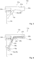
- Fig. 4 and Fig. 5 show a further embodiment of a Hob device 10b according to the invention with a Gargeschirrhandgriff 12b, which is intended to be detachably mounted in an operating state on a cooking utensil 14b.
- the cooking utensil handle 12b comprises a sensor unit 16b for detecting a cooking characteristic of the cooking utensil 14b.
- the cooking utensil handle 12b has a Evaluation unit 20b for an evaluation of the Garkennulate detected by the sensor unit 16b, wherein the evaluation unit 20b is provided for communication with a hob control unit 22b of the hob device 10b.
- the evaluation unit 20b is partially disposed within a support member 32b of the cooking utensil handle 12b.
- the sensor unit 16b has an adjustable sensor element 18b for setting two different measuring positions.
- the adjustable sensor element 18b protrudes partially out of the support member 32b of the cooking utensil handle 12b.
- the sensor unit 16b has a connecting element 36b, which is provided to connect the adjustable sensor element 18b to the carrier component 32b.
- the connecting element 36b is substantially strip-shaped.
- the connecting element 36b is formed of a substantially stable and flexible material, wherein the connecting element 36b is formed of steel.
- the adjustable sensor element 18b has a transmission element 38b for transmitting the cooking parameter to the evaluation unit 20b.
- the transmission element 38b is designed as a transmission module and provided for a wireless transmission of the cooking parameter. Alternatively, it is conceivable that the transmission element is partially disposed within the connecting element and formed as an electrical wire.
- the adjustable sensor element 18b is partially designed as a contact sensor.
- the adjustable sensor element 18b is arranged on the connecting element 36b.
- the adjustable sensor element 18b is fastened to the connecting element 36b at an end of the connecting element 36b which is remote from the carrier component 32b.
- the connecting element 36b has a predefined orientation (see dashed representation of the connecting element in FIG Fig. 4 ). If the fastener 36b in the fastened state, in which the garland handle 12b is removably attached to the cooking utensil 14b, retained the predefined orientation, then the adjustable sensor element 18b would be located on a side of a side wall of the cooking utensil 14b opposite the support member 32b.
- the connecting element 36b would cut the side wall of the cooking utensil 14b.
- the adjustable sensor element 18b is pressed against the cooking utensil 14b.
- the adjustable sensor element 18b is in direct contact with the cooking utensil 14b arranged.
- the adjustable sensor element 18b is arranged at a distance from the carrier component 32b in an operating state.
- the connecting element 36b is arranged partially within the carrier component 32b and partially outside the carrier component 32b.
- the cooking utensil handle 12b comprises a cavity 40b in which the connecting element 36b is mounted in the carrier component 32b.
- the cavity 40b forms a running surface of the connecting member 36b.
- the connecting element 36b is movably mounted in the carrier component 32b.
- the cooktop apparatus 10b includes a gear unit 24b, which is provided to transmit a setting force into a movement of the connecting element 36b and thus of the adjustable sensor element 18b.
- the gear unit 24b has an adjusting member 42b for adjusting the adjusting force.
- the adjusting element 42b is substantially round.
- the adjusting member 42b is formed substantially as a gear.
- the adjusting element could be designed as an electrical component and / or as a mechanical component different from a gear.
- the gear unit 24b is partially formed integrally with the adjusting member 42b.
- the transmission unit 24b is intended to be operated by an operator.
- the gear unit 24b projects partially out of the support member 32b to be operable by an operator.
- the transmission unit 24b is provided for transmitting a setting force into a movement of the adjustable sensor element 18b.
- the connecting element 36b has structural elements 44b, which engage with the gear unit 24b.
- the structural elements 44b are formed as recesses and the adjusting element 42b is designed as a gear corresponding to the recesses.
- the structural elements could be formed as bulges, wherein the adjustment element could have recesses corresponding to the bulges.
- With a partial area arranged essentially within the carrier component 32b the gear unit 24b is in engagement with the structural elements 44b of the connecting element 36b.
- the adjustable sensor element 18b is moved starting from a first measuring position (cf. Fig. 4 ) in a second measuring position (see. Fig. 5 ) emotional. If the adjusting element 42b is actuated in a second direction, which is oriented counter to the first direction, the adjusting element 42b is moved from the second measuring position back into the first measuring position.
- the gear unit has a triggering element, which moves the connecting element in an initial position within the support member in the case of actuation.
- an adjustment of measuring positions of the adjustable sensor element 18b is reversible.
- the sensor unit has a plurality of sensor elements, wherein the sensor unit could, for example, have a plurality of infrared sensors and / or a plurality of contact sensors.
Claims (10)
- Dispositif de champ de cuisson avec au moins une poignée d'élément de batterie de cuisine (12a-b), prévue afin d'être fixée de manière amovible à au moins un élément de batterie de cuisine (14a-b) dans au moins un état de fonctionnement et qui englobe au moins une unité de capteurs (16a-b) au moins pour une détection d'une grandeur caractéristique de cuisson de l'élément de batterie de cuisine (14a-b), caractérisé en ce que l'unité de capteurs (16a-b) présente au moins un élément de capteurs déplaçable (18a-b) pour le réglage d'au moins deux positions de mesure différentes.
- Dispositif de champ de cuisson selon la revendication 1, caractérisé en ce que l'élément de capteurs déplaçable (18a-b) est un élément de capteurs disposé de façon déplaçable sur la poignée d'élément de batterie de cuisine (12a-b), lequel élément est prévu afin d'adopter, dans au moins un premier état de fonctionnement, une première position de mesure et, dans au moins un deuxième état de fonctionnement, une deuxième position de mesure, différente de la première position de mesure.
- Dispositif de champ de cuisson selon l'une des revendications précédentes, caractérisé en ce que la poignée d'élément de batterie de cuisine (12a-b) présente au moins une unité d'évaluation (20a-b) en vue d'une évaluation de la grandeur caractéristique de cuisson détectée par l'unité de capteurs (16a-b).
- Dispositif de champ de cuisson selon la revendication 3, caractérisé en ce que l'unité d'évaluation (20a-b) est prévue pour une communication avec au moins une unité de commande de champ de cuisson (22a-b).
- Dispositif de champ de cuisson selon l'une des revendications précédentes, caractérisé en ce que l'élément de capteurs déplaçable (18a) est au moins partiellement exécuté sous la forme d'un capteur à infrarouges.
- Dispositif de champ de cuisson selon l'une des revendications précédentes, caractérisé en ce que l'élément de capteurs déplaçable (18b) est au moins partiellement exécuté sous la forme d'un capteur de contact.
- Dispositif de champ de cuisson selon l'une des revendications 5 ou 6, caractérisé en ce que l'élément de capteurs déplaçable (18a-b) fait au moins partiellement saillie d'au moins un composant support (32a-b) de la poignée d'élément de batterie de cuisine (12a-b).
- Dispositif de champ de cuisson selon l'une des revendications précédentes, caractérisé par au moins une unité de transmission (24a-b) pour la transposition d'une force de réglage en un déplacement de l'élément de capteurs déplaçable (18a-b).
- Champ de cuisson avec au moins un dispositif de champ de cuisson (10a-b) selon l'une des revendications 1 à 8.
- Procédé d'exploitation d'un dispositif de champ de cuisson (10a-b) selon l'une des revendications 1 à 8, avec au moins une poignée d'élément de batterie de cuisine (12a-b), prévue afin d'être fixée de manière amovible à au moins un élément de batterie de cuisine (14a-b) dans au moins un état de fonctionnement et qui englobe au moins une unité de capteurs (16a-b), une grandeur caractéristique de cuisson de l'élément de batterie de cuisine (14a-b) étant détectée par l'unité de capteurs (16a-b) et dans lequel l'unité de capteurs (16a-b) présente au moins un élément de capteurs déplaçable (18a-b) pour le réglage d'au moins deux positions de mesure différentes.
Applications Claiming Priority (1)
| Application Number | Priority Date | Filing Date | Title |
|---|---|---|---|
| ES201331064 | 2013-07-12 |
Publications (2)
| Publication Number | Publication Date |
|---|---|
| EP2823740A1 EP2823740A1 (fr) | 2015-01-14 |
| EP2823740B1 true EP2823740B1 (fr) | 2018-02-28 |
Family
ID=51257270
Family Applications (1)
| Application Number | Title | Priority Date | Filing Date |
|---|---|---|---|
| EP14175865.6A Active EP2823740B1 (fr) | 2013-07-12 | 2014-07-04 | Dispositif de plaque de cuisson |
Country Status (1)
| Country | Link |
|---|---|
| EP (1) | EP2823740B1 (fr) |
Families Citing this family (3)
| Publication number | Priority date | Publication date | Assignee | Title |
|---|---|---|---|---|
| ES2590427B1 (es) * | 2015-05-21 | 2017-09-07 | Bsh Electrodomésticos España, S.A. | Sistema de cocción |
| ES2646441B1 (es) * | 2016-06-09 | 2019-02-07 | Bsh Electrodomesticos Espana Sa | Dispositivo de medicion de aparato de coccion |
| DE102019104003A1 (de) * | 2019-02-18 | 2020-08-20 | Miele & Cie. Kg | Verfahren zur automatischen Zuordnung eines Aufstellgeräts zu einer Kochstelle eines induktiven Kochfelds, Aufstellgerät und System zur Durchführung des Verfahrens |
Citations (2)
| Publication number | Priority date | Publication date | Assignee | Title |
|---|---|---|---|---|
| WO2004008923A2 (fr) * | 2002-07-24 | 2004-01-29 | Richard Sharpe | Systemes et procedes de poele electronique |
| DE20318327U1 (de) * | 2003-11-25 | 2005-04-14 | Wenzler, Heidelinde | Kochgutüberhitzungssignalgeber |
Family Cites Families (4)
| Publication number | Priority date | Publication date | Assignee | Title |
|---|---|---|---|---|
| DE4439777A1 (de) * | 1994-11-07 | 1996-05-15 | Bosch Siemens Hausgeraete | Sensorgesteuerte Glaskeramik-Kochstelleneinheit |
| US7157675B2 (en) * | 2004-04-28 | 2007-01-02 | Imura International U.S.A. Inc. | Radio frequency identification controlled heatable objects |
| KR101656115B1 (ko) * | 2009-01-06 | 2016-09-08 | 액세스 비지니스 그룹 인터내셔날 엘엘씨 | 스마트 조리 기구 |
| FR2977776B1 (fr) * | 2011-07-13 | 2014-05-23 | Seb Sa | Article culinaire alimente par induction et procede pour fabriquer le recipient d'un tel article |
-
2014
- 2014-07-04 EP EP14175865.6A patent/EP2823740B1/fr active Active
Patent Citations (2)
| Publication number | Priority date | Publication date | Assignee | Title |
|---|---|---|---|---|
| WO2004008923A2 (fr) * | 2002-07-24 | 2004-01-29 | Richard Sharpe | Systemes et procedes de poele electronique |
| DE20318327U1 (de) * | 2003-11-25 | 2005-04-14 | Wenzler, Heidelinde | Kochgutüberhitzungssignalgeber |
Also Published As
| Publication number | Publication date |
|---|---|
| EP2823740A1 (fr) | 2015-01-14 |
Similar Documents
| Publication | Publication Date | Title |
|---|---|---|
| DE102008064731B4 (de) | Kochfeld mit einem bewegbaren Heizelement | |
| EP2823740B1 (fr) | Dispositif de plaque de cuisson | |
| EP3560281B1 (fr) | Dispositif pour appareil de cuisson | |
| EP3028535B1 (fr) | Système de table de cuisson | |
| EP2833697B1 (fr) | Dispositif de plaque de cuisson | |
| EP3096586B1 (fr) | Système de cuisson | |
| DE102014216709A1 (de) | Kochfeldvorrichtung | |
| EP2824393B1 (fr) | Dispositif de plaque de cuisson | |
| EP3082378B1 (fr) | Plaque de cuisson | |
| EP3297506A1 (fr) | Dispositif table de cuisson | |
| EP2921830A2 (fr) | Dispositif d'appareil ménager | |
| EP3273751A1 (fr) | Plaque de cuisson | |
| EP3273211A2 (fr) | Dispositif de détection ir pour mesurer la température d'un aliment | |
| EP3735884A1 (fr) | Système de cuisson | |
| EP3509392B1 (fr) | Procédé pour une plaque de cuisson | |
| EP3096588B1 (fr) | Plaque de cuisson | |
| EP3028538A1 (fr) | Système de table de cuisson | |
| WO2020079609A1 (fr) | Dispositif à induction | |
| EP2843315A2 (fr) | Système destiné à assembler au moins un dispositif d'appareil ménager et un appareil ménager | |
| EP3383139A1 (fr) | Dispositif d'appareil de cuisson | |
| WO2020079611A1 (fr) | Dispositif à induction | |
| WO2020079625A1 (fr) | Dispositif à induction | |
| EP2989945B1 (fr) | Robot menager dote d'un recipient pouvant etre chauffe | |
| EP2879464B1 (fr) | Dispositif d'appareil ménager | |
| DE102019207933A1 (de) | Küchensystem und Verfahren zu einem Betrieb eines Küchensystems |
Legal Events
| Date | Code | Title | Description |
|---|---|---|---|
| 17P | Request for examination filed |
Effective date: 20140704 |
|
| AK | Designated contracting states |
Kind code of ref document: A1 Designated state(s): AL AT BE BG CH CY CZ DE DK EE ES FI FR GB GR HR HU IE IS IT LI LT LU LV MC MK MT NL NO PL PT RO RS SE SI SK SM TR |
|
| AX | Request for extension of the european patent |
Extension state: BA ME |
|
| PUAI | Public reference made under article 153(3) epc to a published international application that has entered the european phase |
Free format text: ORIGINAL CODE: 0009012 |
|
| RAP1 | Party data changed (applicant data changed or rights of an application transferred) |
Owner name: BSH HAUSGERAETE GMBH |
|
| R17P | Request for examination filed (corrected) |
Effective date: 20150714 |
|
| RBV | Designated contracting states (corrected) |
Designated state(s): AL AT BE BG CH CY CZ DE DK EE ES FI FR GB GR HR HU IE IS IT LI LT LU LV MC MK MT NL NO PL PT RO RS SE SI SK SM TR |
|
| 17Q | First examination report despatched |
Effective date: 20160205 |
|
| REG | Reference to a national code |
Ref country code: DE Ref legal event code: R079 Ref document number: 502014007421 Country of ref document: DE Free format text: PREVIOUS MAIN CLASS: A47J0045100000 Ipc: H05B0006120000 |
|
| RIC1 | Information provided on ipc code assigned before grant |
Ipc: H05B 6/12 20060101AFI20170822BHEP Ipc: A47J 27/62 20060101ALI20170822BHEP Ipc: A47J 36/32 20060101ALI20170822BHEP Ipc: A47J 45/07 20060101ALI20170822BHEP |
|
| GRAP | Despatch of communication of intention to grant a patent |
Free format text: ORIGINAL CODE: EPIDOSNIGR1 |
|
| INTG | Intention to grant announced |
Effective date: 20170929 |
|
| GRAS | Grant fee paid |
Free format text: ORIGINAL CODE: EPIDOSNIGR3 |
|
| GRAA | (expected) grant |
Free format text: ORIGINAL CODE: 0009210 |
|
| AK | Designated contracting states |
Kind code of ref document: B1 Designated state(s): AL AT BE BG CH CY CZ DE DK EE ES FI FR GB GR HR HU IE IS IT LI LT LU LV MC MK MT NL NO PL PT RO RS SE SI SK SM TR |
|
| REG | Reference to a national code |
Ref country code: GB Ref legal event code: FG4D Free format text: NOT ENGLISH Ref country code: CH Ref legal event code: EP |
|
| REG | Reference to a national code |
Ref country code: AT Ref legal event code: REF Ref document number: 975486 Country of ref document: AT Kind code of ref document: T Effective date: 20180315 |
|
| REG | Reference to a national code |
Ref country code: IE Ref legal event code: FG4D Free format text: LANGUAGE OF EP DOCUMENT: GERMAN |
|
| REG | Reference to a national code |
Ref country code: DE Ref legal event code: R096 Ref document number: 502014007421 Country of ref document: DE |
|
| REG | Reference to a national code |
Ref country code: NL Ref legal event code: MP Effective date: 20180228 |
|
| REG | Reference to a national code |
Ref country code: LT Ref legal event code: MG4D |
|
| PG25 | Lapsed in a contracting state [announced via postgrant information from national office to epo] |
Ref country code: FI Free format text: LAPSE BECAUSE OF FAILURE TO SUBMIT A TRANSLATION OF THE DESCRIPTION OR TO PAY THE FEE WITHIN THE PRESCRIBED TIME-LIMIT Effective date: 20180228 Ref country code: CY Free format text: LAPSE BECAUSE OF FAILURE TO SUBMIT A TRANSLATION OF THE DESCRIPTION OR TO PAY THE FEE WITHIN THE PRESCRIBED TIME-LIMIT Effective date: 20180228 Ref country code: LT Free format text: LAPSE BECAUSE OF FAILURE TO SUBMIT A TRANSLATION OF THE DESCRIPTION OR TO PAY THE FEE WITHIN THE PRESCRIBED TIME-LIMIT Effective date: 20180228 Ref country code: NL Free format text: LAPSE BECAUSE OF FAILURE TO SUBMIT A TRANSLATION OF THE DESCRIPTION OR TO PAY THE FEE WITHIN THE PRESCRIBED TIME-LIMIT Effective date: 20180228 Ref country code: ES Free format text: LAPSE BECAUSE OF FAILURE TO SUBMIT A TRANSLATION OF THE DESCRIPTION OR TO PAY THE FEE WITHIN THE PRESCRIBED TIME-LIMIT Effective date: 20180228 Ref country code: HR Free format text: LAPSE BECAUSE OF FAILURE TO SUBMIT A TRANSLATION OF THE DESCRIPTION OR TO PAY THE FEE WITHIN THE PRESCRIBED TIME-LIMIT Effective date: 20180228 Ref country code: NO Free format text: LAPSE BECAUSE OF FAILURE TO SUBMIT A TRANSLATION OF THE DESCRIPTION OR TO PAY THE FEE WITHIN THE PRESCRIBED TIME-LIMIT Effective date: 20180528 |
|
| PG25 | Lapsed in a contracting state [announced via postgrant information from national office to epo] |
Ref country code: BG Free format text: LAPSE BECAUSE OF FAILURE TO SUBMIT A TRANSLATION OF THE DESCRIPTION OR TO PAY THE FEE WITHIN THE PRESCRIBED TIME-LIMIT Effective date: 20180528 Ref country code: RS Free format text: LAPSE BECAUSE OF FAILURE TO SUBMIT A TRANSLATION OF THE DESCRIPTION OR TO PAY THE FEE WITHIN THE PRESCRIBED TIME-LIMIT Effective date: 20180228 Ref country code: SE Free format text: LAPSE BECAUSE OF FAILURE TO SUBMIT A TRANSLATION OF THE DESCRIPTION OR TO PAY THE FEE WITHIN THE PRESCRIBED TIME-LIMIT Effective date: 20180228 Ref country code: LV Free format text: LAPSE BECAUSE OF FAILURE TO SUBMIT A TRANSLATION OF THE DESCRIPTION OR TO PAY THE FEE WITHIN THE PRESCRIBED TIME-LIMIT Effective date: 20180228 |
|
| PG25 | Lapsed in a contracting state [announced via postgrant information from national office to epo] |
Ref country code: MT Free format text: LAPSE BECAUSE OF FAILURE TO SUBMIT A TRANSLATION OF THE DESCRIPTION OR TO PAY THE FEE WITHIN THE PRESCRIBED TIME-LIMIT Effective date: 20180228 |
|
| PG25 | Lapsed in a contracting state [announced via postgrant information from national office to epo] |
Ref country code: PL Free format text: LAPSE BECAUSE OF FAILURE TO SUBMIT A TRANSLATION OF THE DESCRIPTION OR TO PAY THE FEE WITHIN THE PRESCRIBED TIME-LIMIT Effective date: 20180228 Ref country code: EE Free format text: LAPSE BECAUSE OF FAILURE TO SUBMIT A TRANSLATION OF THE DESCRIPTION OR TO PAY THE FEE WITHIN THE PRESCRIBED TIME-LIMIT Effective date: 20180228 Ref country code: RO Free format text: LAPSE BECAUSE OF FAILURE TO SUBMIT A TRANSLATION OF THE DESCRIPTION OR TO PAY THE FEE WITHIN THE PRESCRIBED TIME-LIMIT Effective date: 20180228 Ref country code: AL Free format text: LAPSE BECAUSE OF FAILURE TO SUBMIT A TRANSLATION OF THE DESCRIPTION OR TO PAY THE FEE WITHIN THE PRESCRIBED TIME-LIMIT Effective date: 20180228 Ref country code: IT Free format text: LAPSE BECAUSE OF FAILURE TO SUBMIT A TRANSLATION OF THE DESCRIPTION OR TO PAY THE FEE WITHIN THE PRESCRIBED TIME-LIMIT Effective date: 20180228 |
|
| REG | Reference to a national code |
Ref country code: DE Ref legal event code: R097 Ref document number: 502014007421 Country of ref document: DE |
|
| PG25 | Lapsed in a contracting state [announced via postgrant information from national office to epo] |
Ref country code: CZ Free format text: LAPSE BECAUSE OF FAILURE TO SUBMIT A TRANSLATION OF THE DESCRIPTION OR TO PAY THE FEE WITHIN THE PRESCRIBED TIME-LIMIT Effective date: 20180228 Ref country code: DK Free format text: LAPSE BECAUSE OF FAILURE TO SUBMIT A TRANSLATION OF THE DESCRIPTION OR TO PAY THE FEE WITHIN THE PRESCRIBED TIME-LIMIT Effective date: 20180228 Ref country code: SM Free format text: LAPSE BECAUSE OF FAILURE TO SUBMIT A TRANSLATION OF THE DESCRIPTION OR TO PAY THE FEE WITHIN THE PRESCRIBED TIME-LIMIT Effective date: 20180228 Ref country code: SK Free format text: LAPSE BECAUSE OF FAILURE TO SUBMIT A TRANSLATION OF THE DESCRIPTION OR TO PAY THE FEE WITHIN THE PRESCRIBED TIME-LIMIT Effective date: 20180228 |
|
| PLBE | No opposition filed within time limit |
Free format text: ORIGINAL CODE: 0009261 |
|
| STAA | Information on the status of an ep patent application or granted ep patent |
Free format text: STATUS: NO OPPOSITION FILED WITHIN TIME LIMIT |
|
| 26N | No opposition filed |
Effective date: 20181129 |
|
| PG25 | Lapsed in a contracting state [announced via postgrant information from national office to epo] |
Ref country code: SI Free format text: LAPSE BECAUSE OF FAILURE TO SUBMIT A TRANSLATION OF THE DESCRIPTION OR TO PAY THE FEE WITHIN THE PRESCRIBED TIME-LIMIT Effective date: 20180228 |
|
| REG | Reference to a national code |
Ref country code: CH Ref legal event code: PL |
|
| GBPC | Gb: european patent ceased through non-payment of renewal fee |
Effective date: 20180704 |
|
| PG25 | Lapsed in a contracting state [announced via postgrant information from national office to epo] |
Ref country code: MC Free format text: LAPSE BECAUSE OF FAILURE TO SUBMIT A TRANSLATION OF THE DESCRIPTION OR TO PAY THE FEE WITHIN THE PRESCRIBED TIME-LIMIT Effective date: 20180228 Ref country code: LU Free format text: LAPSE BECAUSE OF NON-PAYMENT OF DUE FEES Effective date: 20180704 |
|
| REG | Reference to a national code |
Ref country code: BE Ref legal event code: MM Effective date: 20180731 |
|
| REG | Reference to a national code |
Ref country code: IE Ref legal event code: MM4A |
|
| PG25 | Lapsed in a contracting state [announced via postgrant information from national office to epo] |
Ref country code: FR Free format text: LAPSE BECAUSE OF NON-PAYMENT OF DUE FEES Effective date: 20180731 Ref country code: IE Free format text: LAPSE BECAUSE OF NON-PAYMENT OF DUE FEES Effective date: 20180704 Ref country code: CH Free format text: LAPSE BECAUSE OF NON-PAYMENT OF DUE FEES Effective date: 20180731 Ref country code: LI Free format text: LAPSE BECAUSE OF NON-PAYMENT OF DUE FEES Effective date: 20180731 Ref country code: GB Free format text: LAPSE BECAUSE OF NON-PAYMENT OF DUE FEES Effective date: 20180704 |
|
| PG25 | Lapsed in a contracting state [announced via postgrant information from national office to epo] |
Ref country code: BE Free format text: LAPSE BECAUSE OF NON-PAYMENT OF DUE FEES Effective date: 20180731 |
|
| PG25 | Lapsed in a contracting state [announced via postgrant information from national office to epo] |
Ref country code: TR Free format text: LAPSE BECAUSE OF FAILURE TO SUBMIT A TRANSLATION OF THE DESCRIPTION OR TO PAY THE FEE WITHIN THE PRESCRIBED TIME-LIMIT Effective date: 20180228 |
|
| PG25 | Lapsed in a contracting state [announced via postgrant information from national office to epo] |
Ref country code: PT Free format text: LAPSE BECAUSE OF FAILURE TO SUBMIT A TRANSLATION OF THE DESCRIPTION OR TO PAY THE FEE WITHIN THE PRESCRIBED TIME-LIMIT Effective date: 20180228 Ref country code: HU Free format text: LAPSE BECAUSE OF FAILURE TO SUBMIT A TRANSLATION OF THE DESCRIPTION OR TO PAY THE FEE WITHIN THE PRESCRIBED TIME-LIMIT; INVALID AB INITIO Effective date: 20140704 |
|
| PG25 | Lapsed in a contracting state [announced via postgrant information from national office to epo] |
Ref country code: MK Free format text: LAPSE BECAUSE OF NON-PAYMENT OF DUE FEES Effective date: 20180228 Ref country code: GR Free format text: LAPSE BECAUSE OF FAILURE TO SUBMIT A TRANSLATION OF THE DESCRIPTION OR TO PAY THE FEE WITHIN THE PRESCRIBED TIME-LIMIT Effective date: 20180228 |
|
| PG25 | Lapsed in a contracting state [announced via postgrant information from national office to epo] |
Ref country code: IS Free format text: LAPSE BECAUSE OF FAILURE TO SUBMIT A TRANSLATION OF THE DESCRIPTION OR TO PAY THE FEE WITHIN THE PRESCRIBED TIME-LIMIT Effective date: 20180628 |
|
| REG | Reference to a national code |
Ref country code: AT Ref legal event code: MM01 Ref document number: 975486 Country of ref document: AT Kind code of ref document: T Effective date: 20190704 |
|
| PG25 | Lapsed in a contracting state [announced via postgrant information from national office to epo] |
Ref country code: AT Free format text: LAPSE BECAUSE OF NON-PAYMENT OF DUE FEES Effective date: 20190704 |
|
| PGFP | Annual fee paid to national office [announced via postgrant information from national office to epo] |
Ref country code: DE Payment date: 20230731 Year of fee payment: 10 |