EP2822238B1 - Verfahren und Vorrichtung zur Herstellung einer Pseudowire-Verbindung - Google Patents
Verfahren und Vorrichtung zur Herstellung einer Pseudowire-Verbindung Download PDFInfo
- Publication number
- EP2822238B1 EP2822238B1 EP14180989.7A EP14180989A EP2822238B1 EP 2822238 B1 EP2822238 B1 EP 2822238B1 EP 14180989 A EP14180989 A EP 14180989A EP 2822238 B1 EP2822238 B1 EP 2822238B1
- Authority
- EP
- European Patent Office
- Prior art keywords
- control message
- identification information
- information
- switching node
- node
- Prior art date
- Legal status (The legal status is an assumption and is not a legal conclusion. Google has not performed a legal analysis and makes no representation as to the accuracy of the status listed.)
- Active
Links
Images


Classifications
-
- H—ELECTRICITY
- H04—ELECTRIC COMMUNICATION TECHNIQUE
- H04L—TRANSMISSION OF DIGITAL INFORMATION, e.g. TELEGRAPHIC COMMUNICATION
- H04L45/00—Routing or path finding of packets in data switching networks
- H04L45/68—Pseudowire emulation, e.g. IETF WG PWE3
-
- H—ELECTRICITY
- H04—ELECTRIC COMMUNICATION TECHNIQUE
- H04L—TRANSMISSION OF DIGITAL INFORMATION, e.g. TELEGRAPHIC COMMUNICATION
- H04L45/00—Routing or path finding of packets in data switching networks
- H04L45/02—Topology update or discovery
Definitions
- the present invention relates to the field of communications, and in particular, to a method, a device and a system for establishing a Pseudo Wire.
- a Pseudo Wire provides a service emulation technology, including a point to point method and a point to multipoint method.
- a Provider Edge (PE) equipment performs simulation on user data through operations of encapsulation and decapsulation of received Customer Edge (CE) data.
- the PW may be applied in a Layer 2 Virtual Private Network (L2VPN), and may be used to provide a Virtual Private Wire Service (VPWS), and a Virtual Private LAN Service (VPLS).
- L2VPN Layer 2 Virtual Private Network
- VPWS Virtual Private Wire Service
- VPLS Virtual Private LAN Service
- MS-PW Multi-Segment Pseudo Wire
- PSNs Provider Service Networks
- MS-PWs are also needed.
- the services such as Time Division Multiplexer (TDM) and Asynchronous Transfer Mode (ATM) must be transmitted by Pseudo Wire between Cell Site Gateway (CSG) and Mobile Aggregation Site Gateway (MASG). Because masses of CSGs, the targeted label distribution protocol (T-LDP) sessions is the challenge for MASG, MS-PWs are also required.
- TDM Time Division Multiplexer
- ATM Asynchronous Transfer Mode
- T-LDP targeted label distribution protocol
- the MS-PW could be deployed via static configuration or dynamic protocols.
- a MS-PW should be established segment by segment, then mapping relations between PW segments are established.
- PW105 and PW115 between the terminal node 100 and a switching node 120
- PW125 and PW135 between the switching node 120 and the terminal node 140
- mapping relations for PW segments on the switching node 120 for example, mapping relations between PW Identifiers (IDs), such as a mapping relation between a PW ID of PW105 and a PW ID of PW125, and a mapping relation between a PW ID of PW 115 and a PW ID of PW135.
- IDs mapping relations between PW Identifiers
- the PW between the terminal node 100 and the terminal node 140 is deployed.
- the workload for manual configuration is very heavy; additionally maintenance of MS-PWs is complicated.
- the PW could be established dynamically by two steps: statically configuring or dynamically establishing a PW routing table, establishing the MS-PW by using Label Distribution Protocol (LDP).
- LDP Label Distribution Protocol
- FIG. 1 in order to establish PWs between the terminal node 100 and the terminal node 140, it first needs to establish a PW routing table via manually configuring or a routing protocol on the switching node 120. Then, the terminal node 100 sends LDP signaling for establishing PW segments between the terminal node 100 and the switching node 120. After receiving the LDP signaling, the switching node 120 queries the configured PW routing table, and then initiates LDP signaling for establishing PW segments between the switching node 120 and the terminal node 140.
- LDP Label Distribution Protocol
- a PW routing table must be deployed on a switching via manually configuring or dynamically based on a complicated protocol Therefore, when multiple switching nodes or multiple MS-PWs exist, the workload of manually configuring the PW routing table on the switching node is very heavy. On the other hand, there is a strict capability requirement for equipment in order to introduce routing protocols. In addition, it is complicated to establish the PW routing table.
- Multi-Segment Pseudowire Setup and Maintenance using LDP provides a MS-PW Operational Model, Signaling Procedures consistent with the regular (SS-) PWs, in order to enable seamless implementation, deployment.
- the resulting solutions with minimal changes in the Information Models and Software Modules related to the L2VPN functionality.
- An embodiment of the present invention provides methods for establishing a PW, a terminal node and a switching node.
- An embodiment of the present invention provides a method for establishing a PW, where the method includes:
- An embodiment of the present invention provides a terminal node, configured to:
- An embodiment of the present invention provides a method for establishing a Pseudo Wire, PW, comprising:
- An embodiment of the present invention provides a switching node, configured to:
- An embodiment of the present invention provides a system for establishing a PW, where the system includes a first terminal node, a second terminal node and a switching node, and the first terminal node is connected to the second terminal node through the switching node, and
- a control message carries PW routing information, that is, identification information of a passed intermediate switching node, required for establishing a PW between two terminal nodes, so that when receiving the control message, the switching node may forward the control message according to the identification information.
- PW routing information that is, identification information of a passed intermediate switching node, required for establishing a PW between two terminal nodes, so that when receiving the control message, the switching node may forward the control message according to the identification information.
- routing table information required by the PW is not required to be configured manually or established through dynamic signaling, and mapping relations between PWs are not required to be established manually either.
- An intermediate forwarding process is automatically performed by the switching node and is applicable to situations of multiple switching nodes, which may reduce workload caused by manual operations and reduce introduction of complicated dynamic signaling, and is easy for management.
- a PW is to be established between a first terminal node 200 and a second terminal node 220 according to an embodiment of the present invention, where multiple switching nodes may be deployed between the first terminal node 200 and the second terminal node 220, or no switching node may be included between the first terminal node 200 and the second terminal node 220.
- a method used when no switching node is included is the same as that in the prior art, so the method is not described herein.
- a situation that two switching nodes are deployed between the first terminal node 200 and the second terminal node 220 is taken as an example, where the two switching nodes are a switching node 205 and a switching node 215.
- the first terminal node 200 and the second terminal node 220 may be a terminal node provider edge router (TPE), and the switching node 205 and the switching node 215 may be a switching node provider edge router (SPE).
- TPE terminal node provider edge router
- SPE switching node provider edge router
- An embodiment of the present invention provides a method for establishing a PW, and the idea of the method is to send a control message carrying routing information between the first terminal node 200 and the second terminal node 220, where the routing information includes identification information of an intermediate switching node.
- the intermediate switching node may forward the message according to the routing information in the control message.
- FIG. 3 A specific process is as shown in FIG. 3 , which includes the following steps:
- the control message may be an existing label mapping message, for example, a Label Mapping message, and the PW label carried in the control message is a PW label assigned to a next node by the first terminal node 200.
- the PW label in this embodiment is Label1, a structure of which may be similar to that of an existing Label Switched Path (LSP) label.
- LSP Label Switched Path
- the first FEC information is shown in FIG. 4 , which includes, but is not limited to:
- the information carried by the SAII in the control message may be used to identify the first terminal node 200, and the information carried by the TAII may be used to identify the second terminal node 220.
- the first routing information carries identification information of switching nodes between the first terminal node 200 and the second terminal node 220 to establish a PW.
- the first routing information carries identification information of the switching node 205 and the switching node 215.
- the first routing information may be carried in a Type-Length-Value (TLV) parameter of the control message.
- TLV Type-Length-Value
- a structure of the TLV parameter carrying the first routing information may be shown in Table 1.
- Table 1 TYPE Length Identification information of the switching node 205 Identification information of the switching node 215
- a structure of the TLV parameter carrying the first routing information may also be shown in Table 2.
- Table 2 TYPE Length ER-hop TLV1 ER-hop TLV2
- the value of Content of the ER-hop TLV1 is the identification information of the switching node 205
- the value of Content of the ER-hop TLV2 is the identification information of the switching node 215.
- the identification information of the switching node may be an equipment ID or an IP address of the switching node, or one of other identification information of the switching node.
- the first terminal node 200 sends the control message to a corresponding switching node, which is the switching node 205 in this embodiment, according to the identification information of a first switching node in the first routing information.
- Step 310 The switching node 205 assigns a PW label Label2, and sends the control message carrying Label2 to the switching node 215.
- the switching node 205 After receiving the control message, the switching node 205 analyzes the first routing information in the control message, obtains the PW label Label1 in the control message, and saves the PW label Label1. As a PW label assigned to this switching node by the first terminal node 200, Label1 is used to identify a segmented PW from this switching node to the first terminal node 200. The switching node 205 assigns a PW label Label2, a format of which may be similar to that of an LSP label, and may be the same as that of Label1 or may be different from that of Label1.
- the switching node 205 constructs a control message carrying Label2, the first FEC information and the first routing information, obtains identification information of a next switching node of the identification information of the switching node 205 in the first routing information, and sends the control message carrying Label2 to a switching node corresponding to the obtained identification information, that is, the switching node 215 in this embodiment.
- Step 320 The switching node 215 assigns a PW label Label3, and sends the first control message carrying Label3 to the second terminal node 220.
- the switching node 215 After receiving the control message, the switching node 215 analyzes the first routing information in the control message, obtains the PW label Label2 in the control message, and saves the PW label Label2. As a PW label assigned to this switching node by the switching node 205, Label2 is used to identify a segmented PW from this switching node to the switching node 205.
- the switching node 215 assigns a PW label Label3, a format of which may be similar to that of the LSP label, and may be the same as that of Label2 or may be different from that of Label2.
- the switching node 215 constructs the first control message carrying Label3, the first FEC information and the first routing information.
- the switching node 215 obtains next identification information of the identification information of the switching node 215 in the first routing information. A next ID does not exist, so the switching node 215 reads a value of a TAII field of the first FEC information in the first control message, and sends the first control message carrying Label3 to the second terminal node 220 according to the obtained value.
- Step 330 The second terminal node 220 constructs a second control message carrying a PW label, second FEC information and second routing information, and sends the second control message to the switching node 215.
- the second terminal node 220 saves Label3, which is assigned to the second terminal node 220 by the switching node 215.
- Label 3 is used to identify a segmented PW between the switching node 215 and the second terminal node 220.
- the second terminal node 220 assigns a PW label Label4, and constructs the second control message carrying Label4, the second FEC information and the second routing information, where Label4 may be the same as Label3 or may be different from Label3, and a format of Label4 may be similar to that of an LSP label.
- the method of constructing the second control message by the second terminal node 220 is as follows: (1) If the second FEC information is configured on the second terminal node 220, an SAII field of the second FEC information carries identification information of the second terminal node 220, and the TAII field carries identification information of the first terminal node 200.
- the second terminal node 220 analyzes the first routing information in the first control message, and generates the second routing information based on the first routing information.
- the generated second routing information carries the identification information of the switching node in the first routing information.
- the second routing information may be included in a TLV parameter, and a structure of the TLV parameter may be shown in Table 4. Table 4 TYPE Length Identification information of the switching node 215 Identification information of the switching node 205
- the structure may also be shown in Table 5.
- Table 5 TYPE Length ER-hop TLV2 ER-hop TLV1
- a Content field of the ER-hop TLV2 carries the identification information of the switching node 215, and a Content field of the ER-hop TLV1 carries the identification information of the switching node 205.
- the second terminal node 220 constructs the second control message carrying the second FEC information, Label4 and the second routing information.
- the second terminal node 220 generates the second routing information according to the first routing information in the first control message. First, the second terminal node 220 analyzes the first routing information in the first control message and generating the second routing information that is shown in Table 4 or Table 5.
- the second terminal node 220 constructs the second control message carrying the second FEC information, Label4 and the second routing information.
- the choosing of the above two methods depends on a policy set on the second terminal node 220. For example, no matter whether the second FEC information is configured with the value of the TAII, the second terminal node 220 needs to analyze the first FEC information. The second terminal node 220 may also determine which method to choose. For example, when the value of the TAII is configured in the second FEC information on terminal node 220, the second terminal node 220 chooses the first method; when the value of the TAII is not configured in the second FEC information, the second terminal node 220 chooses the second method.
- the second terminal node 220 sends the second control message to a corresponding switching node, which is the switching node 215 in this embodiment, according to the first identification information in the second routing information.
- Step 340 The switching node 215 assigns a PW label Label5, and sends a third control message carrying Label5 to the switching node 205.
- the switching node 215 After receiving the second control message, the switching node 215 analyzes the second routing information in the second control message, obtains Label4 in the second control message, and saves Label4.
- the Label 4 is used as a PW label, which is assigned to this switching node by the second terminal node 220.
- Label4 is used to identify a segmented PW from this switching node to the second terminal node 220.
- the switching node 215 assigns the PW label Label5, which may be the same as Label4 or may be different from Label4.
- the switching node 215 constructs the third control message carrying Label5, the second FEC information and the second routing information, obtains next identification information of the identification information of the switching node 215 in the second routing information, and sends the third control message carrying Label5 to a switching node corresponding to the obtained next identification information, which is the switching node 205 in this embodiment.
- Step 350 The switching node 205 assigns a PW label Label6, and sends a control message carrying Label6 to the first terminal node 200.
- the switching node 205 After receiving the third control message, the switching node 205 analyzes the routing information of the switching node in the third control message, obtains the PW label Label5 in the third control message, and saves the PW label Label5. As a PW label assigned to this switching node by the switching node 215, Label5 is used to identify a segmented PW from this switching node to the switching node 215.
- the switching node 205 assigns a PW label Label6, which may be the same as Label5 or may be different from Label5.
- the switching node 205 constructs a control message carrying Label6, the second FEC information and the second routing information, obtains next identification information of the identification information of the switching node 205. The next identification information does not exist, so the switching node 205 reads the value of the TAII field in the second FEC information of the control message, and sends the second control message carrying Label6 to the first terminal node 200 according to an obtained value.
- the first terminal node 200 saves Label6 as the PW label assigned to the first terminal node 200 by the switching node 205.
- a bidirectional PW is established between the first terminal node 200 and the second terminal node 220.
- the intermediate switching nodes may forward a message according to the routing information carrying the routing information of the intermediate switching nodes in the control message. Therefore, during the establishing process of the PW, it is unnecessary to additionally configure the PW routing node statically on the switching node, or dynamically establish the PW routing table. absolutely, it is unnecessary to manually configure mapping relations between PWs.
- the first routing information in the first control message needs to be analyzed. Based on that, the second terminal node 220 sends the second control message. Then, the second routing information including the identification information of the switching node could be carried in the first control message, rather than be constructed additionally. In this way the second terminal node 220 may directly read the second routing information in the first control message.
- FIG. 5 A specific process of the method is shown in FIG. 5 , which includes the following steps:
- the first terminal node 200 assigns a PW label Label1 to the second terminal node 220, and the format of Label1 may be similar to that of an LSP label.
- the first FEC information is shown in FIG. 4 , which includes the identification information of the first terminal node 200 and the second terminal node 220.
- the first routing information carries the identification information of the switching node 205 and the switching node 215, and a structure may be shown in Table 1 or Table 2.
- the second routing information carries the identification information of the switching node 215 and the switching node 205, and a structure may be shown in Table 4 or Table 5.
- the first terminal node 200 sends the control message to a corresponding switching node, which is the switching node 205 in this embodiment, according to the first identification information of the first routing information.
- Step 510 The switching node 205 assigns a PW label Label2, and sends the control message carrying Label2 to the switching node 215 after removing the identification information of the switching node 205 in the first routing information.
- the switching node 205 After receiving the control message, the switching node 205 analyzes the first routing information in the control message, obtains the PW label Label1 in the control message, saves the PW label Label1, assigns a PW label Label2, obtains the identification information of the next switching node of the identification information (the first identification information) of the switching node 205 in the first routing information, removes the identification information of the switching node 205 in the first routing information in the control message, constructs the control message carrying Label2, the first FEC information, the second routing information, and the first routing information from which the identification information of the switching node 205 is removed, and sends a processed control message to a corresponding switching node, which is the switching node 215 in this embodiment, according to the obtained identification information of the next switching node.
- the switching node 205 After receiving the control message, the switching node 205 analyzes the first routing information in the control message, obtains the PW label Label1 in the control message, saves the PW label Label1, assigns a PW
- Step 520 The switching node 215 assigns a PW label Label3, and sends the first control message carrying Label3 to the second terminal node 220 after removing the identification information of the switching node 215 in the first routing information.
- the switching node 215 After receiving the control message, the switching node 215 analyzes the first routing information in the first control message, obtains the PW label Label2 in the first control message, saves the PW label Label2, assigns a PW label Label3, and obtains the next identification information of the identification information (the first identification information) of the switching node 215 in the first routing information.
- the next identification information does not exist, so the switching node 215 reads the value of the TAII field in the first FEC information in the first control message, removes the identification information of the switching node 215 in the first routing information, constructs the first control message carrying Label3, the first FEC information, the second routing information, and the first routing information from which the identification information of the switching node 215 is removed, and sends the first control message carrying Label3 to the second terminal node 220 according to an obtained value of the TAII.
- Step 530 The second terminal node 220 constructs the second control message including the PW label Label4, the second FEC information and the second routing information, and sends the second control message.
- the second terminal node 220 assigns the PW label Label4, and constructs the second control message according to the first control message, where Label4 may be the same as Label3 or may be different from Label3.
- the method of constructing the second control message by the second terminal node 220 is as follows:
- the second terminal node 220 reads the second routing information in the first control message.
- the second terminal node 220 constructs the second control message carrying the second FEC information, Label4 and the second routing information.
- the second terminal node 220 sends the second control message to a corresponding switching node, which is the switching node 215 in this embodiment, according to the identification information of the first switching node in the second routing information.
- Step 540 The switching node 215 assigns the PW label Label5, and sends the third control message carrying Label5 to the switching node 205 after removing the identification information of the switching node 215 in the second routing information.
- the switching node 215 After receiving the second control message, the switching node 215 analyzes the second routing information in the second control message, obtains Label4 in the second control message, saves Label4, assigns the PW label Label5, obtains the next identification information of the identification information (the first identification information) of the switching node 215 in the second routing information in the second control message, removes the identification information of the switching node 215 in the second routing information, constructs the third control message carrying Label5, the second FEC information, and the second routing information from which the identification information of the switching node 215 is removed, and sends the third control message carrying Label5 to a switching node, which is the switching node 205 in this embodiment, corresponding to the obtained next identification information.
- the switching node 215 After receiving the second control message, the switching node 215 analyzes the second routing information in the second control message, obtains Label4 in the second control message, saves Label4, assigns the PW label Label5, obtains the next identification information of the identification information (the first identification information) of the switching node
- Step 550 The switching node 205 assigns the PW label Label6, and sends the control message carrying Label6 to the first terminal node 200 after removing the identification information of the switching node 205 in the second routing information.
- the switching node 205 After receiving the third control message, the switching node 205 analyzes the routing information of the switching node in the third control message, obtains Label5 in the third control message, saves Label5, assigns the PW label Label6, obtains the next identification information of the identification information (the first identification information) of the switching node 205 in the second routing information in the third control message.
- the next identification information does not exist, so the switching node 205 reads the value of the TAII field in the second FEC information in the third control message, removes the identification information of the switching node 205 in the second routing information, constructs the control message carrying Label6, the second FEC information, and the second routing information from which the identification information of the switching node 205 is removed, and sends the control message carrying Label6 to the first terminal node 200 according to the obtained TAII value.
- the second terminal 220 does not need to additionally analyze the first control message, and the intermediate switching node removes the identification information of the intermediate switching node, after obtaining the next switching node. Therefore, the ID of the next switching node is always the first one, so that the processing process of the intermediate switching node becomes simpler.
- An embodiment provides a terminal node, which may be used to initiate a process of establishing a PW actively, or may be used in a process of passively establishing a PW.
- the terminal node includes a message receiving module 601, a message sending module 603, a message processing module 605 and a storage module 607, and may also include a PW processing module 609.
- the first routing information may be included in a TLV parameter, and a structure of the TLV parameter may be shown in Table 1 or Table 2.
- the first control message may be an existing Label Mapping message.
- the content of the first FEC information may be shown in FIG. 4 , which includes identification information of a first terminal node and this terminal node.
- the storage module 607 is configured to store preconfigured second FEC information, and a structure of the second FEC information may be shown in FIG. 4 .
- Values of SAII and TAII may be preconfigured; or only the value of the SAII is preconfigured and the value of the TAII is obtained by learning the first control message.
- the storage module 607 may also be configured to store the identification information of an adjacent node.
- the PW processing module 609 is configured to assign a PW label, and a format of the assigned PW label may be similar to that of an LSP label.
- the message processing module 605 is configured to construct a second control message according to the first control message received by the message receiving module 601.
- the message processing module 605 may further include a reading module and a message constructing module.
- the reading module is configured to read the second FEC information in the storage module 607, and the read second FEC information is used by the message constructing module to construct the second control message.
- the message constructing module is configured to construct the second control message according to the first control message.
- the methods of constructing the second control message are as follows:
- the message constructing module generates the second routing information according to the first routing information in the first control message.
- the process of generating the second routing information is described above.
- the message constructing module constructs the second control message carrying the PW label assigned by the PW processing module 609, the second routing information and the second FEC information that is stored by the storage module 607.
- the first control message received by the message receiving module 601 carries the second routing information in addition to the first routing information.
- the reading module of the message processing module 605 is further configured to read the second routing information in the first control message. The following two methods of constructing the second control message by the message constructing module may be used:
- the message sending module 603 is configured to send the second control message constructed by the message processing module 605 to a corresponding switching node, so as to establish the PW between this terminal node and the first terminal node.
- the message sending module 603 sends the second control message to a corresponding switching node according to the identification information of the first switching node in the second routing information, and the switching node sends the second control message to a corresponding node.
- the storage module 607 is further configured to store identification information of an adjacent node and the first routing information.
- the first routing information carries the identification information of the switching nodes between this terminal node and the second terminal node.
- the function of the PW processing module 609 is the same as that of the PW processing module 609 when the terminal node is used in the process of passively establishing the PW, which has been described above and is not repeated herein.
- the message processing module 605 is configured to construct the first control message.
- the reading module in the message processing module 605 is configured to read the first FEC information and the first routing information in the storage module 607.
- the message constructing module in the message processing module 605 is configured to construct the control message according to the first FEC information read by the reading module.
- the constructed control message includes the first FEC information, the first routing information and the PW label assigned by the PW processing module 609.
- the message constructing module in the message processing module 605 may further be configured to construct the second routing information.
- the sequence of the identification information of the switching nodes in the second routing information may be reverse to that of the identification information of the switching nodes in the first routing information.
- the message sending module 603 is configured to send the control message constructed by the message processing module 605 to a corresponding switching node according to the first routing information, so as to establish the PW between this terminal node and the second terminal node.
- the message sending module 603 sends the control message to a corresponding switching node according to the identification information of the first switching node in the first routing information, and the switching node sends the control message to a corresponding node.
- the terminal node provided in this embodiment may receive a control message carrying routing information.
- the identification information of the switching node is carried in the routing information, so after receiving the message, the switching node may obtain the identification information of the next node by analyzing the message, and send the control message to the next node according to the identification information of the next node.
- the process is automatically performed by the switching node, without additionally configuring routing table information to establish the PW and without additionally configuring mapping relations between PW labels.
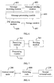
- An embodiment further provides a switching node, which includes a receiving module 701, a sending module 703 and a processing module 705, as shown in FIG. 7 .
- the receiving module 701 is configured to receive the control message which carries the PW label assigned by the terminal node or the switching node, the FEC information and the routing information.
- the routing information carries the identification information of the switching node, and may be included in the TLV parameter in the control message.
- the processing module 705 is configured to process the control message received by the receiving module 701, which includes obtaining identification information of a next hop node on a PW routing according to the routing information in the control message.
- the processing module 705 may include a reading module and a judging module.
- the reading module is configured to read the next identification information of the identification information of the switching node in the routing information carried by the control message.
- the reading module is further configured to read the PW label carried by the control message, and assign a PW label.
- the assigned PW label may be the same as the PW label in the control message or may be different from the PW label in the control message.
- the judging module is configured to judge whether the identification information read by the reading module is null, and if the identification information read by the reading module is null, notify the reading module of reading the value of the TAII field in the FEC information carried by the control message, in which the value of the TAII field could be used as the identification information of the next hop node.
- the reading module is further configured to remove the identification information of the switching node from the routing information after reading the next identification information of the identification information of the switching node in the routing information, so that the identification information of the next switching node is the first identification information in the routing information.
- the sending module 703 is configured to send the control message according to the identification information obtained by the processing module.
- the switching node provided in this embodiment may send the message according to the routing information of the intermediate switching node carried in the control message after receiving the control message for establishing the PW, so that it is unnecessary to set the PW routing table information required for establishing the PW on the switching node and it is also unnecessary to configure mapping relations between each segment of the PW.
- An embodiment of the present invention provides a system for establishing a PW, which includes a first terminal node 200, a second terminal node 220 and a switching node 800, as shown in FIG. 8 .
- the first terminal node 200 is connected to the second terminal node 220 through the switching node 800.
- the first terminal node 200 is configured to construct a control message, where the control message carries a PW label assigned by the first terminal node, first FEC information and first routing information, and send the control message to the switching node 800 according to the first routing information.
- the switching node 800 is configured to receive the control message from the first terminal node 200, process the control message, obtain identification information of a next hop node on a PW route in a direction from the first terminal node 200 to the second terminal node 220, and send a first control message according to the obtained identification information; receive a second control message from the second terminal node 220, process the second control message, obtain identification information of a next hop node on a PW route in a direction from the second terminal node 220 to the first terminal node 200, and send a third control message according to the obtained identification information of the next hop node.
- the switching node 800 obtains the identification information of the next hop node on the PW route in the direction from the first terminal node 200 to the second terminal node 220, which includes: obtaining next identification information of the identification information of the switching node 800 in the control message, using the obtained next identification information as the identification information of the next hop node on the PW route, and when the obtained next identification information is null, obtaining identification information of a target terminal node of the first FEC information in the control message, in which the identification information of the target terminal node is used as the identification information of the next hop node on the PW route.
- the process of obtaining the identification information of the next hop node on the PW route in the direction from the second terminal node 220 to the first terminal node 200 by the switching node is similar to that of obtaining the identification information of the next hop node on the PW route in the direction from the first terminal node 200 to the second terminal node 220, and is not repeated herein.
- the second terminal node 220 is configured to receive the first control message, construct the second control message according to the first control message, and send the second control message to the switching node 800.
- the switching node 800 sends the third control message to the first terminal node 200 according to the second routing information in the received second control message, to establish the PW between the second terminal node and the first terminal node.
- the PW label is assigned.
- the constructing the second control message according to the first control message is performed by two methods as follows:
- the second control message carrying the PW label assigned by the second terminal node 220, the second FEC information and the second routing information is constructed.
- the second terminal node 220 sends the second control message to a corresponding switching node according to the second routing information. For example, the second terminal node 220 sends the second control message to a corresponding switching node according to the first identification information in the second routing information.
- the control message when a control message is constructed by the first terminal node 200, the control message includes the second routing information in addition to carrying the PW label, the first FEC information and the first routing information.
- the second routing information carries the identification information of the switching node on the PW route in the direction from the second terminal node 220 to the first terminal node 200.
- the sequence of the identification information of the switching node carried by the second routing information may be reverse to that of the identification information of the switching node carried by the first routing information. In this way, after the second terminal node 220 receives the control message, it is unnecessary to additionally generate the second routing information, and the second routing information in the control message is directly read.
- the switching node 800 may further read identification information of a next hop node, and remove the identification information of the switching node 800 in the first routing information, to make the identification information of the next switching node on the PW route in the direction from the first terminal node 200 to the second terminal node 220 be the first in the first routing information; in the direction from the second terminal node 220 to the first terminal node 200, the switching node 800 may further remove the identification information of the switching node 800 in the second routing information after reading identification information of a next hop node, to make the identification information of the next switching node on the PW route in the direction from the second terminal node 220 to the first terminal node 200 be the first in the second routing information.
- the identification information of the intermediate switching node on the PW route is carried in the control message sent by the first terminal node.
- the intermediate node may send the control message according to the identification information of the switching node and forward the identification information of the intermediate node on the PW route. In this way, it is unnecessary to additionally configure a PW routing table required for establishing a PW. Meanwhile, by carrying PW routing information in the direction from the second terminal node to the first terminal node in the control message of the first terminal node, the method for constructing the control message by the second terminal node becomes simple.
- the embodiments or part of the embodiments of the present invention may be implemented by using software.
- a corresponding software program may be saved in readable storage media, such as an optical disk, a hard risk, a floppy disk and so on.
Landscapes
- Engineering & Computer Science (AREA)
- Computer Networks & Wireless Communication (AREA)
- Signal Processing (AREA)
- Data Exchanges In Wide-Area Networks (AREA)
Claims (8)
- Endknoten (220), der konfiguriert ist:eine Steuernachricht zu empfangen (520), die ein Pseudoleitungs-Etikett, PW-Etikett, (Etikett 3), FEC-Informationen und Lenkungsinformationen führt, wobei die Lenkungsinformationen Identifikationsinformationen und weitere Identifikationsinformationen umfassen, die Identifikationsinformationen Identifikationsinformationen eines vermittelnden Knotens (215) sind und die weiteren Identifikationsinformationen Identifikationsinformationen eines weiteren vermittelnden Knotens (205) sind, wobei die weiteren Identifikationsinformationen nächste Identifikationsinformationen der Identifikationsinformationen sind;eine weitere Steuernachricht zu konstruieren (530), die ein weiteres PW-Etikett (Etikett 4), weitere FEC-Informationen und die Lenkungsinformationen führt;die weitere Steuernachricht zu dem vermittelnden Knoten (215) zu senden (530).
- Endknoten (220) nach Anspruch 1, der ferner konfiguriert ist, das PW-Etikett (Etikett 3) zu speichern.
- Vermittelnder Knoten (215), der konfiguriert ist:eine Steuernachricht zu empfangen (530), die ein PW-Etikett (Etikett 4), FEC-Informationen und Lenkungsinformationen führt, die Identifikationsinformationen des vermittelnden Knotens (215) und nächste Identifikationsinformationen enthalten, wobei die nächsten Identifikationsinformationen Identifikationsinformationen eines vermittelnden Knotens (205) für den nächsten Sprung des vermittelnden Knotens (215) sind;eine weitere Steuernachricht zu dem vermittelnden Knoten (205) für den nächsten Sprung zu senden (540), wobei die weitere Steuernachricht ein weiteres PW-Etikett (Etikett 5), das durch den vermittelnden Knoten (215) zugewiesen ist, die FEC-Informationen und die Lenkungsinformationen führt, aus dem die Identifikationsinformationen des vermittelnden Knotens (215) entfernt sind.
- Vermittelnder Knoten (215) nach Anspruch 3, der ferner konfiguriert ist, das PW-Etikett (Etikett 4) zu speichern.
- Verfahren zum Aufbauen einer Pseudoleitung, PW, das Folgendes umfasst:Empfangen (520) durch einen Endknoten (220) einer Steuernachricht, die ein Pseudoleitungs-Etikett, PW-Etikett, (Etikett 3), FEC-Informationen und Lenkungsinformationen führt, wobei die Lenkungsinformationen Identifikationsinformationen und weitere Identifikationsinformationen umfassen, die Identifikationsinformationen Identifikationsinformationen eines vermittelnden Knotens (215) sind und die weiteren Identifikationsinformationen Identifikationsinformationen eines weiteren vermittelnden Knotens (205) sind, wobei die weiteren Identifikationsinformationen nächste Identifikationsinformationen der Identifikationsinformationen sind;Konstruieren (530) durch den Endknoten (220) einer weiteren Steuernachricht, die ein weiteres PW-Etikett (Etikett 4), weitere FEC-Informationen und die Lenkungsinformationen führt;Senden (530) durch den Endknoten (220) der weiteren Steuernachricht zu dem vermittelnden Knoten (215).
- Verfahren nach Anspruch 5, das ferner Folgendes umfasst: Speichern durch den Endknoten (220) des PW-Etiketts (Etikett 3).
- Verfahren zum Aufbauen einer Pseudoleitung, PW, das Folgendes umfasst:Empfangen (530) durch einen vermittelnden Knoten (215) einer Steuernachricht, die ein PW-Etikett (Etikett 4), FEC-Informationen und Lenkungsinformationen führt, die Identifikationsinformationen des vermittelnden Knotens (215) und nächste Identifikationsinformationen enthalten, wobei die nächsten Identifikationsinformationen Identifikationsinformationen eines vermittelnden Knotens (205) für den nächsten Sprung des vermittelnden Knotens (215) sind;Senden (540) durch den vermittelnden Knoten (215) einer weiteren Steuernachricht zu dem vermittelnden Knoten (205) für den nächsten Sprung, wobei die weitere Steuernachricht ein weiteres PW-Etikett (Etikett 5), das durch den vermittelnden Knoten (215) zugewiesen ist, die FEC-Informationen und die Lenkungsinformationen führt, aus dem die Identifikationsinformationen des vermittelnden Knotens (215) entfernt sind.
- Verfahren nach Anspruch 7, das ferner Folgendes umfasst:Speichern durch den vermittelnden Knoten (215) des PW-Etiketts (Etikett 4).
Priority Applications (2)
| Application Number | Priority Date | Filing Date | Title |
|---|---|---|---|
| EP14180989.7A EP2822238B1 (de) | 2009-06-29 | 2009-06-29 | Verfahren und Vorrichtung zur Herstellung einer Pseudowire-Verbindung |
| ES14180989.7T ES2611180T3 (es) | 2009-06-29 | 2009-06-29 | Método, dispositivo y sistema para establecer un denominado Pseudo-circuito |
Applications Claiming Priority (3)
| Application Number | Priority Date | Filing Date | Title |
|---|---|---|---|
| EP09846669.1A EP2439888B1 (de) | 2009-06-29 | 2009-06-29 | Vorrichtung und verfahren zur pseudowire-herstellung |
| PCT/CN2009/072504 WO2011000140A1 (zh) | 2009-06-29 | 2009-06-29 | 一种伪线的建立方法、装置和系统 |
| EP14180989.7A EP2822238B1 (de) | 2009-06-29 | 2009-06-29 | Verfahren und Vorrichtung zur Herstellung einer Pseudowire-Verbindung |
Related Parent Applications (2)
| Application Number | Title | Priority Date | Filing Date |
|---|---|---|---|
| EP09846669.1A Division-Into EP2439888B1 (de) | 2009-06-29 | 2009-06-29 | Vorrichtung und verfahren zur pseudowire-herstellung |
| EP09846669.1A Division EP2439888B1 (de) | 2009-06-29 | 2009-06-29 | Vorrichtung und verfahren zur pseudowire-herstellung |
Publications (2)
| Publication Number | Publication Date |
|---|---|
| EP2822238A1 EP2822238A1 (de) | 2015-01-07 |
| EP2822238B1 true EP2822238B1 (de) | 2016-09-21 |
Family
ID=43410441
Family Applications (2)
| Application Number | Title | Priority Date | Filing Date |
|---|---|---|---|
| EP09846669.1A Active EP2439888B1 (de) | 2009-06-29 | 2009-06-29 | Vorrichtung und verfahren zur pseudowire-herstellung |
| EP14180989.7A Active EP2822238B1 (de) | 2009-06-29 | 2009-06-29 | Verfahren und Vorrichtung zur Herstellung einer Pseudowire-Verbindung |
Family Applications Before (1)
| Application Number | Title | Priority Date | Filing Date |
|---|---|---|---|
| EP09846669.1A Active EP2439888B1 (de) | 2009-06-29 | 2009-06-29 | Vorrichtung und verfahren zur pseudowire-herstellung |
Country Status (5)
| Country | Link |
|---|---|
| US (2) | US8964749B2 (de) |
| EP (2) | EP2439888B1 (de) |
| CN (1) | CN102282811B (de) |
| ES (2) | ES2611180T3 (de) |
| WO (1) | WO2011000140A1 (de) |
Families Citing this family (8)
| Publication number | Priority date | Publication date | Assignee | Title |
|---|---|---|---|---|
| CN102195870A (zh) * | 2010-03-01 | 2011-09-21 | 中兴通讯股份有限公司 | 伪线迁移方法及装置 |
| CN102404199B (zh) * | 2011-10-11 | 2014-04-30 | 中兴通讯股份有限公司 | 一种多段伪线的建立及恢复方法、装置和系统 |
| US9042369B2 (en) * | 2013-03-13 | 2015-05-26 | Alcatel Lucent | System and method for reflecting FEC route information |
| WO2015054864A1 (zh) * | 2013-10-17 | 2015-04-23 | 华为技术有限公司 | 二层虚拟专用网络业务的建立方法和设备 |
| US9407541B2 (en) * | 2014-04-24 | 2016-08-02 | International Business Machines Corporation | Propagating a flow policy by control packet in a software defined network (SDN) based network |
| CN104158877A (zh) * | 2014-08-15 | 2014-11-19 | 杭州古北电子科技有限公司 | 远程控制方法、装置及其系统 |
| EP2988451A1 (de) * | 2014-08-22 | 2016-02-24 | Vodafone IP Licensing limited | Verfahren und System zum Abbilden verschiedener Layouts |
| CN106161238A (zh) * | 2015-04-10 | 2016-11-23 | 中兴通讯股份有限公司 | 获取多段伪线路径信息的方法及装置和spe及tpe |
Family Cites Families (10)
| Publication number | Priority date | Publication date | Assignee | Title |
|---|---|---|---|---|
| CN100473069C (zh) | 2004-07-12 | 2009-03-25 | 中兴通讯股份有限公司 | 支持伪线标签反射的二层虚拟专网设备和组网方法 |
| WO2007022640A1 (en) * | 2005-08-26 | 2007-03-01 | Nortel Networks Limited | Method for establishing multi segment pseudowire across domains having different pseudowire signaling protocol |
| CN100555989C (zh) * | 2006-01-20 | 2009-10-28 | 华为技术有限公司 | 一种点到多点伪线的实现方法 |
| US7613188B1 (en) | 2006-04-27 | 2009-11-03 | Alcatel Lucent | Ethernet VLL spoke termination at an IP interface |
| US7532587B2 (en) * | 2006-09-06 | 2009-05-12 | Motorola, Inc. | Method and apparatus for performing anonymous source routing |
| WO2009013582A1 (en) * | 2007-07-20 | 2009-01-29 | Telefonaktiebolaget L M Ericsson (Publ) | System and method for ethernet label distribution |
| CN101355490B (zh) * | 2007-07-25 | 2012-05-23 | 华为技术有限公司 | 消息路由方法、系统和节点设备 |
| US7885259B2 (en) * | 2007-11-30 | 2011-02-08 | Cisco Technology, Inc. | Deterministic multiprotocol label switching (MPLS) labels |
| US7778204B2 (en) * | 2008-07-25 | 2010-08-17 | Alcatel-Lucent Usa Inc. | Automatic maintenance of a distributed source tree (DST) network |
| CN101414979B (zh) * | 2008-11-26 | 2011-07-20 | 北京星网锐捷网络技术有限公司 | 标签分发消息的处理方法及标签交换路由器 |
-
2009
- 2009-06-29 WO PCT/CN2009/072504 patent/WO2011000140A1/zh active Application Filing
- 2009-06-29 ES ES14180989.7T patent/ES2611180T3/es active Active
- 2009-06-29 ES ES09846669.1T patent/ES2531546T3/es active Active
- 2009-06-29 EP EP09846669.1A patent/EP2439888B1/de active Active
- 2009-06-29 CN CN200980158251.XA patent/CN102282811B/zh active Active
- 2009-06-29 EP EP14180989.7A patent/EP2822238B1/de active Active
-
2011
- 2011-12-29 US US13/340,101 patent/US8964749B2/en active Active
-
2015
- 2015-01-23 US US14/604,255 patent/US20150131672A1/en not_active Abandoned
Also Published As
| Publication number | Publication date |
|---|---|
| CN102282811A (zh) | 2011-12-14 |
| US20150131672A1 (en) | 2015-05-14 |
| EP2439888A1 (de) | 2012-04-11 |
| ES2611180T3 (es) | 2017-05-05 |
| EP2439888B1 (de) | 2014-12-10 |
| EP2822238A1 (de) | 2015-01-07 |
| EP2439888A4 (de) | 2012-10-10 |
| US8964749B2 (en) | 2015-02-24 |
| CN102282811B (zh) | 2014-05-21 |
| ES2531546T3 (es) | 2015-03-17 |
| US20120099598A1 (en) | 2012-04-26 |
| WO2011000140A1 (zh) | 2011-01-06 |
Similar Documents
| Publication | Publication Date | Title |
|---|---|---|
| CN109756425B (zh) | 组播转发方法、装置以及bfr | |
| EP2822238B1 (de) | Verfahren und Vorrichtung zur Herstellung einer Pseudowire-Verbindung | |
| CN110445649B (zh) | 用于经由交换结构在边缘设备之间实施连接的方法和装置 | |
| EP1713197B1 (de) | Verfahren zum implementieren der virtuell geleasten leitung | |
| US20180205575A1 (en) | Broadband access | |
| US8416787B2 (en) | Method, system and apparatus for implementing L2VPN between autonomous systems | |
| US9912586B2 (en) | Method, system, and device for establishing pseudo wire | |
| US11563680B2 (en) | Pseudo wire load sharing method and device | |
| RU2528149C1 (ru) | Способ коммутации туннеля и система сервисов многопротокольной коммутации по меткам | |
| CN112511444A (zh) | 一种组播流量传输方法、装置、通信节点及存储介质 | |
| CN112422398B (zh) | 消息传输方法及通信装置 | |
| WO2013139270A1 (zh) | 实现三层虚拟专用网络的方法、设备及系统 | |
| CN103209125B (zh) | 一种标签信息的传输方法和设备 | |
| CN108667729B (zh) | 一种基于mpls的sdn业务隔离及选路的方法和装置 | |
| US10715431B2 (en) | Methods and apparatuses for routing data packets in a network topology | |
| US9154447B2 (en) | System and method for stitching Ethernet networks | |
| WO2023082779A1 (zh) | 报文转发方法、电子设备及存储介质 | |
| CN110572326A (zh) | 转发路径的建立方法、装置、网络设备及系统 | |
| KR101851031B1 (ko) | 오프셋을 사용하는 대역 내 제어 채널을 제공하는 의사회선 | |
| Wu et al. | Research on the application of cross-domain VPN technology based on MPLS BGP | |
| CN112737951B (zh) | 一种公私网混合场景下端到端sr控制方法、系统和可读存储介质 | |
| WO2016127567A1 (zh) | 端到端业务的传输处理方法及装置 |
Legal Events
| Date | Code | Title | Description |
|---|---|---|---|
| PUAI | Public reference made under article 153(3) epc to a published international application that has entered the european phase |
Free format text: ORIGINAL CODE: 0009012 |
|
| 17P | Request for examination filed |
Effective date: 20140814 |
|
| AC | Divisional application: reference to earlier application |
Ref document number: 2439888 Country of ref document: EP Kind code of ref document: P |
|
| AK | Designated contracting states |
Kind code of ref document: A1 Designated state(s): AT BE BG CH CY CZ DE DK EE ES FI FR GB GR HR HU IE IS IT LI LT LU LV MC MK MT NL NO PL PT RO SE SI SK TR |
|
| GRAP | Despatch of communication of intention to grant a patent |
Free format text: ORIGINAL CODE: EPIDOSNIGR1 |
|
| RIC1 | Information provided on ipc code assigned before grant |
Ipc: H04L 12/751 20130101ALN20160301BHEP Ipc: H04L 12/721 20130101AFI20160301BHEP |
|
| INTG | Intention to grant announced |
Effective date: 20160331 |
|
| GRAS | Grant fee paid |
Free format text: ORIGINAL CODE: EPIDOSNIGR3 |
|
| GRAA | (expected) grant |
Free format text: ORIGINAL CODE: 0009210 |
|
| AC | Divisional application: reference to earlier application |
Ref document number: 2439888 Country of ref document: EP Kind code of ref document: P |
|
| AK | Designated contracting states |
Kind code of ref document: B1 Designated state(s): AT BE BG CH CY CZ DE DK EE ES FI FR GB GR HR HU IE IS IT LI LT LU LV MC MK MT NL NO PL PT RO SE SI SK TR |
|
| REG | Reference to a national code |
Ref country code: GB Ref legal event code: FG4D |
|
| REG | Reference to a national code |
Ref country code: CH Ref legal event code: EP |
|
| REG | Reference to a national code |
Ref country code: AT Ref legal event code: REF Ref document number: 831819 Country of ref document: AT Kind code of ref document: T Effective date: 20161015 |
|
| REG | Reference to a national code |
Ref country code: IE Ref legal event code: FG4D |
|
| REG | Reference to a national code |
Ref country code: DE Ref legal event code: R096 Ref document number: 602009041347 Country of ref document: DE |
|
| REG | Reference to a national code |
Ref country code: NL Ref legal event code: FP |
|
| REG | Reference to a national code |
Ref country code: SE Ref legal event code: TRGR |
|
| REG | Reference to a national code |
Ref country code: LT Ref legal event code: MG4D |
|
| PG25 | Lapsed in a contracting state [announced via postgrant information from national office to epo] |
Ref country code: FI Free format text: LAPSE BECAUSE OF FAILURE TO SUBMIT A TRANSLATION OF THE DESCRIPTION OR TO PAY THE FEE WITHIN THE PRESCRIBED TIME-LIMIT Effective date: 20160921 Ref country code: LT Free format text: LAPSE BECAUSE OF FAILURE TO SUBMIT A TRANSLATION OF THE DESCRIPTION OR TO PAY THE FEE WITHIN THE PRESCRIBED TIME-LIMIT Effective date: 20160921 Ref country code: NO Free format text: LAPSE BECAUSE OF FAILURE TO SUBMIT A TRANSLATION OF THE DESCRIPTION OR TO PAY THE FEE WITHIN THE PRESCRIBED TIME-LIMIT Effective date: 20161221 |
|
| REG | Reference to a national code |
Ref country code: AT Ref legal event code: MK05 Ref document number: 831819 Country of ref document: AT Kind code of ref document: T Effective date: 20160921 |
|
| PG25 | Lapsed in a contracting state [announced via postgrant information from national office to epo] |
Ref country code: GR Free format text: LAPSE BECAUSE OF FAILURE TO SUBMIT A TRANSLATION OF THE DESCRIPTION OR TO PAY THE FEE WITHIN THE PRESCRIBED TIME-LIMIT Effective date: 20161222 Ref country code: LV Free format text: LAPSE BECAUSE OF FAILURE TO SUBMIT A TRANSLATION OF THE DESCRIPTION OR TO PAY THE FEE WITHIN THE PRESCRIBED TIME-LIMIT Effective date: 20160921 |
|
| PG25 | Lapsed in a contracting state [announced via postgrant information from national office to epo] |
Ref country code: EE Free format text: LAPSE BECAUSE OF FAILURE TO SUBMIT A TRANSLATION OF THE DESCRIPTION OR TO PAY THE FEE WITHIN THE PRESCRIBED TIME-LIMIT Effective date: 20160921 Ref country code: RO Free format text: LAPSE BECAUSE OF FAILURE TO SUBMIT A TRANSLATION OF THE DESCRIPTION OR TO PAY THE FEE WITHIN THE PRESCRIBED TIME-LIMIT Effective date: 20160921 |
|
| REG | Reference to a national code |
Ref country code: ES Ref legal event code: FG2A Ref document number: 2611180 Country of ref document: ES Kind code of ref document: T3 Effective date: 20170505 |
|
| REG | Reference to a national code |
Ref country code: FR Ref legal event code: PLFP Year of fee payment: 9 |
|
| PG25 | Lapsed in a contracting state [announced via postgrant information from national office to epo] |
Ref country code: PT Free format text: LAPSE BECAUSE OF FAILURE TO SUBMIT A TRANSLATION OF THE DESCRIPTION OR TO PAY THE FEE WITHIN THE PRESCRIBED TIME-LIMIT Effective date: 20170123 Ref country code: BE Free format text: LAPSE BECAUSE OF FAILURE TO SUBMIT A TRANSLATION OF THE DESCRIPTION OR TO PAY THE FEE WITHIN THE PRESCRIBED TIME-LIMIT Effective date: 20160921 Ref country code: CZ Free format text: LAPSE BECAUSE OF FAILURE TO SUBMIT A TRANSLATION OF THE DESCRIPTION OR TO PAY THE FEE WITHIN THE PRESCRIBED TIME-LIMIT Effective date: 20160921 Ref country code: AT Free format text: LAPSE BECAUSE OF FAILURE TO SUBMIT A TRANSLATION OF THE DESCRIPTION OR TO PAY THE FEE WITHIN THE PRESCRIBED TIME-LIMIT Effective date: 20160921 Ref country code: BG Free format text: LAPSE BECAUSE OF FAILURE TO SUBMIT A TRANSLATION OF THE DESCRIPTION OR TO PAY THE FEE WITHIN THE PRESCRIBED TIME-LIMIT Effective date: 20161221 Ref country code: SK Free format text: LAPSE BECAUSE OF FAILURE TO SUBMIT A TRANSLATION OF THE DESCRIPTION OR TO PAY THE FEE WITHIN THE PRESCRIBED TIME-LIMIT Effective date: 20160921 Ref country code: PL Free format text: LAPSE BECAUSE OF FAILURE TO SUBMIT A TRANSLATION OF THE DESCRIPTION OR TO PAY THE FEE WITHIN THE PRESCRIBED TIME-LIMIT Effective date: 20160921 Ref country code: IS Free format text: LAPSE BECAUSE OF FAILURE TO SUBMIT A TRANSLATION OF THE DESCRIPTION OR TO PAY THE FEE WITHIN THE PRESCRIBED TIME-LIMIT Effective date: 20170121 |
|
| REG | Reference to a national code |
Ref country code: DE Ref legal event code: R097 Ref document number: 602009041347 Country of ref document: DE |
|
| PLBE | No opposition filed within time limit |
Free format text: ORIGINAL CODE: 0009261 |
|
| STAA | Information on the status of an ep patent application or granted ep patent |
Free format text: STATUS: NO OPPOSITION FILED WITHIN TIME LIMIT |
|
| PG25 | Lapsed in a contracting state [announced via postgrant information from national office to epo] |
Ref country code: DK Free format text: LAPSE BECAUSE OF FAILURE TO SUBMIT A TRANSLATION OF THE DESCRIPTION OR TO PAY THE FEE WITHIN THE PRESCRIBED TIME-LIMIT Effective date: 20160921 |
|
| 26N | No opposition filed |
Effective date: 20170622 |
|
| PG25 | Lapsed in a contracting state [announced via postgrant information from national office to epo] |
Ref country code: SI Free format text: LAPSE BECAUSE OF FAILURE TO SUBMIT A TRANSLATION OF THE DESCRIPTION OR TO PAY THE FEE WITHIN THE PRESCRIBED TIME-LIMIT Effective date: 20160921 |
|
| PG25 | Lapsed in a contracting state [announced via postgrant information from national office to epo] |
Ref country code: MC Free format text: LAPSE BECAUSE OF FAILURE TO SUBMIT A TRANSLATION OF THE DESCRIPTION OR TO PAY THE FEE WITHIN THE PRESCRIBED TIME-LIMIT Effective date: 20160921 |
|
| REG | Reference to a national code |
Ref country code: CH Ref legal event code: PL |
|
| REG | Reference to a national code |
Ref country code: IE Ref legal event code: MM4A |
|
| PG25 | Lapsed in a contracting state [announced via postgrant information from national office to epo] |
Ref country code: IE Free format text: LAPSE BECAUSE OF NON-PAYMENT OF DUE FEES Effective date: 20170629 Ref country code: LI Free format text: LAPSE BECAUSE OF NON-PAYMENT OF DUE FEES Effective date: 20170630 Ref country code: LU Free format text: LAPSE BECAUSE OF NON-PAYMENT OF DUE FEES Effective date: 20170629 Ref country code: CH Free format text: LAPSE BECAUSE OF NON-PAYMENT OF DUE FEES Effective date: 20170630 |
|
| REG | Reference to a national code |
Ref country code: FR Ref legal event code: PLFP Year of fee payment: 10 |
|
| PG25 | Lapsed in a contracting state [announced via postgrant information from national office to epo] |
Ref country code: MT Free format text: LAPSE BECAUSE OF NON-PAYMENT OF DUE FEES Effective date: 20170629 |
|
| PG25 | Lapsed in a contracting state [announced via postgrant information from national office to epo] |
Ref country code: HU Free format text: LAPSE BECAUSE OF FAILURE TO SUBMIT A TRANSLATION OF THE DESCRIPTION OR TO PAY THE FEE WITHIN THE PRESCRIBED TIME-LIMIT; INVALID AB INITIO Effective date: 20090629 |
|
| PG25 | Lapsed in a contracting state [announced via postgrant information from national office to epo] |
Ref country code: CY Free format text: LAPSE BECAUSE OF FAILURE TO SUBMIT A TRANSLATION OF THE DESCRIPTION OR TO PAY THE FEE WITHIN THE PRESCRIBED TIME-LIMIT Effective date: 20160921 |
|
| PG25 | Lapsed in a contracting state [announced via postgrant information from national office to epo] |
Ref country code: MK Free format text: LAPSE BECAUSE OF FAILURE TO SUBMIT A TRANSLATION OF THE DESCRIPTION OR TO PAY THE FEE WITHIN THE PRESCRIBED TIME-LIMIT Effective date: 20160921 |
|
| PG25 | Lapsed in a contracting state [announced via postgrant information from national office to epo] |
Ref country code: TR Free format text: LAPSE BECAUSE OF FAILURE TO SUBMIT A TRANSLATION OF THE DESCRIPTION OR TO PAY THE FEE WITHIN THE PRESCRIBED TIME-LIMIT Effective date: 20160921 |
|
| PG25 | Lapsed in a contracting state [announced via postgrant information from national office to epo] |
Ref country code: HR Free format text: LAPSE BECAUSE OF FAILURE TO SUBMIT A TRANSLATION OF THE DESCRIPTION OR TO PAY THE FEE WITHIN THE PRESCRIBED TIME-LIMIT Effective date: 20160921 |
|
| REG | Reference to a national code |
Ref country code: DE Ref legal event code: R079 Ref document number: 602009041347 Country of ref document: DE Free format text: PREVIOUS MAIN CLASS: H04L0012721000 Ipc: H04L0045000000 |
|
| REG | Reference to a national code |
Ref country code: FR Ref legal event code: PLFP Year of fee payment: 14 |
|
| P01 | Opt-out of the competence of the unified patent court (upc) registered |
Effective date: 20230515 |
|
| PGFP | Annual fee paid to national office [announced via postgrant information from national office to epo] |
Ref country code: NL Payment date: 20230515 Year of fee payment: 15 Ref country code: IT Payment date: 20230510 Year of fee payment: 15 Ref country code: FR Payment date: 20230510 Year of fee payment: 15 Ref country code: DE Payment date: 20230502 Year of fee payment: 15 |
|
| PGFP | Annual fee paid to national office [announced via postgrant information from national office to epo] |
Ref country code: SE Payment date: 20230510 Year of fee payment: 15 |
|
| PGFP | Annual fee paid to national office [announced via postgrant information from national office to epo] |
Ref country code: GB Payment date: 20230511 Year of fee payment: 15 Ref country code: ES Payment date: 20230711 Year of fee payment: 15 |