EP2822185A1 - Système de radiocommunication distribué - Google Patents
Système de radiocommunication distribué Download PDFInfo
- Publication number
- EP2822185A1 EP2822185A1 EP13174572.1A EP13174572A EP2822185A1 EP 2822185 A1 EP2822185 A1 EP 2822185A1 EP 13174572 A EP13174572 A EP 13174572A EP 2822185 A1 EP2822185 A1 EP 2822185A1
- Authority
- EP
- European Patent Office
- Prior art keywords
- digital
- signals
- radio system
- distributed radio
- communication channel
- Prior art date
- Legal status (The legal status is an assumption and is not a legal conclusion. Google has not performed a legal analysis and makes no representation as to the accuracy of the status listed.)
- Granted
Links
- 238000004891 communication Methods 0.000 claims abstract description 67
- 238000000034 method Methods 0.000 claims abstract description 12
- 230000008569 process Effects 0.000 claims abstract description 6
- 238000012545 processing Methods 0.000 claims description 18
- 238000013459 approach Methods 0.000 description 15
- 238000012937 correction Methods 0.000 description 14
- 230000005540 biological transmission Effects 0.000 description 5
- 230000008901 benefit Effects 0.000 description 2
- 238000000638 solvent extraction Methods 0.000 description 2
- 230000008685 targeting Effects 0.000 description 2
- 238000012546 transfer Methods 0.000 description 2
- 230000006978 adaptation Effects 0.000 description 1
- 230000001419 dependent effect Effects 0.000 description 1
- 230000000694 effects Effects 0.000 description 1
- 238000000605 extraction Methods 0.000 description 1
- 230000002349 favourable effect Effects 0.000 description 1
- 230000006870 function Effects 0.000 description 1
- 238000013507 mapping Methods 0.000 description 1
- 230000008450 motivation Effects 0.000 description 1
- 238000005192 partition Methods 0.000 description 1
- 238000011084 recovery Methods 0.000 description 1
- 230000009467 reduction Effects 0.000 description 1
- 230000001131 transforming effect Effects 0.000 description 1
- 230000002087 whitening effect Effects 0.000 description 1
Images


Classifications
-
- H—ELECTRICITY
- H04—ELECTRIC COMMUNICATION TECHNIQUE
- H04W—WIRELESS COMMUNICATION NETWORKS
- H04W88/00—Devices specially adapted for wireless communication networks, e.g. terminals, base stations or access point devices
- H04W88/08—Access point devices
- H04W88/085—Access point devices with remote components
-
- H—ELECTRICITY
- H04—ELECTRIC COMMUNICATION TECHNIQUE
- H04B—TRANSMISSION
- H04B7/00—Radio transmission systems, i.e. using radiation field
- H04B7/02—Diversity systems; Multi-antenna system, i.e. transmission or reception using multiple antennas
- H04B7/04—Diversity systems; Multi-antenna system, i.e. transmission or reception using multiple antennas using two or more spaced independent antennas
- H04B7/08—Diversity systems; Multi-antenna system, i.e. transmission or reception using multiple antennas using two or more spaced independent antennas at the receiving station
Definitions
- the disclosure relates to a distributed radio system and to a method of operating a radio system.
- Mobile devices such as e.g. receivers, transmitters are more and more used in cars, avionics i.e. in objects that are changing their position in time.
- the communications are normally implemented using wireless communications.
- Each communication device used in these environments has a physical layer.
- the physical layer (PHY) of a wireless communication device usually includes an antenna, a transceiver, and a baseband processing unit.
- the connection between the antenna and the transceiver normally uses a cable that should have good transfer properties for the signals that are either captured by the antenna or have to be sent by the antenna as e.g. small reactance, small resistance.
- These signals are normally modulated at a Radio Frequency (RF), such that the propagation through the air is possible.
- RF Radio Frequency
- the cable properties have to be such that the modulated signals experience hardly any distortion and attenuation, e.g. coaxial cables. Since attenuation scales with the cable length, cable length should be kept to a minimum. Also, for cost reasons, there is a motivation to reduce the use of lengthy cables with stringent transfer characteristics to a minimum.
- a long cable cannot be easily avoided.
- a communication device in a car experiences the challenges of having an antenna at a position that is favorable for reception/transmission conditions e.g. on the roof of the car and a transceiver and baseband processing unit that is placed at the head-unit or in the trunk.
- the trend of using more antennas for Receiving/Transmitting (Rx/Tx) diversity and Multiple Input Multiple Output (MIMO) for improving the communication properties as e.g. robustness, throughput increases the need of lengthy cables.
- RF cables can be avoided when the transceiver is located close to the antenna.
- the baseband processing unit is placed close to the antenna, no expensive RF cables are necessary.
- Fig. 1 A solution that combines scalability with antenna diversity is shown in Fig. 1 .
- the system comprises three receivers 100, 105 and 110, each receiver being connected to a respective antenna 103, 108, 113 for receiving RF signals.
- Each receiver comprises a respective tuner 101, 106, 111 and a respective baseband i.e. DVB-T demodulators 102, 107, 112 for demodulating the signals received from the respective tuners.
- DVB-T demodulators have to be co-located close to each other and therefore lengthy costly cables cannot be avoided between the antennas and tuners.
- Fig. 2 depicts the structure of a signal used on a serial interface targeting the communications among multiple tuner chips and a baseband chip.
- the signal comprises a header, the header including a whitening seed W and synchronizing bits Y.
- the header is followed by a payload comprising the IQ signal and the status bits.
- the system of Fig. 2 shares the same oscillator, and this is not possible in a distributed architecture involving long distances between its multiple components.
- the information shared among the multiple tuner ICs includes a forwarded clock signal.
- the system provides a clock recovery from a whitened data signal included in the transmitted data.
- AGC Automated Gain Control
- a frame for exchanging data between tuner and baseband processing is shown in Fig. 2 and this specific structure can be further used in other configurations.
- a tuner mat comprise typically an input circuitry for adapting to an antenna, the antenna receiving an incoming RF radio signal in a specific frequency range and having a certain modulation as e.g. frequency modulation (FM), amplitude modulation (AM), orthogonal frequency division multiplexing (OFDM), etc.
- the tuner further comprises an amplifier for amplifying the incoming RF signal and for delivering an amplified RF signal.
- the tuner further comprises a local oscillator (LO) which generates a signal of frequency f o which is provided to a mixer.
- LO local oscillator
- the mixer may be active or passive.
- the mixer comprises two mixing sections: one for the in-phase component (I) and another one for Quadrature one (Q).
- a feedback from the mixer to the amplifier is provided in order to keep the overall gain of the amplifier at a desired level, independent of the input frequency. This feedback is usually defined as the Automatic Gain Control (AGC).
- AGC Automatic Gain Control
- the feedback is usually controlled by a controller which is adapting it at appropriate time events as e.g. during the preambles of the packets or during guard intervals.
- the control data from the controller which normally is a digital one, might be transmitted to the next stages in the radio.
- the radio may also have a Received Signal Strength Indication (RSSI) which is an indication of the received RF signal intensity.
- RSSI Received Signal Strength Indication
- the RSSI signal is also available as a digital signal and therefore it can be easily transmitted to other stages.
- the AGC and RSSI can be easily embedded in any serially transmitted information provided that a parallel to serial converter is provided.
- the Analog to digital converter transforms the IF signal into a digital one.
- the ADC acquisition process and output generation is controlled by a clock signal (Ck).
- the ADC could be either a Nyquist e.g. flash, Successive Approximation (SAR) one or Sigma-Delta one (SD).
- the digital signal may be present as a parallel digital word for example as in the flash AD converter case.
- serializer i.e. a parallel to serial converter, is connected to the output of the converter that transforms the parallel digital word into a serial one.
- the ADC may provide directly a serial output.
- a baseband system is considered to receive the digital IF and to demodulate it according to the type of modulation of the signal.
- This demodulation applies specific algorithms that might be implemented either in hardware, software or a combination thereof.
- the demodulation could be made in full i.e. at the output of the baseband system the demodulated useful signal is obtained, or partially i.e. part of the demodulation is carried out in a first subsystem and the remaining part is carried out in a different subsystem, not necessary situated on the same chip or module with the first subsystem.
- diversity gain is considered to be the increase in signal-to-noise ratio due to some diversity scheme, or how much the transmission power can be reduced when a diversity scheme is introduced, without a performance loss.
- Diversity gain is usually expressed in decibel, and sometimes as a power ratio.
- the threshold detector may generate a noiseless digital signal, which is then processed by the baseband unit. If this is done after the full demodulation of the signal then the diversity gain might be lost.
- the proposed solution addresses the problem of long and expensive coax cables since the digital communication channels usually use cheaper cables, e.g., Ethernet cable, serial link cable or even no cables in case of digital wireless communications.
- the digital signals are transmitted serially.
- the communication channel comprises a digital link or an Ethernet link.
- the link may be a serial one.
- the communication channel may also comprise a wireless connection.
- the base-band unit is included in one of the receivers.
- the digital communication channel transmits control signals to the base-band unit for controlling the gain of the tuners and control signals for data selection.
- each analog to digital converters is coupled to a respective digital front end, each digital front end being coupled to the digital communication channel.
- the digital front end may be a passive digital front end.
- correction means adapted to correct imperfections of the analog front end are placed locally, directly after the ADC.
- These means may include provisions for correcting I/Q-mismatch, DC-offset, carrier frequency offset and symbol time offset.
- the values that are used in the correction units are estimated in the baseband processing unit and are then communicated over the digital communication channel.
- the programming of the tuner may be also done over the digital communication channel, e.g. carrier frequency and tuner gain. Since, the ADC maybe oversampled, the signal may be decimated in order to lower the data rate over the digital communication channel.
- the digital front end may be an active digital front end.
- ADC and active digital front end we call this approach "ADC and active digital front end”.
- ADC and active digital front end we call this approach "ADC and active digital front end”.
- ADC and active digital front end we call this approach "ADC and active digital front end”.
- ADC and active digital front end we call this approach "ADC and active digital front end”.
- ADC and active digital front end we call this approach "ADC and active digital front end”.
- the tuner gain control (AGC) algorithm may be situated locally.
- each of the analog to digital converters is coupled to a respective digital front end, each digital front end being further coupled to a respective channel estimation and equalization block, each channel estimation and equalization block being coupled to the digital communication channel.
- This functionality may be extended with equalization and channel estimation. This approach offloads the combining and baseband processing unit with these tasks but the penalty is that channel estimation data is transferred over the digital communication channel in order to be able to facilitate the combining of the signals.
- decision directed equalization in which the outer receiver is incorporated in the decision, the output of the outer receiver may be made available to the channel estimation/equalization algorithms. Depending on the dynamics of the channel conditions, the feedback loop may require short latency.
- the distributed radio system is mounted on a vehicle.
- Fig. 3 depicts distributed radio system. It is shown a distributed radio system comprising a plurality of receivers 1,2,15, each receiver being adapted to receive radio signals and to transmit respective digital signals.
- the system further comprises a digital communication channel 3 coupled to the plurality of receivers 1,2,15 and adapted to receive the digital signals and to transmit the digital signals and a base-band unit 4 coupled to the communication channel 3 and adapted to combine and process the digital signals.
- the digital signals comprise information available in each receiver 1,2,15 of the plurality of receivers for exploiting a diversity gain.
- Each receiver comprises an antenna for receiving a wireless signal, the antenna being coupled to a tuner adapted to down convert the wireless signal and to transmit a down-converted signal to an analog to digital converter (ADC), the ADC transforming the down converted signal into the digital signal to be transmitted to the digital communication channel 3.
- ADC analog to digital converter
- the communication channel may comprise a digital serial link or an Ethernet link or can be a wireless link.
- the concept presented in this application is based on distributing baseband processing over several separately located units i.e. they are not located on the same printed circuit board (PCB) or chip.
- the distribution of baseband processing is done by splitting the baseband processing in such a way that further processing and possibly combining of partly or fully demodulated signals may be done in another unit maintaining the diversity gain.
- the distribution of baseband processing requires communication of the processed baseband signals over a digital communication channel as it is shown in Fig. 3 . Both signal data and control data may be exchanged over the digital communication channel.
- One or more antenna radio signals are processed by a block which shifts the signal from RF to an intermediate frequency (IF) which is suitable to be digitized e.g., IF, near IF, or zero-IF.
- IF intermediate frequency
- the signal is then sampled by an Analog-to-digital converter (ADC).
- ADC Analog-to-digital converter
- the output of the ADC is a digital signal which may be transmitted via the digital communication channel 3 to a baseband unit 4 where the algorithms for combining the multiple digital signals are usually implemented.
- the digital communication channel 3 may be a serial link, an Ethernet link or any other link that includes the required adaptation of the output of the ADC to the selected digital communication channel.
- the proposed solution addresses the problem described in the introductory part since the digital communication channels usually use much cheaper cables, e.g., Ethernet cable, serial link cable or even no cables in case of digital wireless communications, and the output of the ADC conserves all the signal information required for the diversity gains. If the bare output of the ADC is not the preferred choice for transmitting information because of the high data rate and the presence of digital algorithms are used only to control the tuner and the ADC settings, then the distributed radio system shown in Fig.4 may be used.
- Fig. 4 depicts another distributed radio system. It is shown a distributed radio system, wherein the base-band unit is included in a receiver 15 of the plurality of receivers.
- the digital communication channel 3 transmits to the base-band unit 4 control signals for controlling the gain of the tuners and control signals for data selection.
- the digital communication channel 4 may include a forward link and a feedback link transmitting the following data:
- the feedback link comprises control signals for tuner 10, 30, 80 gain control. Tight time constraints may apply for this control in order to enable a fast locking on the incoming radio signals.
- the feedback link also comprises data for channel selection as e.g. carrier frequency or channel number.
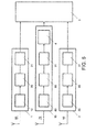
- Fig. 5 depicts a distributed radio system using passive digital front end.
- Digital Front Ends (DFE) 30, 31, 81 are provided for correcting imperfections of the analog front end and are placed locally directly after the ADC.
- the DFE 30, 31, 81 may include means for correcting I/Q-mismatch, DC-offset, carrier frequency offset and symbol time offset.
- the values that are used in the correction units are normally estimated in the baseband unit 4 and are communicated over the digital communication channel 3.
- Programming the tuner 10, 30, 80 may be done over the digital communication channel 3 as e.g. carrier frequency and tuner gain. Since, the ADC may be oversampled, the signal may be decimated in order to lower the data rate over the digital communication channel.
- the data rate maybe higher than Nyquist data rate as in the previous implementation.
- Feedback link is used for tuner programming i.e. comprising data for channel selection as e.g. carrier frequency or channel number and for the tuner gain. It also includes data comprising correction values for I/Q-mismatch, DC-offset, carrier frequency offset and symbol time offset.
- the control algorithms for tuner gain, frequency offset and symbol time offset etc. may be, in this approach, distributed over the baseband unit 4 for estimation process, and blocks close to the antenna for correction purposes.
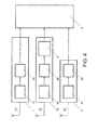
- Fig. 6 depicts a distributed radio system with active digital front end.
- the figure depicts a distributed radio system, wherein each of the analog to digital converters 20, 40, 90 is coupled to a respective digital front end 21',31'81', each digital front being coupled to the digital communication channel 3.
- the forward link and feedback link are used as follows:
- Feedback link is used for tuner programming: data for channel selection, e.g. carrier frequency or channel number.
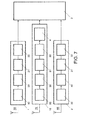
- Fig. 7 depicts another distributed radio system according to the invention.
- each of the analog to digital converters 20,40,90 is coupled to a respective digital front end 21', 31', 81' each digital front end being coupled to a respective channel estimation and equalization block 22,32,82 each channel estimation and equalization block being coupled to the digital communication channel 3.
- the functionality of the previously presented embodiments may be extended with equalization and channel estimation.
- the combining and baseband processing is carried out is this additional block and the respective operations are off-loaded from the baseband unit 4.
- the channel estimation data is transferred over the digital communication channel 3 in order to he able to facilitate the combining of the signals.
- decision directed equalization i.e. the receiver is incorporated in the decision, the output signal of the receiver is available to the channel estimation/equalization algorithms.
- the feedback loop may require short latency.
- Forward link comprises the output of equalizer. Redundant information to help the equalizer maybe removed leaving the signal at a lower than Nyquist data rate. Channel estimation data may be used for combining the signals.
- Feedback link comprises data for channel selection, e.g. carrier frequency or channel number.
- the output of the receiver is provided to the channel estimation and/or equalization algorithms.
- Preferred combining method is phase diversity i.e. equal gain combining, because of FM threshold effect.
- Signals should be aligned in time and phase and therefore the applied tuner gain has to be known and compensated for.
- the AGC control may be closer to the antenna.
- the gain compensated digital samples are tagged with the applied gain.
- the two or more streams should be combined using equal gain combining and the applied tuner gain is used for this purpose.
- the two or more streams are combined in time and their phases should be aligned. Therefore, the streams should be brought to a common clock domain using cross-correlation techniques. The difference in reception path latency should be compensated for.
- DVB Digital Radio/TV using OFDM
- DVB-T Digital Radio/TV using OFDM
- Several splits may be made, resulting in a trade-off between data rates to be exchanged and amount of processing close to the antenna.
- a preferred place for splitting the physical layer is after sub-channel equalization.
- the channel state information per sub-channel is needed and should therefore be exchanged as well.
- Exchange of data is done on base of OFDM symbols and meta-data includes an OFDM symbol number such that the corresponding OFDM symbols are combined.
- IEEE802.11a,g,n,p & ac. (WiFi, ITS) radio These standards use OFDM modulation, so concerning receiver partitioning, the same holds as for Digital Radio/TV using OFDM.
- IEEE802.11p differs in the fact that it is used in highly mobile channel such that preamble based channel estimation does not suffice and one may use decision directed approaches.
- IEEE802.11 is a half-duplex communication standard, such that next to reception, also transmission over multiple antennas (MIMO and Tx diversity) should be solved.
- MIMO and Tx diversity transmission over multiple antennas
- the standard requires that symbol clock and carrier frequency are derived from the same reference.
- the transmission of the several antennas should be time-aligned (ranging over the digital communication channel can be used to estimate the latency between baseband and transceiver).
- the distribution of the local oscillator may be a challenge.
- FMCW frequency modulated continuous wave
- the reception/demodulation is done with the modulated LO that is used for transmission.
- Phase aligned LO distribution over a distributed architecture maybe difficult.
- the signal is a digital signal, e.g. a DAB, HD-radio, China Multimedia Mobile Broadcast (CMMB), Integrated Service Digital Broadcast-Terrestrial (ISDB-T), DVB-T, Wi-Fi IEEE802.11a, etc.
- CMMB China Multimedia Mobile Broadcast
- ISDB-T Integrated Service Digital Broadcast-Terrestrial
- DVB-T Wi-Fi IEEE802.11a
- the combining unit is then capable of properly combining the multiple outputs of the ADCs.
- the reduction of the data rate over the digital channel could be achieved by implementing part of the baseband processing just after the ADC.
- all the functions that drive the RF to baseband block could run locally.
- the time and frequency synchronization of the digital data could run locally, the channel estimation and also pilot extraction.
- the data equalization could run locally, but it would then require a different set of data to be transmitted over the digital communication channel.
- the data should then include the channel state information and time stamps.
Landscapes
- Engineering & Computer Science (AREA)
- Computer Networks & Wireless Communication (AREA)
- Signal Processing (AREA)
- Radio Transmission System (AREA)
Priority Applications (3)
| Application Number | Priority Date | Filing Date | Title |
|---|---|---|---|
| EP13174572.1A EP2822185B1 (fr) | 2013-07-01 | 2013-07-01 | Système de radiocommunication distribué |
| US14/306,676 US9426842B2 (en) | 2013-07-01 | 2014-06-17 | Distributed radio system |
| CN201410290741.8A CN104283600B (zh) | 2013-07-01 | 2014-06-25 | 分布式无线电系统 |
Applications Claiming Priority (1)
| Application Number | Priority Date | Filing Date | Title |
|---|---|---|---|
| EP13174572.1A EP2822185B1 (fr) | 2013-07-01 | 2013-07-01 | Système de radiocommunication distribué |
Publications (2)
| Publication Number | Publication Date |
|---|---|
| EP2822185A1 true EP2822185A1 (fr) | 2015-01-07 |
| EP2822185B1 EP2822185B1 (fr) | 2021-06-16 |
Family
ID=48700426
Family Applications (1)
| Application Number | Title | Priority Date | Filing Date |
|---|---|---|---|
| EP13174572.1A Active EP2822185B1 (fr) | 2013-07-01 | 2013-07-01 | Système de radiocommunication distribué |
Country Status (3)
| Country | Link |
|---|---|
| US (1) | US9426842B2 (fr) |
| EP (1) | EP2822185B1 (fr) |
| CN (1) | CN104283600B (fr) |
Families Citing this family (6)
| Publication number | Priority date | Publication date | Assignee | Title |
|---|---|---|---|---|
| US9584209B2 (en) | 2014-12-31 | 2017-02-28 | Nxp B. V. | Multiple antenna distributed radio system |
| US9900197B1 (en) * | 2016-10-03 | 2018-02-20 | Keyssa Systems, Inc. | BPSK demodulation |
| CN106788887B (zh) * | 2016-12-09 | 2019-09-17 | 天津大学 | 一种基于多路分布式透明硬判决接收的软译码方法 |
| EP3349366B1 (fr) | 2017-01-17 | 2020-10-21 | Nxp B.V. | Procédé et appareil permettant l'attribution dynamique des rôles maître/esclave dans un appareil récepteur à diversité d'antennes réparties |
| DE102017131138A1 (de) * | 2017-12-22 | 2019-06-27 | Te Connectivity Germany Gmbh | Vorrichtung zum Übermitteln von Daten innerhalb eines Fahrzeugs |
| EP4016851B1 (fr) * | 2020-12-18 | 2023-06-21 | Nxp B.V. | Système comprenant de multiples unités |
Citations (6)
| Publication number | Priority date | Publication date | Assignee | Title |
|---|---|---|---|---|
| EP1533918A2 (fr) * | 2003-11-21 | 2005-05-25 | Pioneer Corporation | Récepteur en diversité |
| EP1557962A1 (fr) * | 2002-10-28 | 2005-07-27 | Mitsubishi Denki Kabushiki Kaisha | Dispositif de reception en diversite et procede correspondant |
| EP1909423A1 (fr) * | 2005-07-27 | 2008-04-09 | Pioneer Corporation | Dispositif récepteur |
| WO2008089179A1 (fr) * | 2007-01-19 | 2008-07-24 | Nextwave Broadband Inc. | Émetteur-récepteur équipé de canaux de réception et de transmission ayant une diversité de performances |
| US20110200144A1 (en) * | 2010-02-18 | 2011-08-18 | Bernd Adler | Apparatus and Method for Antenna Diversity Reception |
| WO2012153575A1 (fr) * | 2011-05-10 | 2012-11-15 | 株式会社日立メディアエレクトロニクス | Module de syntonisation et terminal de communication mobile |
Family Cites Families (40)
| Publication number | Priority date | Publication date | Assignee | Title |
|---|---|---|---|---|
| US6349200B1 (en) * | 1997-12-24 | 2002-02-19 | Transcept, Inc. | Monitoring and command system for transceivers used to inter-connect wireless telephones to a broadband network |
| US6882678B2 (en) * | 2000-12-01 | 2005-04-19 | Ning Kong | Method and system for canceling multiple access interference in CDMA wireless communication system |
| US20030181211A1 (en) * | 2002-03-19 | 2003-09-25 | Javad Razavilar | Method and apparatus for dynamic channel selection in wireless modems |
| US7929985B2 (en) * | 2003-05-01 | 2011-04-19 | Telefonaktiebolaget Lm Ericsson (Publ) | Multiple antenna receiver |
| JP2005012648A (ja) * | 2003-06-20 | 2005-01-13 | Toshiba Corp | 無線通信装置及びその送受信回路 |
| US7002470B1 (en) * | 2004-05-03 | 2006-02-21 | Miao George J | Wireless UWB-based space-time sensor networks communications |
| KR100853372B1 (ko) * | 2005-01-18 | 2008-08-22 | 가부시키가이샤 엔티티 도코모 | 이동통신 단말 및 수신 다이버시티 절단방법 |
| US8811273B2 (en) * | 2005-02-22 | 2014-08-19 | Texas Instruments Incorporated | Turbo HSDPA system |
| US9059782B2 (en) * | 2005-06-01 | 2015-06-16 | Broadcom Corporation | Method and system for antenna and radio front-end topologies for a system-on-a-chip (SOC) device that combines bluetooth and IEEE 802.11 b/g WLAN technologies |
| US7573398B2 (en) * | 2005-06-29 | 2009-08-11 | General Electric Company | System and method of communicating signals |
| US8036296B2 (en) * | 2006-09-28 | 2011-10-11 | Broadcom Corporation | Method and system for achieving space and time diversity gain |
| JP4208864B2 (ja) * | 2005-06-30 | 2009-01-14 | 日本テキサス・インスツルメンツ株式会社 | チューナー用半導体装置及びダイバーシティ受信機 |
| JP2007158515A (ja) * | 2005-12-01 | 2007-06-21 | Matsushita Electric Ind Co Ltd | ダイバーシティ受信装置 |
| JP4735312B2 (ja) * | 2006-02-14 | 2011-07-27 | パナソニック株式会社 | 受信装置とこれを用いた電子機器 |
| EP2057753B8 (fr) * | 2006-08-31 | 2015-09-23 | Ericsson Modems SA | Récepteur de communication avec multiplexage du signal reçu, pour recevoir une diversité spatiale |
| US8615276B2 (en) * | 2006-08-31 | 2013-12-24 | Kyocera Corporation | Method for controlling standby operations compatible with a plurality of wireless communication systems and method for performing operations compatible with a plurality of wireless communication systems |
| US20080064356A1 (en) * | 2006-09-07 | 2008-03-13 | Telefonaktiebolaget Lm Ericsson (Publ) | Method of receiving wideband signal |
| US8265326B2 (en) * | 2007-03-14 | 2012-09-11 | Sanjeev Kumar Singh | Hand-held, portable electronic device with retainer port for receiving one or more attachable wireless audiophones for in situ charging |
| JP2008147808A (ja) * | 2006-12-07 | 2008-06-26 | Matsushita Electric Ind Co Ltd | ダイバシティアンテナを用いた高周波信号受信部とこれを用いた高周波信号受信装置 |
| WO2008072451A1 (fr) * | 2006-12-15 | 2008-06-19 | Panasonic Corporation | Dispositif de réception et matériel électronique utilisant le dispositif |
| US7724806B2 (en) * | 2006-12-20 | 2010-05-25 | Motorola, Inc. | Interferer diversity |
| US8862081B2 (en) * | 2007-01-19 | 2014-10-14 | Wi-Lan, Inc. | Transceiver with receive path performance diversity and combiner with jammer detect feedback |
| US8095099B2 (en) * | 2007-03-09 | 2012-01-10 | Bhaskar Patel | Multiple radio receive chain wireless communication devices |
| TW200913598A (en) * | 2007-05-04 | 2009-03-16 | Amicus Wireless Technology Ltd | Automatic gain control circuit for MIMO OFDM receiver |
| US20080287163A1 (en) * | 2007-05-17 | 2008-11-20 | Telefonaktiebolaget Lm Ericsson (Publ), | Method and apparatus for converting between a multi-sector, omni-base station configuration and a multi-sector base station configuration |
| JP2009077023A (ja) * | 2007-09-19 | 2009-04-09 | Sharp Corp | チューナおよびそれを備えたダイバーシティ受信システム |
| US20100197263A1 (en) * | 2009-01-30 | 2010-08-05 | Research In Motion Limited | Method and apparatus for combined multi-carrier reception and receive antenna diversity |
| US8509287B2 (en) * | 2009-10-23 | 2013-08-13 | Broadcom Corporation | Method and system for diversity processing utilizing a programmable interface suppression module |
| US20110130119A1 (en) * | 2009-12-02 | 2011-06-02 | Symbol Technologies, Inc. | Staging a mobile device to an enterprise network securely using voice channel of a wireless wide area network (wwan) |
| JP2011199780A (ja) * | 2010-03-23 | 2011-10-06 | Toshiba Corp | 無線通信装置 |
| US8594256B2 (en) * | 2010-09-14 | 2013-11-26 | Newport Media, Inc. | Low power, multi-chip diversity architecture |
| US8482675B2 (en) * | 2010-09-30 | 2013-07-09 | Newport Media, Inc. | Multi-chip antenna diversity picture-in-picture architecture |
| US8724750B2 (en) * | 2010-12-28 | 2014-05-13 | Qualcomm Incorporated | Adjacent channel rejection of a CCK blocker |
| WO2013013288A1 (fr) * | 2011-07-26 | 2013-01-31 | Research In Motion Limited | Dispositif mobile pour un réseau de relais intelligents |
| US8422540B1 (en) * | 2012-06-21 | 2013-04-16 | CBF Networks, Inc. | Intelligent backhaul radio with zero division duplexing |
| WO2013044951A1 (fr) * | 2011-09-28 | 2013-04-04 | Telefonaktiebolaget L M Ericsson (Publ) | Suivi de phase différentielle en présence d'interférences inconnues |
| WO2013155419A1 (fr) * | 2012-04-12 | 2013-10-17 | Maxlinear, Inc. | Procédé et système de communication wifi utilisant une capture du spectre entier (fsc) |
| US8837650B2 (en) * | 2012-05-29 | 2014-09-16 | Magnolia Broadband Inc. | System and method for discrete gain control in hybrid MIMO RF beamforming for multi layer MIMO base station |
| US20140308899A1 (en) * | 2013-04-10 | 2014-10-16 | Mediatek Inc. | Multi-standards transceiver |
| US20140368743A1 (en) * | 2013-06-14 | 2014-12-18 | Lin Yang | Multiple wi-fi atsc tv antenna receiver |
-
2013
- 2013-07-01 EP EP13174572.1A patent/EP2822185B1/fr active Active
-
2014
- 2014-06-17 US US14/306,676 patent/US9426842B2/en active Active
- 2014-06-25 CN CN201410290741.8A patent/CN104283600B/zh active Active
Patent Citations (6)
| Publication number | Priority date | Publication date | Assignee | Title |
|---|---|---|---|---|
| EP1557962A1 (fr) * | 2002-10-28 | 2005-07-27 | Mitsubishi Denki Kabushiki Kaisha | Dispositif de reception en diversite et procede correspondant |
| EP1533918A2 (fr) * | 2003-11-21 | 2005-05-25 | Pioneer Corporation | Récepteur en diversité |
| EP1909423A1 (fr) * | 2005-07-27 | 2008-04-09 | Pioneer Corporation | Dispositif récepteur |
| WO2008089179A1 (fr) * | 2007-01-19 | 2008-07-24 | Nextwave Broadband Inc. | Émetteur-récepteur équipé de canaux de réception et de transmission ayant une diversité de performances |
| US20110200144A1 (en) * | 2010-02-18 | 2011-08-18 | Bernd Adler | Apparatus and Method for Antenna Diversity Reception |
| WO2012153575A1 (fr) * | 2011-05-10 | 2012-11-15 | 株式会社日立メディアエレクトロニクス | Module de syntonisation et terminal de communication mobile |
Also Published As
| Publication number | Publication date |
|---|---|
| CN104283600A (zh) | 2015-01-14 |
| CN104283600B (zh) | 2017-12-29 |
| US9426842B2 (en) | 2016-08-23 |
| US20150003550A1 (en) | 2015-01-01 |
| EP2822185B1 (fr) | 2021-06-16 |
Similar Documents
| Publication | Publication Date | Title |
|---|---|---|
| US9071326B2 (en) | Distributed radio system | |
| US9426842B2 (en) | Distributed radio system | |
| US20070049348A1 (en) | Diversity transceiver for a wireless local area network | |
| US8811924B2 (en) | Diversity receiver and method performed by a diversity receiver | |
| US9094278B2 (en) | Apparatus, method, and system for transmitting and receiving high-speed data in point-to-point fixed wireless communication | |
| EP1714453B1 (fr) | Transport de donnees de signalisation supplementaires dans un reseau local sans fil a base de ofdm | |
| US20130135986A1 (en) | Microwave Backhaul System Having a Dual Channel Over a Single Interconnect | |
| WO2001091312A2 (fr) | Procede et appareil permettant la mise en oeuvre d'un reseau de communication sans fil a large bande | |
| US20090209201A1 (en) | Apparatus and method of on-channel repeater | |
| US7756473B2 (en) | Apparatus and method of on-channel repeater | |
| EP2477340B1 (fr) | Appareil de communication sans fil et procédé de communication sans fil | |
| US9124471B2 (en) | Systems and methods for transceiver communication | |
| US9219510B2 (en) | Signal receiving system, semiconductor device, and signal receiving method | |
| US7095995B2 (en) | Diversity receiver and orthogonal frequency division multiplexed signal receiving method | |
| US20240195448A1 (en) | DIGITAL PRE-PROCESSING CHIP FOR mmWAVE TRANSCEIVER ARCHITECTURES | |
| US10673480B2 (en) | Device for transmitting and receiving mobile radio signals by means of a stationary antenna | |
| EP2803146B1 (fr) | Systèmes et procédés pour une haute capacité améliorée dans des systèmes de communication sans fil | |
| KR20100058075A (ko) | 무선 랜 공유 장치 | |
| KR20150062670A (ko) | 송수신기 및 송수신기의 rf 회로 신호 왜곡 보완 방법 |
Legal Events
| Date | Code | Title | Description |
|---|---|---|---|
| PUAI | Public reference made under article 153(3) epc to a published international application that has entered the european phase |
Free format text: ORIGINAL CODE: 0009012 |
|
| 17P | Request for examination filed |
Effective date: 20140326 |
|
| AK | Designated contracting states |
Kind code of ref document: A1 Designated state(s): AL AT BE BG CH CY CZ DE DK EE ES FI FR GB GR HR HU IE IS IT LI LT LU LV MC MK MT NL NO PL PT RO RS SE SI SK SM TR |
|
| AX | Request for extension of the european patent |
Extension state: BA ME |
|
| RBV | Designated contracting states (corrected) |
Designated state(s): AL AT BE BG CH CY CZ DE DK EE ES FI FR GB GR HR HU IE IS IT LI LT LU LV MC MK MT NL NO PL PT RO RS SE SI SK SM TR |
|
| STAA | Information on the status of an ep patent application or granted ep patent |
Free format text: STATUS: EXAMINATION IS IN PROGRESS |
|
| 17Q | First examination report despatched |
Effective date: 20180719 |
|
| RIC1 | Information provided on ipc code assigned before grant |
Ipc: H04B 7/08 20060101ALN20200320BHEP Ipc: H04W 88/08 20090101AFI20200320BHEP |
|
| GRAP | Despatch of communication of intention to grant a patent |
Free format text: ORIGINAL CODE: EPIDOSNIGR1 |
|
| STAA | Information on the status of an ep patent application or granted ep patent |
Free format text: STATUS: GRANT OF PATENT IS INTENDED |
|
| RIC1 | Information provided on ipc code assigned before grant |
Ipc: H04W 88/08 20090101AFI20201116BHEP Ipc: H04B 7/08 20060101ALN20201116BHEP |
|
| INTG | Intention to grant announced |
Effective date: 20201207 |
|
| GRAJ | Information related to disapproval of communication of intention to grant by the applicant or resumption of examination proceedings by the epo deleted |
Free format text: ORIGINAL CODE: EPIDOSDIGR1 |
|
| STAA | Information on the status of an ep patent application or granted ep patent |
Free format text: STATUS: EXAMINATION IS IN PROGRESS |
|
| REG | Reference to a national code |
Ref country code: DE Ref legal event code: R079 Ref document number: 602013077927 Country of ref document: DE Free format text: PREVIOUS MAIN CLASS: H04B0001060000 Ipc: H04W0088080000 |
|
| GRAP | Despatch of communication of intention to grant a patent |
Free format text: ORIGINAL CODE: EPIDOSNIGR1 |
|
| STAA | Information on the status of an ep patent application or granted ep patent |
Free format text: STATUS: GRANT OF PATENT IS INTENDED |
|
| INTC | Intention to grant announced (deleted) | ||
| GRAS | Grant fee paid |
Free format text: ORIGINAL CODE: EPIDOSNIGR3 |
|
| GRAA | (expected) grant |
Free format text: ORIGINAL CODE: 0009210 |
|
| STAA | Information on the status of an ep patent application or granted ep patent |
Free format text: STATUS: THE PATENT HAS BEEN GRANTED |
|
| RIC1 | Information provided on ipc code assigned before grant |
Ipc: H04W 88/08 20090101AFI20210412BHEP Ipc: H04B 7/08 20060101ALN20210412BHEP |
|
| INTG | Intention to grant announced |
Effective date: 20210429 |
|
| RIC1 | Information provided on ipc code assigned before grant |
Ipc: H04W 88/08 20090101AFI20210420BHEP Ipc: H04B 7/08 20060101ALN20210420BHEP |
|
| AK | Designated contracting states |
Kind code of ref document: B1 Designated state(s): AL AT BE BG CH CY CZ DE DK EE ES FI FR GB GR HR HU IE IS IT LI LT LU LV MC MK MT NL NO PL PT RO RS SE SI SK SM TR |
|
| REG | Reference to a national code |
Ref country code: GB Ref legal event code: FG4D |
|
| REG | Reference to a national code |
Ref country code: CH Ref legal event code: EP |
|
| REG | Reference to a national code |
Ref country code: DE Ref legal event code: R096 Ref document number: 602013077927 Country of ref document: DE |
|
| REG | Reference to a national code |
Ref country code: AT Ref legal event code: REF Ref document number: 1403409 Country of ref document: AT Kind code of ref document: T Effective date: 20210715 |
|
| REG | Reference to a national code |
Ref country code: IE Ref legal event code: FG4D |
|
| REG | Reference to a national code |
Ref country code: LT Ref legal event code: MG9D |
|
| PG25 | Lapsed in a contracting state [announced via postgrant information from national office to epo] |
Ref country code: HR Free format text: LAPSE BECAUSE OF FAILURE TO SUBMIT A TRANSLATION OF THE DESCRIPTION OR TO PAY THE FEE WITHIN THE PRESCRIBED TIME-LIMIT Effective date: 20210616 Ref country code: BG Free format text: LAPSE BECAUSE OF FAILURE TO SUBMIT A TRANSLATION OF THE DESCRIPTION OR TO PAY THE FEE WITHIN THE PRESCRIBED TIME-LIMIT Effective date: 20210916 Ref country code: FI Free format text: LAPSE BECAUSE OF FAILURE TO SUBMIT A TRANSLATION OF THE DESCRIPTION OR TO PAY THE FEE WITHIN THE PRESCRIBED TIME-LIMIT Effective date: 20210616 Ref country code: LT Free format text: LAPSE BECAUSE OF FAILURE TO SUBMIT A TRANSLATION OF THE DESCRIPTION OR TO PAY THE FEE WITHIN THE PRESCRIBED TIME-LIMIT Effective date: 20210616 |
|
| REG | Reference to a national code |
Ref country code: AT Ref legal event code: MK05 Ref document number: 1403409 Country of ref document: AT Kind code of ref document: T Effective date: 20210616 |
|
| REG | Reference to a national code |
Ref country code: NL Ref legal event code: MP Effective date: 20210616 |
|
| PG25 | Lapsed in a contracting state [announced via postgrant information from national office to epo] |
Ref country code: NO Free format text: LAPSE BECAUSE OF FAILURE TO SUBMIT A TRANSLATION OF THE DESCRIPTION OR TO PAY THE FEE WITHIN THE PRESCRIBED TIME-LIMIT Effective date: 20210916 Ref country code: GR Free format text: LAPSE BECAUSE OF FAILURE TO SUBMIT A TRANSLATION OF THE DESCRIPTION OR TO PAY THE FEE WITHIN THE PRESCRIBED TIME-LIMIT Effective date: 20210917 Ref country code: LV Free format text: LAPSE BECAUSE OF FAILURE TO SUBMIT A TRANSLATION OF THE DESCRIPTION OR TO PAY THE FEE WITHIN THE PRESCRIBED TIME-LIMIT Effective date: 20210616 Ref country code: RS Free format text: LAPSE BECAUSE OF FAILURE TO SUBMIT A TRANSLATION OF THE DESCRIPTION OR TO PAY THE FEE WITHIN THE PRESCRIBED TIME-LIMIT Effective date: 20210616 Ref country code: SE Free format text: LAPSE BECAUSE OF FAILURE TO SUBMIT A TRANSLATION OF THE DESCRIPTION OR TO PAY THE FEE WITHIN THE PRESCRIBED TIME-LIMIT Effective date: 20210616 |
|
| PG25 | Lapsed in a contracting state [announced via postgrant information from national office to epo] |
Ref country code: EE Free format text: LAPSE BECAUSE OF FAILURE TO SUBMIT A TRANSLATION OF THE DESCRIPTION OR TO PAY THE FEE WITHIN THE PRESCRIBED TIME-LIMIT Effective date: 20210616 Ref country code: CZ Free format text: LAPSE BECAUSE OF FAILURE TO SUBMIT A TRANSLATION OF THE DESCRIPTION OR TO PAY THE FEE WITHIN THE PRESCRIBED TIME-LIMIT Effective date: 20210616 Ref country code: SM Free format text: LAPSE BECAUSE OF FAILURE TO SUBMIT A TRANSLATION OF THE DESCRIPTION OR TO PAY THE FEE WITHIN THE PRESCRIBED TIME-LIMIT Effective date: 20210616 Ref country code: SK Free format text: LAPSE BECAUSE OF FAILURE TO SUBMIT A TRANSLATION OF THE DESCRIPTION OR TO PAY THE FEE WITHIN THE PRESCRIBED TIME-LIMIT Effective date: 20210616 Ref country code: NL Free format text: LAPSE BECAUSE OF FAILURE TO SUBMIT A TRANSLATION OF THE DESCRIPTION OR TO PAY THE FEE WITHIN THE PRESCRIBED TIME-LIMIT Effective date: 20210616 Ref country code: PT Free format text: LAPSE BECAUSE OF FAILURE TO SUBMIT A TRANSLATION OF THE DESCRIPTION OR TO PAY THE FEE WITHIN THE PRESCRIBED TIME-LIMIT Effective date: 20211018 Ref country code: RO Free format text: LAPSE BECAUSE OF FAILURE TO SUBMIT A TRANSLATION OF THE DESCRIPTION OR TO PAY THE FEE WITHIN THE PRESCRIBED TIME-LIMIT Effective date: 20210616 Ref country code: ES Free format text: LAPSE BECAUSE OF FAILURE TO SUBMIT A TRANSLATION OF THE DESCRIPTION OR TO PAY THE FEE WITHIN THE PRESCRIBED TIME-LIMIT Effective date: 20210616 Ref country code: AT Free format text: LAPSE BECAUSE OF FAILURE TO SUBMIT A TRANSLATION OF THE DESCRIPTION OR TO PAY THE FEE WITHIN THE PRESCRIBED TIME-LIMIT Effective date: 20210616 |
|
| PG25 | Lapsed in a contracting state [announced via postgrant information from national office to epo] |
Ref country code: PL Free format text: LAPSE BECAUSE OF FAILURE TO SUBMIT A TRANSLATION OF THE DESCRIPTION OR TO PAY THE FEE WITHIN THE PRESCRIBED TIME-LIMIT Effective date: 20210616 |
|
| REG | Reference to a national code |
Ref country code: CH Ref legal event code: PL |
|
| REG | Reference to a national code |
Ref country code: DE Ref legal event code: R097 Ref document number: 602013077927 Country of ref document: DE |
|
| PG25 | Lapsed in a contracting state [announced via postgrant information from national office to epo] |
Ref country code: MC Free format text: LAPSE BECAUSE OF FAILURE TO SUBMIT A TRANSLATION OF THE DESCRIPTION OR TO PAY THE FEE WITHIN THE PRESCRIBED TIME-LIMIT Effective date: 20210616 |
|
| REG | Reference to a national code |
Ref country code: BE Ref legal event code: MM Effective date: 20210731 |
|
| PLBE | No opposition filed within time limit |
Free format text: ORIGINAL CODE: 0009261 |
|
| STAA | Information on the status of an ep patent application or granted ep patent |
Free format text: STATUS: NO OPPOSITION FILED WITHIN TIME LIMIT |
|
| PG25 | Lapsed in a contracting state [announced via postgrant information from national office to epo] |
Ref country code: LI Free format text: LAPSE BECAUSE OF NON-PAYMENT OF DUE FEES Effective date: 20210731 Ref country code: DK Free format text: LAPSE BECAUSE OF FAILURE TO SUBMIT A TRANSLATION OF THE DESCRIPTION OR TO PAY THE FEE WITHIN THE PRESCRIBED TIME-LIMIT Effective date: 20210616 Ref country code: CH Free format text: LAPSE BECAUSE OF NON-PAYMENT OF DUE FEES Effective date: 20210731 |
|
| 26N | No opposition filed |
Effective date: 20220317 |
|
| GBPC | Gb: european patent ceased through non-payment of renewal fee |
Effective date: 20210916 |
|
| PG25 | Lapsed in a contracting state [announced via postgrant information from national office to epo] |
Ref country code: LU Free format text: LAPSE BECAUSE OF NON-PAYMENT OF DUE FEES Effective date: 20210701 Ref country code: AL Free format text: LAPSE BECAUSE OF FAILURE TO SUBMIT A TRANSLATION OF THE DESCRIPTION OR TO PAY THE FEE WITHIN THE PRESCRIBED TIME-LIMIT Effective date: 20210616 |
|
| PG25 | Lapsed in a contracting state [announced via postgrant information from national office to epo] |
Ref country code: IT Free format text: LAPSE BECAUSE OF FAILURE TO SUBMIT A TRANSLATION OF THE DESCRIPTION OR TO PAY THE FEE WITHIN THE PRESCRIBED TIME-LIMIT Effective date: 20210616 Ref country code: IE Free format text: LAPSE BECAUSE OF NON-PAYMENT OF DUE FEES Effective date: 20210701 Ref country code: GB Free format text: LAPSE BECAUSE OF NON-PAYMENT OF DUE FEES Effective date: 20210916 Ref country code: BE Free format text: LAPSE BECAUSE OF NON-PAYMENT OF DUE FEES Effective date: 20210731 |
|
| PG25 | Lapsed in a contracting state [announced via postgrant information from national office to epo] |
Ref country code: HU Free format text: LAPSE BECAUSE OF FAILURE TO SUBMIT A TRANSLATION OF THE DESCRIPTION OR TO PAY THE FEE WITHIN THE PRESCRIBED TIME-LIMIT; INVALID AB INITIO Effective date: 20130701 |
|
| PG25 | Lapsed in a contracting state [announced via postgrant information from national office to epo] |
Ref country code: CY Free format text: LAPSE BECAUSE OF FAILURE TO SUBMIT A TRANSLATION OF THE DESCRIPTION OR TO PAY THE FEE WITHIN THE PRESCRIBED TIME-LIMIT Effective date: 20210616 |
|
| P01 | Opt-out of the competence of the unified patent court (upc) registered |
Effective date: 20230725 |
|
| PGFP | Annual fee paid to national office [announced via postgrant information from national office to epo] |
Ref country code: DE Payment date: 20230620 Year of fee payment: 11 |
|
| PG25 | Lapsed in a contracting state [announced via postgrant information from national office to epo] |
Ref country code: MK Free format text: LAPSE BECAUSE OF FAILURE TO SUBMIT A TRANSLATION OF THE DESCRIPTION OR TO PAY THE FEE WITHIN THE PRESCRIBED TIME-LIMIT Effective date: 20210616 |
|
| PGFP | Annual fee paid to national office [announced via postgrant information from national office to epo] |
Ref country code: FR Payment date: 20240619 Year of fee payment: 12 |