EP2822176A2 - Vector control apparatus of induction motor - Google Patents
Vector control apparatus of induction motor Download PDFInfo
- Publication number
- EP2822176A2 EP2822176A2 EP14174090.2A EP14174090A EP2822176A2 EP 2822176 A2 EP2822176 A2 EP 2822176A2 EP 14174090 A EP14174090 A EP 14174090A EP 2822176 A2 EP2822176 A2 EP 2822176A2
- Authority
- EP
- European Patent Office
- Prior art keywords
- velocity
- command
- value
- pid
- tension
- Prior art date
- Legal status (The legal status is an assumption and is not a legal conclusion. Google has not performed a legal analysis and makes no representation as to the accuracy of the status listed.)
- Granted
Links
Images


Classifications
-
- H—ELECTRICITY
- H02—GENERATION; CONVERSION OR DISTRIBUTION OF ELECTRIC POWER
- H02P—CONTROL OR REGULATION OF ELECTRIC MOTORS, ELECTRIC GENERATORS OR DYNAMO-ELECTRIC CONVERTERS; CONTROLLING TRANSFORMERS, REACTORS OR CHOKE COILS
- H02P21/00—Arrangements or methods for the control of electric machines by vector control, e.g. by control of field orientation
- H02P21/14—Estimation or adaptation of machine parameters, e.g. flux, current or voltage
-
- H—ELECTRICITY
- H02—GENERATION; CONVERSION OR DISTRIBUTION OF ELECTRIC POWER
- H02P—CONTROL OR REGULATION OF ELECTRIC MOTORS, ELECTRIC GENERATORS OR DYNAMO-ELECTRIC CONVERTERS; CONTROLLING TRANSFORMERS, REACTORS OR CHOKE COILS
- H02P21/00—Arrangements or methods for the control of electric machines by vector control, e.g. by control of field orientation
- H02P21/22—Current control, e.g. using a current control loop
-
- H—ELECTRICITY
- H02—GENERATION; CONVERSION OR DISTRIBUTION OF ELECTRIC POWER
- H02P—CONTROL OR REGULATION OF ELECTRIC MOTORS, ELECTRIC GENERATORS OR DYNAMO-ELECTRIC CONVERTERS; CONTROLLING TRANSFORMERS, REACTORS OR CHOKE COILS
- H02P21/00—Arrangements or methods for the control of electric machines by vector control, e.g. by control of field orientation
- H02P21/50—Vector control arrangements or methods not otherwise provided for in H02P21/00- H02P21/36
Definitions
- the teachings in accordance with the exemplary embodiments of this present disclosure generally relate to a vector control apparatus of induction motor, and more particularly to a vector control apparatus of induction motor configured to be operated by a winder control algorithm free from diameter computation.
- rollers simultaneously drive rollers on continuous product manufacturing lines such as steel, paper, textile and film manufacturing industries.
- the purpose of controlling rollers in the continuous processing is to constantly maintain a line speed of line and to simultaneously maintain a tension on materials.
- materials may be ruptured, and when an excessively low tension is generated, meandering may be generated.
- a high level controller in the continuous processing system calculates a diameter of material and motor command torque in response to linear velocity command, and instructs an inverter, the inverter drives the motor in response to the command torque.
- an accurate control of a motor by an inverter may determine a stable operation of rollers in the continuous product manufacturing lines.
- An exemplary embodiment of the present disclosure is to provide a vector control apparatus of induction motor configured to be operated by a winder control algorithm free from diameter computation, whereby operational reliability can be enhanced.
- a vector control apparatus configured to control tension of a motor free from diameter computation, the vector control apparatus comprising:
- the tension velocity generator may include a comparator configured to compare a PID command inputted from the outside with a PID feedback value and to output an error of PID value in response to the comparison, a PID controller configured to output a PID output for compensating the error of the PID value outputted from the comparator, a compensation gain computing element configured to compute a compensation gain corresponding to a diameter value of the motor by determining the PID output, a multiplier configured to multiply a command velocity provided from outside for control of the motor by the compensation gain, and an adder configured to add a command velocity outputted from the multiplier and a PID output outputted from the PID controller.
- a comparator configured to compare a PID command inputted from the outside with a PID feedback value and to output an error of PID value in response to the comparison
- a PID controller configured to output a PID output for compensating the error of the PID value outputted from the comparator
- a compensation gain computing element configured to compute a compensation gain corresponding to a diameter value
- the vector control apparatus of induction motor has a first advantageous effect in that compensation gain is computed by using an output value of PID controller by the compensation gain computing element.
- the second advantageous effect is to realize a diameter computation-free winder velocity control algorithm for constantly maintaining a tension using no diameter computation by compensating, without diameter computation, a linear velocity for maintaining a tension, aside from a PID controller by applying a computed compensation gain to a command linear velocity.
- the present disclosure relates to a diameter computation-free winder velocity control algorithm capable of performing a tension control with no material rupture and meandering by constantly maintaining a tension of an inverter through computation of command torque of a motor in response to actual diameter change of material using no diameter computation when a linear velocity and a reference tension are instructed to the inverter in a continuous processing line.
- An inverter drives a motor by performing a motor command velocity and tension control in response to a material diameter.
- the inverter uses a diameter computation algorithm and controls the motor command velocity and tension control using a diameter obtained therefrom, where a tension PID controller compensates an instantaneous tension.
- the present disclosure is configured to improve an inverter function by proposing a new diameter computation-free velocity control winder algorithm using no diameter computation of material.
- FIG. 1 is a block diagram illustrating a vector control apparatus of induction motor according to an exemplary embodiment of the present disclosure.
- the vector control apparatus of induction motor includes a tension velocity generator (100) and a vector controller (200).
- the tension velocity generator (100) includes a comparator (10), a PID controller (11), a diameter computing element (12), an adder (1) and a command velocity computing element (2).
- the comparator (10) compares a command velocity inputted from outside, a PID command inputted from outside and an actual PID feedback value (Fbk), and outputs an error in response to the comparison thereof.
- the PID controller (11) outputs a PID output for compensating an error of the PID value outputted from the comparator (10).
- the adder (1) adds a command velocity inputted from outside to a PID output outputted from the PID controller (11).
- the diameter computing element (12) computes a diameter using a command linear velocity, a maximum velocity (RPMmax) and a minimum diameter (Dmin) of a motor at a command linear velocity and a maximum linear velocity command, and a rotation velocity detected by a velocity detector (19).
- the command velocity computing element (2) computes a command velocity by applying a diameter value obtained from the diameter computing element (12) to the velocity outputted from the adder (1).
- the vector controller (200) includes a comparator (3), a velocity controller (4), a comparator (5), a current controller (6), a voltage coordinate converter (7), a 3-phase voltage converter (8), a vector control inverter (9), a comparator (13), a slip computing element (14), an adder (15), an integrator (16), a current coordinate converter (17), and a current converter (18).
- the comparator (3) compares a rotation velocity ( ⁇ r ) detected by the velocity detector (19) with a command value ⁇ r * outputted by the command velocity computing element (2) and outputs an error in response to the comparison thereof.
- the comparator (5) compares a torque current command value i qs e * for compensating an error caused by velocity outputted from the comparator (3) with an actual torque current i qs e and outputs the comparison.
- the comparator (13) compares a flux current command value i ds e * inputted from outside with an actually outputted flux current i ds e and outputs the comparison.
- the current controller (6) generates a flux voltage command value v ds e * and a torque voltage command value v qs e * through a torque current and a flux current outputted after being compared by the comparator (5) and the comparator (13).
- the voltage coordinator converter (7) converts a flux voltage command value v ds e * and a torque voltage command value v qs e * at a rotation coordinate outputted from the current controller (6) from a rotation coordinate to a stationary coordinate, and outputs the same.
- the 3-phase voltage converter (8) converts a flux voltage command value v ds s * and a torque voltage command value v qs s * at a stationary coordinate outputted from the voltage coordinate converter (7) to 3-phase voltages ( v as , v bs , v cs ) of stationary coordinate and outputs the same.
- the vector control inverter (9) applies the 3-phase voltage ( v as , v bs , v cs ) of 3-phase voltage converter (8) to an induction motor (20) and rotates the induction motor.
- a 2-pase current converter (18) receives 3-phase currents (i as , i bs , i cs ) detected during rotation of the induction motor (20) and outputs currents i ds s , i qs s converted to d axis and q axis of the stationary coordinate.
- the current coordinate converter (17) converts currents i ds s , i qs s of stationary coordinate outputted from the 2-phase current converter (18) to an actual flux current i d ⁇ s e and a torque current i q ⁇ s e of rotation coordinate and outputs the same.
- the slip computing element (14) uses the torque current command value i q ⁇ s e * outputted from the velocity controller (4), a flux current command value i d ⁇ s e * inputted from outside and an induction motor rotor time constant ( T r ) to compute a slip frequency ( ⁇ sl ).
- the adder (15) adds the slip frequency ( ⁇ sl ) computed by the slip computing element (14) and a velocity ( ⁇ r ) detected by the velocity detector (19).
- the integrator (16) integrates a value added by the adder (15) to set a position ( ⁇ ) of rotor flux used by the voltage coordinate converter (7) and the current coordinate converter (17).
- the velocity detector (19) detects the rotation velocity ( ⁇ r ) and outputs the detected velocity.
- a command velocity inputted from outside, a PID command inputted from outside and an actual PID feedback value (Fbk) are compared, and a velocity is outputted to the adder (1) in which an output of the PID controller (11) is added that outputs a PID output for compensating an output error of the comparator (10) outputting an error in response to the comparison.
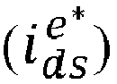
- a flux current command value i d ⁇ s e * inputted from outside is inputted to the non-inversion terminal (+) of the comparator (13).
- the 3-phase currents ( i as , i bs , i cs ) detected by the induction motor (20) at the time of rotation are outputted as stationary coordinate 2-phase currents i d ⁇ s s ⁇ i q ⁇ s s by the 2-phase current converter (18).
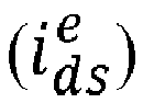
- the stationary coordinate 2-phase currents i d ⁇ s s ⁇ i q ⁇ s s outputted by the 2-phase current converter (18) are inputted to the current coordinate converter(17) and outputted as an actual flux current i d ⁇ s e of the rotation coordinate and torque current i q ⁇ s e . Furthermore, the flux current i d ⁇ s e outputted from the current coordinate converter (17) is outputted to an inversion terminal (-) of the comparator (13).
- the comparator (13) obtains an error between the flux current command value i d ⁇ s e * inputted from outside and an actual flux current i d ⁇ s e outputted from the current coordinate converter (17) and outputs the error to the current controller (6). Furthermore, the comparator (5) receives the torque current command value i q ⁇ s e * outputted from the velocity controller (4) at the non-inversion terminal (+) and receives the Actual torque current i q ⁇ s e outputted from the current coordinate converter (17) at the inversion terminal (-) to obtain an error between the two values, and the obtained error is outputted to the current controller (6).
- the current controller (6) receiving, as input, the torque current outputted from the comparator and flux current outputted from the comparator outputs to the voltage coordinate converter (7), outputs the flux voltage command value v d ⁇ s e * and the torque voltage command value v q ⁇ s e * to the voltage coordinate converter (7) through control.
- the voltage coordinate converter (7) receives the flux voltage command value v d ⁇ s s * and the torque voltage command value v q ⁇ s s * , converts to 3-phase voltages ( v as , v bs , v cs ) through the 3-phase voltage converter (8), and provide the same to the vector control inverter (9), where the vector control inverter (9) applies the 3-phase voltages ( v as , v bs , v cs ) to the induction motor (20).
- the induction motor (20) is rotated, and at this time, actual flux current i d ⁇ s e and torque current i q ⁇ s e converted from actual rotation coordinate to d axis and q axis through the current coordinate converter (18) and the 2-phase current converter (17) are generated, and the flux current i d ⁇ s e among the currents thus generated is outputted to the comparator (13), and the torque current i q ⁇ s e is outputted to the comparator.
- the slip computing element (14) computes a slip frequency ( ⁇ sl ) using the torque current command value i q ⁇ s e * inputted from outside, flux current command value i d ⁇ s e * inputted from outside and an induction motor rotor time constant, and the slip frequency ( ⁇ sl ) is outputted to a terminal at one side of the adder (15).
- the adder (15) adds a velocity ( ⁇ r ) outputted from the velocity detector (19) and the slip frequency ( ⁇ sl ) outputted from the slip computing element (14) and outputs the addition to the integrator (16), where the integrator (16) outputs a value integrated to a value outputted from the adder (15), i.e., a position ( ⁇ ) of rotor flux to the voltage coordinate converter (7) and the current coordinate converter (17).
- the voltage coordinate converter (7) and the current coordinate converter (17) controls a coordinate conversion in response to the position ( ⁇ ) of the rotor flux inputted from the integrator (16), and subsequent operation is as mentioned before.
- the vector control apparatus thus described outputs a command velocity by applying basically computed diameter value for obtaining a torque command for maintaining a tension.
- a user in order to compute a diameter, a user must learn an accurate maximum linear velocity, bobbin diameter and gear ratio of winder system.
- various diameters of bobbin are actually used and an accurate measurement value for diameter computation cannot be obtained, where, if no computation function is not used, the torque command changed value in response to actual diameter change is compensated only by a PID controller. In this case, a quick control in response to the instantaneous change cannot be performed due to saturation of the PID controller.
- a need is proposed to a control technique capable of coping with an actual diameter change without saturation of output value of the PID controller.
- the vector control apparatus is configured such that when an upper level controller instructs a linear velocity and tension to an inverter, a command linear velocity is computed by applying, to the applied linear velocity, a compensation gain (Comp Gain) substitutable of diameter value, and a command velocity is computed for constantly maintaining a tension by adding a computed PID controller output value to the command linear velocity using the tension measurement value obtained through the applied tension command and tension sensor.
- a compensation gain Comp Gain
- the PID controller output value is used for compensation gain computation lest saturation be generated.
- FIG. 2 is a block diagram illustrating a diameter computation-free velocity control winder algorithm according to another exemplary embodiment of the present disclosure
- FIG. 3 is a block diagram illustrating a compensation gain computing element of FIG. 2 .
- the vector control apparatus configured to realize a diameter computation-free winder control algorithm according to an exemplary embodiment of the present disclosure includes a tension velocity generator (300) and a vector controller (400).
- the tension velocity generator (300) includes a multiplier (31), an adder (32), a compensation gain computing element (40), a PID controller (41) and a comparator (43).
- the multiplier (31) provides a command velocity in which a command velocity provided from outside for motor (50) control is multiplied by a compensation gain outputted from the compensation gain computing element (40).
- the adder (32) adds the command velocity outputted from the multiplier (31) and the PID output outputted from the PID controller (41).
- the comparator (43) compares a PID command inputted from outside with a PID feedback value (Fbk), and outputs an error resultant from the comparison.
- the PID controller (41) outputs a PID output for compensating an error of PID value outputted from the comparator (43).
- the compensation gain computing element (40) computes a compensation gain corresponding to a diameter value of the motor by determining the PID output of the PID controller (41).
- the velocity detector detects a rotation velocity of the induction motor (50).
- the vector controller (400) includes a comparator (33), a velocity controller (34), a comparator (35), a current controller (36), a voltage coordinate converter (37), a 3-phase voltage converter (38), a vector control inverter (39), a comparator (42), a slip computing element (44), an adder (45), an integrator (46), a current coordinate converter (47) and a current converter (48).
- the comparator (33) compares a rotation velocity ( ⁇ r ) detected by the velocity detector (49) with a command value ⁇ r * outputted from the adder (32), and outputs an error resultant from the comparison.
- the velocity controller (34) outputs a torque current command value i q ⁇ s e * for compensating an error resultant from a velocity outputted from the comparator (33).
- the comparator (35) compares the torque current command value i q ⁇ s e * outputted from the velocity controller (34) with an actual torque current i q ⁇ s e and outputs the comparison.
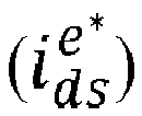
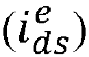
- the comparator (42) compares a flux current command value i d ⁇ s e * inputted from outside with an actually outputted flux current i d ⁇ s e and outputs the comparison.
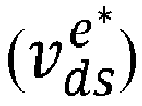
- the current controller (36) generates a torque current and a flux current outputted after being compared by the comparators (35, 42) through a controller as a flux voltage command value v d ⁇ s e * and torque voltage command value v q ⁇ s e * and outputs same.
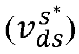
- the voltage coordinate converter (37) converts the flux voltage command value v d ⁇ s e * and the torque voltage command value v q ⁇ s e * outputted from the current controller (6) on the rotation coordinate to the flux voltage command value v d ⁇ s e * and the torque voltage command value v q ⁇ s e * on the stationary coordinate, and outputs same.
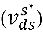
- the 3-phase voltage converter (38) converts the flux voltage command value v d ⁇ s s * and the torque voltage command value v q ⁇ s s * on the stationary coordinate outputted from the voltage coordinate converter (37) to 3-phase voltage ( v as , v bs , v cs ) on the stationary coordinate and outputs same.
- the vector control inverter (39) applies the 3-phase voltages ( v as , v bs , v cs ) of the 3-phase voltage converter (38) to the induction motor (50) and rotates the induction motor.
- the 2-phase current converter (48) receives the 3-phase currents ( i as , i bs , i cs ) detected during rotation of the induction motor (50) and outputs currents i d ⁇ s s , i q ⁇ s s converted to d axis and q axis on the stationary coordinate.
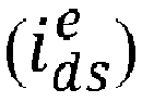
- the current coordinate converter (17) converts the currents i d ⁇ s s , i q ⁇ s s of the stationary coordinate outputted from the 2-phase current converter (48) to actual flux current i d ⁇ s e and torque current i q ⁇ s e of rotation coordinate and outputs the same.
- the slip computing element (44) computes a slip frequency ( ⁇ sl ) using the torque current command value i q ⁇ s e * outputted from the velocity controller (34) and flux current command value i d ⁇ s e * inputted from outside and the induction motor rotor time constant (T r ).
- the computing element (44) computes a slip frequency ( ⁇ sl ) using the torque current command value i q ⁇ s e * outputted from the velocity controller (34), the flux current command value i d ⁇ s e * inputted from outside and the induction motor rotor time constant ( T r ).
- the adder (45) adds the slip frequency ( ⁇ sl ) computed by the slip computing element (44) to the velocity ( ⁇ r ) detected by the velocity detector (49).
- the integrator (46) integrates the value added by the adder (45) to set a position ( ⁇ ) of the rotor flux used by the voltage coordinate converter (37) and the current coordinate converter (47).
- a velocity command is outputted by being multiplied to the command linear velocity applied with the initially-set compensation gain (Comp Gain) value.
- a final command velocity ⁇ r * is outputted by adding the outputted linear velocity to the output of the PID controller (41).
- a command velocity value is changed through the PID controller (41), where, when an output value of the PID controller (41) exceeds a predetermined value (PID output limitation value), the compensation gain computing element (40) automatically adds or deducts the compensation gain (Comp Gain) value to compensate the value through the command linear velocity multiplier (31) to thereby reduce a velocity value changed by the PID controller (41).
- the compensation gain computing element (40) may be defined in detail as illustrated in FIG. 3 .
- the final command velocity computation through the computed compensation gain (Comp Gain) value and the output of the PID controller (11) may be computed based on the following equation 1.
- Command velocity rad / s linear velocity command rad / s * compensation gain CompGain + PID output rad / s
- the comparator (33) receives a rotation velocity ( ⁇ r ) of the velocity detector (49) inputted to an inversion terminal (-) to obtain an error between the two values, and outputs the error to the velocity controller (34).
- An output of the velocity controller (34) is inputted to the non-inversion terminal (+) of the comparator (35).
- the flux current command value i d ⁇ s e * inputted from the outside is inputted to the non-inversion terminal (+) of the comparator (42).
- the 3-phase currents ( i as , i bs , i cs ) detected from the induction motor (50) during rotation of the induction motor (50) are outputted by the 2-phase current converter (48) as stationary coordinate 2-phase currents i d ⁇ s s , i q ⁇ s s .
- the stationary coordinate 2-phase currents i d ⁇ s s , i q ⁇ s s outputted by the 2-phase current converter (48) are inputted to the current coordinate converter (47) to be outputted as actual flux current i d ⁇ s e and torque current i q ⁇ s e of the rotation coordinate, whereby the flux current i d ⁇ s e outputted from the current coordinate converter (47) is outputted to the inversion terminal (-) of the comparator (42).
- the comparator (42) obtains an error between the flux current command value i d ⁇ s e * inputted from the outside and the actual flux current i d ⁇ s e outputted from the current coordinate converter (47) and outputs the error to the current controller (36).
- the comparator (35) receives the torque current command value i q ⁇ s e * outputted from the velocity controller (34) at the non-inversion terminal (+), and receives the actual torque current i q ⁇ s e outputted from the current coordinate converter (47) at the inversion terminal (-) to obtain an error between the two values, and outputs the error thus obtained to the current controller (36).
- the current controller (36) that has received the torque current outputted from the comparator (35) and the flux current outputted from the comparator (42) outputs the flux voltage command value v d ⁇ s e * and the torque voltage command value v q ⁇ s e * to the voltage coordinate converter (47) through the control.
- the voltage coordinate converter (37) receives the flux voltage command value v d ⁇ s s * and the torque voltage command value v q ⁇ s s * and converts the received flux voltage command value v d ⁇ s s * and the torque voltage command value v q ⁇ s s * to 3-phase voltages ( v as , v bs , v cs ) through the 3-phase voltage converter (38) and provides to the vector control inverter (39).
- the vector control inverter (39) applies the 3-phase voltages ( v as , v bs , V cs ) to the induction motor (50), whereby the induction motor (50) is rotated to generate the actual flux current i d ⁇ s e and the torque current i q ⁇ s e converted to d axis and q axis from the actual rotation coordinate through the current coordinate converter (47) and the 2-phase current converter (48), where the flux current i d ⁇ s e among the current thus generated is outputted to the comparator (42), and the torque current i q ⁇ s e is outputted to the comparator (35).
- the slip computing element (44) computes a slip frequency ( ⁇ sl ) using the torque current command value i q ⁇ s e * outputted from the velocity controller (34), the flux current command value i d ⁇ s e * inputted from outside and the induction motor rotor time constant ( T r ), and outputs to a terminal at one side of the adder (45).
- the adder (45) adds the velocity ( ⁇ r ) outputted from the velocity detector (49) to the slip frequency ( ⁇ sl ) outputted from the slip computing element (44) and outputs the addition to the integrator (46), where the integrator (46) outputs a value integrated to the value outputted from the adder (45), i.e., the position ( ⁇ ) of the rotor flux to the voltage coordinate converter (37) and the current coordinate converter (47).
- the voltage coordinate converter (37) and the current coordinate converter (47) controls the coordinate conversion in response to the position ( ⁇ ) of the rotor flux inputted from the integrator (46).
- the first advantageous effect from the vector control apparatus of induction motor according to an exemplary embodiment of the present disclosure is that compensation gain is computed by using an output value of PID controller by the compensation gain computing element.
- the second advantageous effect is to realize a diameter computation-free winder velocity control algorithm for constantly maintaining a tension using no diameter computation by compensating, without diameter computation, a linear velocity for maintaining a tension, aside from a PID controller by applying a computed compensation gain to a command linear velocity.
Landscapes
- Engineering & Computer Science (AREA)
- Power Engineering (AREA)
- Control Of Ac Motors In General (AREA)
Abstract
Description
- The teachings in accordance with the exemplary embodiments of this present disclosure generally relate to a vector control apparatus of induction motor, and more particularly to a vector control apparatus of induction motor configured to be operated by a winder control algorithm free from diameter computation.
- Several motors simultaneously drive rollers on continuous product manufacturing lines such as steel, paper, textile and film manufacturing industries. The purpose of controlling rollers in the continuous processing is to constantly maintain a line speed of line and to simultaneously maintain a tension on materials. When an excessively high tension is generated on rollers due to speed deviation, materials may be ruptured, and when an excessively low tension is generated, meandering may be generated. When a high level controller in the continuous processing system calculates a diameter of material and motor command torque in response to linear velocity command, and instructs an inverter, the inverter drives the motor in response to the command torque. Thus, an accurate control of a motor by an inverter may determine a stable operation of rollers in the continuous product manufacturing lines.
- An exemplary embodiment of the present disclosure is to provide a vector control apparatus of induction motor configured to be operated by a winder control algorithm free from diameter computation, whereby operational reliability can be enhanced.
- In one general aspect of the present disclosure, there is provided a vector control apparatus configured to control tension of a motor free from diameter computation, the vector control apparatus comprising:
- a tension velocity generator configured to generate command velocity information for constantly maintaining a tension of a motor by adding a PID (Proportional Integral Differential) output value to a value computing a compensation gain value substituting a diameter computation value of a motor to be controlled and a command linear velocity provided from outside are computed; and
- a vector controller configured to perform a tension control of the motor by receiving the command velocity information provided the tension velocity generator.
- Preferably, but not necessarily, the tension velocity generator may include a comparator configured to compare a PID command inputted from the outside with a PID feedback value and to output an error of PID value in response to the comparison, a PID controller configured to output a PID output for compensating the error of the PID value outputted from the comparator, a compensation gain computing element configured to compute a compensation gain corresponding to a diameter value of the motor by determining the PID output, a multiplier configured to multiply a command velocity provided from outside for control of the motor by the compensation gain, and an adder configured to add a command velocity outputted from the multiplier and a PID output outputted from the PID controller.
- Preferably, but not necessarily, a final command velocity computation configured to control the motor by the vector control apparatus may be computed based on the a formula of (command velocity [rad/s] = {(linear velocity command [rad/s] * compensation gain(CompGain))+PID output [rad/s]}.
- The vector control apparatus of induction motor according to an exemplary embodiment of the present disclosure has a first advantageous effect in that compensation gain is computed by using an output value of PID controller by the compensation gain computing element.
- The second advantageous effect is to realize a diameter computation-free winder velocity control algorithm for constantly maintaining a tension using no diameter computation by compensating, without diameter computation, a linear velocity for maintaining a tension, aside from a PID controller by applying a computed compensation gain to a command linear velocity.
-
-
FIG. 1 is a block diagram illustrating a diameter computation-free velocity control winder algorithm according to an exemplary embodiment of the present disclosure. -
FIG. 2 is a block diagram illustrating a diameter computation-free velocity control winder algorithm according to another exemplary embodiment of the present disclosure. -
FIG. 3 is a block diagram illustrating a compensation gain computing element ofFIG. 2 . - Hereinafter, features and advantages of the disclosed embodiments will be or will become apparent to one of ordinary skill in the art upon examination of the following figures and detailed description. The vector control apparatus of induction according to exemplary embodiments of the present disclosure will be described in detail with reference to the accompanying drawings.
- The present disclosure relates to a diameter computation-free winder velocity control algorithm capable of performing a tension control with no material rupture and meandering by constantly maintaining a tension of an inverter through computation of command torque of a motor in response to actual diameter change of material using no diameter computation when a linear velocity and a reference tension are instructed to the inverter in a continuous processing line.
- An inverter drives a motor by performing a motor command velocity and tension control in response to a material diameter. In this case, the inverter uses a diameter computation algorithm and controls the motor command velocity and tension control using a diameter obtained therefrom, where a tension PID controller compensates an instantaneous tension.
- In performing a motor command torque and tension control using a PID controller by installing a winder function on a vector inverter, the present disclosure is configured to improve an inverter function by proposing a new diameter computation-free velocity control winder algorithm using no diameter computation of material.
-
FIG. 1 is a block diagram illustrating a vector control apparatus of induction motor according to an exemplary embodiment of the present disclosure. - Referring to
FIG. 1 , the vector control apparatus of induction motor includes a tension velocity generator (100) and a vector controller (200). The tension velocity generator (100) includes a comparator (10), a PID controller (11), a diameter computing element (12), an adder (1) and a command velocity computing element (2). - The comparator (10) compares a command velocity inputted from outside, a PID command inputted from outside and an actual PID feedback value (Fbk), and outputs an error in response to the comparison thereof. The PID controller (11) outputs a PID output for compensating an error of the PID value outputted from the comparator (10). The adder (1) adds a command velocity inputted from outside to a PID output outputted from the PID controller (11). The diameter computing element (12) computes a diameter using a command linear velocity, a maximum velocity (RPMmax) and a minimum diameter (Dmin) of a motor at a command linear velocity and a maximum linear velocity command, and a rotation velocity detected by a velocity detector (19). The command velocity computing element (2) computes a command velocity by applying a diameter value obtained from the diameter computing element (12) to the velocity outputted from the adder (1).
- The vector controller (200) includes a comparator (3), a velocity controller (4), a comparator (5), a current controller (6), a voltage coordinate converter (7), a 3-phase voltage converter (8), a vector control inverter (9), a comparator (13), a slip computing element (14), an adder (15), an integrator (16), a current coordinate converter (17), and a current converter (18).
- The comparator (3) compares a rotation velocity (ωr ) detected by the velocity detector (19) with a command value


- The 3-phase voltage converter (8) converts a flux voltage command value


- A 2-pase current converter (18) receives 3-phase currents (ias, ibs, ics) detected during rotation of the induction motor (20) and outputs currents




- Successively the vector control apparatus illustrated in
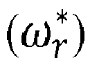
FIG. 1 will be described. When the induction motor (20) is rotated, the velocity detector (19) detects the rotation velocity (ω r ) and outputs the detected velocity. A command velocity inputted from outside, a PID command inputted from outside and an actual PID feedback value (Fbk) are compared, and a velocity is outputted to the adder (1) in which an output of the PID controller (11) is added that outputs a PID output for compensating an output error of the comparator (10) outputting an error in response to the comparison. - When an output of the command velocity computing element (2) computing a final velocity command
- Furthermore, a flux current command value

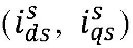


- The voltage coordinate converter (7) receives the flux voltage command value


- Then, the adder (15) adds a velocity (ω r ) outputted from the velocity detector (19) and the slip frequency (ω sl ) outputted from the slip computing element (14) and outputs the addition to the integrator (16), where the integrator (16) outputs a value integrated to a value outputted from the adder (15), i.e., a position (θ) of rotor flux to the voltage coordinate converter (7) and the current coordinate converter (17). Thus, the voltage coordinate converter (7) and the current coordinate converter (17) controls a coordinate conversion in response to the position (θ) of the rotor flux inputted from the integrator (16), and subsequent operation is as mentioned before.
- The vector control apparatus thus described outputs a command velocity by applying basically computed diameter value for obtaining a torque command for maintaining a tension. At this time, in order to compute a diameter, a user must learn an accurate maximum linear velocity, bobbin diameter and gear ratio of winder system. However, there are cases where various diameters of bobbin are actually used and an accurate measurement value for diameter computation cannot be obtained, where, if no computation function is not used, the torque command changed value in response to actual diameter change is compensated only by a PID controller. In this case, a quick control in response to the instantaneous change cannot be performed due to saturation of the PID controller. Thus, a need is proposed to a control technique capable of coping with an actual diameter change without saturation of output value of the PID controller.
- To this end, the vector control apparatus according to the present disclosure is configured such that when an upper level controller instructs a linear velocity and tension to an inverter, a command linear velocity is computed by applying, to the applied linear velocity, a compensation gain (Comp Gain) substitutable of diameter value, and a command velocity is computed for constantly maintaining a tension by adding a computed PID controller output value to the command linear velocity using the tension measurement value obtained through the applied tension command and tension sensor.
- At this time, the PID controller output value is used for compensation gain computation lest saturation be generated. An improvement of an inverter using a vector control method can be expected by realizing a diameter computing element-free, diameter computation-free winder control algorithm on a continuous process lines that drives a motor using a calculated final command velocity.
-
FIG. 2 is a block diagram illustrating a diameter computation-free velocity control winder algorithm according to another exemplary embodiment of the present disclosure, andFIG. 3 is a block diagram illustrating a compensation gain computing element ofFIG. 2 . - Referring to
FIG. 2 , the vector control apparatus configured to realize a diameter computation-free winder control algorithm according to an exemplary embodiment of the present disclosure includes a tension velocity generator (300) and a vector controller (400). - The tension velocity generator (300) includes a multiplier (31), an adder (32), a compensation gain computing element (40), a PID controller (41) and a comparator (43). The multiplier (31) provides a command velocity in which a command velocity provided from outside for motor (50) control is multiplied by a compensation gain outputted from the compensation gain computing element (40). The adder (32) adds the command velocity outputted from the multiplier (31) and the PID output outputted from the PID controller (41). The comparator (43) compares a PID command inputted from outside with a PID feedback value (Fbk), and outputs an error resultant from the comparison. The PID controller (41) outputs a PID output for compensating an error of PID value outputted from the comparator (43). The compensation gain computing element (40) computes a compensation gain corresponding to a diameter value of the motor by determining the PID output of the PID controller (41).
- Furthermore, the velocity detector detects a rotation velocity of the induction motor (50). The vector controller (400) includes a comparator (33), a velocity controller (34), a comparator (35), a current controller (36), a voltage coordinate converter (37), a 3-phase voltage converter (38), a vector control inverter (39), a comparator (42), a slip computing element (44), an adder (45), an integrator (46), a current coordinate converter (47) and a current converter (48).
- The comparator (33) compares a rotation velocity (ω r ) detected by the velocity detector (49) with a command value



- The current controller (36) generates a torque current and a flux current outputted after being compared by the comparators (35, 42) through a controller as a flux voltage command value

- The voltage coordinate converter (37) converts the flux voltage command value


- The 3-phase voltage converter (38) converts the flux voltage command value


- The current coordinate converter (17) converts the currents



- The computing element (44) computes a slip frequency (ω sl ) using the torque current command value


- Now, the vector control apparatus of induction motor thus configured according to an exemplary embodiment of the present disclosure will be described in detail.
- A velocity command is outputted by being multiplied to the command linear velocity applied with the initially-set compensation gain (Comp Gain) value. A final command velocity

FIG. 3 . - The final command velocity computation through the computed compensation gain (Comp Gain) value and the output of the PID controller (11) may be computed based on the
following equation 1.
- When the velocity command value


- Successively, the comparator (42) obtains an error between the flux current command value





- Furthermore, the slip computing element (44) computes a slip frequency (ωsl) using the torque current command value


- The first advantageous effect from the vector control apparatus of induction motor according to an exemplary embodiment of the present disclosure is that compensation gain is computed by using an output value of PID controller by the compensation gain computing element.
- The second advantageous effect is to realize a diameter computation-free winder velocity control algorithm for constantly maintaining a tension using no diameter computation by compensating, without diameter computation, a linear velocity for maintaining a tension, aside from a PID controller by applying a computed compensation gain to a command linear velocity.
- Although the present disclosure has been described in detail with reference to the foregoing embodiments and advantages, many alternatives, modifications, and variations will be apparent to those skilled in the art within the metes and bounds of the claims. Therefore, it should be understood that the above-described embodiments are not limited by any of the details of the foregoing description, unless otherwise specified, but rather should be construed broadly within the scope as defined in the appended claims.
Claims (3)
- A vector control apparatus configured to control tension of a motor (50) free from diameter computation, the vector control apparatus characterized by:a tension velocity generator (300) configured to generate command velocity information for constantly maintaining a tension of the motor (50) by adding a PID (Proportional Integral Differential) output value to a value computing a compensation gain value substituting a diameter computation value of a motor to be controlled and a command linear velocity provided from outside; anda vector controller (400) configured to perform a tension control of the motor (50) by receiving the command velocity information provided the tension velocity generator (300).
- The vector control apparatus of claim 1, characterized in that the tension velocity generator (300) includes a comparator (43) configured to compare a PID command inputted from the outside with a PID feedback value and to output an error of PID value in response to the comparison, a PID controller (41) configured to output a PID output for compensating the error of the PID value outputted from the comparator, a compensation gain computing element (40) configured to compute a compensation gain corresponding to a diameter value of the motor (50) by determining the PID output, a multiplier (31) configured to multiply a command velocity provided from the outside for control of the motor by the compensation gain, and an adder (32) configured to add a command velocity outputted from the multiplier (31) and a PID output outputted from the PID controller (41).
- The vector control apparatus of claim 1, characterized in that a final command velocity computation configured to control the motor (50) by the vector control apparatus is computed based on the a formula of (command velocity [rad/s] = {(linear velocity command [rad/s] * compensation gain(CompGain))+PID output [rad/s]}.
Applications Claiming Priority (1)
| Application Number | Priority Date | Filing Date | Title |
|---|---|---|---|
| KR1020130077695A KR101460444B1 (en) | 2013-07-03 | 2013-07-03 | Vector controller of induction motor |
Publications (3)
| Publication Number | Publication Date |
|---|---|
| EP2822176A2 true EP2822176A2 (en) | 2015-01-07 |
| EP2822176A3 EP2822176A3 (en) | 2015-12-23 |
| EP2822176B1 EP2822176B1 (en) | 2019-03-20 |
Family
ID=50981014
Family Applications (1)
| Application Number | Title | Priority Date | Filing Date |
|---|---|---|---|
| EP14174090.2A Active EP2822176B1 (en) | 2013-07-03 | 2014-06-26 | Vector control apparatus of induction motor |
Country Status (6)
| Country | Link |
|---|---|
| US (1) | US9178459B2 (en) |
| EP (1) | EP2822176B1 (en) |
| JP (1) | JP5941103B2 (en) |
| KR (1) | KR101460444B1 (en) |
| CN (1) | CN104283476B (en) |
| ES (1) | ES2728756T3 (en) |
Families Citing this family (2)
| Publication number | Priority date | Publication date | Assignee | Title |
|---|---|---|---|---|
| JP2016046859A (en) * | 2014-08-20 | 2016-04-04 | 株式会社リコー | Motor drive control device and motor drive control method |
| CN110413014B (en) * | 2019-08-29 | 2022-01-28 | 河南东旺熙朝实业有限公司 | Speed control circuit of aluminum extruder |
Family Cites Families (16)
| Publication number | Priority date | Publication date | Assignee | Title |
|---|---|---|---|---|
| JPS5851770B2 (en) * | 1979-07-06 | 1983-11-18 | 川崎製鉄株式会社 | Tension control method and device |
| JPH0694614B2 (en) * | 1983-02-25 | 1994-11-24 | 津田駒工業株式会社 | Electric loom feeding method and device |
| JPH0811245B2 (en) * | 1987-03-13 | 1996-02-07 | 株式会社東芝 | Looper control device for continuous rolling mill |
| JPS63251804A (en) | 1987-04-08 | 1988-10-19 | Fuji Electric Co Ltd | Setting method for feedback gain of tension controller |
| JPH01259778A (en) | 1988-04-06 | 1989-10-17 | Fuji Electric Co Ltd | Tension controller |
| JPH0218263A (en) | 1988-07-05 | 1990-01-22 | Toray Eng Co Ltd | Inverter |
| JP2550801B2 (en) | 1991-06-25 | 1996-11-06 | 株式会社ニレコ | Tension control device |
| EP0745890A1 (en) * | 1995-05-30 | 1996-12-04 | Eastman Kodak Company | Film web motion control system |
| JPH0930700A (en) * | 1995-07-19 | 1997-02-04 | Toshiba Corp | Motor drive |
| JP2002154748A (en) | 2000-11-20 | 2002-05-28 | Mitsubishi Electric Corp | Variable speed device for winding machine |
| JP4168076B2 (en) * | 2007-03-08 | 2008-10-22 | ファナック株式会社 | Wire cut electric discharge machine with wire electrode tension control function |
| JP5125370B2 (en) * | 2007-10-01 | 2013-01-23 | ブラザー工業株式会社 | Drive control device and drive control method |
| KR20090096829A (en) * | 2008-03-10 | 2009-09-15 | 엘에스산전 주식회사 | Vector inverter device of electric motor for winder |
| JP4867978B2 (en) * | 2008-11-14 | 2012-02-01 | 株式会社デンソー | Motor and control device thereof |
| DE112011100347B4 (en) * | 2010-01-27 | 2020-07-23 | Mitsubishi Electric Corporation | Engine control device |
| KR101202884B1 (en) * | 2011-07-05 | 2012-11-19 | 엘에스산전 주식회사 | Apparatus for controlling speed in induction motor |
-
2013
- 2013-07-03 KR KR1020130077695A patent/KR101460444B1/en active Active
-
2014
- 2014-06-25 US US14/314,929 patent/US9178459B2/en active Active
- 2014-06-26 EP EP14174090.2A patent/EP2822176B1/en active Active
- 2014-06-26 ES ES14174090T patent/ES2728756T3/en active Active
- 2014-07-02 CN CN201410382156.0A patent/CN104283476B/en active Active
- 2014-07-03 JP JP2014137862A patent/JP5941103B2/en not_active Expired - Fee Related
Non-Patent Citations (1)
| Title |
|---|
| None |
Also Published As
| Publication number | Publication date |
|---|---|
| US9178459B2 (en) | 2015-11-03 |
| CN104283476A (en) | 2015-01-14 |
| JP5941103B2 (en) | 2016-06-29 |
| US20150008863A1 (en) | 2015-01-08 |
| KR101460444B1 (en) | 2014-11-10 |
| CN104283476B (en) | 2018-04-03 |
| JP2015015890A (en) | 2015-01-22 |
| ES2728756T3 (en) | 2019-10-28 |
| EP2822176B1 (en) | 2019-03-20 |
| EP2822176A3 (en) | 2015-12-23 |
Similar Documents
| Publication | Publication Date | Title |
|---|---|---|
| JP4411796B2 (en) | Control system, observer and control method for induction motor drive without speed sensor | |
| EP1944862B1 (en) | Induction motor controller | |
| EP2544363B1 (en) | Apparatus for controlling speed in induction motor | |
| JP5327700B2 (en) | Induction motor control device and control method thereof | |
| EP3157162A1 (en) | Motor control device, and method for correcting torque constant in such motor control device | |
| US8183816B2 (en) | Method for field-oriented operation to zero speed of an encoder-less asynchronous machine | |
| US7385371B2 (en) | Vector controller for induction motor | |
| WO2018011863A1 (en) | Inverter device | |
| US10116250B2 (en) | AC-rotary-machine control device and electric power-steering system provided with AC-rotary-machine control device | |
| EP2822176B1 (en) | Vector control apparatus of induction motor | |
| CN117792178A (en) | Motor control method, device and computer-readable storage medium | |
| CN102983805A (en) | Control device of AC motor | |
| KR20090096829A (en) | Vector inverter device of electric motor for winder | |
| EP4462671A1 (en) | Drive device for induction motor | |
| KR0129561B1 (en) | Vector control unit for induction motor | |
| KR101202927B1 (en) | Apparatus for controlling speed in induction motor | |
| CN106877770B (en) | Torque control device and torque control system for electric motor | |
| KR100771914B1 (en) | Vector inverter control unit for winder | |
| JP5228436B2 (en) | Motor control device and control method thereof | |
| JP4839552B2 (en) | Induction motor control method | |
| KR101406537B1 (en) | Torque control winder using vector inverter | |
| JPH11136999A (en) | Variable speed driver for induction machine | |
| JP2018107976A (en) | Variable speed gear during dc braking of induction machine, and control method therefor | |
| KR101736006B1 (en) | Apparatus for correcting of current compensator | |
| JPH06209590A (en) | Vector controller for induction motor |
Legal Events
| Date | Code | Title | Description |
|---|---|---|---|
| PUAI | Public reference made under article 153(3) epc to a published international application that has entered the european phase |
Free format text: ORIGINAL CODE: 0009012 |
|
| 17P | Request for examination filed |
Effective date: 20140626 |
|
| AK | Designated contracting states |
Kind code of ref document: A2 Designated state(s): AL AT BE BG CH CY CZ DE DK EE ES FI FR GB GR HR HU IE IS IT LI LT LU LV MC MK MT NL NO PL PT RO RS SE SI SK SM TR |
|
| AX | Request for extension of the european patent |
Extension state: BA ME |
|
| PUAL | Search report despatched |
Free format text: ORIGINAL CODE: 0009013 |
|
| AK | Designated contracting states |
Kind code of ref document: A3 Designated state(s): AL AT BE BG CH CY CZ DE DK EE ES FI FR GB GR HR HU IE IS IT LI LT LU LV MC MK MT NL NO PL PT RO RS SE SI SK SM TR |
|
| AX | Request for extension of the european patent |
Extension state: BA ME |
|
| RIC1 | Information provided on ipc code assigned before grant |
Ipc: H02P 21/00 20060101AFI20151116BHEP |
|
| R17P | Request for examination filed (corrected) |
Effective date: 20160622 |
|
| RBV | Designated contracting states (corrected) |
Designated state(s): AL AT BE BG CH CY CZ DE DK EE ES FI FR GB GR HR HU IE IS IT LI LT LU LV MC MK MT NL NO PL PT RO RS SE SI SK SM TR |
|
| STAA | Information on the status of an ep patent application or granted ep patent |
Free format text: STATUS: EXAMINATION IS IN PROGRESS |
|
| 17Q | First examination report despatched |
Effective date: 20171214 |
|
| GRAP | Despatch of communication of intention to grant a patent |
Free format text: ORIGINAL CODE: EPIDOSNIGR1 |
|
| STAA | Information on the status of an ep patent application or granted ep patent |
Free format text: STATUS: GRANT OF PATENT IS INTENDED |
|
| INTG | Intention to grant announced |
Effective date: 20181115 |
|
| RAP1 | Party data changed (applicant data changed or rights of an application transferred) |
Owner name: LSIS CO., LTD. |
|
| GRAS | Grant fee paid |
Free format text: ORIGINAL CODE: EPIDOSNIGR3 |
|
| GRAA | (expected) grant |
Free format text: ORIGINAL CODE: 0009210 |
|
| STAA | Information on the status of an ep patent application or granted ep patent |
Free format text: STATUS: THE PATENT HAS BEEN GRANTED |
|
| AK | Designated contracting states |
Kind code of ref document: B1 Designated state(s): AL AT BE BG CH CY CZ DE DK EE ES FI FR GB GR HR HU IE IS IT LI LT LU LV MC MK MT NL NO PL PT RO RS SE SI SK SM TR |
|
| REG | Reference to a national code |
Ref country code: GB Ref legal event code: FG4D |
|
| REG | Reference to a national code |
Ref country code: CH Ref legal event code: EP |
|
| REG | Reference to a national code |
Ref country code: DE Ref legal event code: R096 Ref document number: 602014043156 Country of ref document: DE |
|
| REG | Reference to a national code |
Ref country code: AT Ref legal event code: REF Ref document number: 1111540 Country of ref document: AT Kind code of ref document: T Effective date: 20190415 |
|
| REG | Reference to a national code |
Ref country code: IE Ref legal event code: FG4D |
|
| REG | Reference to a national code |
Ref country code: NL Ref legal event code: MP Effective date: 20190320 |
|
| PG25 | Lapsed in a contracting state [announced via postgrant information from national office to epo] |
Ref country code: SE Free format text: LAPSE BECAUSE OF FAILURE TO SUBMIT A TRANSLATION OF THE DESCRIPTION OR TO PAY THE FEE WITHIN THE PRESCRIBED TIME-LIMIT Effective date: 20190320 Ref country code: LT Free format text: LAPSE BECAUSE OF FAILURE TO SUBMIT A TRANSLATION OF THE DESCRIPTION OR TO PAY THE FEE WITHIN THE PRESCRIBED TIME-LIMIT Effective date: 20190320 Ref country code: NO Free format text: LAPSE BECAUSE OF FAILURE TO SUBMIT A TRANSLATION OF THE DESCRIPTION OR TO PAY THE FEE WITHIN THE PRESCRIBED TIME-LIMIT Effective date: 20190620 Ref country code: FI Free format text: LAPSE BECAUSE OF FAILURE TO SUBMIT A TRANSLATION OF THE DESCRIPTION OR TO PAY THE FEE WITHIN THE PRESCRIBED TIME-LIMIT Effective date: 20190320 |
|
| REG | Reference to a national code |
Ref country code: LT Ref legal event code: MG4D |
|
| PG25 | Lapsed in a contracting state [announced via postgrant information from national office to epo] |
Ref country code: BG Free format text: LAPSE BECAUSE OF FAILURE TO SUBMIT A TRANSLATION OF THE DESCRIPTION OR TO PAY THE FEE WITHIN THE PRESCRIBED TIME-LIMIT Effective date: 20190620 Ref country code: RS Free format text: LAPSE BECAUSE OF FAILURE TO SUBMIT A TRANSLATION OF THE DESCRIPTION OR TO PAY THE FEE WITHIN THE PRESCRIBED TIME-LIMIT Effective date: 20190320 Ref country code: NL Free format text: LAPSE BECAUSE OF FAILURE TO SUBMIT A TRANSLATION OF THE DESCRIPTION OR TO PAY THE FEE WITHIN THE PRESCRIBED TIME-LIMIT Effective date: 20190320 Ref country code: LV Free format text: LAPSE BECAUSE OF FAILURE TO SUBMIT A TRANSLATION OF THE DESCRIPTION OR TO PAY THE FEE WITHIN THE PRESCRIBED TIME-LIMIT Effective date: 20190320 Ref country code: GR Free format text: LAPSE BECAUSE OF FAILURE TO SUBMIT A TRANSLATION OF THE DESCRIPTION OR TO PAY THE FEE WITHIN THE PRESCRIBED TIME-LIMIT Effective date: 20190621 Ref country code: HR Free format text: LAPSE BECAUSE OF FAILURE TO SUBMIT A TRANSLATION OF THE DESCRIPTION OR TO PAY THE FEE WITHIN THE PRESCRIBED TIME-LIMIT Effective date: 20190320 |
|
| REG | Reference to a national code |
Ref country code: AT Ref legal event code: MK05 Ref document number: 1111540 Country of ref document: AT Kind code of ref document: T Effective date: 20190320 |
|
| REG | Reference to a national code |
Ref country code: ES Ref legal event code: FG2A Ref document number: 2728756 Country of ref document: ES Kind code of ref document: T3 Effective date: 20191028 |
|
| PG25 | Lapsed in a contracting state [announced via postgrant information from national office to epo] |
Ref country code: SK Free format text: LAPSE BECAUSE OF FAILURE TO SUBMIT A TRANSLATION OF THE DESCRIPTION OR TO PAY THE FEE WITHIN THE PRESCRIBED TIME-LIMIT Effective date: 20190320 Ref country code: PT Free format text: LAPSE BECAUSE OF FAILURE TO SUBMIT A TRANSLATION OF THE DESCRIPTION OR TO PAY THE FEE WITHIN THE PRESCRIBED TIME-LIMIT Effective date: 20190720 Ref country code: AL Free format text: LAPSE BECAUSE OF FAILURE TO SUBMIT A TRANSLATION OF THE DESCRIPTION OR TO PAY THE FEE WITHIN THE PRESCRIBED TIME-LIMIT Effective date: 20190320 Ref country code: EE Free format text: LAPSE BECAUSE OF FAILURE TO SUBMIT A TRANSLATION OF THE DESCRIPTION OR TO PAY THE FEE WITHIN THE PRESCRIBED TIME-LIMIT Effective date: 20190320 Ref country code: RO Free format text: LAPSE BECAUSE OF FAILURE TO SUBMIT A TRANSLATION OF THE DESCRIPTION OR TO PAY THE FEE WITHIN THE PRESCRIBED TIME-LIMIT Effective date: 20190320 Ref country code: CZ Free format text: LAPSE BECAUSE OF FAILURE TO SUBMIT A TRANSLATION OF THE DESCRIPTION OR TO PAY THE FEE WITHIN THE PRESCRIBED TIME-LIMIT Effective date: 20190320 |
|
| PG25 | Lapsed in a contracting state [announced via postgrant information from national office to epo] |
Ref country code: SM Free format text: LAPSE BECAUSE OF FAILURE TO SUBMIT A TRANSLATION OF THE DESCRIPTION OR TO PAY THE FEE WITHIN THE PRESCRIBED TIME-LIMIT Effective date: 20190320 Ref country code: PL Free format text: LAPSE BECAUSE OF FAILURE TO SUBMIT A TRANSLATION OF THE DESCRIPTION OR TO PAY THE FEE WITHIN THE PRESCRIBED TIME-LIMIT Effective date: 20190320 |
|
| PG25 | Lapsed in a contracting state [announced via postgrant information from national office to epo] |
Ref country code: IS Free format text: LAPSE BECAUSE OF FAILURE TO SUBMIT A TRANSLATION OF THE DESCRIPTION OR TO PAY THE FEE WITHIN THE PRESCRIBED TIME-LIMIT Effective date: 20190720 Ref country code: AT Free format text: LAPSE BECAUSE OF FAILURE TO SUBMIT A TRANSLATION OF THE DESCRIPTION OR TO PAY THE FEE WITHIN THE PRESCRIBED TIME-LIMIT Effective date: 20190320 |
|
| REG | Reference to a national code |
Ref country code: DE Ref legal event code: R097 Ref document number: 602014043156 Country of ref document: DE |
|
| PLBE | No opposition filed within time limit |
Free format text: ORIGINAL CODE: 0009261 |
|
| STAA | Information on the status of an ep patent application or granted ep patent |
Free format text: STATUS: NO OPPOSITION FILED WITHIN TIME LIMIT |
|
| PG25 | Lapsed in a contracting state [announced via postgrant information from national office to epo] |
Ref country code: MC Free format text: LAPSE BECAUSE OF FAILURE TO SUBMIT A TRANSLATION OF THE DESCRIPTION OR TO PAY THE FEE WITHIN THE PRESCRIBED TIME-LIMIT Effective date: 20190320 Ref country code: DK Free format text: LAPSE BECAUSE OF FAILURE TO SUBMIT A TRANSLATION OF THE DESCRIPTION OR TO PAY THE FEE WITHIN THE PRESCRIBED TIME-LIMIT Effective date: 20190320 |
|
| REG | Reference to a national code |
Ref country code: CH Ref legal event code: PL |
|
| 26N | No opposition filed |
Effective date: 20200102 |
|
| PG25 | Lapsed in a contracting state [announced via postgrant information from national office to epo] |
Ref country code: SI Free format text: LAPSE BECAUSE OF FAILURE TO SUBMIT A TRANSLATION OF THE DESCRIPTION OR TO PAY THE FEE WITHIN THE PRESCRIBED TIME-LIMIT Effective date: 20190320 |
|
| REG | Reference to a national code |
Ref country code: BE Ref legal event code: MM Effective date: 20190630 |
|
| PG25 | Lapsed in a contracting state [announced via postgrant information from national office to epo] |
Ref country code: TR Free format text: LAPSE BECAUSE OF FAILURE TO SUBMIT A TRANSLATION OF THE DESCRIPTION OR TO PAY THE FEE WITHIN THE PRESCRIBED TIME-LIMIT Effective date: 20190320 |
|
| PG25 | Lapsed in a contracting state [announced via postgrant information from national office to epo] |
Ref country code: IE Free format text: LAPSE BECAUSE OF NON-PAYMENT OF DUE FEES Effective date: 20190626 |
|
| PG25 | Lapsed in a contracting state [announced via postgrant information from national office to epo] |
Ref country code: BE Free format text: LAPSE BECAUSE OF NON-PAYMENT OF DUE FEES Effective date: 20190630 Ref country code: CH Free format text: LAPSE BECAUSE OF NON-PAYMENT OF DUE FEES Effective date: 20190630 Ref country code: LU Free format text: LAPSE BECAUSE OF NON-PAYMENT OF DUE FEES Effective date: 20190626 Ref country code: LI Free format text: LAPSE BECAUSE OF NON-PAYMENT OF DUE FEES Effective date: 20190630 |
|
| PGFP | Annual fee paid to national office [announced via postgrant information from national office to epo] |
Ref country code: FR Payment date: 20200306 Year of fee payment: 7 |
|
| PG25 | Lapsed in a contracting state [announced via postgrant information from national office to epo] |
Ref country code: CY Free format text: LAPSE BECAUSE OF FAILURE TO SUBMIT A TRANSLATION OF THE DESCRIPTION OR TO PAY THE FEE WITHIN THE PRESCRIBED TIME-LIMIT Effective date: 20190320 |
|
| PG25 | Lapsed in a contracting state [announced via postgrant information from national office to epo] |
Ref country code: MT Free format text: LAPSE BECAUSE OF FAILURE TO SUBMIT A TRANSLATION OF THE DESCRIPTION OR TO PAY THE FEE WITHIN THE PRESCRIBED TIME-LIMIT Effective date: 20190320 Ref country code: HU Free format text: LAPSE BECAUSE OF FAILURE TO SUBMIT A TRANSLATION OF THE DESCRIPTION OR TO PAY THE FEE WITHIN THE PRESCRIBED TIME-LIMIT; INVALID AB INITIO Effective date: 20140626 |
|
| PG25 | Lapsed in a contracting state [announced via postgrant information from national office to epo] |
Ref country code: FR Free format text: LAPSE BECAUSE OF NON-PAYMENT OF DUE FEES Effective date: 20210630 |
|
| PG25 | Lapsed in a contracting state [announced via postgrant information from national office to epo] |
Ref country code: MK Free format text: LAPSE BECAUSE OF FAILURE TO SUBMIT A TRANSLATION OF THE DESCRIPTION OR TO PAY THE FEE WITHIN THE PRESCRIBED TIME-LIMIT Effective date: 20190320 |
|
| P01 | Opt-out of the competence of the unified patent court (upc) registered |
Effective date: 20230625 |
|
| PGFP | Annual fee paid to national office [announced via postgrant information from national office to epo] |
Ref country code: DE Payment date: 20250305 Year of fee payment: 12 |
|
| PGFP | Annual fee paid to national office [announced via postgrant information from national office to epo] |
Ref country code: GB Payment date: 20250407 Year of fee payment: 12 |
|
| PGFP | Annual fee paid to national office [announced via postgrant information from national office to epo] |
Ref country code: ES Payment date: 20250714 Year of fee payment: 12 |
|
| PGFP | Annual fee paid to national office [announced via postgrant information from national office to epo] |
Ref country code: IT Payment date: 20260306 Year of fee payment: 13 |