EP2822100A2 - Module émetteur-récepteur, antenne, station de base et procédé de réception de signal - Google Patents
Module émetteur-récepteur, antenne, station de base et procédé de réception de signal Download PDFInfo
- Publication number
- EP2822100A2 EP2822100A2 EP12741752.5A EP12741752A EP2822100A2 EP 2822100 A2 EP2822100 A2 EP 2822100A2 EP 12741752 A EP12741752 A EP 12741752A EP 2822100 A2 EP2822100 A2 EP 2822100A2
- Authority
- EP
- European Patent Office
- Prior art keywords
- transceiving module
- frequency signals
- band radio
- transceiving
- antenna
- Prior art date
- Legal status (The legal status is an assumption and is not a legal conclusion. Google has not performed a legal analysis and makes no representation as to the accuracy of the status listed.)
- Granted
Links
- 238000000034 method Methods 0.000 title claims abstract description 45
- 238000012545 processing Methods 0.000 claims abstract description 80
- 238000003491 array Methods 0.000 claims abstract description 51
- 230000010287 polarization Effects 0.000 claims description 59
- 238000004891 communication Methods 0.000 abstract description 6
- 238000005516 engineering process Methods 0.000 abstract description 2
- 230000006870 function Effects 0.000 description 8
- 230000005540 biological transmission Effects 0.000 description 7
- 238000006243 chemical reaction Methods 0.000 description 6
- 238000010586 diagram Methods 0.000 description 6
- 238000013461 design Methods 0.000 description 4
- 230000009977 dual effect Effects 0.000 description 3
- 238000001914 filtration Methods 0.000 description 3
- 238000004148 unit process Methods 0.000 description 3
- 230000007774 longterm Effects 0.000 description 2
- 238000010295 mobile communication Methods 0.000 description 2
- 238000012986 modification Methods 0.000 description 2
- 230000004048 modification Effects 0.000 description 2
- 238000000605 extraction Methods 0.000 description 1
- 230000003287 optical effect Effects 0.000 description 1
- 230000004044 response Effects 0.000 description 1
Images


Classifications
-
- H—ELECTRICITY
- H01—ELECTRIC ELEMENTS
- H01Q—ANTENNAS, i.e. RADIO AERIALS
- H01Q23/00—Antennas with active circuits or circuit elements integrated within them or attached to them
-
- H—ELECTRICITY
- H04—ELECTRIC COMMUNICATION TECHNIQUE
- H04B—TRANSMISSION
- H04B7/00—Radio transmission systems, i.e. using radiation field
- H04B7/02—Diversity systems; Multi-antenna system, i.e. transmission or reception using multiple antennas
- H04B7/04—Diversity systems; Multi-antenna system, i.e. transmission or reception using multiple antennas using two or more spaced independent antennas
- H04B7/08—Diversity systems; Multi-antenna system, i.e. transmission or reception using multiple antennas using two or more spaced independent antennas at the receiving station
- H04B7/0882—Diversity systems; Multi-antenna system, i.e. transmission or reception using multiple antennas using two or more spaced independent antennas at the receiving station using post-detection diversity
- H04B7/0885—Diversity systems; Multi-antenna system, i.e. transmission or reception using multiple antennas using two or more spaced independent antennas at the receiving station using post-detection diversity with combination
-
- H—ELECTRICITY
- H01—ELECTRIC ELEMENTS
- H01Q—ANTENNAS, i.e. RADIO AERIALS
- H01Q1/00—Details of, or arrangements associated with, antennas
- H01Q1/12—Supports; Mounting means
- H01Q1/22—Supports; Mounting means by structural association with other equipment or articles
- H01Q1/24—Supports; Mounting means by structural association with other equipment or articles with receiving set
- H01Q1/241—Supports; Mounting means by structural association with other equipment or articles with receiving set used in mobile communications, e.g. GSM
- H01Q1/246—Supports; Mounting means by structural association with other equipment or articles with receiving set used in mobile communications, e.g. GSM specially adapted for base stations
-
- H—ELECTRICITY
- H01—ELECTRIC ELEMENTS
- H01Q—ANTENNAS, i.e. RADIO AERIALS
- H01Q25/00—Antennas or antenna systems providing at least two radiating patterns
- H01Q25/001—Crossed polarisation dual antennas
-
- H—ELECTRICITY
- H01—ELECTRIC ELEMENTS
- H01Q—ANTENNAS, i.e. RADIO AERIALS
- H01Q3/00—Arrangements for changing or varying the orientation or the shape of the directional pattern of the waves radiated from an antenna or antenna system
- H01Q3/26—Arrangements for changing or varying the orientation or the shape of the directional pattern of the waves radiated from an antenna or antenna system varying the relative phase or relative amplitude of energisation between two or more active radiating elements; varying the distribution of energy across a radiating aperture
- H01Q3/30—Arrangements for changing or varying the orientation or the shape of the directional pattern of the waves radiated from an antenna or antenna system varying the relative phase or relative amplitude of energisation between two or more active radiating elements; varying the distribution of energy across a radiating aperture varying the relative phase between the radiating elements of an array
- H01Q3/34—Arrangements for changing or varying the orientation or the shape of the directional pattern of the waves radiated from an antenna or antenna system varying the relative phase or relative amplitude of energisation between two or more active radiating elements; varying the distribution of energy across a radiating aperture varying the relative phase between the radiating elements of an array by electrical means
- H01Q3/40—Arrangements for changing or varying the orientation or the shape of the directional pattern of the waves radiated from an antenna or antenna system varying the relative phase or relative amplitude of energisation between two or more active radiating elements; varying the distribution of energy across a radiating aperture varying the relative phase between the radiating elements of an array by electrical means with phasing matrix
-
- H—ELECTRICITY
- H04—ELECTRIC COMMUNICATION TECHNIQUE
- H04B—TRANSMISSION
- H04B1/00—Details of transmission systems, not covered by a single one of groups H04B3/00 - H04B13/00; Details of transmission systems not characterised by the medium used for transmission
- H04B1/38—Transceivers, i.e. devices in which transmitter and receiver form a structural unit and in which at least one part is used for functions of transmitting and receiving
- H04B1/3805—Transceivers, i.e. devices in which transmitter and receiver form a structural unit and in which at least one part is used for functions of transmitting and receiving with built-in auxiliary receivers
-
- H—ELECTRICITY
- H04—ELECTRIC COMMUNICATION TECHNIQUE
- H04B—TRANSMISSION
- H04B7/00—Radio transmission systems, i.e. using radiation field
- H04B7/02—Diversity systems; Multi-antenna system, i.e. transmission or reception using multiple antennas
- H04B7/12—Frequency diversity
Definitions
- the present invention relates to the field of wireless communication technologies, and in particular, to a transceiving module, an antenna, a base station and a signal receiving method.
- a wireless distributed base station system adopts split-structured design of a radio remote unit (Radio Remote Unit, RRU) and a baseband processing unit (Building Base band Unit, BBU).
- RRU Radio Remote Unit
- BBU Building Base band Unit
- a base station antenna system may adopt design of an RRU integrated with an antenna.
- Antenna systems that meet this design requirement include an integrated antenna system and an active antenna system (Active Antenna System, AAS).
- the active antenna system (Active Antenna System, AAS) is widely applied in wireless distributed base stations because the active antenna system has a higher network performance gain than a passive antenna.
- An existing AAS is capable of implementing a performance gain of receiving two dual-band signals.
- the existing AAS adopts two arrays of antennas, where each array of antenna and a set of transceiving unit (Transceiving Unit, referred to as TRX) arrays form a single-band active antenna.
- Each array of antenna includes n antenna elements that have two polarization directions, each set of transceiving unit TRX arrays include 2m TRX transceiving units, and every m TRX transceiving units correspond to a polarization direction.
- Radio-frequency signals received by the n antenna elements in a same polarization direction are sent to m TRX transceiving units via a combining-splitting network, and the m TRX transceiving units send the received radio-frequency signals to a signal processing unit for processing, to implement receiving of one single-band signal.
- Each antenna element of each array of antenna has two polarization directions, so that receiving of two single-band signals can be implemented.
- the two arrays of antennas are capable of implementing receiving of two dual-band signals.
- implementation of receiving only two signals cannot meet a requirement of the uplink network performance of the base station.
- the present invention provides a transceiving module, an antenna, a base station and a signal receiving method, so as to implement receiving of at least four signals with more than one band, thereby improving uplink network performance of a base station.
- One aspect of the present invention provides a transceiving module, including a combining-splitting network, a set of transceiving unit arrays and a signal processing unit that are connected to each other in sequence, and further including a combining network disposed with a connection point connected to another transceiving module, a co-element filter unit separately connected to the combining-splitting network and the combining network, and a pair of receiving units connected to the signal processing unit, where the pair of receiving units in the transceiving module is disposed with a connection point connected to the another transceiving module; where the co-element filter unit includes at least one co-element filter, and is configured to divide two radio-frequency signals received from two polarization directions of antenna elements into two first band radio-frequency signals and two second band radio-frequency signals, where each signal corresponds to a polarization direction, send the two first band radio-frequency signals to the combining-splitting network, and send the two second band radio-frequency signals to the combining network, so that the two first
- Another aspect of the present invention provides an antenna, including a first transceiving module, and at least one antenna element array connected to the first transceiving module, where the first transceiving module is a transceiving module as described above.
- Another aspect of the present invention provides a base station, including the foregoing antenna.
- Another aspect of the present invention provides a signal receiving method, including:
- radio-frequency signals are divided into first band radio-frequency signals and second band radio-frequency signals through multiple co-element filter units, and the first band radio-frequency signals are sent to a set of transceiving unit arrays to implement receiving of two first band radio-frequency signals; first band radio-frequency signals sent by another transceiving module are received through a pair of receiving units, to implement receiving of another two first band radio-frequency signals, thereby implementing receiving of four first band radio-frequency signals; meanwhile, a combining network in the transceiving module sends the second band radio-frequency signals to a pair of receiving units in the another transceiving module, for the pair of receiving units and a signal processing unit that are in the another transceiving module to implement receiving of another two second band radio-frequency signals.
- GSM Global System of Mobile communication
- CDMA Code Division Multiple Access
- WCDMA Wideband Code Division Multiple Access
- GPRS General Packet Radio Service
- LTE Long Term Evolution
- a base station may be a base transceiver station (BTS, Base Transceiver Station) in the GSM or the CDMA, may also be a NodeB (NodeB) in the WCDMA, and may also be an evolved Node B (eNB or e-NodeB, evolved Node B) in the LTE, which is not limited here in the present invention.
- BTS Base Transceiver Station
- NodeB NodeB
- eNB or e-NodeB, evolved Node B evolved Node B
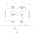
- a transceiving module 1 provided by an embodiment of the present invention includes a co-element filter unit 11, a combining-splitting network 12 and a combining network 13 connected to an output port of first band radio-frequency signals and an output port of second band radio-frequency signals of the co-element filter unit 11 respectively, a set of transceiving unit arrays 14 and a signal processing unit 15 that are connected to the combining-splitting network 12 in sequence, and a pair of receiving units 16 connected to the signal processing unit 15.
- the combining network 13 and the pair of receiving units 16 are separately disposed with a connection point connected to another transceiving module.
- the co-element filter unit 11 includes at least one co-element filter, and is configured to divide two radio-frequency signals received from two polarization directions of antenna elements into two first band radio-frequency signals and two second band radio-frequency signals, send the two first band radio-frequency signals to the combining-splitting network 12, and send the two second band radio-frequency signals to the combining network 13, so that the two first band radio-frequency signals are input to the signal processing unit after being processed by the combining-splitting network and the transceiving unit arrays, where processing of the combining-splitting network may include combining processing such as combining two signals to form one signal or combining three signals to form one signal, and input and output ports of the combining processing are not limited here; processing of the transceiving unit arrays may include processing of converting radio-frequency signals into intermediate-frequency signals, where the intermediate-frequency signals may be analog intermediate-frequency signals or digital intermediate-frequency signals, and may also be other processing, which is not limited here.
- the co-element filter unit may include one co-element filter or multiple co-element filters, where each co-element filter is connected to a same polarization direction of one or multiple antenna elements, and the multiple antenna elements connected to each co-element filter may be adjacent antenna elements.
- the number of co-element filters may be the same as the number of antenna elements; each co-element filter may be disposed with two input ports and four output ports, and is configured to receive two radio-frequency signals received from an antenna element in two polarization directions, and divide the received two radio-frequency signals into two first band radio-frequency signals and two second band radio-frequency signals.
- the number of co-element filters may also be set to twice the number of antenna elements; each co-element filter is disposed with one input port and two output ports, and is configured to receive one radio-frequency signal received from an antenna element in one polarization direction, and divide the received one radio-frequency signal into one first band radio-frequency signal and one second band radio-frequency signal.
- the foregoing merely provides several optional setting manners of the co-element filter unit. It may be understood that, there are multiple manners for setting the number and the ports of co-element filters included in the co-element filter unit, and the present invention is not limited to the foregoing several manners.
- the pair of receiving units 16 is separately configured to receive two first band radio-frequency signals in different polarization directions which are sent by a combining network in the another transceiving module, process the first band radio-frequency signals and send the processed first band radio-frequency signals to the signal processing unit 15, where the processing may include converting the first band radio-frequency signals into intermediate-frequency signals, and the intermediate-frequency signals may be analog intermediate-frequency signals or digital intermediate-frequency signals, and may also be other required processing, which is not limited here. In all embodiments of the present invention, that the processing is converting radio-frequency signals into intermediate-frequency signals is taken as an example for description.
- the combining network 13 is configured to combine second band radio-frequency signals in different polarization directions which are sent by the co-element filter unit 11, and send the combined signals to a pair of receiving units in the another transceiving module, where each receiving unit in the pair of receiving unit corresponds to one polarization direction.
- the combining-splitting network 12 may be a combining-splitting network in an existing AAS, where its structure and functions, for example, may be that: When receiving signals, the combining-splitting network 12 is configured to combine m first band radio-frequency signals in a same polarization direction which are sent by the co-element filter unit 11 to form n radio-frequency signal subcomponents, so as to obtain n first band radio-frequency signal subcomponents in each of the two polarization directions, and separately send the n first band radio-frequency signal subcomponents in each of the two polarization directions to n transceiving units in the set of transceiving unit arrays 14; when sending signals, the combining-splitting network 12 is configured to divide first band radio-frequency signal subcomponents sent by n transceiving units in a same transceiving unit array into m signals and send the m signals to the co-element filter unit.
- the set of transceiving unit arrays 14 may be a transceiving unit array in the existing AAS, where its structure and functions, for example, may be that:
- the set of transceiving unit arrays 14 includes two transceiving unit arrays configured to receive radio-frequency signals which are in different polarization directions, where the number of transceiving units included in each transceiving unit array is the same as the number of ports for outputting, by the combining-splitting network 12, radio-frequency signals which are in one polarization direction, and is n in the embodiment of the present invention.
- the transceiving units in each transceiving unit array are configured to receive different subcomponents of radio-frequency signals which are in one polarization direction, are capable of implementing converting signals of the received different subcomponents from radio-frequency signals into intermediate-frequency signals, and send the converted signals to the signal processing unit 15.
- the transceiving units in each transceiving unit array may further directly send the received different radio-frequency signal subcomponents to the signal processing unit 15; when sending signals, the transceiving units in each transceiving unit array 14 are configured to convert intermediate-frequency signal subcomponents sent by the signal processing unit 15 into radio-frequency signal subcomponents and send the radio-frequency signal subcomponents to the combining-splitting network 12.
- the signal processing unit 15 when receiving signals, processes first band intermediate-frequency signals sent by the set of transceiving unit arrays 14 and first band intermediate-frequency signals sent by the pair of receiving units 16, to implement receiving of four first band radio-frequency signals.
- the signal processing unit 15 may further receive the first band radio-frequency signals sent by the set of transceiving unit arrays 14 and the first band radio-frequency signals sent by the pair of receiving units 16, convert the first band radio-frequency signals into first band intermediate-frequency signals, and process the first band intermediate-frequency signals, to implement receiving of four first band radio-frequency signals.
- the signal processing unit 15 processes signals of a baseband unit and send the processed signals to the set of transceiving unit arrays 14.
- the co-element filter unit divides radio-frequency signals received from the antenna elements into first band radio-frequency signals and second band radio-frequency signals, and sends the first band radio-frequency signals to the set of transceiving unit arrays to implement receiving of two first band radio-frequency signals;
- the connection point of the pair of receiving units is connected to the combining network of the another transceiving module, to receive first band radio-frequency signals sent by the another transceiving module, to implement receiving of another two first band radio-frequency signals, thereby achieving receiving of four first band signals, and improving uplink network performance of a base station, for example, reducing power required for terminal transmission, extending system coverage and expanding system capacity;
- the combining network combines second band radio-frequency signals which are sent by each co-element filter unit and in different polarization directions and sends the combined signals to the pair of receiving units in the another transceiving module, for the pair of receiving units and a signal processing unit that are in the another transcei
- the foregoing transceiving module 1 may include a co-antenna filter 17, with an input port connected to a combining network 13, and an output port setting with a first connection point connected to a pair of receiving units in another transceiving module and a second connection point connected to a radio remote unit respectively, and the co-antenna filter 17 is configured to divide two second band radio-frequency signals sent by the combining network 13 in the transceiving module 1 into two third band radio-frequency signals and two fourth band radio-frequency signals respectively, send the two third band radio-frequency signals to the pair of receiving units in the another transceiving module, and send the two fourth band radio-frequency signals to the radio remote unit.
- the two signals respectively correspond to two polarization directions of antenna elements.
- the co-antenna filter sends the third band radio-frequency signals to the pair of receiving units in the another transceiving module, for the pair of receiving units and a signal processing unit that are in the another transceiving module to implement receiving of two third band signals.
- the second connection point of the co-antenna filter is connected to the radio remote unit, to implement signal receiving and sending with antenna elements as a passive antenna.
- the radio remote unit in the embodiment of the present invention may be located above or below a tower, independently deployed or integrated with an antenna, may be an independent RRU, and may also be an RRU module integrated with an antenna.
- the second connection point may further be connected to a non-distributed base station, to implement signal receiving and sending with antenna elements as a passive antenna. In all embodiments of the present invention, that the second connection point is connected to an RRU is taken as an example for description.
- the foregoing transceiving module 1 may include a phase shifter 18 connected to the combining network 13, and the phase shifter 18 is configured to adjust a phase of third band radio-frequency signals input to the combining network 13, so as to adjust a tilt angle of an antenna connected to the transceiving module 1 when the antenna is used as a passive antenna.
- the signal processing module 15 is further configured to control an amplitude and a phase of first band radio-frequency signals sent by the transceiving unit arrays 14, so as to adjust a tilt angle of an antenna connected to the transceiving module 1 when the antenna is used as an active antenna.
- the tilt angle of the active antenna and the tilt angle of the passive antenna may be adjusted independently.
- An embodiment of the present invention further provides an antenna, including a first transceiving module 1, a second transceiving module 2, and at least one antenna element array connected to each transceiving module.
- FIG. 4 shows a case that each transceiving module is connected to an antenna element array.
- a first antenna element array 10 is connected to the first transceiving module 1, and a second antenna element array 20 is connected to the second transceiving module 2.
- Each antenna element array includes multiple antenna elements that have two polarization directions.
- Each transceiving module includes a co-element filter unit 11, a combining-splitting network 12, a combining network 13, a set of transceiving unit arrays 14, a signal processing unit 15 and a pair of receiving units 16. Connection manners of each unit in each transceiving module are the same as those of the transceiving module 1 shown in FIG. 2 . Specific connections are described in detail in the foregoing embodiment, and are not repeatedly described here.
- the co-element filter unit 11 may include one co-element filter or multiple co-element filters, where each co-element filter is connected to a same polarization direction of one or multiple antenna elements in the first antenna element array 10, and the multiple antenna elements connected to each co-element filter may be adjacent antenna elements.
- a connection point of the pair of receiving units 16 in the first transceiving module 1 is connected to a connection point of a combining network 23 in the second transceiving module.
- a connection point of a combining network 23 in the first transceiving module 1 is connected to a connection point of a pair of receiving units 26 in the second transceiving module.
- the foregoing connections may be implemented by using an external connection manner such as a backboard connection or a cable connection, or by using a manner of internal connections of transceiving modules.
- the co-element filter unit in the first transceiving module divides radio-frequency signals received from the antenna element array into first band radio-frequency signals and second band radio-frequency signals
- the combining-splitting network combines first band radio-frequency signals in a same polarization direction which are transmitted by n antenna elements to form m signals and sends the m signals to m transceiving units, and then the signal processing unit processes the signals to implement receiving of one first band radio-frequency signal.
- Two polarization directions of each antenna element cause that receiving of two first band radio-frequency signals is implemented.
- the pair of receiving units newly added to the first transceiving module 1 receive first band radio-frequency signals sent by the second transceiving module 2, and then the signal processing unit processes the signals to implement receiving of another two first band radio-frequency signals, thereby implementing receiving of four first band radio-frequency signals, and improving uplink network performance of a base station.
- the co-element filter unit sends the second band radio-frequency signals to the combining network, and the combining network combines all second band radio-frequency signals sent by the co-element filter unit to form two signals and separately sends the two signals to the pair of receiving units in the second transceiving module 2.
- the co-element filter unit in the second transceiving module 2 divides radio-frequency signals received from the antenna element array into first band radio-frequency signals and second band radio-frequency signals, and then the combining-splitting network, the set of transceiving unit arrays and the signal processing unit process the second band radio-frequency signals, to implement receiving of two second band radio-frequency signals.
- the pair of receiving units newly added to the second transceiving module 2 receives the second band radio-frequency signals sent by the first transceiving module 1, to implement receiving of another two second band radio-frequency signals, thereby implementing receiving of four second band radio-frequency signals, and improving the uplink network performance of the base station.
- the co-element filter unit sends the first band radio-frequency signals to the combining network
- the combining network combines the first band radio-frequency signals which are in two polarization directions to form two signals and separately sends the two signals to the pair of receiving units in the first transceiving module 1.
- the two transceiving modules work together to make full use of the two antenna element arrays to implement receiving of four radio-frequency signals with more than one band, which saves costs and improves the uplink network performance of the base station at the same time.
- An antenna according to another embodiment of the present invention includes a first transceiving module 1, a second transceiving module 2, a first antenna element array 10 and a second antenna element array 20 that are connected to the first transceiving module 1 and the second transceiving module 2 respectively.
- the first transceiving module 1 and the second transceiving module 2 may also separately connect to multiple antenna element arrays.
- the first transceiving module 1 has a same structure as that of the transceiving module shown in FIG. 3 . In all embodiments of the present invention, the same structure refers to that connections between included components are the same.
- the first transceiving module 1 is configured to implement receiving of four first band radio-frequency signals.
- Second band radio-frequency signals received by the first transceiving module 1 are input to a combining network 13 in the first transceiving module 1, where the second band radio-frequency signals include third band radio-frequency signals and fourth band radio-frequency signals.
- the second transceiving module 2 has a same structure as that of the transceiving module shown in FIG. 2 , and the second transceiving module 2 is configured to implement receiving of four third band radio-frequency signals.
- First band radio-frequency signals received by the second transceiving module 2 are input to a combining network in the second transceiving module 2.
- a connection point of a pair of receiving units 16 in the first transceiving module 1 is connected to a connection point of the combining network 13 in the second transceiving module 2, and a connection point of a pair of receiving units 26 in the second transceiving module 2 is connected to a first connection point of a co-antenna filter 17 in the first transceiving module 1.
- the foregoing connections may be implemented by using an external connection manner such as a backboard connection or a cable connection, or by using a manner of internal connections of transceiving modules.
- a second connection point of the co-antenna filter 17 in the first transceiving module 1 may be connected to an RRU, so that an antenna element array is used as a passive antenna, to implement receiving and sending of fourth band radio-frequency signals.
- FIG. 5a A structure and receiving principles of the foregoing antenna are described in detail in the following with reference to FIG. 5a , wherein a set of antenna element arrays implement receiving of four dual-band radio-frequency signals and dual bands are 1.8 G and 2.6 G is taken as an example for description.
- the antenna includes a first antenna element array 10, a second antenna element array 20, a 2.6 G transceiving module 1 and a 1.8 G transceiving module 2 that are connected to the first antenna element array 10 and the second antenna element array 20 respectively.
- the first antenna element array 10 or the second antenna element array 20 includes N (N is a positive integer) antenna elements, and each antenna element has two polarization directions, namely, a first polarization direction and a second polarization direction.
- the 2.6 G transceiving module 1 includes:
- a co-element filter unit 11 which includes T pairs of co-element filters, and is configured to divide two radio-frequency signals received from two polarization directions of antenna elements into two 1.8-2.1 G radio-frequency signals and two 2.6 G radio-frequency signals, send the two 2.6 G radio-frequency signals to a combining-splitting network 12, and send the 1.8-2.1 G radio-frequency signals to a combining network 13.
- the co-element filters are divided into first co-element filters 111 and second co-element filters 112; the first co-element filters are connected to a first polarization direction of one or multiple antenna elements (which are generally adjacent antenna elements, and are not limited here), and the second co-element filters are connected to a second polarization direction of one or multiple antenna elements (which are generally adjacent antenna elements, and are not limited here).
- first co-element filters 111 is connected to a first polarization direction of adjacent antenna elements 101 and 102
- one of the co-element filters 112 is connected to a second polarization direction of adjacent antenna elements 101, 102 and 103.
- the combining-splitting network 12 is configured to combine T 2.6 G radio-frequency signals in the first polarization direction which are sent by T first co-element filters to form M signals, and send the M signals to M (M is a positive integer) transceiving units in a first transceiving unit array 141; combine T 2.6 G radio-frequency signals in the second polarization direction which are sent by T second co-element filters 112 to form M signals, and send the M signals to M (M is a positive integer) transceiving units in a second transceiving unit array 142.
- a set of transceiving unit arrays 14 includes the first transceiving unit array 141 and the second transceiving unit array 142, where each transceiving unit array includes M transceiving units; when receiving signals, 2.6 G radio-frequency signals sent by the combining-splitting network 13 are converted into intermediate-frequency signals and output to a signal processing unit 15; when sending signals, intermediate-frequency signals sent by the signal processing unit 15 are converted into 2.6 G radio-frequency signals and sent to the combining-splitting network 13.
- Each transceiving unit may include a filter, an amplifier, a down-conversion receiving unit, an up-conversion transmission unit, an analog to digital converter and a digital to analog converter; the filter, the amplifier, the down-conversion receiving unit and the analog to digital converter may form a receiving channel, and the filter, the amplifier, the up-conversion transmission unit and the digital to analog converter may form a transmitting channel; definitely, the analog to digital converter and the digital to analog converter may not be included in each transceiving unit, but are set in the signal processing unit; one port of the receiving channel and the transmitting channel of each transceiving unit is connected to a signal output port of the combining-splitting network 13, and the other port is connected to the signal processing unit 15.
- a transceiving unit includes a receiving channel and a transmitting channel, and the receiving channel and the transmitting channel may share an antenna element through a receiving filter and a transmitting filter.
- a pair of receiving units 16 is configured to receive two 2.6 G radio-frequency signals sent by a combining network 23 in a 1.8-2.1 G radio-frequency module 2, convert the 2.6 G band radio-frequency signals into intermediate-frequency signals and output the intermediate-frequency signals to the signal processing unit 15, to implement receiving of two 2.6 G band radio-frequency signals.
- Each receiving unit 16 includes the receiving channel formed by the filter, the amplifier, the down-conversion receiving unit and the analog to digital converter; definitely, the analog to digital converter may not be included in each receiving unit, but is set in the signal processing unit; each receiving unit 16 is disposed with a connection point connected to the 1.8 G transceiving module 2, where a connection between a radio-frequency signal output port of the combining network 23 in the 1.8-2.1G transceiving module 2 and the pair of receiving units 16 in the 2.6 G transceiving module 1 is implemented by using an external connection manner such as a backboard connection or a cable connection, or by using a manner of internal connections of modules.
- the signal processing unit 15 is configured to, when receiving signals, process, in a digital domain, intermediate-frequency signals sent by a set of transceiving unit arrays 141 and 142 and the pair of receiving units 16, to implement receiving of four 2.6 G radio-frequency signals; when sending signals, process, in the digital domain, signals of a baseband unit and send the processed signals to the set of transceiving unit arrays 141 and 142.
- the signal processing unit 15 may include receiving processing channels, transmission processing channels, a combiner and a serial/parallel conversion unit; the receiving processing channels are connected to the receiving channel of the receiving units 16, and the transmission processing channels are connected to the transmitting channel of the transceiving units.
- a receiving processing channel may include a digital beam forming receiving unit and a filtering processing unit; definitely, the receiving processing channel may further include an analog to digital converter, and in this case, no analog to digital converter is included in each transceiving unit in the set of transceiving unit arrays 14 and each receiving unit 16; similarly, a transmission processing channel may further include a digital to analog converter, and in this case, no digital to analog converter is included in each transceiving unit in the transceiving unit arrays 14; the foregoing filtering processing unit may include a coefficient extraction filter, a half-band filter, a finite impulse response filter, and so on; the foregoing digital beam forming receiving unit and filtering processing unit are configured to process digital signals in the digital domain.
- a combiner After each receiving processing channel of the signal processing unit 15 processes digital signals, a combiner accumulates digital signals of each receiving processing channel according to a related algorithm, and transmits the digital signals after combination to a baseband unit BBU.
- a phase shifter 18 connected to the combining network 13 is configured to adjust a phase of signals input to the combining network 13, so as to adjust a tilt angle of the first antenna element array 10 connected to the 2.6 G transceiving module 1 when the first antenna element array 10 is used as a passive antenna.
- the signal processing module 15 is further configured to control an amplitude and a phase of the first band radio-frequency signals received or sent by the transceiving unit arrays 14, so as to adjust a tilt angle of the first antenna element array 10 connected to the 2.6 G transceiving module 1 when the first antenna element array10 is used as an active antenna.
- the combining network 13 combines 1.8-2.1 G radio-frequency signals sent by all the first co-element filters 111 to form one signal, combines 1.8-2.1 G radio-frequency signals sent by all the second co-element filters 112 to form one signal, and sends the foregoing two signals to a co-antenna filter 17.
- the 1.8 G transceiving module 2 includes:
- a co-element filter unit 21 which includes T pairs of co-element filters, and is configured to divide two radio-frequency signals received from two polarization directions of antenna elements into two 1.8-2.1 G radio-frequency signals and two 2.6 G radio-frequency signals, send the two 1.8 G radio-frequency signals to a combining-splitting network 22, and send the two 2.6 G radio-frequency signals to the combining network 23.
- Each pair of co-element filters includes a first co-element filter 211 and a second co-element filter 212 that correspond to two polarization directions respectively, and for a connection manner, reference may be made to the connection manner of the co-element filter unit 11 in the 2.6 G transceiving module, and details are not repeatedly described here.
- the combining-splitting network 22 combines T 1.8 G radio-frequency signals sent by all first co-element filters 211 to form M signals, and sends the M signals to M (M is a positive integer) receiving units in a first transceiving unit array 241; combines T 1.8 G radio-frequency signals sent by all second co-element filters 212 to form M signals, and sends the M signals to M (M is a positive integer) receiving units in a second transceiving unit array 242.
- a set of transceiving unit arrays 24 includes the first transceiving unit array 241 and the second transceiving unit array 242, where each transceiving unit array includes M transceiving units; when receiving signals, 1.8 G radio-frequency signals sent by the combining-splitting network 22 are converted into intermediate-frequency signals and output to a signal processing unit 25; when sending signals, 1.8 G intermediate-frequency signals sent by the signal processing unit 25 are converted into 1.8 G radio-frequency signals and sent to the combining-splitting network 22.
- a pair of receiving units 26 is configured to receive two 1.8 G radio-frequency signals sent by the co-antenna filter 17 in the 2.6 G transceiving module 1, convert the 1.8 G band radio-frequency signals into intermediate-frequency signals, and output the intermediate-frequency signals to the signal processing unit 25, to implement receiving of two 1.8 G band radio-frequency signals; where each receiving unit 26 is disposed with a connection point connected to the 2.6 G transceiving module 1, where a connection between a radio-frequency signal output port of the co-antenna filter 17 in the 2.6 G transceiving module 1 and the pair of receiving units 26 in the 1.8 G transceiving module 2 is implemented by using an external connection manner such as a backboard connection or a cable connection, or by using a manner of internal connections of modules.
- the signal processing unit 25 is configured to, when receiving signals, process 1.8 G radio-frequency signals sent by the set of transceiving unit arrays 24 and the pair of receiving units 26, to implement receiving of four 1.8 G radio-frequency signals; when sending signals, process signals of the baseband unit and send the signals to the set of transceiving unit arrays 24.
- the combining network 23 combines 2.6 G radio-frequency signals sent by all first co-element filters 211 to form one signal, combines 2.6 G radio-frequency signals sent by all second co-element filters 212 to form one signal, and sends the foregoing two signals to the pair of receiving units 16 in the 2.6 G transceiving module 1.
- the foregoing 1.8 G transceiving module 2 may be replaced with a 2.1 G transceiving module 2.
- a set of transceiving unit arrays 24 is configured to receive or send 2.1 G radio-frequency signals;
- a pair of receiving units 26 is configured to receive two 2.1 G radio-frequency signals sent by the co-antenna filter 17 in the 2.6 G transceiving module 1.
- a connection point of a 2.1 G radio-frequency signal output port of the co-antenna filter 17 in the 2.6 G transceiving module 1 is connected to a connection point of the pair of receiving units 26 in the 2.1 G transceiving module 2 by a manner of an internal module or an external connection, and a connection point of a 1.8 G radio-frequency signal output port of the co-antenna filter 17 in the 2.6 G transceiving module 1 is connected to a radio remote unit by a manner of an internal module or an external connection, so that the antenna element array 10 is used as a passive antenna.
- An antenna provided by another embodiment of the present invention includes a first transceiving module 1, a second transceiving module 2, a first antenna element array 10 and a second antenna element array 20 that are connected to the first transceiving module 1 and the second transceiving module 2 respectively.
- a structure of the first transceiving module 1 and the second transceiving module 2 is the same as that of the transceiving module shown in FIG. 3 .
- the first transceiving module 1 is configured to implement receiving of four first band radio-frequency signals, and second band radio-frequency signals input to a combining network 13 in the first transceiving module 1 include third band radio-frequency signals and fourth band radio-frequency signals.
- the second transceiving module 2 is configured to implement receiving of four third band radio-frequency signals; compared with the antenna according to the foregoing embodiment, a difference lies in that, fifth band radio-frequency signals input to a combining network 23 in the second transceiving module 2 include first band radio-frequency signals and sixth band radio-frequency signals.
- a connection point of a pair of receiving units 16 in the first transceiving module 1 is connected to a first connection point of a co-antenna filter 27 in the second transceiving module 2, and a connection point of a pair of receiving units 26 in the second transceiving module 2 is connected to a first connection point of a co-antenna filter 17 in the first transceiving module 1.
- a second connection point of the co-antenna filter 17 in the first transceiving module 1 and a second connection point of the co-antenna filter 27 in the second transceiving module 2 may both be connected to an RRU, so that the first antenna element array and the second antenna element array may both be used as a passive antenna, to implement receiving and/or transmitting of fourth band radio-frequency signals and sixth band radio-frequency signals respectively.
- the fourth band and the sixth band may be a same band and be sent to a same RRU after combination, or may be different bands connected to different RRUs.
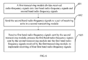
- an embodiment of the present invention provides a signal receiving method, as shown in FIG. 6 , where the method includes:
- a first transceiving module divides received radio-frequency signals into first band radio-frequency signals and second band radio-frequency signals.
- the first band radio-frequency signals include two signals in different polarization directions
- the second band radio-frequency signals include two signals in different polarization directions.
- 603 Receive first band radio-frequency signals sent by the second transceiving module, convert the first band radio-frequency signals sent by the second transceiving module and the foregoing first band radio-frequency signals received by the first transceiving module into intermediate-frequency signals, and process the intermediate-frequency signals, to implement receiving of four first band radio-frequency signals.
- the first band radio-frequency signals sent by the second transceiving module 2 are sent by a combining network in the second transceiving module 2 to a pair of receiving units in the first transceiving module 1.
- the second transceiving module 2 divides received radio-frequency signals into first band radio-frequency signals and second band radio-frequency signals, and sends the first band radio-frequency signals to the pair of receiving units in the first transceiving module 1 through the combining network in the second transceiving module 2.
- the first band radio-frequency signals sent by the second transceiving module 2 are sent by a co-antenna filter in the second transceiving module 2 to a pair of receiving units in the first transceiving module 1.
- the second transceiving module first divides received radio-frequency signals into fifth band radio-frequency signals and second band radio-frequency signals, divides the fifth band radio-frequency signals into first band radio-frequency signals and sixth band radio-frequency signals, and sends the first band radio-frequency signals to the pair of receiving units in the first transceiving module 1 through the co-antenna filter in the second transceiving module 2.
- the second transceiving module 2 may send the sixth band radio-frequency signals to a radio remote unit, for the radio remote unit to implement receiving of six band radio-frequency signals.
- the foregoing method may also include:
- the first transceiving module 1 divides received radio-frequency signals into first band radio-frequency signals and second band radio-frequency signals, sends the second band radio-frequency signals to the pair of receiving units in the transceiving module 2, for the second transceiving module 2 to implement receiving of four second band radio-frequency signals; meanwhile, the first transceiving module 1 receives first band radio-frequency signals sent by the second transceiving module 2, in combination with the first band radio-frequency signals received by the first transceiving module 1, to implement receiving of four first band radio-frequency signals; the second transceiving module 2 may divide received radio-frequency signals into first band radio-frequency signals and second band radio-frequency signals, and sends the first band radio-frequency signals to the pair of receiving units in the first transceiving module 1, for the first transceiving module 1 to implement receiving of four second band radio-frequency signals; the second transceiving module 2 may further receive the second band radio-frequency signals sent by the first transceiving module 1, in combination
- Another embodiment of the present invention provides a signal receiving method. Compared with the method provided by the foregoing embodiment, a difference lies in that step 602 is replaced with step 602'.
- 602' Divide the second band radio-frequency signals into third band radio-frequency signals and fourth band radio-frequency signals, and send the third band radio-frequency signals to a pair of receiving units in the second transceiving module.
- the first band radio-frequency signals sent by the second transceiving module 2 may be sent by a co-antenna filter in the second transceiving module 2 to a pair of receiving units in the first transceiving module 1.
- the second transceiving module 2 first divides received radio-frequency signals into fifth band radio-frequency signals and second band radio-frequency signals, where the second band radio-frequency signals include the third band radio-frequency signals, converts the third band radio-frequency signals sent by the first transceiving module 1 and the foregoing third band radio-frequency signals received by the second transceiving module into intermediate-frequency signals, and processes the intermediate-frequency signals, to implement receiving of four third band radio-frequency signals.
- the second transceiving module 2 may divide the fifth band radio-frequency signals into first band radio-frequency signals and sixth band radio-frequency signals, and sends the first band radio-frequency signals to the pair of receiving units in the first transceiving module 1 through the co-antenna filter in the second transceiving module 2. Further, the second transceiving module 2 may also send the sixth band radio-frequency signals to a radio remote unit, for the radio remote unit to implement receiving of six band radio-frequency signals.
- the method may further include:
- 604' Send the fourth band radio-frequency signals to the radio remote unit, for the radio remote unit to implement receiving of fourth band radio-frequency signals.
- the foregoing method may include:
- An embodiment of the present invention provides a base station, where the base station includes any antenna according to the foregoing embodiments. Receiving of four radio-frequency signals with more than one band may be implemented, and uplink network performance of a base station may be improved.
- An embodiment of the present invention provides a communication system, where the communication system includes the base station according to the foregoing embodiment.
- receiving of four dual-band signals is described in detail. It may be understood that, if more than one pair of receiving units, instead of only one pair of receiving units are provided in the foregoing embodiments, receiving of more than four dual-band signals may be implemented; if received radio-frequency signals are not only dual bands, by extending a corresponding co-element filter unit, combining-splitting network and transceiving unit arrays, receiving of radio-frequency signals with more than two bands may be implemented; if the combining network is not only combining of dual bands, but is extended to combining of more than two bands, a connection to multiple different RRUs or receiving of multiple bands of one RRU may be implemented.
- the method, the module, an apparatus and the system according to the embodiments of the present invention may also be used for transmitting more than four signals with more than two bands, where the proper changes may include but are not limited to utilizing a splitting function of the combining network, utilizing a combining function of the co-antenna filter, adding a transmitting channel, and so on.
- the second connection point of the co-antenna filter may be connected to an RRU, but the present invention is not limited to this, and the second connection point of the co-antenna filter may also be connected to a non-distributed base station.
- the combining network may also adopt a structure similar to that of the combining-splitting network.
- T signals which are received from the co-antenna filter unit and in one polarization direction are combined to from U signals.
- one pair of receiving units is changed to U pairs of receiving units, configured to receive the foregoing U signals.
- U and T are positive integers, and U is not greater than T.
- the combining network may be omitted.
- the co-antenna filter may adopt a structure which is similar to that of the co-element filter unit in which multiple filters are included.
- one combining-splitting network may be deployed to combine or divide signals, thereby implementing signal receiving and sending when the antenna element arrays are used as a passive antenna.
- each functional unit according to the embodiments of the present invention may be integrated into a processing unit, each unit may also exist independently and physically, and two or more than two units may also be integrated into a unit.
- the combing network and the co-antenna filter may be a processing unit, or the co-element filter, the combining-splitting network and the combining network may be a processing unit, which is not enumerated here.
- the functions When being implemented in the form of a software function unit and sold or used as a stand-alone product, the functions may be stored in a computer-readable storage medium. Based on such understanding, the essence of the technical solutions of the present invention, or part that makes contributions to the prior art, or part of the technical solutions may be embodied in the form of a software product.
- the computer software product may be stored in a storage medium, and includes several instructions for instructing a computer device (for example, which may be a personal computer, a server, or a network device) to execute all or part of the steps of the method in each embodiment of the present invention.
- the storage medium includes: any medium that is capable of storing program code, such as a U-disk, a removable hard disk, a read-only memory (ROM, Read-Only Memory), a random access memory (RAM, Random Access Memory), a magnetic disk, or an optical disk.
- program code such as a U-disk, a removable hard disk, a read-only memory (ROM, Read-Only Memory), a random access memory (RAM, Random Access Memory), a magnetic disk, or an optical disk.
Landscapes
- Engineering & Computer Science (AREA)
- Computer Networks & Wireless Communication (AREA)
- Signal Processing (AREA)
- Variable-Direction Aerials And Aerial Arrays (AREA)
- Transceivers (AREA)
- Radio Transmission System (AREA)
- Mobile Radio Communication Systems (AREA)
Applications Claiming Priority (1)
| Application Number | Priority Date | Filing Date | Title |
|---|---|---|---|
| PCT/CN2012/073494 WO2012103845A2 (fr) | 2012-04-01 | 2012-04-01 | Module émetteur-récepteur, antenne, station de base et procédé de réception de signal |
Publications (3)
| Publication Number | Publication Date |
|---|---|
| EP2822100A2 true EP2822100A2 (fr) | 2015-01-07 |
| EP2822100A4 EP2822100A4 (fr) | 2015-04-01 |
| EP2822100B1 EP2822100B1 (fr) | 2016-12-21 |
Family
ID=46603145
Family Applications (1)
| Application Number | Title | Priority Date | Filing Date |
|---|---|---|---|
| EP12741752.5A Active EP2822100B1 (fr) | 2012-04-01 | 2012-04-01 | Module émetteur-récepteur, antenne, station de base et procédé de réception de signal |
Country Status (8)
| Country | Link |
|---|---|
| US (1) | US9258050B2 (fr) |
| EP (1) | EP2822100B1 (fr) |
| JP (1) | JP5948669B2 (fr) |
| KR (1) | KR101621298B1 (fr) |
| CN (1) | CN102804504B (fr) |
| BR (1) | BR112014024540B1 (fr) |
| CA (1) | CA2868985C (fr) |
| WO (1) | WO2012103845A2 (fr) |
Cited By (1)
| Publication number | Priority date | Publication date | Assignee | Title |
|---|---|---|---|---|
| EP3703270A4 (fr) * | 2017-11-24 | 2020-10-21 | Huawei Technologies Co., Ltd. | Procédé de transmission de signal de liaison montante, station de base, et système |
Families Citing this family (3)
| Publication number | Priority date | Publication date | Assignee | Title |
|---|---|---|---|---|
| CN102104392B (zh) * | 2010-12-15 | 2013-10-09 | 华为技术有限公司 | 多频段多路收发设备及方法、基站系统 |
| TWI749867B (zh) * | 2020-11-12 | 2021-12-11 | 華碩電腦股份有限公司 | 無線收發裝置 |
| CN112333722A (zh) * | 2020-11-20 | 2021-02-05 | 深圳中时利和科技有限公司 | 一种基于nsa组织网的5g收发装置和方法 |
Citations (2)
| Publication number | Priority date | Publication date | Assignee | Title |
|---|---|---|---|---|
| WO2008020178A1 (fr) * | 2006-08-18 | 2008-02-21 | Quintel Technology Limited | Système d'antennes à réception simultanée avec une inclinaison électrique |
| US8090326B1 (en) * | 2010-12-13 | 2012-01-03 | Huawei Technologies Co., Ltd. | Communication signal transmission method, device, and system |
Family Cites Families (10)
| Publication number | Priority date | Publication date | Assignee | Title |
|---|---|---|---|---|
| JP3348506B2 (ja) * | 1994-03-16 | 2002-11-20 | 日産自動車株式会社 | 電話/gps共用平面型アンテナおよび電話/gps共用送受信装置 |
| AU1170201A (en) * | 1999-10-28 | 2001-05-08 | Celletra Ltd. | Cellular base station augmentation |
| JP3699883B2 (ja) | 2000-06-29 | 2005-09-28 | 松下電器産業株式会社 | 無線基地局装置及び無線通信方法 |
| US20020137472A1 (en) * | 2001-01-23 | 2002-09-26 | Quinn Liam B. | Wireless antenna switching system |
| JP4097918B2 (ja) * | 2001-05-24 | 2008-06-11 | ソフトバンクテレコム株式会社 | 基地局における移動通信方法、移動通信基地局装置および移動局装置 |
| GB0415811D0 (en) * | 2004-07-15 | 2004-08-18 | Quintel Technology Ltd | Antenna system for shared operation |
| CN101507128B (zh) | 2006-09-11 | 2012-10-10 | 松下电器产业株式会社 | 无线通信装置 |
| CN100464508C (zh) * | 2007-02-13 | 2009-02-25 | 华为技术有限公司 | 一种利用基站天线收发信号的方法和基站天线 |
| CN101072413A (zh) * | 2007-03-01 | 2007-11-14 | 中兴通讯股份有限公司 | 具有多路分集天线的移动终端 |
| CN102104392B (zh) | 2010-12-15 | 2013-10-09 | 华为技术有限公司 | 多频段多路收发设备及方法、基站系统 |
-
2012
- 2012-04-01 BR BR112014024540-1A patent/BR112014024540B1/pt active IP Right Grant
- 2012-04-01 KR KR1020147029651A patent/KR101621298B1/ko active IP Right Grant
- 2012-04-01 WO PCT/CN2012/073494 patent/WO2012103845A2/fr active Application Filing
- 2012-04-01 CA CA2868985A patent/CA2868985C/fr active Active
- 2012-04-01 JP JP2015502052A patent/JP5948669B2/ja active Active
- 2012-04-01 CN CN201280000854.9A patent/CN102804504B/zh active Active
- 2012-04-01 EP EP12741752.5A patent/EP2822100B1/fr active Active
-
2014
- 2014-09-30 US US14/502,179 patent/US9258050B2/en active Active
Patent Citations (2)
| Publication number | Priority date | Publication date | Assignee | Title |
|---|---|---|---|---|
| WO2008020178A1 (fr) * | 2006-08-18 | 2008-02-21 | Quintel Technology Limited | Système d'antennes à réception simultanée avec une inclinaison électrique |
| US8090326B1 (en) * | 2010-12-13 | 2012-01-03 | Huawei Technologies Co., Ltd. | Communication signal transmission method, device, and system |
Non-Patent Citations (1)
| Title |
|---|
| See also references of WO2012103845A2 * |
Cited By (2)
| Publication number | Priority date | Publication date | Assignee | Title |
|---|---|---|---|---|
| EP3703270A4 (fr) * | 2017-11-24 | 2020-10-21 | Huawei Technologies Co., Ltd. | Procédé de transmission de signal de liaison montante, station de base, et système |
| US11284425B2 (en) | 2017-11-24 | 2022-03-22 | Huawei Technologies Co., Ltd. | Uplink signal transmission method and system, and base station |
Also Published As
| Publication number | Publication date |
|---|---|
| EP2822100A4 (fr) | 2015-04-01 |
| BR112014024540B1 (pt) | 2019-11-12 |
| CN102804504A (zh) | 2012-11-28 |
| CA2868985A1 (fr) | 2012-08-09 |
| US20150017920A1 (en) | 2015-01-15 |
| KR20140139047A (ko) | 2014-12-04 |
| CN102804504B (zh) | 2014-11-05 |
| KR101621298B1 (ko) | 2016-05-16 |
| JP5948669B2 (ja) | 2016-07-06 |
| WO2012103845A3 (fr) | 2013-03-07 |
| EP2822100B1 (fr) | 2016-12-21 |
| US9258050B2 (en) | 2016-02-09 |
| CA2868985C (fr) | 2016-11-08 |
| WO2012103845A2 (fr) | 2012-08-09 |
| JP2015518669A (ja) | 2015-07-02 |
Similar Documents
| Publication | Publication Date | Title |
|---|---|---|
| US8786493B2 (en) | Antenna system with a beam with an adjustable tilt | |
| US20170019847A1 (en) | Multichannel radio frequency apparatus and method | |
| US8588856B2 (en) | Antenna system and base station system | |
| JP5603950B2 (ja) | アンテナ素子の多重化方法および多重化装置、ならびにアンテナ構成要素 | |
| US9992757B2 (en) | Donor unit, remote unit, and mobile communication base station system having same | |
| EP3220553A1 (fr) | Antenne et système d'antenne active | |
| CN108092698B (zh) | 一种波束训练方法及装置 | |
| US9258050B2 (en) | Transceiving module, antenna, base station and signal receiving method | |
| CN106559110B (zh) | 有源天线、载波聚合方法和系统 | |
| EP3131214B1 (fr) | Multiplexeur, station de base, système multiplexeur de signaux et procédé d'émission de signaux | |
| CN112583455B (zh) | 一种信号处理方法以及基站 | |
| US20170214152A1 (en) | Active Dual Antenna Arrangement | |
| CN106605445B (zh) | 射频拉远单元、接收机和基站 | |
| WO2022206520A1 (fr) | Procédé et appareil de transfert de signal | |
| RU2543515C2 (ru) | Способ, устройство и система передачи сигнала связи | |
| CN114340049B (zh) | Poi设备和无线覆盖系统 | |
| CN115398816A (zh) | 用于模拟波束转向的方法和发射机 | |
| US20230352833A1 (en) | Feed network, antenna, antenna system, base station and beam forming method | |
| JP2022515510A (ja) | 信号処理装置および方法、ならびにアクセスネットワークデバイス | |
| RU2575049C1 (ru) | Антенная система, система базовой станции и система связи | |
| WO2017000228A1 (fr) | Dispositif et procédé de traitement de porteuse sur la base de mise en réseau dans un même canal | |
| KR102250111B1 (ko) | 분산 안테나 시스템의 헤드엔드 장치 및 이의 동작 방법 |
Legal Events
| Date | Code | Title | Description |
|---|---|---|---|
| PUAI | Public reference made under article 153(3) epc to a published international application that has entered the european phase |
Free format text: ORIGINAL CODE: 0009012 |
|
| 17P | Request for examination filed |
Effective date: 20141002 |
|
| AK | Designated contracting states |
Kind code of ref document: A2 Designated state(s): AL AT BE BG CH CY CZ DE DK EE ES FI FR GB GR HR HU IE IS IT LI LT LU LV MC MK MT NL NO PL PT RO RS SE SI SK SM TR |
|
| AX | Request for extension of the european patent |
Extension state: BA ME |
|
| A4 | Supplementary search report drawn up and despatched |
Effective date: 20150226 |
|
| RIC1 | Information provided on ipc code assigned before grant |
Ipc: H01Q 23/00 20060101AFI20150220BHEP |
|
| DAX | Request for extension of the european patent (deleted) | ||
| 17Q | First examination report despatched |
Effective date: 20160120 |
|
| GRAP | Despatch of communication of intention to grant a patent |
Free format text: ORIGINAL CODE: EPIDOSNIGR1 |
|
| INTG | Intention to grant announced |
Effective date: 20160701 |
|
| GRAS | Grant fee paid |
Free format text: ORIGINAL CODE: EPIDOSNIGR3 |
|
| GRAA | (expected) grant |
Free format text: ORIGINAL CODE: 0009210 |
|
| AK | Designated contracting states |
Kind code of ref document: B1 Designated state(s): AL AT BE BG CH CY CZ DE DK EE ES FI FR GB GR HR HU IE IS IT LI LT LU LV MC MK MT NL NO PL PT RO RS SE SI SK SM TR |
|
| REG | Reference to a national code |
Ref country code: GB Ref legal event code: FG4D |
|
| REG | Reference to a national code |
Ref country code: CH Ref legal event code: EP |
|
| REG | Reference to a national code |
Ref country code: IE Ref legal event code: FG4D |
|
| REG | Reference to a national code |
Ref country code: AT Ref legal event code: REF Ref document number: 856214 Country of ref document: AT Kind code of ref document: T Effective date: 20170115 |
|
| REG | Reference to a national code |
Ref country code: DE Ref legal event code: R096 Ref document number: 602012026843 Country of ref document: DE |
|
| PG25 | Lapsed in a contracting state [announced via postgrant information from national office to epo] |
Ref country code: LV Free format text: LAPSE BECAUSE OF FAILURE TO SUBMIT A TRANSLATION OF THE DESCRIPTION OR TO PAY THE FEE WITHIN THE PRESCRIBED TIME-LIMIT Effective date: 20161221 |
|
| REG | Reference to a national code |
Ref country code: LT Ref legal event code: MG4D |
|
| REG | Reference to a national code |
Ref country code: NL Ref legal event code: MP Effective date: 20161221 |
|
| PG25 | Lapsed in a contracting state [announced via postgrant information from national office to epo] |
Ref country code: SE Free format text: LAPSE BECAUSE OF FAILURE TO SUBMIT A TRANSLATION OF THE DESCRIPTION OR TO PAY THE FEE WITHIN THE PRESCRIBED TIME-LIMIT Effective date: 20161221 Ref country code: LT Free format text: LAPSE BECAUSE OF FAILURE TO SUBMIT A TRANSLATION OF THE DESCRIPTION OR TO PAY THE FEE WITHIN THE PRESCRIBED TIME-LIMIT Effective date: 20161221 Ref country code: GR Free format text: LAPSE BECAUSE OF FAILURE TO SUBMIT A TRANSLATION OF THE DESCRIPTION OR TO PAY THE FEE WITHIN THE PRESCRIBED TIME-LIMIT Effective date: 20170322 Ref country code: NO Free format text: LAPSE BECAUSE OF FAILURE TO SUBMIT A TRANSLATION OF THE DESCRIPTION OR TO PAY THE FEE WITHIN THE PRESCRIBED TIME-LIMIT Effective date: 20170321 |
|
| REG | Reference to a national code |
Ref country code: AT Ref legal event code: MK05 Ref document number: 856214 Country of ref document: AT Kind code of ref document: T Effective date: 20161221 |
|
| PG25 | Lapsed in a contracting state [announced via postgrant information from national office to epo] |
Ref country code: RS Free format text: LAPSE BECAUSE OF FAILURE TO SUBMIT A TRANSLATION OF THE DESCRIPTION OR TO PAY THE FEE WITHIN THE PRESCRIBED TIME-LIMIT Effective date: 20161221 Ref country code: HR Free format text: LAPSE BECAUSE OF FAILURE TO SUBMIT A TRANSLATION OF THE DESCRIPTION OR TO PAY THE FEE WITHIN THE PRESCRIBED TIME-LIMIT Effective date: 20161221 Ref country code: FI Free format text: LAPSE BECAUSE OF FAILURE TO SUBMIT A TRANSLATION OF THE DESCRIPTION OR TO PAY THE FEE WITHIN THE PRESCRIBED TIME-LIMIT Effective date: 20161221 |
|
| PG25 | Lapsed in a contracting state [announced via postgrant information from national office to epo] |
Ref country code: NL Free format text: LAPSE BECAUSE OF FAILURE TO SUBMIT A TRANSLATION OF THE DESCRIPTION OR TO PAY THE FEE WITHIN THE PRESCRIBED TIME-LIMIT Effective date: 20161221 |
|
| PG25 | Lapsed in a contracting state [announced via postgrant information from national office to epo] |
Ref country code: RO Free format text: LAPSE BECAUSE OF FAILURE TO SUBMIT A TRANSLATION OF THE DESCRIPTION OR TO PAY THE FEE WITHIN THE PRESCRIBED TIME-LIMIT Effective date: 20161221 Ref country code: CZ Free format text: LAPSE BECAUSE OF FAILURE TO SUBMIT A TRANSLATION OF THE DESCRIPTION OR TO PAY THE FEE WITHIN THE PRESCRIBED TIME-LIMIT Effective date: 20161221 Ref country code: SK Free format text: LAPSE BECAUSE OF FAILURE TO SUBMIT A TRANSLATION OF THE DESCRIPTION OR TO PAY THE FEE WITHIN THE PRESCRIBED TIME-LIMIT Effective date: 20161221 Ref country code: IS Free format text: LAPSE BECAUSE OF FAILURE TO SUBMIT A TRANSLATION OF THE DESCRIPTION OR TO PAY THE FEE WITHIN THE PRESCRIBED TIME-LIMIT Effective date: 20170421 Ref country code: EE Free format text: LAPSE BECAUSE OF FAILURE TO SUBMIT A TRANSLATION OF THE DESCRIPTION OR TO PAY THE FEE WITHIN THE PRESCRIBED TIME-LIMIT Effective date: 20161221 |
|
| PG25 | Lapsed in a contracting state [announced via postgrant information from national office to epo] |
Ref country code: BG Free format text: LAPSE BECAUSE OF FAILURE TO SUBMIT A TRANSLATION OF THE DESCRIPTION OR TO PAY THE FEE WITHIN THE PRESCRIBED TIME-LIMIT Effective date: 20170321 Ref country code: SM Free format text: LAPSE BECAUSE OF FAILURE TO SUBMIT A TRANSLATION OF THE DESCRIPTION OR TO PAY THE FEE WITHIN THE PRESCRIBED TIME-LIMIT Effective date: 20161221 Ref country code: PL Free format text: LAPSE BECAUSE OF FAILURE TO SUBMIT A TRANSLATION OF THE DESCRIPTION OR TO PAY THE FEE WITHIN THE PRESCRIBED TIME-LIMIT Effective date: 20161221 Ref country code: AT Free format text: LAPSE BECAUSE OF FAILURE TO SUBMIT A TRANSLATION OF THE DESCRIPTION OR TO PAY THE FEE WITHIN THE PRESCRIBED TIME-LIMIT Effective date: 20161221 Ref country code: BE Free format text: LAPSE BECAUSE OF FAILURE TO SUBMIT A TRANSLATION OF THE DESCRIPTION OR TO PAY THE FEE WITHIN THE PRESCRIBED TIME-LIMIT Effective date: 20161221 Ref country code: ES Free format text: LAPSE BECAUSE OF FAILURE TO SUBMIT A TRANSLATION OF THE DESCRIPTION OR TO PAY THE FEE WITHIN THE PRESCRIBED TIME-LIMIT Effective date: 20161221 Ref country code: PT Free format text: LAPSE BECAUSE OF FAILURE TO SUBMIT A TRANSLATION OF THE DESCRIPTION OR TO PAY THE FEE WITHIN THE PRESCRIBED TIME-LIMIT Effective date: 20170421 |
|
| REG | Reference to a national code |
Ref country code: DE Ref legal event code: R097 Ref document number: 602012026843 Country of ref document: DE |
|
| PLBE | No opposition filed within time limit |
Free format text: ORIGINAL CODE: 0009261 |
|
| STAA | Information on the status of an ep patent application or granted ep patent |
Free format text: STATUS: NO OPPOSITION FILED WITHIN TIME LIMIT |
|
| 26N | No opposition filed |
Effective date: 20170922 |
|
| PG25 | Lapsed in a contracting state [announced via postgrant information from national office to epo] |
Ref country code: DK Free format text: LAPSE BECAUSE OF FAILURE TO SUBMIT A TRANSLATION OF THE DESCRIPTION OR TO PAY THE FEE WITHIN THE PRESCRIBED TIME-LIMIT Effective date: 20161221 |
|
| REG | Reference to a national code |
Ref country code: CH Ref legal event code: PL |
|
| REG | Reference to a national code |
Ref country code: IE Ref legal event code: MM4A |
|
| REG | Reference to a national code |
Ref country code: FR Ref legal event code: ST Effective date: 20171229 |
|
| PG25 | Lapsed in a contracting state [announced via postgrant information from national office to epo] |
Ref country code: FR Free format text: LAPSE BECAUSE OF NON-PAYMENT OF DUE FEES Effective date: 20170502 Ref country code: MC Free format text: LAPSE BECAUSE OF FAILURE TO SUBMIT A TRANSLATION OF THE DESCRIPTION OR TO PAY THE FEE WITHIN THE PRESCRIBED TIME-LIMIT Effective date: 20161221 |
|
| PG25 | Lapsed in a contracting state [announced via postgrant information from national office to epo] |
Ref country code: CH Free format text: LAPSE BECAUSE OF NON-PAYMENT OF DUE FEES Effective date: 20170430 Ref country code: LI Free format text: LAPSE BECAUSE OF NON-PAYMENT OF DUE FEES Effective date: 20170430 Ref country code: LU Free format text: LAPSE BECAUSE OF NON-PAYMENT OF DUE FEES Effective date: 20170401 Ref country code: SI Free format text: LAPSE BECAUSE OF FAILURE TO SUBMIT A TRANSLATION OF THE DESCRIPTION OR TO PAY THE FEE WITHIN THE PRESCRIBED TIME-LIMIT Effective date: 20161221 |
|
| PG25 | Lapsed in a contracting state [announced via postgrant information from national office to epo] |
Ref country code: IE Free format text: LAPSE BECAUSE OF NON-PAYMENT OF DUE FEES Effective date: 20170401 |
|
| PG25 | Lapsed in a contracting state [announced via postgrant information from national office to epo] |
Ref country code: MT Free format text: LAPSE BECAUSE OF NON-PAYMENT OF DUE FEES Effective date: 20170401 |
|
| PG25 | Lapsed in a contracting state [announced via postgrant information from national office to epo] |
Ref country code: HU Free format text: LAPSE BECAUSE OF FAILURE TO SUBMIT A TRANSLATION OF THE DESCRIPTION OR TO PAY THE FEE WITHIN THE PRESCRIBED TIME-LIMIT; INVALID AB INITIO Effective date: 20120401 |
|
| PG25 | Lapsed in a contracting state [announced via postgrant information from national office to epo] |
Ref country code: CY Free format text: LAPSE BECAUSE OF FAILURE TO SUBMIT A TRANSLATION OF THE DESCRIPTION OR TO PAY THE FEE WITHIN THE PRESCRIBED TIME-LIMIT Effective date: 20161221 |
|
| PG25 | Lapsed in a contracting state [announced via postgrant information from national office to epo] |
Ref country code: MK Free format text: LAPSE BECAUSE OF FAILURE TO SUBMIT A TRANSLATION OF THE DESCRIPTION OR TO PAY THE FEE WITHIN THE PRESCRIBED TIME-LIMIT Effective date: 20161221 |
|
| PG25 | Lapsed in a contracting state [announced via postgrant information from national office to epo] |
Ref country code: TR Free format text: LAPSE BECAUSE OF FAILURE TO SUBMIT A TRANSLATION OF THE DESCRIPTION OR TO PAY THE FEE WITHIN THE PRESCRIBED TIME-LIMIT Effective date: 20161221 |
|
| PG25 | Lapsed in a contracting state [announced via postgrant information from national office to epo] |
Ref country code: AL Free format text: LAPSE BECAUSE OF FAILURE TO SUBMIT A TRANSLATION OF THE DESCRIPTION OR TO PAY THE FEE WITHIN THE PRESCRIBED TIME-LIMIT Effective date: 20161221 |
|
| PGFP | Annual fee paid to national office [announced via postgrant information from national office to epo] |
Ref country code: IT Payment date: 20230310 Year of fee payment: 12 |
|
| PGFP | Annual fee paid to national office [announced via postgrant information from national office to epo] |
Ref country code: DE Payment date: 20230307 Year of fee payment: 12 |
|
| PGFP | Annual fee paid to national office [announced via postgrant information from national office to epo] |
Ref country code: GB Payment date: 20240229 Year of fee payment: 13 |