EP2821772A1 - Die-cast product rigidity evaluation method and die-cast product - Google Patents
Die-cast product rigidity evaluation method and die-cast product Download PDFInfo
- Publication number
- EP2821772A1 EP2821772A1 EP20120870021 EP12870021A EP2821772A1 EP 2821772 A1 EP2821772 A1 EP 2821772A1 EP 20120870021 EP20120870021 EP 20120870021 EP 12870021 A EP12870021 A EP 12870021A EP 2821772 A1 EP2821772 A1 EP 2821772A1
- Authority
- EP
- European Patent Office
- Prior art keywords
- die casting
- casting product
- strength
- defect
- evaluation method
- Prior art date
- Legal status (The legal status is an assumption and is not a legal conclusion. Google has not performed a legal analysis and makes no representation as to the accuracy of the status listed.)
- Withdrawn
Links
- 238000011156 evaluation Methods 0.000 title claims abstract description 78
- 238000004512 die casting Methods 0.000 claims abstract description 144
- 230000007547 defect Effects 0.000 claims abstract description 119
- 238000001514 detection method Methods 0.000 claims abstract description 67
- 238000012360 testing method Methods 0.000 claims abstract description 31
- 238000005266 casting Methods 0.000 claims abstract description 26
- 238000004458 analytical method Methods 0.000 claims abstract description 11
- 229910052782 aluminium Inorganic materials 0.000 claims description 41
- XAGFODPZIPBFFR-UHFFFAOYSA-N aluminium Chemical group [Al] XAGFODPZIPBFFR-UHFFFAOYSA-N 0.000 claims description 41
- 238000004364 calculation method Methods 0.000 claims description 16
- 238000000034 method Methods 0.000 claims description 14
- 238000010586 diagram Methods 0.000 description 19
- 230000000052 comparative effect Effects 0.000 description 15
- 238000007689 inspection Methods 0.000 description 10
- 238000009826 distribution Methods 0.000 description 5
- 238000005259 measurement Methods 0.000 description 5
- 238000010191 image analysis Methods 0.000 description 4
- 230000005540 biological transmission Effects 0.000 description 3
- 238000002591 computed tomography Methods 0.000 description 3
- 230000001066 destructive effect Effects 0.000 description 3
- 239000000523 sample Substances 0.000 description 3
- 229910000838 Al alloy Inorganic materials 0.000 description 2
- 229910018594 Si-Cu Inorganic materials 0.000 description 2
- 229910008465 Si—Cu Inorganic materials 0.000 description 2
- 238000002592 echocardiography Methods 0.000 description 2
- 238000005470 impregnation Methods 0.000 description 2
- 230000005389 magnetism Effects 0.000 description 2
- 238000012986 modification Methods 0.000 description 2
- 230000004048 modification Effects 0.000 description 2
- 230000005855 radiation Effects 0.000 description 2
- 238000004904 shortening Methods 0.000 description 2
- FYYHWMGAXLPEAU-UHFFFAOYSA-N Magnesium Chemical compound [Mg] FYYHWMGAXLPEAU-UHFFFAOYSA-N 0.000 description 1
- 230000005856 abnormality Effects 0.000 description 1
- 238000005299 abrasion Methods 0.000 description 1
- 235000015895 biscuits Nutrition 0.000 description 1
- 230000007797 corrosion Effects 0.000 description 1
- 238000005260 corrosion Methods 0.000 description 1
- 239000006185 dispersion Substances 0.000 description 1
- 230000000694 effects Effects 0.000 description 1
- 239000000314 lubricant Substances 0.000 description 1
- 229910052749 magnesium Inorganic materials 0.000 description 1
- 239000011777 magnesium Substances 0.000 description 1
- 238000012423 maintenance Methods 0.000 description 1
- 238000004519 manufacturing process Methods 0.000 description 1
- 238000000691 measurement method Methods 0.000 description 1
- 239000000155 melt Substances 0.000 description 1
- 229910052751 metal Inorganic materials 0.000 description 1
- 239000002184 metal Substances 0.000 description 1
- 238000001000 micrograph Methods 0.000 description 1
- 239000000203 mixture Substances 0.000 description 1
- 230000003287 optical effect Effects 0.000 description 1
- 230000001105 regulatory effect Effects 0.000 description 1
- 230000035945 sensitivity Effects 0.000 description 1
- 239000007787 solid Substances 0.000 description 1
- 238000010998 test method Methods 0.000 description 1
- 238000012795 verification Methods 0.000 description 1
Images



Classifications
-
- G—PHYSICS
- G01—MEASURING; TESTING
- G01N—INVESTIGATING OR ANALYSING MATERIALS BY DETERMINING THEIR CHEMICAL OR PHYSICAL PROPERTIES
- G01N3/00—Investigating strength properties of solid materials by application of mechanical stress
- G01N3/22—Investigating strength properties of solid materials by application of mechanical stress by applying steady torsional forces
-
- B—PERFORMING OPERATIONS; TRANSPORTING
- B22—CASTING; POWDER METALLURGY
- B22C—FOUNDRY MOULDING
- B22C19/00—Components or accessories for moulding machines
- B22C19/04—Controlling devices specially designed for moulding machines
-
- B—PERFORMING OPERATIONS; TRANSPORTING
- B22—CASTING; POWDER METALLURGY
- B22C—FOUNDRY MOULDING
- B22C9/00—Moulds or cores; Moulding processes
- B22C9/22—Moulds for peculiarly-shaped castings
- B22C9/24—Moulds for peculiarly-shaped castings for hollow articles
-
- B—PERFORMING OPERATIONS; TRANSPORTING
- B22—CASTING; POWDER METALLURGY
- B22D—CASTING OF METALS; CASTING OF OTHER SUBSTANCES BY THE SAME PROCESSES OR DEVICES
- B22D17/00—Pressure die casting or injection die casting, i.e. casting in which the metal is forced into a mould under high pressure
-
- B—PERFORMING OPERATIONS; TRANSPORTING
- B60—VEHICLES IN GENERAL
- B60R—VEHICLES, VEHICLE FITTINGS, OR VEHICLE PARTS, NOT OTHERWISE PROVIDED FOR
- B60R25/00—Fittings or systems for preventing or indicating unauthorised use or theft of vehicles
- B60R25/01—Fittings or systems for preventing or indicating unauthorised use or theft of vehicles operating on vehicle systems or fittings, e.g. on doors, seats or windscreens
- B60R25/02—Fittings or systems for preventing or indicating unauthorised use or theft of vehicles operating on vehicle systems or fittings, e.g. on doors, seats or windscreens operating on the steering mechanism
- B60R25/021—Fittings or systems for preventing or indicating unauthorised use or theft of vehicles operating on vehicle systems or fittings, e.g. on doors, seats or windscreens operating on the steering mechanism restraining movement of the steering column or steering wheel hub, e.g. restraining means controlled by ignition switch
- B60R25/0211—Fittings or systems for preventing or indicating unauthorised use or theft of vehicles operating on vehicle systems or fittings, e.g. on doors, seats or windscreens operating on the steering mechanism restraining movement of the steering column or steering wheel hub, e.g. restraining means controlled by ignition switch comprising a locking member radially and linearly moved towards the steering column
- B60R25/02115—Fittings or systems for preventing or indicating unauthorised use or theft of vehicles operating on vehicle systems or fittings, e.g. on doors, seats or windscreens operating on the steering mechanism restraining movement of the steering column or steering wheel hub, e.g. restraining means controlled by ignition switch comprising a locking member radially and linearly moved towards the steering column key actuated
-
- E—FIXED CONSTRUCTIONS
- E05—LOCKS; KEYS; WINDOW OR DOOR FITTINGS; SAFES
- E05B—LOCKS; ACCESSORIES THEREFOR; HANDCUFFS
- E05B15/00—Other details of locks; Parts for engagement by bolts of fastening devices
- E05B15/16—Use of special materials for parts of locks
- E05B15/1614—Use of special materials for parts of locks of hard materials, to prevent drilling
-
- G—PHYSICS
- G01—MEASURING; TESTING
- G01N—INVESTIGATING OR ANALYSING MATERIALS BY DETERMINING THEIR CHEMICAL OR PHYSICAL PROPERTIES
- G01N29/00—Investigating or analysing materials by the use of ultrasonic, sonic or infrasonic waves; Visualisation of the interior of objects by transmitting ultrasonic or sonic waves through the object
- G01N29/04—Analysing solids
- G01N29/11—Analysing solids by measuring attenuation of acoustic waves
-
- G—PHYSICS
- G01—MEASURING; TESTING
- G01N—INVESTIGATING OR ANALYSING MATERIALS BY DETERMINING THEIR CHEMICAL OR PHYSICAL PROPERTIES
- G01N2203/00—Investigating strength properties of solid materials by application of mechanical stress
- G01N2203/0058—Kind of property studied
- G01N2203/006—Crack, flaws, fracture or rupture
- G01N2203/0067—Fracture or rupture
-
- G—PHYSICS
- G01—MEASURING; TESTING
- G01N—INVESTIGATING OR ANALYSING MATERIALS BY DETERMINING THEIR CHEMICAL OR PHYSICAL PROPERTIES
- G01N2291/00—Indexing codes associated with group G01N29/00
- G01N2291/02—Indexing codes associated with the analysed material
- G01N2291/023—Solids
- G01N2291/0234—Metals, e.g. steel
-
- G—PHYSICS
- G01—MEASURING; TESTING
- G01N—INVESTIGATING OR ANALYSING MATERIALS BY DETERMINING THEIR CHEMICAL OR PHYSICAL PROPERTIES
- G01N2291/00—Indexing codes associated with group G01N29/00
- G01N2291/02—Indexing codes associated with the analysed material
- G01N2291/028—Material parameters
- G01N2291/02827—Elastic parameters, strength or force
-
- G—PHYSICS
- G01—MEASURING; TESTING
- G01N—INVESTIGATING OR ANALYSING MATERIALS BY DETERMINING THEIR CHEMICAL OR PHYSICAL PROPERTIES
- G01N2291/00—Indexing codes associated with group G01N29/00
- G01N2291/04—Wave modes and trajectories
- G01N2291/044—Internal reflections (echoes), e.g. on walls or defects
Definitions
- the present invention relates to a strength evaluation method of a die casting product, and a die casting product used in an electric power steering device of a vehicle (for example, a column housing made of an aluminum die casting).
- a steering column that serves as a main body and an attachment part of the steering lock device used in this manner is required to be solid and not to be easily broaken.
- JIS D5812 or the like regulates that no functional abnormality occur even when a torque of 200 Nm is applied to a steering shaft in a state where the steering shaft is locked.
- the steering column is made of a die casting of a light metal such as aluminum or magnesium, for example. Accordingly, an internal defect occurs in the steering column, and thus, if excessive torque is applied, there is a fear that the steering column may be broken. Thus, it is important how to evaluate the strength.
- PTLs 1 to 3 disclose the following techniques.
- PTL 1 discloses a technique in which a mixture of a component (Pb) that is easily detected by cold flakes detection apparatus that employs radiation, magnetism, ultrasonic waves or the like and a sleeve lubricant is coated on the inner surface of a sleeve and the detection sensitivity of cold flakes increases as Pb enters the cold flakes and a cavity.
- a component Pb
- PTL 2 discloses a technique that obtains dispersion information on cold flakes in a non-destructive state using a measurement method in which ultrasonic flaw detection and X-ray CT scanning are combined.
- ultrasonic waves are irradiated onto an aluminum die casting product, and a blow hole and cold flakes of the aluminum die casting product are detected based on information on sound waves from the aluminum die casting product to obtain first internal defect three-dimensional distribution data.
- the aluminum die casting product is measured by the X-ray CT scanning, and the blow hole of the aluminum die casting product is detected from plural cross-sectional images of the aluminum die casting product to obtain second internal defect three-dimensional distribution data. Then, the first internal defect three-dimensional distribution data and the second internal defect three-dimensional distribution data are compared with each other to obtain three-dimensional distribution data on the cold flakes of the aluminum die casting product.
- PTL 3 discloses a simple cold flakes inspection method in which a test piece cut out of a runner portion is abraded and corroded and an area ratio of cold flakes is then calculated based on observation of the cold flakes.
- PTL 4 discloses a technique in which ultrasonic flaw detection is performed for an aluminum die casting product having a complex member therein and a distance from a front surface to the complex member, an impregnation state of aluminum melt with respect to the complex member, a breakage state and the like are measured to determine whether the aluminum die casting product is good or bad.
- the technique disclosed in PTL 1 has an advantage in that a non-destructive inspection is available, but since it is necessary to perform an inspection using a special apparatus that employs radiation, magnetism, ultrasonic waves or the like after casting, operation time becomes long. Further, it is difficult to perform the strength evaluation in a casting site. Furthermore, since the accuracy of measurement and detection is not sufficient, it is difficult to perform the strength evaluation with high accuracy.
- the technique disclosed in PTL 2 has an advantage in that a non-destructive inspection is available, but since it is necessary to perform an inspection using a special apparatus for ultrasonic flaw detection or CT scanning after casting, operation time becomes long. Further, it is difficult to perform the strength evaluation in a casting site. Furthermore, since the accuracy of measurement and detection is not sufficient, it is difficult to perform the strength evaluation with high accuracy.
- the technique disclosed in PTL 3 has an advantage in that a special inspection apparatus is not necessary, but since the abrasion and corrosion are necessary, operation time becomes long. Further, since the test piece is cut out of the runner portion instead of a product, it is difficult to perform the strength evaluation with high accuracy.
- the strength evaluation method of the aluminum die casting product disclosed in PTL 4 can perform only the measurement of the impregnation state or the breakage with respect to the aluminum die casting product having the complex member therein, but cannot evaluate the strength of an aluminum die casting product having no complex member.
- the strength evaluation method of the aluminum die casting product disclosed in PTL 2 can perform the evaluation of an aluminum die casting product having no complex member.
- the aluminum die casting product has a complicated shape, and thus, it is difficult to detect the internal defect by ultrasonic flaw detection, for example.
- an obj ect of the invention is to provide a strength evaluation method of a die casting product capable of shortening operation time, performing a strength evaluation (strength guarantee) at a casting site and performing the strength evaluation with high accuracy, and such a die casting product.
- Another object of the invention is to provide a strength evaluation method of a die casting product capable of appropriately evaluating the strength of an actual die casting product and obtaining a die casting product having a predetermined strength, and such a die casting product.
- a strength evaluation method of a die casting product comprising: a casting step of casting a die casting product; a breakage step of performing a breakage test of the die casting product after casting; a strength reduction ratio calculation step of measuring an area ratio of cold flakes present in a broken surface of the die casting product in the breakage step, and obtaining a strength reduction ratio from the relationship between a torsional breakage torque value in the breakage step and the area ratio; and a strength evaluation area ratio calculation step of calculating a threshold value of -3 ⁇ ( ⁇ is a standard deviation) using the strength reduction ratio as an average value, and calculating a strength evaluation area ratio of the die casting product from the threshold value and a predetermined strength range.
- the casting step be a casting step based on JIS D5812
- the die casting product be an aluminum column housing
- the breakage test be a torsion test for the die casting product.
- the die casting product be used in a steering lock provided with an ignition switch for vehicle steering.
- a column housing made of an aluminum die casting in which the strength is evaluated by the strength evaluation method of the die casting product described above, in which the column housing made of an aluminum die casting is formed with a hole for the steering lock, and an area ratio of cold flakes in the area of a broken surface ranged up to a stress of 1/2 of a maximum value of stress acting on a breakage starting point, calculated by stress analysis from the breakage starting point when the hole for the steering lock is broken by the torsion test, is less than 10%.
- a strength evaluation method of a die casting product comprising: performing, with respect to a high stress portion obtained by performing stress analysis for the die casting product in advance, ultrasonic flaw detection for an internal defect in a predetermined range of the high stress portion; and evaluating that the die casting product has a predetermined strength when a defect ratio obtained by dividing a total area of the internal defect in the predetermined range by a total defect detection area is less than or equal to a predetermined value.
- the predetermined range of the high stress portion be a stress range of 50% or greater of a maximum stress of the high stress portion.
- a die casting product in which the strength is evaluated by the strength evaluation method of the die casting product described above, in which the defect ratio is 0.5% or less.
- the die casting product be a column housing used in an electric power steering device of a vehicle, and the high stress portion is a key lock portion of the column housing
- the embodiment of the invention it is possible to provide a strength evaluation method of a die casting product capable of shortening operation time, performing a strength evaluation at a casting site whenever necessary and performing the strength evaluation with high accuracy, and such a die casting product. Further, according to the strength evaluation method of a die casting product according to the embodiment of the invention, since ultrasonic flaw detection is performed for an internal defect in a predetermined range of the high stress portion with respect to a high stress portion obtained by performing stress analysis for the die casting product in advance; and the die casting product is evaluated to have a predetermined strength when a defect ratio obtained by dividing a total area of the internal defect in the predetermined range by a total defect detection area is less than or equal to a predetermined value, it is possible to appropriately evaluate the strength of an actual die casting product
- the predetermined range of the high stress portion is a stress range of 50% or greater of a maximum stress of the high stress portion, it is possible to more appropriately evaluate the strength of the die casting product.
- the die casting product according to the embodiment of the invention by evaluating the strength by the strength evaluation method of the die casting product according to the embodiment of the invention, and by setting a defect ratio obtained by dividing a total area of the internal defect in the predetermined range of the high stress portion by a total defect detection area to be 0.5% or less, it is possible to obtain a die casting product having a predetermined strength.
- the strength evaluation method of the present embodiment includes a casting step (S1), a breakage step (S2), a strength reduction ratio calculation step (S3), and a strength evaluation area ratio calculation step (S4).
- the casting step in the present embodiment refers to a step of performing die casting using ADC12 that is an Al-Si-Cu based aluminum alloy of JIS H5302, for example. It is preferable that a die casting product obtained in this step be a steering column housing 3 of an automobile steering device shown in FIG. 2 .
- the breakage step in the present embodiment refers to a step of performing a breakage test in a casting site for the die casting product obtained in the above-described casting step. It is preferable that the breakage test be a torsion test.
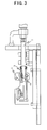
- a key lock jig 1 screw-coupled with the steering column housing (die casting product) 3 includes a convex key that protrudes from a key hole portion of the steering column housing 3 toward the inner diameter of the steering column housing 3. Further, a concave portion that is engaged with the key is formed in a torque transmission shaft 2. Torque transmits from the torque transmission shaft 2 to the key seat portion 4 of the steering column housing 3 through the convex key of the key lock jig 1, and causes the steering column housing to be broken using a corner portion of the key seat portion 4 as a starting point.
- the strength reduction ratio calculation step refers to a step of measuring an area ratio of cold flakes in a broken surface of the die casting product in the breakage step and calculating a strength reduction ratio from the relationship between a torsional breakage torque value and the area ratio in the breakage step
- the strength evaluation area ratio calculation step refers to a step of calculating a strength evaluation area ratio of the die casting product based on the strength reduction ratio calculated in the strength reduction ratio calculation step. Specifically, in this step, first, a threshold value of -3 ⁇ ( ⁇ is a standard deviation) is calculated using the strength reduction ratio calculated in the strength reduction ratio calculation step as an average value. Then, the strength evaluation area ratio of the die casting product is calculated from the threshold value and a predetermined strength range.
- Table 1 illustrates the relationship between conditions of the casting step in the present examples, the strength of the die casting product and the area ratio of the cold flakes.
- Die casting was performed under the conditions shown in Table 1, using ADC 12 that is the Al-Si-Cu based aluminum alloy of JIS H5302, to obtain steering column housings of Examples 1 to 16 and Comparative examples 1 to 6.
- each steering column housing 1 of Examples 1 to 16 and Comparative examples 1 to 6 was caused to be torsionally broken using a torsion tester shown in FIG. 3 , and then, a torsional torque value when the breakage is occurred was measured.
- the measurement result is shown Table 1 [Table 1] Melt temperature (°C) Biscuit thickness (mm) Torsional breakage torque value (Nm) Cold flakes area ratio (%)
- Example 10 680 30 356 0
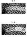
- a portion around a starting point of the broken surface was observed by a stereoscopic microscope to identify the cold flakes, and the area ratio of the cold flakes was then calculated.
- the calculation result is shown in Table 1.
- a value of stress that is to act on the starting point of the broken surface was calculated in advance by stress analysis, and then, a stress range up to 1/2 of the stress value was set as a broken surface observation range.
- the observation range of the area ratio of the cold flakes was set as a range up to a position of 15 mm from the starting point.
- FIG. 4A shows a broken surface of "Example 1" in Table 1
- FIG. 4B shows a broken surface of "Comparative example 1" in Table 1
- Portions surrounded by dashed lines in FIG. 4B represent portions for which the area (ratio) of the cold flakes is observed (calculated).
- the area ratio of the cold flakes is schematically calculated an actual casting site, for example, by manufacturing boundary samples in advance, it is possible to simplify the step.
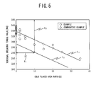
- the relationship between the Torsional breakage torque value obtained in the strength reduction ratio calculation step and the area ratio of the cold flakes may be plotted as in a graph shown in FIG.. 5 .
- Examples 1 to 16 are indicated by “ ⁇ ”
- Comparative examples 1 to 6 are indicated by " ⁇ "
- a straight line L1 that represents the "(strength reduction ratio" is defined from the respective Examples and Comparative examples that are plotted.
- the straight line L1 is calculated by a regression line obtained from the respective Examples and Comparative examples by a least squares method. In this manner, the strength reduction ratio of the die cast product that is a target is calculated and is represented by the straight line L1.
- a lower management limit line L2 which is defined by -3 ⁇ ( ⁇ is the standard deviation) using each point on the straight line L1 that represents the "strength reduction ratio" as an average value, is defined as a "threshold value”.
- the strength evaluation area ratio (a range of the area ratio of the cold flakes that is preferable as the examples (indicated by R1 in FIG. 5 )) is calculated from the lower management limit line L2 and a “desired strength range (indicated by R2 in FIG. 5 )".
- the die casting product that is a target in a case where the torsional breakage torque value is set to "260 Nm or greater" as the “desired strength range" of the die casting product that is a target, as the die casting product that is preferable as the examples, a die casting product in which the area ratio of the cold flakes (strength evaluation area ratio) is 10% or less is emphasizedly evaluated based on the lower management limit line L2.
- the present embodiment by observing the broken surface of the die casting product for which the breakage test is performed and by estimating the strength reduction ratio based on the area ratio of the cold flakes in the obtained broken surface, it is possible to provide a strength evaluation method that is simple and reliable. Thus, it is possible to prevent the problem that a special inspection apparatus is necessary and operation time is long in the strength evaluation method based on the cold flakes detection in the related art in which the broken surface is abraded and is observed by the optical microscope or in which the ultrasonic flaw detection is used.
- the strength evaluation is performed with only the torsional breakage torque value, deformation of the jig, a setting error of the product or variation of a manual torque application speed may occur, which may result in insufficient reliability.
- the present embodiment it is possible to perform the strength evaluation with high accuracy.
- the invention is not limited thereto, and various modifications and improvements may be made.
- the invention is not be applied to only the simple strength evaluation, but may also be applied to setting of appropriate die casting conditions. Specifically, as in the present examples, by setting the melt temperature to 670°C or higher, and preferably, to 680°C or higher, it is possible to set the ratio of the cold flakes to 10% or less, to thereby secure sufficient strength.
- FIGs 6A to 6C are diagrams illustrating a six axis ultrasonic flaw detector used in the strength evaluation method of the die casting product according to the present embodiment.
- FIG. 6A is a diagram illustrating the entire detector
- FIG. 6B is a diagram illustrating details of a detection target and a turntable
- FIG. 6C is a diagram illustrating an internal defect detection.
- reference numeral 11 represents an aluminum die casting product that is a strength evaluation target in the present embodiment, which is a column housing of an electric power steering device, for example.
- the aluminum die casting product (column housing) 11 is loaded onto a turntable 12, and then, a probe 13 moves down from the upside while the turntable 12 is rotating to detect the inside of the aluminum die casting product (column housing) 11 in a spiral form Since the die casting product (column housing) 11 of the present embodiment includes a cylindrical portion, a high stress portion of the cylindrical portion (to be described later) is detected by the ultrasonic flaw detector to detect an internal defect.
- an evaluation gate was set between a front surface echo and a rear surface echo of the aluminum die casting product (column housing) 11.
- the evaluation gate refers to a flaw detection range in an ultrasonic wave irradiation direction or in a reflection direction.
- ultrasonic waves oscillating from the probe 13 are reflected from the front surface or the rear surface of the aluminum die casting product (column housing) 11 to be returned.
- the reflected waves correspond to the front surface echo and the rear surface echo, respectively.
- the inner circumferential surface of the cylindrical portion of the aluminum die casting product (column housing) 11 is turning-processed.
- the ultrasonic waves are hardly reflection diffused from the inner circumferential surface, thereby making it easy to detect the defect echo..
- a key Prior to the detection, a key was inserted into a key lock portion of the column housing that is the die casting product 11 according to the present embodiment, and then, stress analysis was performed under the same load condition as in a torsion test in which a load was applied in a torsional direction..
- a portion indicated by "A" in FIG. 8 that is, the key lock portion is a portion where the stress is highest.
- the breakage occurs in the key lock portion of the column housing. In other words, in the high stress portion (key lock portion), the breakage using the internal defect as the starting point easily occurs, and thus, the internal defect of the high stress portion was determined to be detected.
- FIG. 9 illustrates a detection range of a high stress portion (key lock portion) 15 of the die casting product (column housing) 11 according to the present embodiment.
- a range of 12 mm in the axial direction of the cylindrical portion of the column housing, including the above-described portion where the stress is highest, is a target of the internal defect detection.
- This internal defect detection range refers to a stress range of 50% or greater of the maximum stress
- An ultrasonic flaw detection is performed for the inside of the aluminum die casting product (column housing) 11 in the internal defect detection range including the high stress portion (key lock portion) 15.
- FIG. 10 the internal defect is shown in a diagram in which the aluminum die casting product (column housing) 11 is cut from a slit portion and the inside thereof is developed.
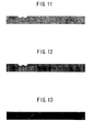
- FIG.. 11 illustrates a defect detection image obtained by the ultrasonic flaw detection in the above-described defect detection range of the aluminum die casting product (column housing) 11.
- the defect detection range is 12 mm in the height direction and is the entire inner circumference
- the length of a transverse axis of the image is 119 mm (the length of an inner circumference having an inner diameter of ⁇ 38 mm)
- the length of a longitudinal axis of the image is 12 mm.
- An echo strength of 50% is used as a threshold value
- an image obtained by binarizing echoes equal to or greater than the threshold value and echoes equal to or less than the threshold value for color division with respect to the defect detection image is shown in FIG. 12 .
- the echo strength of 50% refers to an echo strength in which a master test piece having a defect area of 0.2 mm 2 is adjusted to maintain the same area even in the image analysis to be described later. Further, a result obtained by performing the image analysis for the respective internal defects having the echo strength of 50% shown in FIG. 12 is shown in FIG.. 13 ..
- Table 2 represents the areas of all the internal defects analyzed in this manner.
- the total area of the internal defects is 4.99 mm 2
- the total defect detection area is 1400 mm 2 .
- a value by dividing the total area of the internal defects by the total defect detection area was defined as a defect ratio, and an internal defect state and the strength of the aluminum die casting product were evaluated by the defect ratio.
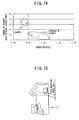
- FIG. 14 is a graph illustrating the results in Table 3.
- Defect ratio (%) Number of torsion Example 0.29% 35 0.43% 33 0.46% 32 Comparative example 0.53% 12 0.61% 10 0.83% 7 1.16% 4
- the defect ratio exceeds 0.5%, the number of torsion when the breakage occurs in the torsion test is noticeably reduced.
- verification was performed by changing an ultrasonic flaw detection range, particularly, a range in the axial direction of the cylindrical portion of the column housing.
- the ultrasonic flaw detection of the internal defect was performed in a stress range of 80% or greater of the maximum stress calculated by the above-described stress analysis.
- the internal defect detection range in the axial direction of the cylindrical portion of the column housing was set to 4 mm as shown in FIG. 15 ..
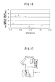
- Table 4 represents the relationship between the defect ratio of the internal defect inside the high stress portion (key lock portion) 15 and the number of torsion when the breakage occurs in the torsion test. Further, FIG. 16 is a graph illustrating the results in Table 4.
- Defect ratio (%) Number of torsion Comparative example 0.42% 35 0.30% 33 0.39% 32 0.13% 12 0.71% 10 1.58% 7 0.95% 4
- the ultrasonic flaw detection of the internal defect is performed in the stress range of 80% or greater of the maximum stress
- the relationship between the defect ratio and the number of torsion when the breakage occurs shows variation.
- the ultrasonic flaw detection of the internal defect was performed in a stress range of 5% or greater of the maximum stress calculated by the above-described stress analysis.
- An internal defect detection range in the axial direction of the cylindrical portion of the column housing was 60 mm, as shown in FIG. 17 .
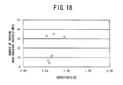
- Table 5 represents the relationship between the defect ratio of the internal defect inside the high stress portion (key lock portion) 15 and the number of torsion when the breakage occurs in the torsion test Further, FIG. 18 is a graph illustrating the results in Table 5.
- Table 5 Defect ratio (%) Number of torsion Comparative example 0.71% 35 0.54% 33 0.95% 32 0.66% 12 0.64% 10 0.57% 7 0.60% 4
- the defect ratio is approximately uniform, regardless of the number of torsion when the breakage occurs. It is considered that this is due to a wide defect detection range and detection of a large amount of data outside the broken portion.
- the defect ratio is 0.54% and the number of torsion is 33 and a case where the defect ratio is 0.60% and the number of torsion is 4
- the defect ratio was 0.60% and the number of torsion is 4
- the ultrasonic flaw detection is performed, with respect to the high stress portion of the column housing (die casting product) 11 calculated by the stress analysis in advance, for the internal defect in a predetermined range of the high stress portion, and the column housing (die casting product) 11 is evaluated to have a predetermined strength when the defect ratio obtained by dividing the total area of the internal defects in the predetermined range by the total defect detection area is less than or equal to a predetermined value.
- the strength of an actual column housing (die casting product) 11 is possible to appropriately evaluate the strength of an actual column housing (die casting product) 11.
- the predetermined range of the high stress portion to the stress range of 50% or greater of the maximum stress of the high stress portion, it is possible to more appropriately evaluate the strength of the column housing (die casting product) 11.
- the die casting product of the invention by performing the strength evaluation by the above-described strength evaluation method and by setting the defect ratio obtained by dividing the total area of the internal defects in the predetermined range of the high stress portion by the total defect detection area to 0.5% or less, it is possible to obtain the column housing (die casting product) 11 having a predetermined strength.
Landscapes
- Engineering & Computer Science (AREA)
- Mechanical Engineering (AREA)
- Physics & Mathematics (AREA)
- Biochemistry (AREA)
- Health & Medical Sciences (AREA)
- Life Sciences & Earth Sciences (AREA)
- Chemical & Material Sciences (AREA)
- Analytical Chemistry (AREA)
- General Health & Medical Sciences (AREA)
- General Physics & Mathematics (AREA)
- Immunology (AREA)
- Pathology (AREA)
- Acoustics & Sound (AREA)
- Investigating Or Analyzing Materials By The Use Of Ultrasonic Waves (AREA)
- Investigating Strength Of Materials By Application Of Mechanical Stress (AREA)
- Investigating And Analyzing Materials By Characteristic Methods (AREA)
Abstract
Alternatively, ultrasonic flaw detection is performed for an internal defect in a predetermined range of a high stress portion of the die casting product, calculated by stress analysis in advance, and the die casting product is evaluated to have a predetermined strength when a defect ratio obtained by dividing a total area of the internal defect in the predetermined range by a total defect detection area is less than or equal to a predetermined value.
Description
- The present invention relates to a strength evaluation method of a die casting product, and a die casting product used in an electric power steering device of a vehicle (for example, a column housing made of an aluminum die casting).
- In the related art, in order to prevent burglary of an automobile, a steering lock device that stops an engine when an ignition switch key is pulled out and also prevents rotation of a steering wheel has been widely used.
- A steering column that serves as a main body and an attachment part of the steering lock device used in this manner is required to be solid and not to be easily broaken. For example, JIS D5812 or the like regulates that no functional abnormality occur even when a torque of 200 Nm is applied to a steering shaft in a state where the steering shaft is locked.
- Here, in order to reduce the weight of the steering column, in many cases, the steering column is made of a die casting of a light metal such as aluminum or magnesium, for example. Accordingly, an internal defect occurs in the steering column, and thus, if excessive torque is applied, there is a fear that the steering column may be broken. Thus, it is important how to evaluate the strength.
- In particular, a strength decrease due to cold flakes is known as an internal defect of a die casting. Thus, for the strength evaluation, it is necessary to inspect the cold flakes.
- As an inspection method of such cold flakes, PTLs 1 to 3 disclose the following techniques.
- First, PTL 1 discloses a technique in which a mixture of a component (Pb) that is easily detected by cold flakes detection apparatus that employs radiation, magnetism, ultrasonic waves or the like and a sleeve lubricant is coated on the inner surface of a sleeve and the detection sensitivity of cold flakes increases as Pb enters the cold flakes and a cavity.
- Further,
PTL 2 discloses a technique that obtains dispersion information on cold flakes in a non-destructive state using a measurement method in which ultrasonic flaw detection and X-ray CT scanning are combined. - Specifically, ultrasonic waves are irradiated onto an aluminum die casting product, and a blow hole and cold flakes of the aluminum die casting product are detected based on information on sound waves from the aluminum die casting product to obtain first internal defect three-dimensional distribution data. Further, the aluminum die casting product is measured by the X-ray CT scanning, and the blow hole of the aluminum die casting product is detected from plural cross-sectional images of the aluminum die casting product to obtain second internal defect three-dimensional distribution data. Then, the first internal defect three-dimensional distribution data and the second internal defect three-dimensional distribution data are compared with each other to obtain three-dimensional distribution data on the cold flakes of the aluminum die casting product.
- Further,
PTL 3 discloses a simple cold flakes inspection method in which a test piece cut out of a runner portion is abraded and corroded and an area ratio of cold flakes is then calculated based on observation of the cold flakes. - Further, as another strength evaluation method of an aluminum die casting product, PTL 4 discloses a technique in which ultrasonic flaw detection is performed for an aluminum die casting product having a complex member therein and a distance from a front surface to the complex member, an impregnation state of aluminum melt with respect to the complex member, a breakage state and the like are measured to determine whether the aluminum die casting product is good or bad.
-
- PTL 1:
JP 3-226668 A - PTL 2:
JP 2005-91288 A - PTL 3:
JP 2007-111728 A - PTL 4:
JP 2004-144489 A - However, in the techniques disclosed PTL 1 to 3, since a special inspection apparatus is necessary, operation time becomes long. Further, it is difficult to perform the strength evaluation in a casting site. Furthermore, since the accuracy of measurement and detection is not sufficient, it is difficult to perform the strength evaluation with high accuracy.
- Specifically, the technique disclosed in PTL 1 has an advantage in that a non-destructive inspection is available, but since it is necessary to perform an inspection using a special apparatus that employs radiation, magnetism, ultrasonic waves or the like after casting, operation time becomes long. Further, it is difficult to perform the strength evaluation in a casting site. Furthermore, since the accuracy of measurement and detection is not sufficient, it is difficult to perform the strength evaluation with high accuracy. "
- Further, similar to the technique disclosed in PTL 1, the technique disclosed in
PTL 2 has an advantage in that a non-destructive inspection is available, but since it is necessary to perform an inspection using a special apparatus for ultrasonic flaw detection or CT scanning after casting, operation time becomes long. Further, it is difficult to perform the strength evaluation in a casting site. Furthermore, since the accuracy of measurement and detection is not sufficient, it is difficult to perform the strength evaluation with high accuracy. - Furthermore, the technique disclosed in
PTL 3 has an advantage in that a special inspection apparatus is not necessary, but since the abrasion and corrosion are necessary, operation time becomes long. Further, since the test piece is cut out of the runner portion instead of a product, it is difficult to perform the strength evaluation with high accuracy. - In addition, the strength evaluation method of the aluminum die casting product disclosed in PTL 4 can perform only the measurement of the impregnation state or the breakage with respect to the aluminum die casting product having the complex member therein, but cannot evaluate the strength of an aluminum die casting product having no complex member.
- On the other hand, the strength evaluation method of the aluminum die casting product disclosed in
PTL 2 can perform the evaluation of an aluminum die casting product having no complex member. However, it is substantially difficult to perform the inspection for all parts of a large-sized aluminum die casting product or a complicated aluminum die casting product, for example. In an actual aluminum die casting product, it is difficult to avoid an internal defect such as a blow hole, and breakage may occur from the internal defect as a starting point. Further, in many cases, the aluminum die casting product has a complicated shape, and thus, it is difficult to detect the internal defect by ultrasonic flaw detection, for example. Furthermore, it is not obvious which portion the strength is to be evaluated in - In order to solve the above-mentioned problems, an obj ect of the invention is to provide a strength evaluation method of a die casting product capable of shortening operation time, performing a strength evaluation (strength guarantee) at a casting site and performing the strength evaluation with high accuracy, and such a die casting product.
- Further, another object of the invention is to provide a strength evaluation method of a die casting product capable of appropriately evaluating the strength of an actual die casting product and obtaining a die casting product having a predetermined strength, and such a die casting product.
- In order to achieve the above-mentioned objects, according to an embodiment of the invention, there is provided a strength evaluation method of a die casting product, comprising: a casting step of casting a die casting product; a breakage step of performing a breakage test of the die casting product after casting; a strength reduction ratio calculation step of measuring an area ratio of cold flakes present in a broken surface of the die casting product in the breakage step, and obtaining a strength reduction ratio from the relationship between a torsional breakage torque value in the breakage step and the area ratio; and a strength evaluation area ratio calculation step of calculating a threshold value of -3σ (σ is a standard deviation) using the strength reduction ratio as an average value, and calculating a strength evaluation area ratio of the die casting product from the threshold value and a predetermined strength range.
- Further, in the strength evaluation method of the die casting product described above, it is preferable that the casting step be a casting step based on JIS D5812, the die casting product be an aluminum column housing, and the breakage test be a torsion test for the die casting product.
- Further, in the strength evaluation method of the die casting product described above, it is preferable that the die casting product be used in a steering lock provided with an ignition switch for vehicle steering.
- Further, according to another embodiment of the invention, there is provided a column housing made of an aluminum die casting in which the strength is evaluated by the strength evaluation method of the die casting product described above, in which the column housing made of an aluminum die casting is formed with a hole for the steering lock, and an area ratio of cold flakes in the area of a broken surface ranged up to a stress of 1/2 of a maximum value of stress acting on a breakage starting point, calculated by stress analysis from the breakage starting point when the hole for the steering lock is broken by the torsion test, is less than 10%.
- Further, according to still another embodiment of the invention, there is provided a strength evaluation method of a die casting product, comprising: performing, with respect to a high stress portion obtained by performing stress analysis for the die casting product in advance, ultrasonic flaw detection for an internal defect in a predetermined range of the high stress portion; and evaluating that the die casting product has a predetermined strength when a defect ratio obtained by dividing a total area of the internal defect in the predetermined range by a total defect detection area is less than or equal to a predetermined value..
- Here, it is preferable that the predetermined range of the high stress portion be a stress range of 50% or greater of a maximum stress of the high stress portion..
- Further, according to still another aspect of the invention, there is provided a die casting product in which the strength is evaluated by the strength evaluation method of the die casting product described above, in which the defect ratio is 0.5% or less.
- Further, it is preferable that the die casting product be a column housing used in an electric power steering device of a vehicle, and the high stress portion is a key lock portion of the column housing
- According to the embodiment of the invention, it is possible to provide a strength evaluation method of a die casting product capable of shortening operation time, performing a strength evaluation at a casting site whenever necessary and performing the strength evaluation with high accuracy, and such a die casting product. Further, according to the strength evaluation method of a die casting product according to the embodiment of the invention, since ultrasonic flaw detection is performed for an internal defect in a predetermined range of the high stress portion with respect to a high stress portion obtained by performing stress analysis for the die casting product in advance; and the die casting product is evaluated to have a predetermined strength when a defect ratio obtained by dividing a total area of the internal defect in the predetermined range by a total defect detection area is less than or equal to a predetermined value, it is possible to appropriately evaluate the strength of an actual die casting product
- Furthermore, since the predetermined range of the high stress portion is a stress range of 50% or greater of a maximum stress of the high stress portion, it is possible to more appropriately evaluate the strength of the die casting product.
- In addition, according to the die casting product according to the embodiment of the invention, by evaluating the strength by the strength evaluation method of the die casting product according to the embodiment of the invention, and by setting a defect ratio obtained by dividing a total area of the internal defect in the predetermined range of the high stress portion by a total defect detection area to be 0.5% or less, it is possible to obtain a die casting product having a predetermined strength.
-
-
FIG. 1 is a flowchart illustrating a step in a first embodiment of a strength evaluation method of a die casting product; -
FIG. 2 is a perspective view illustrating a configuration of a steering column housing in the first embodiment of the strength evaluation method of the die casting product; -
FIG. 3 is a schematic diagram illustrating a configuration of a torsion tester in the first embodiment of the strength evaluation method of the die casting product; -
FIGs 4A and 4B are stereoscopic microphotographs illustrating an observation example of an area ratio of cold flakes of a broken surface in the first embodiment of the strength evaluation method of the die casting product; -
FIG. 5 is a graph illustrating the relationship between an area ratio of cold flakes and a torsional breakage torque (desired strength range) in the first embodiment of the strength evaluation method of the die casting product; -
FIGs 6A to 7C are diagrams illustrating a second embodiment of a strength evaluation method of a die casting product; -
FIGs 7A and 7B are diagrams illustrating internal defect detection in the strength evaluation method of the die casting product inFIGs 6A to 6C ; -
FIG. 8 is a diagram illustrating a high stress portion of a die casting product; -
FIG. 9 is a diagram illustrating an internal defect detection range of a high stress portion of a die casting product; -
FIG. 10 is a diagram illustrating an image obtained in the internal defect detection inFIGs 6A to 6C ; -
FIG. 11 is a diagram illustrating a defect detection image obtained in the internal defect detection inFIGs 6A to 6C ; -
FIG. 12 is a diagram illustrating an image obtained by binarizing the defect detection image inFIG. 11 ; -
FIG. 13 is a diagram illustrating obtained by extracting an internal defect area from a binarized defect detection image inFIG. 12 by image analysis; -
FIG.. 14 is a diagram illustrating the relationship between a defect ratio of an internal defect in the detection range inFIG. 9 and the number of torsion when breakage occurs in a torsion test; -
FIG. 15 is a diagram illustrating an internal defect detection range of a high stress portion of a die casting product; -
FIG 16 is a diagram illustrating the relationship between a defect ratio of an internal defect in the detection range inFIG. 15 and the number of torsion when breakage occurs in a torsion test; -
FIG. 17 is a diagram illustrating an internal defect detection range of a high stress portion of a die casting product; and -
FIG. 18 is a diagram illustrating the relationship between a defect ratio of an internal defect in the detection range inFIG. 17 and the number of torsion when breakage occurs in a torsion test. - Hereinafter, a first embodiment of a strength evaluation method of a die casting product will be described with reference to the drawings.
- As shown in
FIG. 1 , the strength evaluation method of the present embodiment includes a casting step (S1), a breakage step (S2), a strength reduction ratio calculation step (S3), and a strength evaluation area ratio calculation step (S4). - The casting step in the present embodiment refers to a step of performing die casting using ADC12 that is an Al-Si-Cu based aluminum alloy of JIS H5302, for example. It is preferable that a die casting product obtained in this step be a
steering column housing 3 of an automobile steering device shown inFIG. 2 . - The breakage step in the present embodiment refers to a step of performing a breakage test in a casting site for the die casting product obtained in the above-described casting step. It is preferable that the breakage test be a torsion test.
- In this torsion test, specifically, as shown in
FIG 3 , a key lock jig 1 screw-coupled with the steering column housing (die casting product) 3 includes a convex key that protrudes from a key hole portion of thesteering column housing 3 toward the inner diameter of thesteering column housing 3. Further, a concave portion that is engaged with the key is formed in atorque transmission shaft 2. Torque transmits from thetorque transmission shaft 2 to the key seat portion 4 of thesteering column housing 3 through the convex key of the key lock jig 1, and causes the steering column housing to be broken using a corner portion of the key seat portion 4 as a starting point. - The strength reduction ratio calculation step refers to a step of measuring an area ratio of cold flakes in a broken surface of the die casting product in the breakage step and calculating a strength reduction ratio from the relationship between a torsional breakage torque value and the area ratio in the breakage step
- The strength evaluation area ratio calculation step refers to a step of calculating a strength evaluation area ratio of the die casting product based on the strength reduction ratio calculated in the strength reduction ratio calculation step. Specifically, in this step, first, a threshold value of -3σ (σ is a standard deviation) is calculated using the strength reduction ratio calculated in the strength reduction ratio calculation step as an average value. Then, the strength evaluation area ratio of the die casting product is calculated from the threshold value and a predetermined strength range.
- Hereinafter, examples of the strength evaluation method of the die casting product according to the first embodiment and the die casting product (column housing made of aluminum die casting) in which the strength is evaluated by the strength evaluation method will be described. Table 1 illustrates the relationship between conditions of the casting step in the present examples, the strength of the die casting product and the area ratio of the cold flakes.
- Die casting was performed under the conditions shown in Table 1, using
ADC 12 that is the Al-Si-Cu based aluminum alloy of JIS H5302, to obtain steering column housings of Examples 1 to 16 and Comparative examples 1 to 6. - Then, each steering column housing 1 of Examples 1 to 16 and Comparative examples 1 to 6 was caused to be torsionally broken using a torsion tester shown in
FIG. 3 , and then, a torsional torque value when the breakage is occurred was measured. The measurement result is shown Table 1[Table 1] Melt temperature (°C) Biscuit thickness (mm) Torsional breakage torque value (Nm) Cold flakes area ratio (%) Example 1 680 30 355 0 Example 2 680 30 333 0 Example 3 680 30 312 2 Example 4 680 30 341 0 Example 5 680 30 350 0 Example 6 680 30 345 2 Example 7 680 30 340 2 Example 8 680 30 345 0 Example 9 680 30 331 0 Example 10 680 30 356 0 Example 11 670 20 290 10 Example 12 670 20 330 0 Example 13 670 20 321 5 Example 14 670 20 313 5 Example 15 670 20 345 0 Example 16 670 20 327 2 Comparative example 1 660 15 278 20 Comparative example 2 660 15 274 15 Comparative example 3 660 15 240 35 Comparative example 4 660 15 292 15 Comparative example 5 660 15 263 25 Comparative example 6 660 15 289 20 - Then, a portion around a starting point of the broken surface was observed by a stereoscopic microscope to identify the cold flakes, and the area ratio of the cold flakes was then calculated. The calculation result is shown in Table 1. Here, a value of stress that is to act on the starting point of the broken surface was calculated in advance by stress analysis, and then, a stress range up to 1/2 of the stress value was set as a broken surface observation range. In the present examples, the observation range of the area ratio of the cold flakes was set as a range up to a position of 15 mm from the starting point.
- Further, observation examples of a broken surface are shown in
FIGs 4A to 4C. FIG. 4A shows a broken surface of "Example 1" in Table 1, andFIG. 4B shows a broken surface of "Comparative example 1" in Table 1 Portions surrounded by dashed lines inFIG. 4B represent portions for which the area (ratio) of the cold flakes is observed (calculated). In a case where the area ratio of the cold flakes is schematically calculated an actual casting site, for example, by manufacturing boundary samples in advance, it is possible to simplify the step. - Here, the relationship between the Torsional breakage torque value obtained in the strength reduction ratio calculation step and the area ratio of the cold flakes may be plotted as in a graph shown in
FIG.. 5 . InFIG. 5 , Examples 1 to 16 are indicated by "○", and Comparative examples 1 to 6 are indicated by "◆" - Further, as shown in
FIG. 5 , a straight line L1 that represents the "(strength reduction ratio" is defined from the respective Examples and Comparative examples that are plotted. The straight line L1 is calculated by a regression line obtained from the respective Examples and Comparative examples by a least squares method. In this manner, the strength reduction ratio of the die cast product that is a target is calculated and is represented by the straight line L1. - Thereafter, as shown in
FIG.. 5 , a lower management limit line L2, which is defined by -3σ (σ is the standard deviation) using each point on the straight line L1 that represents the "strength reduction ratio" as an average value, is defined as a "threshold value". Further, the strength evaluation area ratio (a range of the area ratio of the cold flakes that is preferable as the examples (indicated by R1 inFIG. 5 )) is calculated from the lower management limit line L2 and a "desired strength range (indicated by R2 inFIG. 5 )". For example, in a case where the torsional breakage torque value is set to "260 Nm or greater" as the "desired strength range" of the die casting product that is a target, as the die casting product that is preferable as the examples, a die casting product in which the area ratio of the cold flakes (strength evaluation area ratio) is 10% or less is emphasizedly evaluated based on the lower management limit line L2. - As described above, according to the present embodiment, by observing the broken surface of the die casting product for which the breakage test is performed and by estimating the strength reduction ratio based on the area ratio of the cold flakes in the obtained broken surface, it is possible to provide a strength evaluation method that is simple and reliable. Thus, it is possible to prevent the problem that a special inspection apparatus is necessary and operation time is long in the strength evaluation method based on the cold flakes detection in the related art in which the broken surface is abraded and is observed by the optical microscope or in which the ultrasonic flaw detection is used. Further, in the related art, since the strength evaluation is performed with only the torsional breakage torque value, deformation of the jig, a setting error of the product or variation of a manual torque application speed may occur, which may result in insufficient reliability. On the other hand, according to the present embodiment, it is possible to perform the strength evaluation with high accuracy.
- Hereinabove, the first embodiment of the strength evaluation method of the die casting product is described, but the invention is not limited thereto, and various modifications and improvements may be made. For example, as described above, the invention is not be applied to only the simple strength evaluation, but may also be applied to setting of appropriate die casting conditions. Specifically, as in the present examples, by setting the melt temperature to 670°C or higher, and preferably, to 680°C or higher, it is possible to set the ratio of the cold flakes to 10% or less, to thereby secure sufficient strength.
- Next, a second embodiment of a strength evaluation method of a die casting product will be described with reference to drawings.
-
FIGs 6A to 6C are diagrams illustrating a six axis ultrasonic flaw detector used in the strength evaluation method of the die casting product according to the present embodiment.FIG. 6A is a diagram illustrating the entire detector,FIG. 6B is a diagram illustrating details of a detection target and a turntable, andFIG. 6C is a diagram illustrating an internal defect detection. InFIGs 6A to 6C ,reference numeral 11 represents an aluminum die casting product that is a strength evaluation target in the present embodiment, which is a column housing of an electric power steering device, for example. - In the present embodiment, the aluminum die casting product (column housing) 11 is loaded onto a
turntable 12, and then, aprobe 13 moves down from the upside while theturntable 12 is rotating to detect the inside of the aluminum die casting product (column housing) 11 in a spiral form Since the die casting product (column housing) 11 of the present embodiment includes a cylindrical portion, a high stress portion of the cylindrical portion (to be described later) is detected by the ultrasonic flaw detector to detect an internal defect. - In the detection, as shown in
FIG 7A , an evaluation gate was set between a front surface echo and a rear surface echo of the aluminum die casting product (column housing) 11. The evaluation gate refers to a flaw detection range in an ultrasonic wave irradiation direction or in a reflection direction. In the ultrasonic flaw detection, ultrasonic waves oscillating from theprobe 13 are reflected from the front surface or the rear surface of the aluminum die casting product (column housing) 11 to be returned. The reflected waves correspond to the front surface echo and the rear surface echo, respectively. As shown inFIG. 7B , in a case where aninternal defect 14 is present within the detection range of the aluminum die casting product (column housing) 11, a defect echo appears between the front surface echo and the rear surface echo, that is, in the range of the evaluation gate. Since a time point of the front surface echo and a time point of the rear surface echo may be known in advance, an echo present between these time points becomes the defect echo. Further, a technique of showing the greatest defect echo inside the aluminum die casting product (column housing) 11 was used. Here, the inner diameter of the cylindrical portion of the column housing that is thedie casting product 11 according to the present embodiment was set to ϕ 38 mm, and as described later, the detection range was set to 12 mm in the axial direction of the cylindrical portion. Further, the inner circumferential surface of the cylindrical portion of the aluminum die casting product (column housing) 11 is turning-processed. Thus, the ultrasonic waves are hardly reflection diffused from the inner circumferential surface, thereby making it easy to detect the defect echo.. - Prior to the detection, a key was inserted into a key lock portion of the column housing that is the
die casting product 11 according to the present embodiment, and then, stress analysis was performed under the same load condition as in a torsion test in which a load was applied in a torsional direction.. As a result, it can be understood that a portion indicated by "A" inFIG. 8 , that is, the key lock portion is a portion where the stress is highest. Further, in the torsion test in the related art, similarly, the breakage occurs in the key lock portion of the column housing. In other words, in the high stress portion (key lock portion), the breakage using the internal defect as the starting point easily occurs, and thus, the internal defect of the high stress portion was determined to be detected. -
FIG. 9 illustrates a detection range of a high stress portion (key lock portion) 15 of the die casting product (column housing) 11 according to the present embodiment. In the present embodiment, a range of 12 mm in the axial direction of the cylindrical portion of the column housing, including the above-described portion where the stress is highest, is a target of the internal defect detection. This internal defect detection range refers to a stress range of 50% or greater of the maximum stress An ultrasonic flaw detection is performed for the inside of the aluminum die casting product (column housing) 11 in the internal defect detection range including the high stress portion (key lock portion) 15. Further, as described inFIG. 10 , the internal defect is shown in a diagram in which the aluminum die casting product (column housing) 11 is cut from a slit portion and the inside thereof is developed. -
FIG.. 11 illustrates a defect detection image obtained by the ultrasonic flaw detection in the above-described defect detection range of the aluminum die casting product (column housing) 11. As described above, since the defect detection range is 12 mm in the height direction and is the entire inner circumference, the length of a transverse axis of the image is 119 mm (the length of an inner circumference having an inner diameter of ϕ 38 mm), and the length of a longitudinal axis of the image is 12 mm. An echo strength of 50% is used as a threshold value, an image obtained by binarizing echoes equal to or greater than the threshold value and echoes equal to or less than the threshold value for color division with respect to the defect detection image is shown inFIG. 12 . Thin gray portions inFIG. 12 represent the internal defects having the echo strength of 50% or greater. The echo strength of 50% refers to an echo strength in which a master test piece having a defect area of 0.2 mm2 is adjusted to maintain the same area even in the image analysis to be described later. Further, a result obtained by performing the image analysis for the respective internal defects having the echo strength of 50% shown inFIG. 12 is shown inFIG.. 13 .. Here, a case where the number of pixels is 20 or less (the area is 0.2 mm2 or less) was determined to have no problem in the strength, and was excluded from an internal defect evaluation target. - Table 2 represents the areas of all the internal defects analyzed in this manner. The total area of the internal defects is 4.99 mm2, and the total defect detection area is 1400 mm2. In the present embodiment, a value by dividing the total area of the internal defects by the total defect detection area was defined as a defect ratio, and an internal defect state and the strength of the aluminum die casting product were evaluated by the defect ratio. In this example, the defect ratio is 4.99/1400 x 100=0.36
[Table 2] Defect area [mm2] 0.36 0.24 0.23 0.21 0.21 0.26 0.21 0.25 0.67 0.28 0.37 0.23 0.79 0.50 0.19 Total 4.99 - In a similar manner, with respect to seven aluminum die casting products (column housings) 11, an internal defect of a high stress portion (key lock portion) was detected by the ultrasonic flaw detection, the area of the detected internal defect was calculated by the image analysis, and the defect ratio was calculated by dividing the total area of the internal defects by the total defect detection area. Further, a torsion test was performed for the aluminum die casting products (column housings) 11 to detect the number of torsion until the breakage occurs. This torsion test is appended to Technical Standards for locking apparatus of four-wheeled vehicles, Attachment 7, Details Public Notice Attachment 1-7, Road Transport Vehicle Maintenance Standard 11-2 in Road Transport Vehicle Law. The test was performed based on a test procedure of a lock that acts on a steering device provided with a torque limit device regulated in
Attachment 2. Here, in the present embodiment, in consideration of a safety factor, a torque value was set to 200 Nm that is two times a standard value of 100 Nm. Then, the cycle was repeated to calculate the number of torsion until the breakage occurs. Table 3 represents the relationship between the defect ratio of an internal defect inside the high stress portion (key lock portion) 15 and the number of torsion when the breakage occurs in the torsion test Further,FIG.. 14 is a graph illustrating the results in Table 3.[Table 3] Defect ratio (%) Number of torsion Example 0.29% 35 0.43% 33 0.46% 32 Comparative example 0.53% 12 0.61% 10 0.83% 7 1.16% 4 - As is obvious from
FIG. 14 , it can be understood that if the defect ratio exceeds 0.5%, the number of torsion when the breakage occurs in the torsion test is noticeably reduced. In this regard, verification was performed by changing an ultrasonic flaw detection range, particularly, a range in the axial direction of the cylindrical portion of the column housing. First, the ultrasonic flaw detection of the internal defect was performed in a stress range of 80% or greater of the maximum stress calculated by the above-described stress analysis. The internal defect detection range in the axial direction of the cylindrical portion of the column housing was set to 4 mm as shown inFIG. 15 .. Further, the above-described torsion test was performed for the column housing in which the internal defect was detected to calculate the number of torsion until the breakage occurred. Table 4 represents the relationship between the defect ratio of the internal defect inside the high stress portion (key lock portion) 15 and the number of torsion when the breakage occurs in the torsion test. Further,FIG. 16 is a graph illustrating the results in Table 4.[Table 4] Defect ratio (%) Number of torsion Comparative example 0.42% 35 0.30% 33 0.39% 32 0.13% 12 0.71% 10 1.58% 7 0.95% 4 - As obvious from
FIG. 16 , in a case where the ultrasonic flaw detection of the internal defect is performed in the stress range of 80% or greater of the maximum stress, the relationship between the defect ratio and the number of torsion when the breakage occurs shows variation. As the cause of this, non-capturing of the internal defect that is a factor of the breakage starting point or a sufficient amount of data is considered. Then, the ultrasonic flaw detection of the internal defect was performed in a stress range of 5% or greater of the maximum stress calculated by the above-described stress analysis.. An internal defect detection range in the axial direction of the cylindrical portion of the column housing was 60 mm, as shown inFIG. 17 . Further, the above-described torsion test was performed for the column housing in which the internal defect was detected to calculate the number of torsion until the breakage occurs Table 5 represents the relationship between the defect ratio of the internal defect inside the high stress portion (key lock portion) 15 and the number of torsion when the breakage occurs in the torsion test Further,FIG. 18 is a graph illustrating the results in Table 5.[Table 5] Defect ratio (%) Number of torsion Comparative example 0.71% 35 0.54% 33 0.95% 32 0.66% 12 0.64% 10 0.57% 7 0.60% 4 - As is obvious from
FIG. 18 , in a case where the ultrasonic flaw detection of the internal defect is performed in the stress range of 5% or greater of the maximum stress, the defect ratio is approximately uniform, regardless of the number of torsion when the breakage occurs. It is considered that this is due to a wide defect detection range and detection of a large amount of data outside the broken portion. Actually, in comparison of both of cases where the numbers of torsions when the breakage occurs are different at the same level of the defect ratio (a case where the defect ratio is 0.54% and the number of torsion is 33 and a case where the defect ratio is 0.60% and the number of torsion is 4), in the latter case, the internal defect occurred around the starting point, whereas in the former case, the internal defects were dispersed. This example is considered as an example in which the defect ratio became uniform due to the wide defect detection range. - As described above, in the strength evaluation method of the die casting product according to the present embodiment, the ultrasonic flaw detection is performed, with respect to the high stress portion of the column housing (die casting product) 11 calculated by the stress analysis in advance, for the internal defect in a predetermined range of the high stress portion, and the column housing (die casting product) 11 is evaluated to have a predetermined strength when the defect ratio obtained by dividing the total area of the internal defects in the predetermined range by the total defect detection area is less than or equal to a predetermined value. Thus, it is possible to appropriately evaluate the strength of an actual column housing (die casting product) 11.
- Further, by setting the predetermined range of the high stress portion to the stress range of 50% or greater of the maximum stress of the high stress portion, it is possible to more appropriately evaluate the strength of the column housing (die casting product) 11.
- Furthermore, according to the die casting product of the invention, by performing the strength evaluation by the above-described strength evaluation method and by setting the defect ratio obtained by dividing the total area of the internal defects in the predetermined range of the high stress portion by the total defect detection area to 0.5% or less, it is possible to obtain the column housing (die casting product) 11 having a predetermined strength.
- Hereinabove, the second embodiment of the strength evaluation method of the die casting product is described, but the invention is not limited thereto, and various modifications and improvements may be made.
-
- 1
- key lock jig
- 2
- torque transmission shaft
- 3
- steering column housing
- 4
- key seat
- 11
- die casting product (column housing)
- 12
- turntable
- 13
- probe
- 14
- internal defect
- 15
- high stress portion (key lock portion)
Claims (8)
- A strength evaluation method of a die casting product, the method comprising:a casting step of casting a die casting product;a breakage step of performing a breakage test of the die casting product after casting;a strength reduction ratio calculation step of measuring an area ratio of cold flakes present in a broken surface of the die casting product in the breakage step, and calculating a strength reduction ratio from the relationship between a torsional breakage torque value in the breakage step and the area ratio; anda strength evaluation area ratio calculation step of obtaining a threshold value of -3σ (σ is a standard deviation) using the strength reduction ratio as an average value, and calculating a strength evaluation area ratio of the die casting product from the threshold value and a predetermined strength range.
- The strength evaluation method of a die casting product according to claim 1, wherein the casting step is a casting step based on JIS D5812, the die casting product is an aluminum column housing, and the breakage test is a torsion test for the die casting product.
- The strength evaluation method of a die casting product according to claim 1 or 2, wherein the die casting product is used in a steering lock provided with an ignition switch for automobile steering.
- A die casting product in which the strength is evaluated by the strength evaluation method of a die casting product according to claim 3,
wherein the die casting product is formed with a hole for the steering lock, and
wherein an area ratio of cold flakes in the area of a broken surface ranged up to a stress of 1/2 of a maximum value of stress acting on a breakage starting point, calculated by stress analysis from the breakage starting point when the hole for the steering lock is broken by the torsion test, is less than 10%. - A strength evaluation method of a die casting product, comprising:performing, with respect to a high stress portion obtained by performing stress analysis for the die casting product in advance, ultrasonic flaw detection for an internal defect in a predetermined range of the high stress portion; andevaluating whether the die casting product has a predetermined strength when a defect ratio obtained by dividing a total area of the internal defect in the predetermined range by a total defect detection area is less than or equal to a predetermined value.
- The strength evaluation method of a die casting product according to claim 5, wherein the predetermined range of the high stress portion is a stress range of 50% or greater of a maximum stress of the high stress portion.
- A die casting product in which the strength is evaluated by the strength evaluation method of a die casting product according to claim 5 or 6,
wherein the defect ratio is 0.5% or less. - The die casting product according to claim 7, wherein the die casting product is a column housing used in an electric power steering device of an automobile, and the high stress portion is a key lock portion of the column housing.
Applications Claiming Priority (3)
| Application Number | Priority Date | Filing Date | Title |
|---|---|---|---|
| JP2012043827 | 2012-02-29 | ||
| JP2012129858 | 2012-06-07 | ||
| PCT/JP2012/004686 WO2013128500A1 (en) | 2012-02-29 | 2012-07-24 | Die-cast product rigidity evaluation method and die-cast product |
Publications (2)
| Publication Number | Publication Date |
|---|---|
| EP2821772A1 true EP2821772A1 (en) | 2015-01-07 |
| EP2821772A4 EP2821772A4 (en) | 2015-10-21 |
Family
ID=49081766
Family Applications (1)
| Application Number | Title | Priority Date | Filing Date |
|---|---|---|---|
| EP12870021.8A Withdrawn EP2821772A4 (en) | 2012-02-29 | 2012-07-24 | Die-cast product rigidity evaluation method and die-cast product |
Country Status (5)
| Country | Link |
|---|---|
| US (1) | US20150044090A1 (en) |
| EP (1) | EP2821772A4 (en) |
| JP (1) | JPWO2013128500A1 (en) |
| CN (1) | CN103635787B (en) |
| WO (1) | WO2013128500A1 (en) |
Cited By (1)
| Publication number | Priority date | Publication date | Assignee | Title |
|---|---|---|---|---|
| CN106238343A (en) * | 2016-08-17 | 2016-12-21 | 浙江大学 | A kind of casting quality safety management system |
Families Citing this family (8)
| Publication number | Priority date | Publication date | Assignee | Title |
|---|---|---|---|---|
| US9383343B2 (en) * | 2011-02-28 | 2016-07-05 | Nsk Ltd. | Strength evaluating method for aluminum die cast part, aluminum die cast part, and defect detecting method for the same |
| JP5943402B1 (en) * | 2015-03-18 | 2016-07-05 | 学校法人早稲田大学 | Measuring apparatus, method, computer program and computer-readable recording medium for quantifying casting defects |
| CN106959248B (en) * | 2017-05-04 | 2023-06-02 | 广州建设工程质量安全检测中心有限公司 | A test method for detecting damage and cracks of concrete specimens |
| CN108627400B (en) * | 2018-04-17 | 2020-12-25 | 国网山西省电力公司电力科学研究院 | Device and method for testing stable bearing capacity of angle steel crossed inclined material |
| CN110005659B (en) * | 2019-04-08 | 2020-08-11 | 深圳市华星光电技术有限公司 | Real-time monitoring method for air cylinder |
| CN115047162B (en) * | 2022-06-24 | 2024-02-06 | 张家港沙龙精密管业有限公司 | Defect detection method and system for heat treatment of steel pipe |
| CN116539834A (en) * | 2023-05-18 | 2023-08-04 | 中信戴卡股份有限公司 | Method for rapidly evaluating quality of aluminum liquid |
| CN117272722B (en) * | 2023-08-28 | 2024-06-21 | 湖北汽车工业学院 | A standard and method for studying the mechanical properties of magnesium alloy steering wheels |
Family Cites Families (29)
| Publication number | Priority date | Publication date | Assignee | Title |
|---|---|---|---|---|
| JPS57187154A (en) * | 1981-05-15 | 1982-11-17 | Toyota Motor Corp | Method and device for inspecting quality of product produced by die casting machine |
| JPH03226668A (en) | 1990-01-31 | 1991-10-07 | Mazda Motor Corp | Inspection of cast product |
| CA2053132C (en) * | 1990-10-15 | 1997-05-06 | Hiromi Takagi | Method of discriminating quality of die-cast article and die-casting process using same |
| JPH0755723A (en) * | 1993-08-19 | 1995-03-03 | Sumitomo Metal Ind Ltd | Surface inspection method and apparatus used for its implementation |
| US5573606A (en) * | 1995-02-16 | 1996-11-12 | Gibbs Die Casting Aluminum Corporation | Aluminum alloy and method for making die cast products |
| JPH09325136A (en) * | 1996-06-04 | 1997-12-16 | Hitachi Ltd | Automatic defect evaluation method for centrifugal impeller |
| JPH1099961A (en) * | 1996-09-30 | 1998-04-21 | Alum Toreega Kaihatsu Kyodo Kumiai | High adhesion cast-in member and its manufacturing method |
| CN1330012A (en) * | 2000-06-20 | 2002-01-09 | 张�诚 | Antitheft lock of bicycle |
| JP4360509B2 (en) * | 2000-07-31 | 2009-11-11 | 独立行政法人物質・材料研究機構 | Evaluation method and manufacturing method of high fatigue strength in high strength steel |
| JP4202663B2 (en) * | 2001-03-28 | 2008-12-24 | 株式会社神戸製鋼所 | Steel material with excellent toughness |
| KR100439790B1 (en) * | 2001-08-09 | 2004-07-12 | 현대자동차주식회사 | Apparatus for testing durability of steering colume and keyset of vehicle |
| US20050000604A1 (en) * | 2001-09-04 | 2005-01-06 | Hiroshi Kawahara | Aluminum alloy, cast article of aluminum alloy, and method for producing cast article of aluminum alloy |
| DE10230276B4 (en) * | 2002-07-05 | 2005-05-19 | Daimlerchrysler Ag | AS die-cast alloy and method for producing an aggregate part from such an AS diecasting alloy |
| JP4061171B2 (en) | 2002-10-21 | 2008-03-12 | リョービ株式会社 | Method for determining the quality of a casting having a composite member inside |
| JP2005091288A (en) | 2003-09-19 | 2005-04-07 | Toyota Motor Corp | Method for identifying casting defects |
| WO2006134831A1 (en) * | 2005-06-17 | 2006-12-21 | Hitachi, Ltd. | Rotor for steam turbine and process for producing the same |
| JP2007111728A (en) * | 2005-10-19 | 2007-05-10 | Ryobi Ltd | Method for inspecting die-cast article |
| JP2007331530A (en) * | 2006-06-14 | 2007-12-27 | Tokai Rika Co Ltd | Steering lock device |
| JP5076963B2 (en) * | 2008-02-26 | 2012-11-21 | 日本精工株式会社 | Steering device |
| JP2009208095A (en) * | 2008-03-03 | 2009-09-17 | Nsk Ltd | Aluminum alloy die-casting component |
| CN201503345U (en) * | 2009-09-29 | 2010-06-09 | 襄樊达安汽车检测中心 | Motor vehicle steering locking anti-theft device detection test bench |
| CN201548365U (en) * | 2009-10-14 | 2010-08-11 | 长春科新试验仪器有限公司 | Bolt torsion tester |
| WO2011129028A1 (en) * | 2010-04-12 | 2011-10-20 | 日本精工株式会社 | Steering device |
| JP5770012B2 (en) * | 2010-11-24 | 2015-08-26 | 東芝機械株式会社 | Quality control device and die casting machine |
| EP2527831A1 (en) * | 2011-02-28 | 2012-11-28 | NSK Ltd. | Method for evaluating strength of aluminum die-cast part, aluminum die-cast part, and method for detecting defect of aluminum die-cast part |
| US9383343B2 (en) * | 2011-02-28 | 2016-07-05 | Nsk Ltd. | Strength evaluating method for aluminum die cast part, aluminum die cast part, and defect detecting method for the same |
| JP2015157589A (en) * | 2014-02-25 | 2015-09-03 | 日本精工株式会社 | aluminum die-cast steering column |
| JP6523677B2 (en) * | 2014-12-19 | 2019-06-05 | Ntn株式会社 | Method of manufacturing hub wheel and inner member of wheel bearing device |
| CN105312532B (en) * | 2015-11-20 | 2020-04-07 | 江苏嵘泰工业股份有限公司 | Casting process for producing automobile steering gear shell |
-
2012
- 2012-07-24 JP JP2014501830A patent/JPWO2013128500A1/en active Pending
- 2012-07-24 US US14/381,917 patent/US20150044090A1/en not_active Abandoned
- 2012-07-24 CN CN201280000906.2A patent/CN103635787B/en not_active Expired - Fee Related
- 2012-07-24 EP EP12870021.8A patent/EP2821772A4/en not_active Withdrawn
- 2012-07-24 WO PCT/JP2012/004686 patent/WO2013128500A1/en not_active Ceased
Cited By (1)
| Publication number | Priority date | Publication date | Assignee | Title |
|---|---|---|---|---|
| CN106238343A (en) * | 2016-08-17 | 2016-12-21 | 浙江大学 | A kind of casting quality safety management system |
Also Published As
| Publication number | Publication date |
|---|---|
| JPWO2013128500A1 (en) | 2015-07-30 |
| WO2013128500A1 (en) | 2013-09-06 |
| CN103635787B (en) | 2015-07-15 |
| US20150044090A1 (en) | 2015-02-12 |
| WO2013128500A9 (en) | 2014-10-16 |
| EP2821772A4 (en) | 2015-10-21 |
| CN103635787A (en) | 2014-03-12 |
Similar Documents
| Publication | Publication Date | Title |
|---|---|---|
| US20150044090A1 (en) | Strength Evaluation Method of Die Casting Product and Die Casting Product | |
| US9964496B2 (en) | Method for the quality assessment of a component produced by means of an additive manufacturing method | |
| CN102782487B (en) | The defect inspection method of aluminium die-cast part | |
| EP3306265A1 (en) | Method and device for inspection of crankshaft | |
| JP2009294058A (en) | Exclusion method of defective product by detection of sagging of bearing inner and outer races | |
| CN110887731B (en) | Method and system for identifying internal flaws in parts produced using additive manufacturing | |
| FR2686978A1 (en) | Method for evaluating a degree of fatigue in a structure material | |
| WO2012117468A1 (en) | Method for evaluating strength of aluminum die-cast part, aluminum die-cast part, and method for detecting defect of aluminum die-cast part | |
| JP5849601B2 (en) | Defect detection method for aluminum die cast parts | |
| JP4905712B2 (en) | Method for identifying cause of cavity defect in casting | |
| Saewert et al. | Obtaining dimensional information by industrial CT scanning–present and prospective process chain | |
| JP7741496B2 (en) | Apparatus and method for learning impact body information and impact damage from external shape, and apparatus and method for predicting impact body information and impact damage from external shape | |
| JP2012194172A (en) | Method for evaluating strength of aluminum die casting component and aluminum die casting component | |
| RU2393454C2 (en) | Method of determining tenacity of metal | |
| JP2015158379A (en) | Strength evaluation method for aluminum die cast parts and aluminum die cast parts | |
| JP2021177133A (en) | Preload measurement method of bearing device and manufacture method of bearing device | |
| JP4061171B2 (en) | Method for determining the quality of a casting having a composite member inside | |
| JP2014104475A (en) | Method for evaluating strength of aluminum die cast component, and aluminum die cast component | |
| JP2013083560A (en) | Die-cast aluminum component strength evaluating method and die-cast aluminum components | |
| US20100305901A1 (en) | Systems and Methods of Determining and Correlating Technical Information for Wheel Repairs | |
| KR101791312B1 (en) | Complex measurant apparatus of hollow type axle shaft for vehicle | |
| CN113740040A (en) | Method for testing grinding burn of shaft | |
| JP7509709B2 (en) | Method for determining defective vehicle wheels, program for determining defective vehicle wheels, and device for determining defective vehicle wheels | |
| CN216846036U (en) | Car B post backplate detects instrument | |
| Mueller et al. | Use of eddy current conductivity and hardness testing to evaluate heat damage in aluminum alloys |
Legal Events
| Date | Code | Title | Description |
|---|---|---|---|
| PUAI | Public reference made under article 153(3) epc to a published international application that has entered the european phase |
Free format text: ORIGINAL CODE: 0009012 |
|
| 17P | Request for examination filed |
Effective date: 20140902 |
|
| AK | Designated contracting states |
Kind code of ref document: A1 Designated state(s): AL AT BE BG CH CY CZ DE DK EE ES FI FR GB GR HR HU IE IS IT LI LT LU LV MC MK MT NL NO PL PT RO RS SE SI SK SM TR |
|
| AX | Request for extension of the european patent |
Extension state: BA ME |
|
| DAX | Request for extension of the european patent (deleted) | ||
| RA4 | Supplementary search report drawn up and despatched (corrected) |
Effective date: 20150922 |
|
| RIC1 | Information provided on ipc code assigned before grant |
Ipc: G01N 3/22 20060101AFI20150916BHEP Ipc: G01N 29/11 20060101ALI20150916BHEP Ipc: B22C 19/04 20060101ALN20150916BHEP Ipc: B22C 9/24 20060101ALN20150916BHEP Ipc: B22D 17/00 20060101ALN20150916BHEP |
|
| STAA | Information on the status of an ep patent application or granted ep patent |
Free format text: STATUS: THE APPLICATION IS DEEMED TO BE WITHDRAWN |
|
| 18D | Application deemed to be withdrawn |
Effective date: 20170201 |