EP2821715A1 - Air deflector drive means and indoor air-conditioning unit using drive means - Google Patents
Air deflector drive means and indoor air-conditioning unit using drive means Download PDFInfo
- Publication number
- EP2821715A1 EP2821715A1 EP20130755737 EP13755737A EP2821715A1 EP 2821715 A1 EP2821715 A1 EP 2821715A1 EP 20130755737 EP20130755737 EP 20130755737 EP 13755737 A EP13755737 A EP 13755737A EP 2821715 A1 EP2821715 A1 EP 2821715A1
- Authority
- EP
- European Patent Office
- Prior art keywords
- connecting rod
- limiting
- air deflector
- drive means
- limiting member
- Prior art date
- Legal status (The legal status is an assumption and is not a legal conclusion. Google has not performed a legal analysis and makes no representation as to the accuracy of the status listed.)
- Granted
Links
Images


Classifications
-
- F—MECHANICAL ENGINEERING; LIGHTING; HEATING; WEAPONS; BLASTING
- F24—HEATING; RANGES; VENTILATING
- F24F—AIR-CONDITIONING; AIR-HUMIDIFICATION; VENTILATION; USE OF AIR CURRENTS FOR SCREENING
- F24F1/00—Room units for air-conditioning, e.g. separate or self-contained units or units receiving primary air from a central station
-
- F—MECHANICAL ENGINEERING; LIGHTING; HEATING; WEAPONS; BLASTING
- F24—HEATING; RANGES; VENTILATING
- F24F—AIR-CONDITIONING; AIR-HUMIDIFICATION; VENTILATION; USE OF AIR CURRENTS FOR SCREENING
- F24F13/00—Details common to, or for air-conditioning, air-humidification, ventilation or use of air currents for screening
- F24F13/08—Air-flow control members, e.g. louvres, grilles, flaps or guide plates
-
- F—MECHANICAL ENGINEERING; LIGHTING; HEATING; WEAPONS; BLASTING
- F24—HEATING; RANGES; VENTILATING
- F24F—AIR-CONDITIONING; AIR-HUMIDIFICATION; VENTILATION; USE OF AIR CURRENTS FOR SCREENING
- F24F1/00—Room units for air-conditioning, e.g. separate or self-contained units or units receiving primary air from a central station
- F24F1/0007—Indoor units, e.g. fan coil units
- F24F1/0011—Indoor units, e.g. fan coil units characterised by air outlets
-
- F—MECHANICAL ENGINEERING; LIGHTING; HEATING; WEAPONS; BLASTING
- F24—HEATING; RANGES; VENTILATING
- F24F—AIR-CONDITIONING; AIR-HUMIDIFICATION; VENTILATION; USE OF AIR CURRENTS FOR SCREENING
- F24F13/00—Details common to, or for air-conditioning, air-humidification, ventilation or use of air currents for screening
- F24F13/08—Air-flow control members, e.g. louvres, grilles, flaps or guide plates
- F24F13/10—Air-flow control members, e.g. louvres, grilles, flaps or guide plates movable, e.g. dampers
-
- F—MECHANICAL ENGINEERING; LIGHTING; HEATING; WEAPONS; BLASTING
- F24—HEATING; RANGES; VENTILATING
- F24F—AIR-CONDITIONING; AIR-HUMIDIFICATION; VENTILATION; USE OF AIR CURRENTS FOR SCREENING
- F24F13/00—Details common to, or for air-conditioning, air-humidification, ventilation or use of air currents for screening
- F24F13/08—Air-flow control members, e.g. louvres, grilles, flaps or guide plates
- F24F13/10—Air-flow control members, e.g. louvres, grilles, flaps or guide plates movable, e.g. dampers
- F24F13/14—Air-flow control members, e.g. louvres, grilles, flaps or guide plates movable, e.g. dampers built up of tilting members, e.g. louvre
- F24F13/1426—Air-flow control members, e.g. louvres, grilles, flaps or guide plates movable, e.g. dampers built up of tilting members, e.g. louvre characterised by actuating means
-
- F—MECHANICAL ENGINEERING; LIGHTING; HEATING; WEAPONS; BLASTING
- F24—HEATING; RANGES; VENTILATING
- F24F—AIR-CONDITIONING; AIR-HUMIDIFICATION; VENTILATION; USE OF AIR CURRENTS FOR SCREENING
- F24F13/00—Details common to, or for air-conditioning, air-humidification, ventilation or use of air currents for screening
- F24F13/08—Air-flow control members, e.g. louvres, grilles, flaps or guide plates
- F24F13/10—Air-flow control members, e.g. louvres, grilles, flaps or guide plates movable, e.g. dampers
- F24F13/14—Air-flow control members, e.g. louvres, grilles, flaps or guide plates movable, e.g. dampers built up of tilting members, e.g. louvre
- F24F13/1426—Air-flow control members, e.g. louvres, grilles, flaps or guide plates movable, e.g. dampers built up of tilting members, e.g. louvre characterised by actuating means
- F24F2013/1446—Air-flow control members, e.g. louvres, grilles, flaps or guide plates movable, e.g. dampers built up of tilting members, e.g. louvre characterised by actuating means with gearings
Definitions
- the present utility model relates to an air conditioner, and particularly to an air deflector drive means and an indoor air-conditioning unit using the drive means.
- a general indoor air-conditioning unit is provided with an air deflector member for guiding the up and down blowing directions of air and an air deflector drive means for driving the air deflector member to rotate.
- the air deflector drive means is mainly composed of a drive case, a connecting rod and a motor, wherein the connecting rod is slidably disposed in the drive case, with its tail connected with the motor through a gear-rack transmission mechanism and its tip connected with the air deflector. It is found during use that the connecting rod has relatively poor stability during telescoping movement, causing the air deflector member incapable of working stably.
- the first technical problem to be solved by the present utility model is to provide an air deflector drive means capable of increasing the stability of the movement of the connecting rod, making the air deflector work stably.
- the second technical problem to be solved by the present utility model is to provide an indoor air-conditioning unit with its connecting rod working stably, making the air deflector work stably.
- an air deflector drive means comprising a drive case and a connecting rod, wherein one side of the drive case is provided with a protruding opening, the connecting rod is slidably disposed in the drive case, the tip of the connection rod protrudes from the protruding opening, the drive case is provided therein with a limiting structure by means of which the displacement of the connecting rod in the direction perpendicular to the moving direction of the connecting rod is limited.
- the limiting structure comprises a first limiting member and a second limiting member, with the first limiting member and the second limiting member close to the protruding opening and located at either side of the connecting rod respectively.
- the first limiting member and the second limiting member each comprises a pillar and a rolling member sleeved over the pillar, and the rolling member is provided with a limiting groove matching with the edge of the connection rod.
- the rolling member is constituted by two stepped bearing pads.
- connection rod is provided at its tail with a chute guide rail extending along the moving direction of the connecting rod;
- the limiting structure comprises a third limiting member and a fourth limiting member, the third limiting member is arranged to pass through the chute guide rail and cooperate therewith, and the fourth limiting member is provided on a side of the connecting rod opposite to the third limiting member.
- the third limiting member and the fourth limiting member each comprises a pillar and a rolling member sleeved over the pillar, and the rolling member is provided with a limiting groove matching with the edge of the connection rod.
- the rolling member is constituted by two stepped bearing pads.
- the limiting structure further comprises at least one limiting post provided along the moving direction of the connecting rod, a slide groove running through the surface of the connecting rod is provided on the surface of a side of the connecting rod facing the limiting post, and the limiting post is in cooperation with the slide groove.
- the drive case comprises a box body and a box cover in snap-fit, and the limiting structure is provided on the box body.
- the present utility model solves the second technical problem by an indoor air-conditioning unit comprising an air deflector and an air deflector drive means as mentioned above, wherein the tip of the connecting rod is connected with the air deflector.
- the present utility model has the following advantages:
- the connecting rod limiting means is mainly composed of a drive box and a limiting structure provided in the drive box.
- the drive box is constituted of a box body 1 and a box cover 2.
- the box body 1 is provided with a protruding opening 11 and the limiting structure.
- the connecting rod 3 is slidably provided in the drive box.
- the tail end 32 of the connecting rod is provided with a rack 33 which is engaged with a main gear 4 mounted in the drive box, and the tip end 31 of the connecting rod protrudes from the protruding opening 11.
- the telescoping movement of the connecting rod 3 is achieved by means of the forward and backward rotation of a motor.
- the displacement of the connecting rod 3 in the up, down, left and right directions during the movement is limited by means of the limiting structure, such that the connecting rod 3 can stably work during the telescoping movement, achieving the stable working of the air deflector.
- the limiting structure of the present embodiment can be divided to three limiting points: first, second and third limiting points.
- the first limiting point is composed of a first limiting member A and a second limiting member B each of which is close to the protruding opening 11 and located on either side of the connecting rod 3 respectively.
- the first limiting member A is composed of a pillar 12 and a rolling member sleeved over the pillar 12.
- the rolling member is provided with a limiting groove 6 matching with the edge of the connecting rod 3.
- the first limiting member A and the second limiting member B respectively limit the up and down displacements of the connecting rod 3 during the movement from both sides, making it work stably.
- the limiting groove 6 limits the movement of the connecting rod 3 towards the left and right directions during the movement, in order to avoid the connecting rod 3 swaying leftward and rightward.
- the rolling member is constituted by two stepped bearing pads 5.
- a bearing pad 5 is mounted onto the pillar 12 on one side, then the connecting rod 3 is mounted into the box body 1, and subsequently a bearing pad 5 is mounted on the other side, so as to facilitate the assembly.
- the second limiting member B which has the same structure as the first limiting member A, is composed of a pillar 13 and two bearing pads 5 sleeved over the pillar 13. The redundant description is omitted.
- the second limiting point is composed of a third limiting member C and a fourth limiting member D.
- the tail of the connecting rod 3 is provided with a chute guide rail 34 extending along the moving direction of the connecting rod 3.
- the third limiting member C is arranged to pass through the chute guide rail 34 and cooperation therewith.
- the fourth limiting member D is provided on the lower side of the connecting rod 3 opposite to the third limiting member C.
- the third limiting member C and the fourth limiting member D limit in combination the upward and downward displacements of the connecting rod 3 during the movement.
- the third limiting member C which has the same structure as the first limiting member A, is composed of a pillar 14 and two bearing pads 5 sleeved over the pillar.
- the third limiting member C which has the same structure as the first limiting member A, is composed of a pillar 15 and two bearing pads 5 sleeved over the pillar. The redundant description is omitted.
- the third limiting point is composed of two limiting posts 16 and 17 arranged as being spaced along the moving direction of the connecting rod 3.
- a slide groove 35 running through the surface of the connecting rod 3 is provided on the surface of a side of the connecting rod 3 facing the limiting posts 16 and 17, and the limiting posts 16 and 17 are in cooperation with the slide groove 35, in order to limit the position in up and down direction and support the tail end of the connecting rod 3.
- the telescoping trajectory of the connecting rod 3 is based on a preset track.
- the main gear 4 rotates to drive the rack 3 to move, and at the same time, the bearing pads 5 rotate and the pillars 12, 13, 14, and 15 limit the position in up and down direction of the connecting rod 3, making it work stably.
- the moving angle is controlled by the rotating angle of the stepping motor which is controlled by a preset program. When protruding to rotate to a certain angle, the connecting rod is stopped.
- the first limiting point and the second limiting point assure in combination the position in up and down direction of the connecting rod 3 and prevent it from playing and being displaced leftwards and rightwards, such that it protrudes smoothly, up to the extreme position.
- a microswitch is triggered to make the motor rotate reversely, so as to drive the main gear 4 to rotate reversely.
- the connecting rod 3 contracts to the rear half portion, the stability of the rear portion of the connecting rod 3 is achieved by means of the second limiting point and the third limiting point which limit in combination the movement in the up and down direction.
- the front end of the connecting rod 3 is still limited by the first limiting point.
- the connecting rod 3 is limited by the three limiting points in combination, guaranteeing the connecting rod 3 stable in left, right, up and down directions.
Landscapes
- Engineering & Computer Science (AREA)
- Chemical & Material Sciences (AREA)
- Combustion & Propulsion (AREA)
- Mechanical Engineering (AREA)
- General Engineering & Computer Science (AREA)
- Air-Flow Control Members (AREA)
Abstract
Description
- The present utility model relates to an air conditioner, and particularly to an air deflector drive means and an indoor air-conditioning unit using the drive means.
- A general indoor air-conditioning unit is provided with an air deflector member for guiding the up and down blowing directions of air and an air deflector drive means for driving the air deflector member to rotate. Currently, the air deflector drive means is mainly composed of a drive case, a connecting rod and a motor, wherein the connecting rod is slidably disposed in the drive case, with its tail connected with the motor through a gear-rack transmission mechanism and its tip connected with the air deflector. It is found during use that the connecting rod has relatively poor stability during telescoping movement, causing the air deflector member incapable of working stably.
- The first technical problem to be solved by the present utility model is to provide an air deflector drive means capable of increasing the stability of the movement of the connecting rod, making the air deflector work stably.
- The second technical problem to be solved by the present utility model is to provide an indoor air-conditioning unit with its connecting rod working stably, making the air deflector work stably.
- The present utility model solves the first technical problem by an air deflector drive means comprising a drive case and a connecting rod, wherein one side of the drive case is provided with a protruding opening, the connecting rod is slidably disposed in the drive case, the tip of the connection rod protrudes from the protruding opening, the drive case is provided therein with a limiting structure by means of which the displacement of the connecting rod in the direction perpendicular to the moving direction of the connecting rod is limited.
- In a preferred embodiment, the limiting structure comprises a first limiting member and a second limiting member, with the first limiting member and the second limiting member close to the protruding opening and located at either side of the connecting rod respectively.
- In a preferred embodiment, the first limiting member and the second limiting member each comprises a pillar and a rolling member sleeved over the pillar, and the rolling member is provided with a limiting groove matching with the edge of the connection rod.
- In a preferred embodiment, the rolling member is constituted by two stepped bearing pads.
- In a preferred embodiment, the connection rod is provided at its tail with a chute guide rail extending along the moving direction of the connecting rod; the limiting structure comprises a third limiting member and a fourth limiting member, the third limiting member is arranged to pass through the chute guide rail and cooperate therewith, and the fourth limiting member is provided on a side of the connecting rod opposite to the third limiting member.
- In a preferred embodiment, the third limiting member and the fourth limiting member each comprises a pillar and a rolling member sleeved over the pillar, and the rolling member is provided with a limiting groove matching with the edge of the connection rod.
- In a preferred embodiment, the rolling member is constituted by two stepped bearing pads.
- In a preferred embodiment, the limiting structure further comprises at least one limiting post provided along the moving direction of the connecting rod, a slide groove running through the surface of the connecting rod is provided on the surface of a side of the connecting rod facing the limiting post, and the limiting post is in cooperation with the slide groove.
- In a preferred embodiment, the drive case comprises a box body and a box cover in snap-fit, and the limiting structure is provided on the box body.
- The present utility model solves the second technical problem by an indoor air-conditioning unit comprising an air deflector and an air deflector drive means as mentioned above, wherein the tip of the connecting rod is connected with the air deflector.
- Compared to the prior art, the present utility model has the following advantages:
- With the air deflector drive means of the present utility model, the drive case is provided therein with a limiting structure by means of which the displacement of the connecting rod in up, down, left and right directions during movement is limited, such that the connecting rod can run stably according to the preset trajectory during the telescoping movement, thus achieving the stable working of the air deflector.
-
-
Fig. 1 is a structural schematic view of the air deflector drive means in an embodiment of the present utility model; -
Fig. 2 is a prospective schematic view of the box body of the air deflector drive means shown inFig. 1 ; -
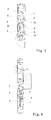
Fig. 3 is a sectional view along line C-C inFig. 1 ; -
Fig. 4 is a sectional view along line B-B inFig. 1 ; and -
Fig. 5 is a prospective schematic view of the connecting rod of the air deflector drive means shown inFig. 1 . - Explanation of Reference Numbers: 1-box body; 11-protruding opening; 12, 13, 14, 15-pillar; 16, 17-limiting post; 2-box cover; 3-connecting rod; 31-head end of the connecting rod; 32-tail end of the connecting rod; 33-rack; 34-chute guide rail; 35-slide groove; 36-edge of the connecting rod; 4-main gear; 5-bearing pad; 6-limiting groove; A-first limiting member; B-second limiting member; C-third limiting member; D-fourth limiting member.
- Hereinafter, the embodiments of the present utility model will be described in detail, referring to the figures.
- Referring to
Figs. 1 and 2 , in one embodiment of the present utility model, the connecting rod limiting means is mainly composed of a drive box and a limiting structure provided in the drive box. The drive box is constituted of abox body 1 and abox cover 2. Thebox body 1 is provided with a protruding opening 11 and the limiting structure. The connectingrod 3 is slidably provided in the drive box. Thetail end 32 of the connecting rod is provided with arack 33 which is engaged with amain gear 4 mounted in the drive box, and thetip end 31 of the connecting rod protrudes from the protrudingopening 11. The telescoping movement of the connectingrod 3 is achieved by means of the forward and backward rotation of a motor. The displacement of the connectingrod 3 in the up, down, left and right directions during the movement is limited by means of the limiting structure, such that the connectingrod 3 can stably work during the telescoping movement, achieving the stable working of the air deflector. The limiting structure of the present embodiment can be divided to three limiting points: first, second and third limiting points. - Referring to
Fig. 1 , the first limiting point is composed of a first limiting member A and a second limiting member B each of which is close to the protruding opening 11 and located on either side of the connectingrod 3 respectively. Further referring toFig. 3 , the first limiting member A is composed of apillar 12 and a rolling member sleeved over thepillar 12. The rolling member is provided with alimiting groove 6 matching with the edge of the connectingrod 3. The first limiting member A and the second limiting member B respectively limit the up and down displacements of the connectingrod 3 during the movement from both sides, making it work stably. Meanwhile, after thebox body 1 and thebox cover 2 are snapped together, thelimiting groove 6 limits the movement of the connectingrod 3 towards the left and right directions during the movement, in order to avoid the connectingrod 3 swaying leftward and rightward. Preferably, the rolling member is constituted by two stepped bearingpads 5. During assembly, firstly abearing pad 5 is mounted onto thepillar 12 on one side, then the connectingrod 3 is mounted into thebox body 1, and subsequently abearing pad 5 is mounted on the other side, so as to facilitate the assembly. The second limiting member B, which has the same structure as the first limiting member A, is composed of apillar 13 and twobearing pads 5 sleeved over thepillar 13. The redundant description is omitted. - The second limiting point is composed of a third limiting member C and a fourth limiting member D. The tail of the connecting
rod 3 is provided with achute guide rail 34 extending along the moving direction of the connectingrod 3. The third limiting member C is arranged to pass through thechute guide rail 34 and cooperation therewith. The fourth limiting member D is provided on the lower side of the connectingrod 3 opposite to the third limiting member C. The third limiting member C and the fourth limiting member D limit in combination the upward and downward displacements of the connectingrod 3 during the movement. Referring toFig. 4 , the third limiting member C, which has the same structure as the first limiting member A, is composed of apillar 14 and twobearing pads 5 sleeved over the pillar. The third limiting member C, which has the same structure as the first limiting member A, is composed of apillar 15 and twobearing pads 5 sleeved over the pillar. The redundant description is omitted. - The third limiting point is composed of two limiting
posts rod 3. Referring toFig. 5 , aslide groove 35 running through the surface of the connectingrod 3 is provided on the surface of a side of the connectingrod 3 facing thelimiting posts limiting posts slide groove 35, in order to limit the position in up and down direction and support the tail end of the connectingrod 3. - Hereinafter, the working principle of the present embodiment is further described.
- During the movement of the connecting
rod 3, the telescoping trajectory of the connectingrod 3 is based on a preset track. When the connectingrod 3 is protruding out, themain gear 4 rotates to drive therack 3 to move, and at the same time, thebearing pads 5 rotate and thepillars rod 3, making it work stably. The moving angle is controlled by the rotating angle of the stepping motor which is controlled by a preset program. When protruding to rotate to a certain angle, the connecting rod is stopped. When the connectingrod 3 moves to the front half portion, the first limiting point and the second limiting point assure in combination the position in up and down direction of the connectingrod 3 and prevent it from playing and being displaced leftwards and rightwards, such that it protrudes smoothly, up to the extreme position. - After the connecting
rod 3 protrudes to the extreme position, a microswitch is triggered to make the motor rotate reversely, so as to drive themain gear 4 to rotate reversely. When the connectingrod 3 contracts to the rear half portion, the stability of the rear portion of the connectingrod 3 is achieved by means of the second limiting point and the third limiting point which limit in combination the movement in the up and down direction. At the same time, the front end of the connectingrod 3 is still limited by the first limiting point. - Obviously, with the limiting means of the connecting
rod 3, the connectingrod 3 is limited by the three limiting points in combination, guaranteeing the connectingrod 3 stable in left, right, up and down directions. - The above description only relates to specific embodiments of the present utility model, is not intended to limit the protection scope of the present utility model. Without departing the concept of the present utility model, any substitutions and improvements are covered by the protection scope of the present utility model.
Claims (10)
- An air deflector drive means, comprising a drive case and a connecting rod, wherein one side of the drive case is provided with a protruding opening, the connecting rod is slidably disposed in the drive case, the tip of the connection rod protrudes from the protruding opening, characterized in that the drive case is provided therein with a limiting structure by means of which the displacement of the connecting rod in the direction perpendicular to the moving direction of the connecting rod is limited.
- The air deflector drive means according to claim 1, characterized in that the limiting structure comprises a first limiting member and a second limiting member, with the first limiting member and the second limiting member close to the protruding opening and located at either side of the connecting rod respectively.
- The air deflector drive means according to claim 2, characterized in that the first limiting member and the second limiting member each comprises a pillar and a rolling member sleeved over the pillar, and the rolling member is provided with a limiting groove matching with the edge of the connection rod.
- The air deflector drive means according to claim 3, characterized in that the rolling member is constituted by two stepped bearing pads.
- The air deflector drive means according to claim 1, characterized in that the connection rod is provided at its tail portion with a chute guide rail extending along the moving direction of the connecting rod; the limiting structure comprises a third limiting member and a fourth limiting member, the third limiting member is arranged to pass through the chute guide rail and cooperate therewith, and the fourth limiting member is provided on a side of the connecting rod opposite to the third limiting member.
- The air deflector drive means according to claim 5, characterized in that the third limiting member and the fourth limiting member each comprises a pillar and a rolling member sleeved over the pillar, and the rolling member is provided with a limiting groove matching with the edge of the connection rod.
- The air deflector drive means according to claim 6, characterized in that the rolling member is constituted by two stepped bearing pads.
- The air deflector drive means according to any one of claims 1-7, characterized in that the limiting structure further comprises at least one limiting post provided along the moving direction of the connecting rod, a slide groove running through the surface of the connecting rod is provided on the surface of a side of the connecting rod facing the limiting post, and the limiting post is in cooperation with the slide groove.
- The air deflector drive means according to claim 8, characterized in that the drive case comprises a box body and a box cover in snap-fit, and the limiting structure is provided on the box body.
- An indoor air-conditioning unit, comprising an air deflector and an air deflector drive means according to any one of Claims 1-9, wherein the tip of the connecting rod is connected with the air deflector.
Applications Claiming Priority (2)
| Application Number | Priority Date | Filing Date | Title |
|---|---|---|---|
| CN2012200705649U CN202470348U (en) | 2012-02-29 | 2012-02-29 | Wind deflector driving device and air conditioner indoor unit using the driving device |
| PCT/CN2013/071287 WO2013127290A1 (en) | 2012-02-29 | 2013-02-01 | Air deflector drive means and indoor air-conditioning unit using drive means |
Publications (3)
| Publication Number | Publication Date |
|---|---|
| EP2821715A1 true EP2821715A1 (en) | 2015-01-07 |
| EP2821715A4 EP2821715A4 (en) | 2015-04-29 |
| EP2821715B1 EP2821715B1 (en) | 2018-01-17 |
Family
ID=46918503
Family Applications (1)
| Application Number | Title | Priority Date | Filing Date |
|---|---|---|---|
| EP13755737.7A Active EP2821715B1 (en) | 2012-02-29 | 2013-02-01 | Air deflector drive means and indoor air-conditioning unit using drive means |
Country Status (10)
| Country | Link |
|---|---|
| US (1) | US9829211B2 (en) |
| EP (1) | EP2821715B1 (en) |
| JP (1) | JP3196141U (en) |
| KR (1) | KR200482124Y1 (en) |
| CN (1) | CN202470348U (en) |
| AU (1) | AU2013225554B2 (en) |
| BR (1) | BR112014021396B1 (en) |
| CA (1) | CA2865471C (en) |
| IN (1) | IN2014KN01666A (en) |
| WO (1) | WO2013127290A1 (en) |
Cited By (1)
| Publication number | Priority date | Publication date | Assignee | Title |
|---|---|---|---|---|
| CN106766063A (en) * | 2016-12-16 | 2017-05-31 | 珠海格力电器股份有限公司 | Driving box subassembly and air conditioner |
Families Citing this family (22)
| Publication number | Priority date | Publication date | Assignee | Title |
|---|---|---|---|---|
| CN202470348U (en) * | 2012-02-29 | 2012-10-03 | 珠海格力电器股份有限公司 | Wind deflector driving device and air conditioner indoor unit using the driving device |
| KR102152645B1 (en) * | 2013-09-17 | 2020-09-08 | 삼성전자주식회사 | Air conditional |
| CN203518158U (en) * | 2013-10-22 | 2014-04-02 | 珠海格力电器股份有限公司 | Air deflector driving device and air conditioner with same |
| CN103557584B (en) * | 2013-11-18 | 2016-03-30 | 四川长虹空调有限公司 | Hanging type air conditioner and air conditioning air flow control method |
| KR102217011B1 (en) * | 2014-02-11 | 2021-02-19 | 삼성전자주식회사 | Air conditional |
| CN104034008B (en) * | 2014-06-06 | 2016-07-06 | 珠海格力电器股份有限公司 | Door plate driving box of air conditioner and air conditioner |
| USD795917S1 (en) | 2015-05-17 | 2017-08-29 | Google Inc. | Display screen with an animated graphical user interface |
| CN105402873B (en) * | 2015-12-09 | 2019-04-26 | 珠海格力电器股份有限公司 | Aviation baffle actuating mechanism and air conditioner hanging machine |
| CN105781311B (en) * | 2016-01-04 | 2017-10-31 | 珠海格力电器股份有限公司 | Sports device and electrical equipment |
| CN105546658A (en) * | 2016-02-01 | 2016-05-04 | 珠海格力电器股份有限公司 | Air conditioner indoor unit and air conditioner with same |
| CN105953393A (en) * | 2016-06-24 | 2016-09-21 | 宁波奥克斯空调有限公司 | Moving mechanism for air conditioner sliding door |
| CN106195178B (en) * | 2016-07-18 | 2019-04-02 | 珠海格力电器股份有限公司 | Drive box device and air conditioner wall hanging machine |
| CN106225195A (en) * | 2016-09-09 | 2016-12-14 | 珠海格力电器股份有限公司 | Air conditioner air port plate adjusting mechanism and air conditioner with same |
| CN106352413A (en) * | 2016-11-01 | 2017-01-25 | 珠海格力电器股份有限公司 | Air conditioner, air conditioner indoor unit and air deflector driving device thereof |
| CN108489064B (en) * | 2018-05-07 | 2023-07-14 | 珠海格力电器股份有限公司 | Air-out structure and have its air conditioner |
| CN108488932B (en) * | 2018-06-19 | 2023-07-14 | 珠海格力电器股份有限公司 | air conditioner |
| CN110220291B (en) * | 2019-07-19 | 2024-09-06 | 珠海格力电器股份有限公司 | Air guide mechanism and air conditioner |
| CN110986157B (en) * | 2019-10-28 | 2021-09-21 | 青岛海尔空调器有限总公司 | Air conditioner indoor unit and air conditioner |
| CN111006315B (en) * | 2019-12-05 | 2022-04-19 | 青岛海尔空调器有限总公司 | Air conditioner indoor unit |
| US20230408137A1 (en) * | 2020-10-30 | 2023-12-21 | Gd Midea Air-Conditioning Equipment Co., Ltd. | Driver mechanism for air defection mechanism, air defection mechanism, and air conditioner |
| CN115111758A (en) * | 2021-03-19 | 2022-09-27 | 青岛海尔智能技术研发有限公司 | A machine in drive assembly, air conditioning for aviation baffle |
| CN113654229A (en) * | 2021-08-20 | 2021-11-16 | 珠海格力电器股份有限公司 | Driving mechanism, air deflector assembly and air conditioner |
Family Cites Families (25)
| Publication number | Priority date | Publication date | Assignee | Title |
|---|---|---|---|---|
| KR100215048B1 (en) * | 1996-03-21 | 1999-08-16 | 윤종용 | Discharge port opening and closing device of air conditioner |
| AU6159499A (en) * | 1998-09-29 | 2000-04-17 | Wyeth Holdings Corporation | Substituted 3-cyanoquinolines as protein tyrosine kinases inhibitors |
| KR100365591B1 (en) * | 2000-06-12 | 2002-12-26 | 삼성전자 주식회사 | Opening and closing apparatus for air discharge port of air conditioner |
| AU2002314572A1 (en) * | 2001-06-19 | 2003-01-02 | Lg Electronics Inc. | Air conditioner |
| JP3780974B2 (en) * | 2002-05-13 | 2006-05-31 | 松下電器産業株式会社 | Air conditioner wind direction change device |
| US8074462B2 (en) * | 2004-07-14 | 2011-12-13 | Daikin Industries, Ltd. | Indoor unit of an air conditioner having variable intake suction port |
| EP1778385B1 (en) * | 2004-08-16 | 2009-08-05 | LG Electronics, Inc. | Filter unit of air conditioner |
| JP3806881B2 (en) * | 2004-11-08 | 2006-08-09 | ダイキン工業株式会社 | Indoor unit of air conditioner |
| AU2005326876B8 (en) * | 2005-01-11 | 2009-05-14 | Lg Electronics Inc. | Air conditioner |
| BRPI0518503A2 (en) * | 2005-01-26 | 2008-12-02 | Lg Electronics Inc | air conditioner |
| CA2625690C (en) * | 2005-10-24 | 2012-05-22 | Camfil Farr, Inc. | Linear drive for integrated damper |
| TWM292681U (en) * | 2005-12-19 | 2006-06-21 | Coochingchi Pong | Base structure of a cold and warm air conditioner |
| KR100724389B1 (en) * | 2005-12-29 | 2007-06-04 | 엘지전자 주식회사 | Outdoor unit of air conditioner with discharge door |
| WO2007142957A2 (en) * | 2006-05-30 | 2007-12-13 | Air Systems | Gear drive damper |
| EP1950501A1 (en) * | 2007-01-29 | 2008-07-30 | Lg Electronics Inc. | Air conditioner |
| JP4237238B1 (en) | 2007-09-07 | 2009-03-11 | シャープ株式会社 | Air conditioner |
| US20090149123A1 (en) * | 2007-12-11 | 2009-06-11 | Randy Blagg | Register for air conditioning |
| JP5136122B2 (en) * | 2008-03-05 | 2013-02-06 | パナソニック株式会社 | Louver device |
| CN201246855Y (en) * | 2008-07-04 | 2009-05-27 | 广东美的电器股份有限公司 | Wind guide mechanism of split wall hanging type air conditioner indoor machine |
| KR101065830B1 (en) * | 2008-12-29 | 2011-09-20 | 엘지전자 주식회사 | Ceiling air conditioners |
| JP5470084B2 (en) * | 2010-02-17 | 2014-04-16 | 株式会社ケーヒン | Sliding door device |
| CN102192581B (en) * | 2010-03-03 | 2013-04-03 | 珠海格力电器股份有限公司 | Driving device for air deflector assembly and air conditioner comprising same |
| KR101781845B1 (en) * | 2010-05-13 | 2017-09-26 | 엘지전자 주식회사 | Indoor unit of air conditioner |
| CN101858641B (en) * | 2010-06-18 | 2012-05-30 | 广东志高空调有限公司 | Cabinet air conditioner air-out structure |
| CN202470348U (en) * | 2012-02-29 | 2012-10-03 | 珠海格力电器股份有限公司 | Wind deflector driving device and air conditioner indoor unit using the driving device |
-
2012
- 2012-02-29 CN CN2012200705649U patent/CN202470348U/en not_active Expired - Lifetime
-
2013
- 2013-02-01 WO PCT/CN2013/071287 patent/WO2013127290A1/en not_active Ceased
- 2013-02-01 CA CA2865471A patent/CA2865471C/en active Active
- 2013-02-01 BR BR112014021396-8A patent/BR112014021396B1/en active IP Right Grant
- 2013-02-01 IN IN1666KON2014 patent/IN2014KN01666A/en unknown
- 2013-02-01 AU AU2013225554A patent/AU2013225554B2/en active Active
- 2013-02-01 JP JP2014600098U patent/JP3196141U/en not_active Expired - Lifetime
- 2013-02-01 EP EP13755737.7A patent/EP2821715B1/en active Active
- 2013-02-01 US US14/380,879 patent/US9829211B2/en active Active
- 2013-02-01 KR KR2020147000042U patent/KR200482124Y1/en not_active Expired - Lifetime
Cited By (1)
| Publication number | Priority date | Publication date | Assignee | Title |
|---|---|---|---|---|
| CN106766063A (en) * | 2016-12-16 | 2017-05-31 | 珠海格力电器股份有限公司 | Driving box subassembly and air conditioner |
Also Published As
| Publication number | Publication date |
|---|---|
| US20150011155A1 (en) | 2015-01-08 |
| EP2821715A4 (en) | 2015-04-29 |
| AU2013225554A1 (en) | 2014-09-04 |
| IN2014KN01666A (en) | 2015-10-23 |
| JP3196141U (en) | 2015-02-26 |
| EP2821715B1 (en) | 2018-01-17 |
| BR112014021396A8 (en) | 2021-10-13 |
| KR20140005665U (en) | 2014-11-04 |
| KR200482124Y1 (en) | 2016-12-16 |
| BR112014021396A2 (en) | 2017-08-22 |
| CN202470348U (en) | 2012-10-03 |
| AU2013225554B2 (en) | 2016-08-11 |
| CA2865471A1 (en) | 2013-09-06 |
| WO2013127290A1 (en) | 2013-09-06 |
| BR112014021396B1 (en) | 2023-03-28 |
| CA2865471C (en) | 2019-12-31 |
| US9829211B2 (en) | 2017-11-28 |
Similar Documents
| Publication | Publication Date | Title |
|---|---|---|
| EP2821715B1 (en) | Air deflector drive means and indoor air-conditioning unit using drive means | |
| JP5799734B2 (en) | Air conditioning system for passenger cars | |
| CN215637539U (en) | Air conditioner indoor unit | |
| CN106871410A (en) | Wind deflector drive mechanism and air-conditioner | |
| CN102313347A (en) | Air conditioner and air conditioner indoor unit | |
| CN106352405A (en) | Movable door assembly of air conditioner indoor unit and air conditioner indoor unit | |
| CN206320854U (en) | A kind of air exhausting structure and air-conditioner | |
| CN106594880A (en) | Indoor unit of air conditioner | |
| BRPI0909384B1 (en) | wire forming machine forming station with ring tool holder | |
| CN105783222B (en) | Air deflector assembly and air conditioner | |
| CN205651338U (en) | Swing arm moving mechanical arm | |
| CN207711949U (en) | A kind of farm machinery navigation display screen driving device | |
| CN104501383B (en) | Air supply device and air conditioner | |
| CN203375632U (en) | Air-conditioner wind deflector and air-conditioner | |
| CN213577768U (en) | Indoor unit of air conditioner | |
| CN109677913A (en) | A kind of carrying telescoping mechanism and handling device | |
| CN208614774U (en) | A parallel mechanism with two rotations and one movement with three degrees of freedom driven in parallel | |
| CN104455283B (en) | A kind of mobile controller overturning structure | |
| CN217031562U (en) | Limiting device for movement of air conditioner panel and air conditioner | |
| CN207006492U (en) | Drive mechanism and air conditioner | |
| EP3779294A1 (en) | Blade adjusting mechanism and air circulator | |
| CN206478819U (en) | Indoor apparatus of air conditioner | |
| CN214868232U (en) | A welding head clamping moving device and automatic welding machine | |
| CN209263299U (en) | panel driving mechanism, air conditioner shell and air conditioner | |
| CN211727957U (en) | Simple laser cutting equipment |
Legal Events
| Date | Code | Title | Description |
|---|---|---|---|
| PUAI | Public reference made under article 153(3) epc to a published international application that has entered the european phase |
Free format text: ORIGINAL CODE: 0009012 |
|
| 17P | Request for examination filed |
Effective date: 20140804 |
|
| AK | Designated contracting states |
Kind code of ref document: A1 Designated state(s): AL AT BE BG CH CY CZ DE DK EE ES FI FR GB GR HR HU IE IS IT LI LT LU LV MC MK MT NL NO PL PT RO RS SE SI SK SM TR |
|
| AX | Request for extension of the european patent |
Extension state: BA ME |
|
| RA4 | Supplementary search report drawn up and despatched (corrected) |
Effective date: 20150331 |
|
| RIC1 | Information provided on ipc code assigned before grant |
Ipc: F24F 13/14 20060101ALI20150325BHEP Ipc: F24F 13/08 20060101ALI20150325BHEP Ipc: F24F 1/00 20110101AFI20150325BHEP |
|
| RIN1 | Information on inventor provided before grant (corrected) |
Inventor name: ZHANG, HUI Inventor name: WANG, XIANLIN Inventor name: MENG, ZHI Inventor name: CHEN, SHAOLIN |
|
| DAX | Request for extension of the european patent (deleted) | ||
| GRAP | Despatch of communication of intention to grant a patent |
Free format text: ORIGINAL CODE: EPIDOSNIGR1 |
|
| INTG | Intention to grant announced |
Effective date: 20170816 |
|
| GRAS | Grant fee paid |
Free format text: ORIGINAL CODE: EPIDOSNIGR3 |
|
| GRAA | (expected) grant |
Free format text: ORIGINAL CODE: 0009210 |
|
| AK | Designated contracting states |
Kind code of ref document: B1 Designated state(s): AL AT BE BG CH CY CZ DE DK EE ES FI FR GB GR HR HU IE IS IT LI LT LU LV MC MK MT NL NO PL PT RO RS SE SI SK SM TR |
|
| REG | Reference to a national code |
Ref country code: GB Ref legal event code: FG4D |
|
| REG | Reference to a national code |
Ref country code: FR Ref legal event code: PLFP Year of fee payment: 6 Ref country code: CH Ref legal event code: EP |
|
| REG | Reference to a national code |
Ref country code: IE Ref legal event code: FG4D |
|
| REG | Reference to a national code |
Ref country code: AT Ref legal event code: REF Ref document number: 964690 Country of ref document: AT Kind code of ref document: T Effective date: 20180215 |
|
| REG | Reference to a national code |
Ref country code: DE Ref legal event code: R096 Ref document number: 602013032345 Country of ref document: DE |
|
| REG | Reference to a national code |
Ref country code: NL Ref legal event code: MP Effective date: 20180117 |
|
| REG | Reference to a national code |
Ref country code: LT Ref legal event code: MG4D |
|
| REG | Reference to a national code |
Ref country code: AT Ref legal event code: MK05 Ref document number: 964690 Country of ref document: AT Kind code of ref document: T Effective date: 20180117 |
|
| PG25 | Lapsed in a contracting state [announced via postgrant information from national office to epo] |
Ref country code: NL Free format text: LAPSE BECAUSE OF FAILURE TO SUBMIT A TRANSLATION OF THE DESCRIPTION OR TO PAY THE FEE WITHIN THE PRESCRIBED TIME-LIMIT Effective date: 20180117 |
|
| PG25 | Lapsed in a contracting state [announced via postgrant information from national office to epo] |
Ref country code: ES Free format text: LAPSE BECAUSE OF FAILURE TO SUBMIT A TRANSLATION OF THE DESCRIPTION OR TO PAY THE FEE WITHIN THE PRESCRIBED TIME-LIMIT Effective date: 20180117 Ref country code: CY Free format text: LAPSE BECAUSE OF FAILURE TO SUBMIT A TRANSLATION OF THE DESCRIPTION OR TO PAY THE FEE WITHIN THE PRESCRIBED TIME-LIMIT Effective date: 20180117 Ref country code: LT Free format text: LAPSE BECAUSE OF FAILURE TO SUBMIT A TRANSLATION OF THE DESCRIPTION OR TO PAY THE FEE WITHIN THE PRESCRIBED TIME-LIMIT Effective date: 20180117 Ref country code: NO Free format text: LAPSE BECAUSE OF FAILURE TO SUBMIT A TRANSLATION OF THE DESCRIPTION OR TO PAY THE FEE WITHIN THE PRESCRIBED TIME-LIMIT Effective date: 20180417 Ref country code: FI Free format text: LAPSE BECAUSE OF FAILURE TO SUBMIT A TRANSLATION OF THE DESCRIPTION OR TO PAY THE FEE WITHIN THE PRESCRIBED TIME-LIMIT Effective date: 20180117 Ref country code: HR Free format text: LAPSE BECAUSE OF FAILURE TO SUBMIT A TRANSLATION OF THE DESCRIPTION OR TO PAY THE FEE WITHIN THE PRESCRIBED TIME-LIMIT Effective date: 20180117 |
|
| PG25 | Lapsed in a contracting state [announced via postgrant information from national office to epo] |
Ref country code: RS Free format text: LAPSE BECAUSE OF FAILURE TO SUBMIT A TRANSLATION OF THE DESCRIPTION OR TO PAY THE FEE WITHIN THE PRESCRIBED TIME-LIMIT Effective date: 20180117 Ref country code: GR Free format text: LAPSE BECAUSE OF FAILURE TO SUBMIT A TRANSLATION OF THE DESCRIPTION OR TO PAY THE FEE WITHIN THE PRESCRIBED TIME-LIMIT Effective date: 20180418 Ref country code: AT Free format text: LAPSE BECAUSE OF FAILURE TO SUBMIT A TRANSLATION OF THE DESCRIPTION OR TO PAY THE FEE WITHIN THE PRESCRIBED TIME-LIMIT Effective date: 20180117 Ref country code: PL Free format text: LAPSE BECAUSE OF FAILURE TO SUBMIT A TRANSLATION OF THE DESCRIPTION OR TO PAY THE FEE WITHIN THE PRESCRIBED TIME-LIMIT Effective date: 20180117 Ref country code: LV Free format text: LAPSE BECAUSE OF FAILURE TO SUBMIT A TRANSLATION OF THE DESCRIPTION OR TO PAY THE FEE WITHIN THE PRESCRIBED TIME-LIMIT Effective date: 20180117 Ref country code: BG Free format text: LAPSE BECAUSE OF FAILURE TO SUBMIT A TRANSLATION OF THE DESCRIPTION OR TO PAY THE FEE WITHIN THE PRESCRIBED TIME-LIMIT Effective date: 20180417 Ref country code: IS Free format text: LAPSE BECAUSE OF FAILURE TO SUBMIT A TRANSLATION OF THE DESCRIPTION OR TO PAY THE FEE WITHIN THE PRESCRIBED TIME-LIMIT Effective date: 20180517 Ref country code: SE Free format text: LAPSE BECAUSE OF FAILURE TO SUBMIT A TRANSLATION OF THE DESCRIPTION OR TO PAY THE FEE WITHIN THE PRESCRIBED TIME-LIMIT Effective date: 20180117 |
|
| REG | Reference to a national code |
Ref country code: CH Ref legal event code: PL |
|
| REG | Reference to a national code |
Ref country code: DE Ref legal event code: R097 Ref document number: 602013032345 Country of ref document: DE |
|
| PG25 | Lapsed in a contracting state [announced via postgrant information from national office to epo] |
Ref country code: RO Free format text: LAPSE BECAUSE OF FAILURE TO SUBMIT A TRANSLATION OF THE DESCRIPTION OR TO PAY THE FEE WITHIN THE PRESCRIBED TIME-LIMIT Effective date: 20180117 Ref country code: MC Free format text: LAPSE BECAUSE OF FAILURE TO SUBMIT A TRANSLATION OF THE DESCRIPTION OR TO PAY THE FEE WITHIN THE PRESCRIBED TIME-LIMIT Effective date: 20180117 Ref country code: AL Free format text: LAPSE BECAUSE OF FAILURE TO SUBMIT A TRANSLATION OF THE DESCRIPTION OR TO PAY THE FEE WITHIN THE PRESCRIBED TIME-LIMIT Effective date: 20180117 Ref country code: EE Free format text: LAPSE BECAUSE OF FAILURE TO SUBMIT A TRANSLATION OF THE DESCRIPTION OR TO PAY THE FEE WITHIN THE PRESCRIBED TIME-LIMIT Effective date: 20180117 Ref country code: IT Free format text: LAPSE BECAUSE OF FAILURE TO SUBMIT A TRANSLATION OF THE DESCRIPTION OR TO PAY THE FEE WITHIN THE PRESCRIBED TIME-LIMIT Effective date: 20180117 |
|
| PLBE | No opposition filed within time limit |
Free format text: ORIGINAL CODE: 0009261 |
|
| STAA | Information on the status of an ep patent application or granted ep patent |
Free format text: STATUS: NO OPPOSITION FILED WITHIN TIME LIMIT |
|
| REG | Reference to a national code |
Ref country code: IE Ref legal event code: MM4A |
|
| REG | Reference to a national code |
Ref country code: BE Ref legal event code: MM Effective date: 20180228 |
|
| PG25 | Lapsed in a contracting state [announced via postgrant information from national office to epo] |
Ref country code: DK Free format text: LAPSE BECAUSE OF FAILURE TO SUBMIT A TRANSLATION OF THE DESCRIPTION OR TO PAY THE FEE WITHIN THE PRESCRIBED TIME-LIMIT Effective date: 20180117 Ref country code: CH Free format text: LAPSE BECAUSE OF NON-PAYMENT OF DUE FEES Effective date: 20180228 Ref country code: SM Free format text: LAPSE BECAUSE OF FAILURE TO SUBMIT A TRANSLATION OF THE DESCRIPTION OR TO PAY THE FEE WITHIN THE PRESCRIBED TIME-LIMIT Effective date: 20180117 Ref country code: SK Free format text: LAPSE BECAUSE OF FAILURE TO SUBMIT A TRANSLATION OF THE DESCRIPTION OR TO PAY THE FEE WITHIN THE PRESCRIBED TIME-LIMIT Effective date: 20180117 Ref country code: CZ Free format text: LAPSE BECAUSE OF FAILURE TO SUBMIT A TRANSLATION OF THE DESCRIPTION OR TO PAY THE FEE WITHIN THE PRESCRIBED TIME-LIMIT Effective date: 20180117 Ref country code: LI Free format text: LAPSE BECAUSE OF NON-PAYMENT OF DUE FEES Effective date: 20180228 Ref country code: LU Free format text: LAPSE BECAUSE OF NON-PAYMENT OF DUE FEES Effective date: 20180201 |
|
| 26N | No opposition filed |
Effective date: 20181018 |
|
| PG25 | Lapsed in a contracting state [announced via postgrant information from national office to epo] |
Ref country code: IE Free format text: LAPSE BECAUSE OF NON-PAYMENT OF DUE FEES Effective date: 20180201 |
|
| PG25 | Lapsed in a contracting state [announced via postgrant information from national office to epo] |
Ref country code: SI Free format text: LAPSE BECAUSE OF FAILURE TO SUBMIT A TRANSLATION OF THE DESCRIPTION OR TO PAY THE FEE WITHIN THE PRESCRIBED TIME-LIMIT Effective date: 20180117 Ref country code: BE Free format text: LAPSE BECAUSE OF NON-PAYMENT OF DUE FEES Effective date: 20180228 |
|
| PG25 | Lapsed in a contracting state [announced via postgrant information from national office to epo] |
Ref country code: MT Free format text: LAPSE BECAUSE OF NON-PAYMENT OF DUE FEES Effective date: 20180201 |
|
| PG25 | Lapsed in a contracting state [announced via postgrant information from national office to epo] |
Ref country code: TR Free format text: LAPSE BECAUSE OF FAILURE TO SUBMIT A TRANSLATION OF THE DESCRIPTION OR TO PAY THE FEE WITHIN THE PRESCRIBED TIME-LIMIT Effective date: 20180117 |
|
| PG25 | Lapsed in a contracting state [announced via postgrant information from national office to epo] |
Ref country code: PT Free format text: LAPSE BECAUSE OF FAILURE TO SUBMIT A TRANSLATION OF THE DESCRIPTION OR TO PAY THE FEE WITHIN THE PRESCRIBED TIME-LIMIT Effective date: 20180117 Ref country code: HU Free format text: LAPSE BECAUSE OF FAILURE TO SUBMIT A TRANSLATION OF THE DESCRIPTION OR TO PAY THE FEE WITHIN THE PRESCRIBED TIME-LIMIT; INVALID AB INITIO Effective date: 20130201 |
|
| PG25 | Lapsed in a contracting state [announced via postgrant information from national office to epo] |
Ref country code: MK Free format text: LAPSE BECAUSE OF NON-PAYMENT OF DUE FEES Effective date: 20180117 |
|
| P01 | Opt-out of the competence of the unified patent court (upc) registered |
Effective date: 20230530 |
|
| PGFP | Annual fee paid to national office [announced via postgrant information from national office to epo] |
Ref country code: GB Payment date: 20260120 Year of fee payment: 14 |
|
| PGFP | Annual fee paid to national office [announced via postgrant information from national office to epo] |
Ref country code: DE Payment date: 20260217 Year of fee payment: 14 |
|
| PGFP | Annual fee paid to national office [announced via postgrant information from national office to epo] |
Ref country code: FR Payment date: 20260119 Year of fee payment: 14 |