EP2821601A2 - Engine - Google Patents
Engine Download PDFInfo
- Publication number
- EP2821601A2 EP2821601A2 EP13191020.0A EP13191020A EP2821601A2 EP 2821601 A2 EP2821601 A2 EP 2821601A2 EP 13191020 A EP13191020 A EP 13191020A EP 2821601 A2 EP2821601 A2 EP 2821601A2
- Authority
- EP
- European Patent Office
- Prior art keywords
- section
- cam
- shaft
- cylinder
- rocker arm
- Prior art date
- Legal status (The legal status is an assumption and is not a legal conclusion. Google has not performed a legal analysis and makes no representation as to the accuracy of the status listed.)
- Granted
Links
- 238000002485 combustion reaction Methods 0.000 claims description 9
- 238000010586 diagram Methods 0.000 description 27
- XLYOFNOQVPJJNP-UHFFFAOYSA-N water Substances O XLYOFNOQVPJJNP-UHFFFAOYSA-N 0.000 description 7
- 239000000110 cooling liquid Substances 0.000 description 3
- 238000000034 method Methods 0.000 description 3
- 230000000994 depressogenic effect Effects 0.000 description 2
- 230000005611 electricity Effects 0.000 description 2
- 239000000446 fuel Substances 0.000 description 2
- 230000000694 effects Effects 0.000 description 1
- 230000002452 interceptive effect Effects 0.000 description 1
- 238000012986 modification Methods 0.000 description 1
- 230000004048 modification Effects 0.000 description 1
Images


Classifications
-
- F—MECHANICAL ENGINEERING; LIGHTING; HEATING; WEAPONS; BLASTING
- F01—MACHINES OR ENGINES IN GENERAL; ENGINE PLANTS IN GENERAL; STEAM ENGINES
- F01L—CYCLICALLY OPERATING VALVES FOR MACHINES OR ENGINES
- F01L13/00—Modifications of valve-gear to facilitate reversing, braking, starting, changing compression ratio, or other specific operations
- F01L13/0015—Modifications of valve-gear to facilitate reversing, braking, starting, changing compression ratio, or other specific operations for optimising engine performances by modifying valve lift according to various working parameters, e.g. rotational speed, load, torque
- F01L13/0036—Modifications of valve-gear to facilitate reversing, braking, starting, changing compression ratio, or other specific operations for optimising engine performances by modifying valve lift according to various working parameters, e.g. rotational speed, load, torque the valves being driven by two or more cams with different shape, size or timing or a single cam profiled in axial and radial direction
-
- F—MECHANICAL ENGINEERING; LIGHTING; HEATING; WEAPONS; BLASTING
- F01—MACHINES OR ENGINES IN GENERAL; ENGINE PLANTS IN GENERAL; STEAM ENGINES
- F01L—CYCLICALLY OPERATING VALVES FOR MACHINES OR ENGINES
- F01L1/00—Valve-gear or valve arrangements, e.g. lift-valve gear
- F01L1/26—Valve-gear or valve arrangements, e.g. lift-valve gear characterised by the provision of two or more valves operated simultaneously by same transmitting-gear; peculiar to machines or engines with more than two lift-valves per cylinder
- F01L1/267—Valve-gear or valve arrangements, e.g. lift-valve gear characterised by the provision of two or more valves operated simultaneously by same transmitting-gear; peculiar to machines or engines with more than two lift-valves per cylinder with means for varying the timing or the lift of the valves
-
- F—MECHANICAL ENGINEERING; LIGHTING; HEATING; WEAPONS; BLASTING
- F02—COMBUSTION ENGINES; HOT-GAS OR COMBUSTION-PRODUCT ENGINE PLANTS
- F02B—INTERNAL-COMBUSTION PISTON ENGINES; COMBUSTION ENGINES IN GENERAL
- F02B75/00—Other engines
- F02B75/16—Engines characterised by number of cylinders, e.g. single-cylinder engines
-
- F—MECHANICAL ENGINEERING; LIGHTING; HEATING; WEAPONS; BLASTING
- F01—MACHINES OR ENGINES IN GENERAL; ENGINE PLANTS IN GENERAL; STEAM ENGINES
- F01L—CYCLICALLY OPERATING VALVES FOR MACHINES OR ENGINES
- F01L1/00—Valve-gear or valve arrangements, e.g. lift-valve gear
- F01L1/02—Valve drive
- F01L1/04—Valve drive by means of cams, camshafts, cam discs, eccentrics or the like
- F01L1/047—Camshafts
- F01L1/053—Camshafts overhead type
- F01L2001/0535—Single overhead camshafts [SOHC]
Landscapes
- Engineering & Computer Science (AREA)
- Mechanical Engineering (AREA)
- General Engineering & Computer Science (AREA)
- Chemical & Material Sciences (AREA)
- Combustion & Propulsion (AREA)
- Valve Device For Special Equipments (AREA)
- Valve-Gear Or Valve Arrangements (AREA)
Abstract
Description
- The present invention relates to an engine.
- A SOHC (Single OverHead Camshaft) engine is known which is provided with a variable valve gear where switching between linking or not linking of a plurality of rocker arms is possible by a pin member which links the rocker arms being directly pressurized by an actuator. For example, in an engine described in Japan Patent Laid-open Patent Publication
JP-A-2012-77741 - The engine described above is a so-called SOHC engine. Essentially, it is possible to arrange a valve gear in a SOHC engine in a compact manner. However, in the engine described above, a variable valve gear is realized with a simple configuration by adopting a configuration where a pin member is directly pressurized by an actuator, but the size of the SOHC engine is increased since the variable valve gear is realized.
- An object of the present invention is to provide a compact SOHC engine which is mounted with a variable valve gear.
- The object of the present invention is solved by an engine according to
claim 1. - An engine according to an aspect of the present invention is a single cylinder engine and is provided with a cylinder section, a valve, a cam shaft, a rocker shaft, a first rocker arm, a second rocker arm, a switching pin member, and an actuator. The cylinder section includes a combustion chamber. The valve is supported by the cylinder section and opens and closes an exhaust port or an intake port in the combustion chamber. The cam shaft includes an intake cam and an exhaust cam and is supported by the cylinder section. The rocker shaft is supported by the cylinder section and is parallel to the cam shaft.
- The first rocker arm is supported by the rocker shaft and is provided to be able to be operated in the direction in which the valve is pressed down. One end section of the first rocker arm is able to come into contact with the cam shaft. The other end of the first rocker arm is able to come into contact with the valve. The second rocker arm is supported by the rocker shaft and is arranged to line up with the first rocker arm in the axial direction of the cam shaft. One end section of the second rocker arm is able to come into contact with the cam shaft. The switching pin member is able to be moved in the axial direction of the cam shaft and is provided to be able to be moved between a first position and a second position. The switching pin member links the first rocker arm and the second rocker arm at the first position and swings together with the first rocker arm and the second rocker arm. The switching pin member does not link the first rocker arm and the second rocker arm at the second position.
- The actuator switches the position of the switching pin member between the first position and the second position by pressurizing the switching pin member in the axial direction of the cam shaft. The switching pin member is positioned on the end section side of the valve with regard to the rocker shaft when viewed from the axial direction of the cam shaft.
- In the engine according to the present aspect, when the first rocker arm pressurizes the valve, the switching pin member also moves in the same direction as the valve pressurising direction. As a result, it is possible to suppress an increase in the size of the cylinder section even when the switching pin member is added in order to realise a variable valve gear. Due to this, it is possible to reduce the size of the SOHC engine which is provided with a variable valve gear.
- Preferably, the actuator includes a rod which pressurizes the switching pin member and a body section which drives the rod. The distance between the rocker shaft and the switching pin member is preferably shorter than the distance between the rocker shaft and the end section of the valve. In this case, since the distance between the rocker shaft and the switching pin member is short, the movement distance of the switching pin member when swinging is short. As a result, it is possible to reduce the diameter of the rod. When the diameter of the rod is reduced, it is possible to reduce the size of the body section since the drive force for moving the rod is smaller, and it is possible to reduce the size of the engine.
- Preferably, the first rocker arm includes a first roller which comes into contact with an intake cam or an exhaust cam. The first roller is positioned on the cam shaft side with regard to the rocker shaft when viewed from the axial direction of the cam shaft. In this case, the first roller and the switching pin member are arranged to be opposite to each other with regard to the rocker shaft. As a result, it is possible to arrange the switching pin member at a position which is close to the rocker shaft even when the first roller is adopted. Due to this, it is possible to reduce the diameter of the rod. When the diameter of the rod is reduced, it is possible to reduce the size of the body section since the drive force for moving the rod is smaller, and it is possible to reduce the size of the engine. Due to this, it is possible to reduce the size of a variable valve gear and it is possible to reduce the size of the SOHC engine which is provided with a variable valve gear.
- Preferably, the second rocker arm includes a second roller which comes into contact with the intake cam or the exhaust cam. The second roller is positioned on the cam shaft side with regard to the rocker shaft when viewed from the axial direction of the cam shaft. In this case, the second roller and the switching pin member are arranged to be opposite to each other with regard to the rocker shaft. As a result, it is possible to arrange the switching pin member at a position which is close to the rocker shaft even while avoiding interference with the second roller. Due to this, it is possible to reduce the diameter of the rod. When the diameter of the rod is shortened, it is possible to reduce the size of the body section since the drive force for moving the rod is smaller, and it is possible to reduce the size of the engine.
- Preferably, a fastening bolt, which is arranged on the valve side with regard to the axis of the cam shaft, is further provided. The axis of the switching pin member is preferably positioned on the rocker shaft side with regard to the center of a head section of the fastening bolt. In this case, it is possible to shorten the rocker arms since the switching pin member is close to the rocker shaft. Due to this, it is possible to reduce the size of a variable valve gear and it is possible to reduce the size of the SOHC engine which is provided with a variable valve gear.
- Preferably, the engine is further provided with a spark plug which is supported by the cylinder section. The spark plug is attached to a side section of the cylinder section in the axial direction of the cam shaft. The actuator is preferably attached to the side section of the cylinder section and preferably does not overlap with an extended line of the axis of the spark plug.
- In this case, it is possible to arrange the actuator to be close to the spark plug. Due to this, it is possible to reduce the size of a variable valve gear and it is possible to reduce the size of the SOHC engine which is provided with a variable valve gear.
- According to the present invention, it is possible to provide a compact SOHC engine which is provided with a variable valve gear.
-
-
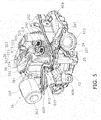
Fig. 1 is a cross sectional diagram of a portion of an engine. -
Fig. 2 is a diagram where a cylinder head and a head cover are viewed from a direction which is perpendicular to a cylinder axis and a cam axis. -
Fig. 3 is a cross sectional diagram where a cylinder head and a head cover are viewed from a direction which is perpendicular to a cylinder axis and a cam axis. -
Fig. 4 is a perspective diagram of an inner section of a cylinder head. -
Fig. 5 is a perspective diagram of an inner section of a cylinder head. -
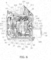
Fig. 6 is a diagram where an inner section of a cylinder head is viewed from a cylinder axial direction. -
Fig. 7 is a cross sectional diagram where an inner section of a cylinder head is viewed from a cam axial direction. -
Fig. 8 is a cross sectional diagram of the vicinity of a second support wall and a pressing member. -
Fig. 9 is a cross sectional diagram where an inner section of a cylinder head is viewed from a cam axial direction. -
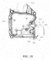
Fig. 10 is a diagram where a cylinder head and a head cover are viewed from a cylinder axial direction. -
Fig. 11 is a cross sectional diagram where a portion of an engine is viewed from a direction which is perpendicular to a cam axis and a cylinder axis. -
Fig. 12 is a cross sectional diagram where a portion of an engine is viewed from a direction which is perpendicular to a cam axis and a cylinder axis. - Below, an
engine 1 according to an embodiment will be described with reference to the diagrams. Theengine 1 according to the present embodiment is a water cooled single cylinder engine.Fig. 1 is a cross sectional diagram of a portion of theengine 1. As shown inFig. 1 , theengine 1 includes acrank shaft 2, a crankcase 3, and a cylinder section 4. The crankcase 3 accommodates thecrank shaft 2. The cylinder section 4 includes acylinder body 5, acylinder head 6, and ahead cover 7. Thecylinder body 5 is connected to the crankcase 3. Thecylinder body 5 may be integrated with thecrank case 3 or thecylinder body 5 and the crank case may be separate. Thecylinder body 5 accommodates apiston 8. Thepiston 8 is joined to the crankshaft 2 via a connectingrod 9. - Here, in the present embodiment, a direction from the
cylinder head 6 toward thehead cover 7 in a direction of a cylinder axis Ax1 of thecylinder body 5 is referred to as a "head cover side". A direction from thecylinder head 6 toward thecylinder body 5 in the direction of the cylinder axis Ax1 is referred to as a "cylinder body side". - The
cylinder head 6 is arranged on the head cover side of thecylinder body 5. Thecylinder head 6 is attached to thecylinder body 5. Thehead cover 7 is arranged on the head cover side of thecylinder head 6. Thehead cover 7 is attached to thecylinder head 6. The cylinder axis Ax1 is perpendicular with regard to a central axis Ax2 of the crank shaft 2 (referred to below as a "crank axis Ax2"). Thecylinder head 6 includes acombustion chamber 11. Aspark plug 12 is attached to thecylinder head 6. A front end section of thespark plug 12 is arranged to face thecombustion chamber 11. A base end section of thespark plug 12 is arranged at an outer section of theengine 1. Avalve gear 13 is accommodated in thecylinder head 6 and thehead cover 7. - The
valve gear 13 is a mechanism for opening and closingexhaust valves intake valves valve gear 13 adopts a SOHC (single overhead cam shaft) mechanism. Thevalve gear 13 adopts a so-called variable valve gear which switches the timing of the opening and closing of theintake valves valve gear 13 includes acam shaft 14. Thecam shaft 14 is supported by thecylinder head 6. A central axis Ax3 of the cam shaft 14 (referred to below as a "cam axis Ax3") is perpendicular with regard to the cylinder axis Ax1. The cam axis Ax3 is parallel to the crank axis Ax2. - The
cam shaft 14 includes a first camshaft end section 141 and a second camshaft end section 142. A first camshaft driving section 143 is provided at the first camshaft end section 141. The first camshaft driving section 143 is a sprocket. The first camshaft driving section 143 meshes with acam chain 15 and thecam chain 15 is joined to thecam shaft 14. A second camshaft driving section 201 is provided in thecrank shaft 2. The second camshaft driving section 201 is a sprocket. The second camshaft driving section 201 meshes with thecam chain 15 and thecam chain 15 is joined to the crankshaft 2. That is, thecam chain 15 is wound around the first camshaft driving section 143 of thecam shaft 14 and the second camshaft driving section 201 of thecrank shaft 2. Thecam shaft 14 is rotated by the rotation of thecrank shaft 2 being transmitted to thecam shaft 14 via thecam chain 15. - The
cam chain chamber 16 is provided in thecylinder head 6 and thecylinder body 5. Thecam chain 15 is arranged in thecam chain chamber 16. Thecam chain chamber 16 is arranged in a direction which is perpendicular to the cylinder axis Ax1 with regard to thecombustion chamber 11. That is, thecam chain chamber 16 is arranged to line up with thecombustion chamber 11 in the direction of the cam axis Ax3. - A
water pump 17 is joined to the first camshaft end section 141. Thewater pump 17 is arranged in the direction of the cam axis Ax3 of thecam shaft 14. Thewater pump 17 is connected to a cooling liquid path which is not shown in the diagrams and aradiator 19 in theengine 1 via a coolingliquid hose 18. Thewater pump 17 circulates a cooling liquid in theengine 1 due to being driven by the rotation of thecam shaft 14. -
Fig. 2 is a diagram where thecylinder head 6 and thehead cover 7 are viewed from a direction which is perpendicular to the cylinder axis Ax1 and the cam axis Ax3.Fig. 3 is a cross sectional diagram where thecylinder head 6 and thehead cover 7 are viewed from a direction which is perpendicular to the cylinder axis Ax1 and the cam axis Ax3. Here, thewater pump 17 is removed from thecylinder head 6 and thehead cover 7 inFig. 2 andFig. 3 . - The
cylinder head 6 includes afirst end section 601 and asecond end section 602. Thefirst end section 601 is arranged to face anend section 701 of thehead cover 7 in the direction of the cylinder axis Ax1. Thesecond end section 602 is arranged to face an end section of thecylinder body 5 in the direction of the cylinder axis Ax1. Thefirst end section 601 and thesecond end section 602 extend in a direction which is perpendicular with regard to the cylinder axis Ax1. - As shown in
Fig. 3 , a first virtual plane P1 which includes thefirst end section 601 of thecylinder head 6 and a second virtual plane P2 which includes theend section 701 of thehead cover 7 overlap with thecam shaft 14. In detail, the first virtual plane P1 and the second virtual plane P2 are positioned more to the head cover side than the cam axis Ax3. Here, agasket 21 is interposed between thefirst end section 601 of thecylinder head 6 and theend section 701 of thehead cover 7. - The
cylinder head 6 includes a firstcylinder side wall 603 and a secondcylinder side wall 604. The firstcylinder side wall 603 and the secondcylinder side wall 604 are arranged to face the direction of the cam axis Ax3. The secondcylinder side wall 604 is closer to thecam chain chamber 16 than the firstcylinder side wall 603. The secondcylinder side wall 604 is closer to the first camshaft driving section 143 than the firstcylinder side wall 603. - The
head cover 7 includes a firstcover side wall 702 and a secondcover side wall 703. The firstcover side wall 702 and the secondcover side wall 703 are arranged to face the direction of the cam axis Ax3. The firstcover side wall 702 is positioned on the head cover side of the firstcylinder side wall 603 and is connected to the firstcylinder side wall 603. The secondcover side wall 703 is positioned on the head cover side of the secondcylinder side wall 604 and is connected to the secondcylinder side wall 604. The secondcover side wall 703 is closer to thecam chain chamber 16 than the firstcover side wall 702. The secondcover side wall 703 is closer to the first camshaft driving section 143 than the firstcover side wall 702. -
Fig. 4 andFig. 5 are perspective diagrams of an inner section of thecylinder head 6.Fig. 6 is a diagram where an inner section of thecylinder head 6 is viewed from the direction of the cylinder axis Ax1. As shown inFig. 6 , the firstcylinder side wall 603 includes a first protrudingwall section 605, a second protrudingwall section 606, and aconcave section 607. The first protrudingwall section 605 and the second protrudingwall section 606 have a shape which protrudes to the outside of thecylinder head 6 in the direction of the cam axis Ax3. Theconcave section 607 is positioned between the first protrudingwall sections 605 and the second protrudingwall section 606. Theconcave section 607 has a shape which is depressed toward the inside of thecylinder head 6 in the direction of the cam axis Ax3. Thespark plug 12 described above is attached to the firstcylinder side wall 603. The base end section of thespark plug 12 is positioned in theconcave section 607 in the firstcylinder side wall 603. That is, the base end section of thespark plug 12 is positioned between the first protrudingwall section 605 and the second protrudingwall section 606 when viewed from the direction of the cylinder axis Ax1. - The
cylinder head 6 includes a thirdcylinder side wall 608 and a fourthcylinder side wall 609. The thirdcylinder side wall 608 and the fourthcylinder side wall 609 are arranged to line up in a direction which is perpendicular to the cam axis Ax3 and the cylinder axis Ax1. A connectingsection 610 of an exhaust pipe (which is not shown in the diagram) is provided in the thirdcylinder side wall 608. As shown inFig. 4 , a connectingsection 611 of an intake pipe (which is not shown in the diagram) is provided in the fourthcylinder side wall 609. - The
cylinder head 6 includes afirst support wall 612 and asecond support wall 613. Thefirst support wall 612 and thesecond support wall 613 are arranged to line up in the direction of the cam axis Ax3. Thefirst support wall 612 and thesecond support wall 613 support thecam shaft 14 such that thecam shaft 14 is able to rotate. As shown inFig. 3 , thefirst support wall 612 supports thecam shaft 14 via afirst bearing 22. Thesecond support wall 613 supports thecam shaft 14 via asecond bearing 23. Thefirst support wall 612 and thesecond support wall 613 are arranged between the first camshaft driving section 143 and the firstcylinder side wall 603. Thesecond support wall 613 is closer to the first camshaft driving section 143 than thefirst support wall 612. Thesecond support wall 613 is arranged between thefirst support wall 612 and the first camshaft driving section 143 in the direction of the cam axis Ax3. The top section of thefirst support wall 612 is positioned more to the head cover side than thefirst end section 601 of thecylinder head 6. The top section of thesecond support wall 613 is positioned more to the head cover side than thefirst end section 601 of thecylinder head 6. -
Fig. 7 is a cross sectional diagram where an inner section of thecylinder head 6 is viewed from the direction of the cam axis Ax3. As shown inFig. 4 to Fig. 7 , theintake valves exhaust valves cylinder head 6. As shown inFig. 7 , thecylinder head 6 includes anintake port 614 and anexhaust port 615 which are linked to thecombustion chamber 11. Theintake valves intake port 614. As shown inFig. 6 , theintake valves first intake valve 26 and asecond intake valve 27. Thefirst intake valve 26 and thesecond intake valve 27 are arranged to line up in the direction of the cam axis Ax3. As shown inFig. 7 , anintake valve spring 261 is attached to thefirst intake valve 26. Theintake valve spring 261 presses thefirst intake valve 26 in a direction so that thefirst intake valve 26 closes theintake port 614. In the same manner, an intake valve spring 271 (refer toFig. 4 ) is attached to thesecond intake valve 27 and thesecond intake valve 27 is pressed in a direction so that thesecond intake valve 27 closes theintake port 614. - The
exhaust valves exhaust port 615. As shown inFig. 6 , theexhaust valves first exhaust valve 24 and asecond exhaust valve 25. Thefirst exhaust valve 24 and thesecond exhaust valve 25 are arranged to line up in the direction of the cam axis Ax3. As shown inFig. 5 andFig. 7 , anexhaust valve spring 241 is attached to thefirst exhaust valve 24. Theexhaust valve spring 241 presses thefirst exhaust valve 24 in a direction so that thefirst exhaust valve 24 closes theexhaust port 615. Anexhaust valve spring 251 is attached to thesecond exhaust valve 25 and thesecond exhaust valve 25 is pressed in a direction so that thesecond exhaust valve 25 closes theexhaust port 615. - As shown in
Fig. 3 , thecam shaft 14 includes afirst intake cam 144, asecond intake cam 145, and anexhaust cam 146. Thefirst intake cam 144, thesecond intake cam 145, and theexhaust cam 146 are arranged to line up in the direction of the cam axis Ax3. Theexhaust cam 146 is the closest to the first camshaft driving section 143 out of thefirst intake cam 144, thesecond intake cam 145, and theexhaust cam 146. Thefirst intake cam 144 is the farthest from the first camshaft driving section 143 out of thefirst intake cam 144, thesecond intake cam 145, and theexhaust cam 146. Thesecond intake cam 145 is arranged between thefirst intake cam 144 and theexhaust cam 146 in the direction of the cam axis Ax3. - As shown in
Fig. 7 , thevalve gear 13 includes anexhaust rocker shaft 31 and anexhaust rocker arm 32. Theexhaust rocker shaft 31 is arranged to be parallel to thecam shaft 14. Theexhaust rocker shaft 31 is supported by thecylinder head 6. In detail, theexhaust rocker shaft 31 is supported by thefirst support wall 612 and thesecond support wall 613. The central axis of theexhaust rocker shaft 31 is positioned more to the head cover side than the cam axis Ax3. - The
exhaust rocker arm 32 is supported by theexhaust rocker shaft 31 so as to be able to swing centered on theexhaust rocker shaft 31. Theexhaust rocker arm 32 is provided so as to be able to operate theexhaust valves exhaust rocker arm 32 includes anarm body 321, aroller support section 322, aroller 323, and an exhaustvalve pressurizing section 324. - The
arm body 321 includes a throughhole 327 and theexhaust rocker shaft 31 passes through the throughhole 327. Theroller support section 322 protrudes from thearm body 321 to thecam shaft 14 side. Theroller support section 322 supports theroller 323 so as to be able to rotate. The rotation central axis of theroller 323 is parallel to the cam axis Ax3. Theroller 323 is positioned on thecam shaft 14 side of theexhaust rocker shaft 31. Theroller 323 comes into contact with theexhaust cam 146 and is rotated due to rotation of theexhaust cam shaft 146. - The exhaust
valve pressurizing section 324 protrudes from thearm body 321 to the opposite side to thecam shaft 14. That is, the exhaustvalve pressurizing section 324 protrudes from thearm body 321 to an end section of thefirst exhaust valve 24, that is, astem end 242 side (referred to below as "exhaust valve side"). As shown inFig. 5 andFig. 6 , afirst adjusting screw 325 and asecond adjusting screw 326 are provided at the tips of the exhaustvalve pressurizing section 324. The tip of the first adjustingscrew 325 opposes the stem end 242 of thefirst exhaust valve 24. The tip of thesecond adjusting screw 326 opposes an end section of thesecond exhaust valve 25, that is, astem end 252. - When the
roller 323 is pressed up by theexhaust cam 146, the exhaustvalve pressurizing section 324 presses thestem end 242 in thefirst exhaust valve 24 and thestem end 252 in thesecond exhaust valve 25 down due to theexhaust rocker arm 32 swinging. Due to this, theexhaust port 615 is opened by thefirst exhaust valve 24 and thesecond exhaust valve 25 being pressed down. When theroller 323 is not pressed up by theexhaust cam 146, theexhaust port 615 is closed by thefirst exhaust valve 24 and thesecond exhaust valve 25 being pressed up by the exhaust valve springs 241 and 251. - As shown in
Fig. 3 , thevalve gear 13 includes anintake rocker shaft 33, anintake rocker arm 34, aswitching pin member 35, and anactuator 39. Theintake rocker shaft 33 is arranged to be parallel to thecam shaft 14. Theintake rocker shaft 33 is supported by thecylinder head 6. In detail, theintake rocker shaft 33 is supported by thefirst support wall 612 and thesecond support wall 613. The central axis of theintake rocker shaft 33 is positioned more to the head cover side than the cam axis Ax3. - The
intake rocker arm 34 includes afirst rocker arm 36 and asecond rocker arm 37. Thefirst rocker arm 36 is supported by theintake rocker shaft 33 so as to be able to swing centered on theintake rocker shaft 33. Thefirst rocker arm 36 is provided as to be able to operate theintake valves first rocker arm 36 includes afirst arm body 361 shown inFig. 3 , a firstroller support section 362 shown inFig. 6 , afirst roller 363, an intakevalve pressurizing section 364, and afirst linking section 365. - As shown in
Fig. 3 , thefirst arm body 361 includes a through hole 356 and theintake rocker shaft 33 passes through the throughhole 366. The firstroller support section 362 protrudes from thefirst arm body 361 to thecam shaft 14 side. The firstroller support section 362 supports thefirst roller 363 so as to be able to rotate. The rotation central axis of thefirst roller 363 is parallel to the cam axis Ax3. Thefirst roller 363 is positioned on thecam shaft 14 side of theintake rocker shaft 33. Thefirst roller 363 comes into contact with thefirst intake cam 144 and is rotated due to rotation of thefirst intake cam 144. - The intake
valve pressurizing section 364 protrudes from thefirst arm body 361 to the opposite side to thecam shaft 14. That is, the intakevalve pressurizing section 364 protrudes from thefirst arm body 361 to astem end 262 side of the first intake valve 26 (referred to below as "intake valve side"). As shown inFig. 6 , afirst adjusting screw 367 and asecond adjusting screw 368 are provided at the tip of the intakevalve pressurizing section 364. The tip of the first adjustingscrew 367 opposes the stem end 262 of thefirst intake valve 26. The tip of thesecond adjusting screw 368 opposes astem end 272 of thesecond intake valve 27. - The
first linking section 365 is connected to the intakevalve pressurizing section 364. Thefirst linking section 365 is positioned more to the head cover side than theintake rocker shaft 33. Thefirst linking section 365 is positioned more to the intake valve side than theintake rocker shaft 33. Thefirst linking section 365 is positioned more to the head cover side than the intakevalve pressurizing section 364. As shown inFig. 3 , thefirst linking section 365 includes a throughhole 369. The throughhole 369 extends in the direction of the cam axis Ax3. The switchingpin member 35 is inserted into the throughhole 369. - As shown in
Fig. 7 , thesecond rocker arm 37 is supported so as to be able to rotate centered on theintake rocker shaft 33. Thesecond rocker arm 37 is arranged to line up with thefirst rocker arm 36 in the direction of the cam axis Ax3. Thesecond rocker arm 37 is arranged at thecam chain chamber 16 side of thefirst rocker arm 36. That is, thesecond rocker arm 37 is closer to the first camshaft driving section 143 than thefirst rocker arm 36. Thesecond rocker arm 37 includes asecond arm body 371, a secondroller support section 372, asecond roller 373, and asecond linking section 374. - The
second arm body 371 includes a throughhole 375 and theintake rocker shaft 33 passes through the throughhole 375. The secondroller support section 372 protrudes from thesecond arm body 371 to thecam shaft 14 side. The secondroller support section 372 supports thesecond roller 373 so as to be able to rotate. The rotation central axis of thesecond roller 373 is parallel to the cam axis Ax3. Thesecond roller 373 is positioned on thecam shaft 14 side of theintake rocker shaft 33. Thesecond roller 373 comes into contact with thesecond intake cam 145 and is rotated due to rotation of thesecond intake cam 145. - The
second linking section 374 protrudes from thesecond arm body 371 to the opposite side to thecam shaft 14. That is, thesecond linking section 374 protrudes from thesecond arm body 371 to the intake valve side. Thesecond linking section 374 is positioned more to the head cover side than theintake rocker shaft 33. Thesecond linking section 374 is positioned more to the head cover side than the intakevalve pressurizing section 364. As shown inFig. 3 , thesecond linking section 374 includes a throughhole 376. The throughhole 376 extends in the direction of the cam axis Ax3. The throughhole 376 of thesecond linking section 374 is arranged to line up with the throughhole 369 of thefirst linking section 365 in the direction of the cam axis Ax3. Accordingly, it is possible for theswitching pin member 35 to be inserted into the throughhole 376 of thesecond linking section 374. - The
valve gear 13 includes a pressingmember 38 shown inFig. 6 . The pressingmember 38 presses thesecond rocker arm 37 in a direction where thesecond roller 373 applies pressure to thecam shaft 14. In the present embodiment, the pressingmember 38 is a coil spring and theintake rocker shaft 33 runs through the pressingmember 38. Thesecond rocker arm 37 includes afirst support member 41. Thefirst support member 41 supports one end of the pressingmember 38. Thefirst support member 41 has the shape of a pin and protrudes from thesecond rocker arm 37 in the direction of the cam axis Ax3.Fig. 8 is a cross sectional diagram of the vicinity of thesecond support wall 613 and the pressingmember 38. - As shown in
Fig. 8 , thevalve gear 13 includes asecond support member 42. Thesecond support member 42 supports the other end of the pressingmember 38. Thesecond support member 42 is configured by a member which is bent and has a cross sectional shape with an L shape. Astep section 619 is provided in thesecond support wall 613 and thesecond support member 42 is supported in thestep section 619. - As shown in
Fig. 3 , the switchingpin member 35 is able to be moved in the axial direction of thecam shaft 14 and is provided to be able to be moved between a first position and a second position. The switchingpin member 35 is arranged to span between the throughhole 369 of thefirst linking section 365 and the throughhole 376 of thesecond linking section 374 at the first position. Due to this, the switchingpin member 35 links thefirst rocker arm 36 and thesecond rocker arm 37 at the first position and thefirst rocker arm 36 and thesecond rocker arm 37 swing in an integrated manner. In this state, the switchingpin member 35 swings together with thefirst rocker arm 36 and thesecond rocker arm 37. - The switching
pin member 35 is arranged at the throughhole 369 of thefirst linking section 365 and is not arranged at the throughhole 376 of thesecond linking member 374 at the second position. Due to this, the switchingpin member 35 does not link thefirst rocker arm 36 and thesecond rocker arm 37 at the second position and thefirst rocker arm 36 and thesecond rocker arm 37 swing independently from each other. In this state, the switchingpin member 35 swings together with thefirst rocker arm 36. - An
elastic member 44 is provided in thefirst linking section 365. Theelastic member 44 is arranged in the throughhole 369 of thefirst linking section 365. Theelastic member 44 presses theswitching pin member 35 in a direction from the first position toward the second position. Accordingly, when theswitching pin member 35 is not pressurized by theactuator 39, the switchingpin member 35 is held at the second position by theelastic member 44. When theswitching pin member 35 is pressurized by theactuator 39, the switchingpin member 35 moves from the second position to the first position against the pressing force of theelastic member 44. - As shown in
Fig. 7 , the switchingpin member 35 is positioned more to the head cover side than thefirst end section 601 of thecylinder head 6 and theend section 701 of thehead cover 7. Accordingly, the switchingpin member 35 overlaps with thehead cover 7 when viewed from the axial direction of thecam shaft 14. As shown inFig. 7 , the switchingpin member 35 is positioned on the intake valve side of theintake rocker shaft 33. That is, the switchingpin member 35 is positioned between theintake rocker shaft 33 and the stem end 262 of thefirst intake valve 26 in a direction which is perpendicular to the cylinder axis Ax1 and the axis of thecam shaft 14. The distance between the shaft center of theintake rocker shaft 33 and the shaft center of theswitching pin member 35 is shorter than the distance between the shaft center of theintake rocker shaft 33 and the stem end 262 of thefirst intake valve 26 when viewed from the axial direction of thecam shaft 14. In addition, theintake rocker shaft 33 is positioned between the switchingpin member 35 and thefirst roller 363 in a direction which is perpendicular to the cylinder axis Ax1 and the axis of thecam shaft 14. In the same manner, theintake rocker shaft 33 is positioned between the switchingpin member 35 and thesecond roller 372 in a direction which is perpendicular to the cylinder axis Ax1 and the axis of thecam shaft 14. -
Fig. 9 illustrates a state where thefirst rocker arm 36 and thesecond rocker arm 37 swing using dashed lines. When theswitching pin member 35 is positioned at the first position, thefirst rocker arm 36 is linked to thesecond rocker arm 37 and swings with thesecond rocker arm 367 in an integrated manner. As a result, when thesecond roller 373 is pressed up by thesecond intake cam 145, due to thesecond rocker arm 37 swinging centered on theintake rocker shaft 33, thefirst rocker arm 35 also swings in a direction which lowers the intakevalve pressurizing section 364. Due to this, the tip of the first adjustingscrew 367 presses down the stem end 262 of thefirst intake valve 26 and the tip of thesecond adjusting screw 368 presses down the stem end 272 of thesecond intake valve 27. Due to this, thefirst intake valve 26 and thesecond intake valve 27 open theintake port 614. When thesecond roller 373 is not pressed up by thesecond intake cam 145, theintake port 614 is closed off by thefirst intake valve 26 and thesecond intake valve 27 being pressed up by the intake valve springs 261 and 271. - When the
switching pin member 35 is positioned at the second position, thefirst rocker arm 36 swings independently of thesecond rocker arm 37. As a result, when thefirst roller 363 is pressed up by thefirst intake cam 144, thefirst rocker arm 36 swings centered on theintake rocker shaft 33 in a direction where the intakevalve pressurizing section 364 is lowered, Due to this, the tip of the first adjustingscrew 367 presses down the stem end 262 of thefirst intake valve 26 and the tip of thesecond adjusting screw 368 presses down the stem end 272 of thesecond intake valve 27. Due to this, thefirst intake valve 26 and thesecond intake valve 27 open theintake port 614. When thefirst roller 363 is not pressed up by thefirst intake cam 144, theintake port 614 is closed off by thefirst intake valve 26 and thesecond intake valve 27 being pressed up by the intake valve springs 261 and 271. - Here, the shapes of the
first intake cam 144 and thesecond intake cam 145 are set so that thesecond intake cam 145 presses up thesecond roller 373 before the tip of thefirst intake cam 144 reaches thefirst roller 363. As a result, when theswitching pin member 35 is positioned at the first position, the rotation of thefirst intake cam 144 is not transmitted to thefirst rocker arm 36 due to the operation of thefirst rocker arm 36 by rotating of thesecond intake cam 145. Accordingly, when theswitching pin member 35 is positioned at the first position, the opening and closing operation of thefirst intake valve 26 and thesecond intake valve 27 are performed according to the rotation of thesecond intake cam 145. On the other hand, when theswitching pin member 35 is positioned at the second position, the rotation of thesecond intake cam 145 is not transmitted to thefirst rocker arm 36. As a result, when theswitching pin member 35 is positioned at the second position, the opening and closing operation of thefirst intake valve 26 and thesecond intake valve 27 is performed according to the rotation of thefirst intake cam 144. - The
actuator 39 is an electromagnetic solenoid and switches the position of theswitching pin member 35 from the second position to the first position by pressurizing theswitching pin member 35 in the axial direction of thecam shaft 14 due to the flow of electricity, When the flow of electricity to theactuator 39 stops, the position of theswitching pin member 35 is returned from the first position to the second position due to the elasticity of theelastic member 44. - As shown in
Fig. 6 , theactuator 39 overlaps with thefirst end section 601 of thecylinder head 6 when viewed from the direction of the cylinder axis Ax1. That is, a portion of theactuator 39 is positioned more to the inner side of thecylinder head 6 than thefirst end section 601 of thecylinder head 6. Theactuator 39 is arranged at the opposite side to thecam chain chamber 16 with regard to thecam shaft 14 when viewed from the direction of the cylinder axis Ax1. An extended line of the cam axis Ax3 is positioned between the connectingsection 610 of the exhaust pipe and theactuator 39 when viewed from the direction of the cylinder axis Ax1. As shown inFig. 3 , theactuator 39 is positioned more to the head cover side than thefirst end section 601 of thecylinder head 6. - The
actuator 39 includes arod 391 which pressurizes the switchingpin member 35 and abody section 392 which drives therod 391. The central axis of therod 391 is parallel to the cam axis Ax3, Therod 391 is arranged so as to overlap with the switchingpin member 35 in the swinging range of theswitching pin member 35 when viewed from the direction of the cam axis Ax3. Therod 391 pressurizes the switchingpin member 35 by being driven by thebody section 392. Therod 391 is arranged to be close to thefirst support wall 612 described above. As shown inFig. 4 , thefirst support wall 612 includes aconcave section 620 which opposes the side surface of therod 391. Theconcave section 620 has a shape which is depressed so as to avoid therod 391. - The
actuator 39 is attached to thehead cover 7. In detail, thebody section 392 is attached to thehead cover 7. Therod 391 is supported by thehead cover 7. As shown inFig. 3 , a throughhole 704 is provided in thehead cover 7 and therod 391 runs through the throughhole 704. As shown inFig. 6 , theactuator 39 is positioned more to theintake valves spark plug 12 when viewed from the direction of the cylinder axis Ax1. Thespark plug 12 is arranged to line up with thecam shaft 14 in the direction of the cam axis Ax3 when viewed from the direction of the cylinder axis Ax1. -
Fig. 10 is a diagram where thecylinder head 6 and thehead cover 7 are viewed from the direction of the cylinder axis Ax1. As shown inFig. 2 andFig. 10 , theactuator 39 is attached to thehead cover 7 at the outside of theengine 1. Theactuator 39 is attached to the firstcover side wall 702. Theactuator 39 is arranged so as to not overlap with an extended line of the axis of thespark plug 12. Afirst boss section 705 and asecond boss section 706 are provided in the firstcover side wall 702. Thefirst boss section 705 and thesecond boss section 706 protrude from the firstcover side wall 702 toward the outside of thecylinder head 6 in the direction of the cam axis Ax3. Thefirst boss section 705 and thesecond boss section 706 are arranged to line up in a direction which is perpendicular to the cam axis Ax3 and the cylinder axis Ax1. Theactuator 39 includes aflange section 393 which protrudes from thebody section 392. Theflange section 393 is fixed to thefirst boss section 705 and thesecond boss section 706 usingbolts actuator 39 is fixed to the firstcover side wall 702. -
Fig. 11 is a cross sectional diagram of a portion of theengine 1 which is viewed from a direction which is perpendicular to the cam axis Ax3 and the cylinder axis Ax1. As shown inFig. 11 , thecylinder head 6, thecylinder body 5, and the crankcase 3 are fastened by afirst fastening bolt 61 and asecond fastening bolt 62. Thecylinder head 6, thecylinder body 5, and the crankcase 3 are fastened by a third fastening bolt and a fourth fastening bolt which are not shown in the diagram. Thefirst fastening bolt 61 includes afirst head section 65. Thesecond fastening bolt 62 includes asecond head section 66. The third fastening bolt includes athird head section 67 which is shown inFig. 6 . The fourth fastening bolt includes afourth head section 68 which is shown inFig. 6 . The first to thefourth head sections 65 to 68 fix thecylinder head 6. Thefirst head section 65 is configured by a shaft section of thefirst fastening bolt 61 and a nut which is separate but may be integral with the shaft section of thefirst fastening bolt 61. The second to thefourth head sections 66 to 68 are the same as thefirst head section 65. - The
first head section 65 and thesecond head section 66 are arranged to line up in the direction of the cam axis Ax3. Thethird head section 67 and thefourth head section 68 are arranged to line up in the direction of the cam axis Ax3. Thefirst head section 65 and thethird head section 67 are arranged to line up in a direction which is perpendicular to the cam axis Ax3 and the cylinder axis Ax1. Thesecond head section 66 and thefourth head section 68 are arranged to line up in a direction which is perpendicular to the cam axis Ax3 and the cylinder axis Ax1. - The
first head section 65 is arranged between the firstcylinder side wall 603 and thesecond head section 66 in the direction of the cam axis Ax3. The firstcylinder side wall 603 is closer to thefirst head section 65 than the secondcylinder side wall 604. Thefirst head section 65 is arranged in the first protrudingwall section 605 of the firstcylinder side wall 603. Thefirst head section 65 overlaps with theactuator 39 when viewed from the direction of the cylinder axis Ax1 of thecylinder body 5. The axis of theswitching pin member 35 is positioned on theintake rocker shaft 33 side with regard to the center of thefirst head section 65 in a direction which is perpendicular to the cam axis Ax3 and the cylinder axis Ax1. The axis of theswitching pin member 35 is positioned between the center of thefirst head section 65 and theintake rocker shaft 33 in a direction which is perpendicular to the cam axis Ax3 and the cylinder axis Ax1. - The
second head section 66 is arranged between the secondcylinder side wall 604 and thefirst head section 65 in the direction of the cam axis Ax3. The secondcylinder side wall 604 is closer to thesecond head section 66 than the firstcylinder side wall 603. The camshaft driving section 143 is arranged between the secondcylinder side wall 604 and thesecond head section 66 in the direction of the cam axis Ax3. Thesecond head section 66 is arranged on thesecond support wall 613. Thefirst head section 65 and thesecond head section 66 are arranged on the intake valve side with regard to the cam axis Ax3. The distance between the firstcylinder side wall 603 and thefirst head section 65 in the direction of the cam axis Ax3 is shorter than the distance between the secondcylinder side wall 604 and thesecond head section 66 in the direction of the cam axis Ax3. - The
third head section 67 is arranged between the firstcylinder side wall 603 and thefourth head section 68 in the direction of the axis Ax3, The firstcylinder side wall 603 is closer to thethird head section 67 than the secondcylinder side wall 604. Thethird head section 67 is arranged in the second protrudingwall section 606 of the firstcylinder side wall 603. - The
fourth head section 68 is arranged between the secondcylinder side wall 604 and thethird head section 67 in the direction of the cam axis Ax3. The secondcylinder side wall 604 is closer to thefourth head section 68 than the firstcylinder side wall 603. The camshaft driving section 143 is arranged between the secondcylinder side wall 604 and thefourth head section 68 in the direction of the cam axis Ax3. Thefourth head section 68 is arranged on thesecond support wall 613. Thethird head section 67 and thefourth head section 68 are arranged on the exhaust valve side with regard to the cam axis Ax3. The distance between the firstcylinder side wall 603 and thethird head section 67 in the direction of the cam axis Ax3 is shorter than the distance between the secondcylinder side wall 604 andfourth head section 68 in the direction of the cam axis Ax3. - As shown in
Fig. 11 , the inner surface of the firstcover side wall 702 and the inner surface of the secondcover side wall 703 are inclined so that between the firstcover side wall 702 and secondcover side wall 703 becomes narrower toward the head cover side. - The
cylinder head 6 includes a first throughhole 621 where thefirst fastening bolt 61 is arranged and a second throughhole 622 through which thesecond fastening bolt 62 is arranged. The first throughhole 621 and the second throughhole 622 extend in the direction of the cylinder axis Ax1. The second throughhole 622 is provided to pass through thesecond support wall 613. As shown inFig. 12 , a distance D1 to thefirst head section 65 in a direction of the cylinder axis Ax1 from the third virtual plane P3 which includes the crank axis Ax2 and is perpendicular to the cylinder axis Ax1 of thecylinder body 5 is shorter than a distance D2 to thesecond head section 66 in a direction of the cylinder axis Ax1 from the third virtual plane P3. That is, thefirst head section 65 is positioned more to the cylinder body side than thesecond head section 66. - The
first fastening bolt 61 does not overlap with thehead cover 7 when viewed from the direction of the cam axis Ax3. That is, thefirst head section 65 is positioned more to the cylinder body side than thefirst end section 601 of thecylinder head 6. Thesecond fastening bolt 62 overlaps with thehead cover 7 when viewed from the direction of the cam axis Ax3. That is, thesecond head section 66 is positioned more to the head cover side than thefirst end section 601 of thecylinder head 6. - Although omitted in the diagram, the
third head section 67 is positioned at the same height as thefirst head section 65 and thefourth head section 68 is positioned at the same height as thesecond head section 66. Accordingly, thethird head section 67 is positioned more to the cylinder body side than thefourth head section 68. - In an engine where the switching pin member is positioned more to the opposite side of the end section of the valve than the rocker shaft when viewed from the axial direction of the cam shaft as in engines according to techniques in the background art, when the rocker arms rotate around the rocker shaft in a direction in which the end section of the valve is pressed down, the switching pin member is moved upward which is the opposite direction. As a result, it is necessary to secure a large clearance between the cylinder head, which is positioned above the switching pin member, and the switching pin member. In this case, the size of the engine increases. In contrast to this, the switching
pin member 35 is moved to the cylinder body side when theintake valves engine 1 according to the present embodiment. As a result, it is possible to reduce the clearance on the head cover side of theswitching pin member 35 compared to a case where theswitching pin member 35 is moved to the head cover side when theintake valves valve gear 13 and it is possible to reduce the size of theengine 1. - The distance between the shaft center of the
intake rocker shaft 33 and the shaft center of theswitching pin member 35 is shorter than the distance between the shaft center of theintake rocker shaft 33 and the stem end 262 of thefirst intake valve 26. In this case, since the distance between theintake rocker shaft 33 and theswitching pin member 35 is short, the movement distance of theswitching pin member 35 when swinging is short. As a result, it is possible to reduce the diameter of therod 391. When the diameter of therod 391 is reduced, it is possible to reduce the size of thebody section 392 since the drive force for moving therod 391 is smaller, and it is possible to reduce the size of theengine 1. - Since the
first rocker arm 36 has thefirst roller 363, it is possible to reduce friction loss between thecam shaft 14 and thefirst rocker arm 36. Due to this, it is possible to improve fuel efficiency of theengine 1. In addition, the weight of thefirst rocker arm 36 on thecam shaft 14 side is heavier due to the weight of thefirst roller 363, but force for pressing down theintake valves switching pin member 35. Due to this, it is possible to improve fuel efficiency of theengine 1. - The
first roller 363 is positioned on thecam shaft 14 side with regard to theintake rocker shaft 33 when viewed from the direction of the cam axis Ax3. Accordingly, thefirst roller 363 and theswitching pin member 35 are arranged to be opposite to each other with regard to theintake rocker shaft 33 when viewed from the direction of the cam axis Ax3. In an engine where the switching pin member is positioned more to the opposite side of the end section of the valve than the rocker shaft when viewed from the axial direction of the cam shaft as in engines according to techniques in the background art, the roller which comes into contact with the cam of the cam shaft is arranged below the switching pin member. As a result, it is not easy for the position of the switching pin member to be lowered downward since the clearance between the cylinder head cover, which is positioned above the switching pin member, and the switching pin member is small. Furthermore, if the switching pin member is arranged between the rocker shaft and the roller by the distance between the rocker shaft and the roller being increased, it is possible to lower the position of the switching pin member downward while avoiding interference with the roller. However, in this case, the rocker arm is lengthened and the size of the variable valve gear is increased. As a result, the size of the engine increases. In contrast to this, since thefirst roller 363 and theswitching pin member 35 are arranged to be opposite to each other with regard to theintake rocker shaft 33, it is possible to arrange theswitching pin member 35 at a position which is close to theintake rocker shaft 33 while avoiding interference with thefirst roller 363 in theengine 1 according to the present embodiment. Due to this, it is possible to reduce the diameter of therod 391 and it is possible to reduce the size of theengine 1. - The
second roller 373 is positioned on the cam shalt 14 side with regard to theintake rocker shaft 33 when viewed from the direction of the cam axis Ax3. Accordingly, thesecond roller 373 and theswitching pin member 35 are arranged to be opposite to each other with regard to theintake rocker shaft 33. In an engine where the switching pin member is positioned more to the opposite side of the end section of the valve than the rocker shaft when viewed from the axial direction of the cam shaft as in engines according to techniques in the background art, the roller which comes into contact with the cam of the cam shaft is arranged below the switching pin member. As a result, it is not easy for the position of the switching pin member to be lowered downward since the clearance between the cylinder head cover, which is positioned above the switching pin member, and the switching pin member is small. Furthermore, if the switching pin member is arranged between the rocker shaft and the roller by the distance between the rocker shaft and the roller being increased, it is possible to lower the position of the switching pin member downward while avoiding interference with the roller. However, in this case, the rocker arm is lengthened and the size of the variable valve gear is increased. As a result, the size of the engine increases. In contrast to this, since thesecond roller 373 and theswitching pin member 35 are arranged to be opposite to each other with regard to theintake rocker shaft 33, it is possible to arrange theswitching pin member 35 at a position which is close to theintake rocker shaft 33 while avoiding interference with thesecond roller 373 in theengine 1 according to the present embodiment. Due to this, it is possible to reduce the diameter of therod 391 and it is possible to reduce the size of theengine 1. - The axis of the
switching pin member 35 is positioned on theintake rocker shaft 33 side with regard to the center of thefirst head section 65. Accordingly, it is possible to shorten thefirst rocker arm 36 and thesecond rocker arm 37 since the switchingpin member 35 is close to theintake rocker shaft 33. Due to this, it is possible to reduce the size of thevalve gear 13 and it is possible to reduce the size of theengine 1. - The
actuator 39 is attached to the firstcylinder side wall 603 and does not overlap with the extended line of the axis of thespark plug 12. Accordingly, it is possible to suppress theactuator 39 interfering with the moving in and out of thespark plug 12 even when theactuator 39 is arranged to be close to thespark plug 12. In addition, it is possible to further reduce the size of theengine 1 by arranging theactuator 39 to be close to thespark plug 12. - Above, an embodiment of the present invention has been described, but the present invention is not limited to the embodiment described above and various modifications are possible in a scope which does not depart from the scope of the invention.
- The
engine 1 is not limited to a water cooled single cylinder engine. For example, theengine 1 may be an air cooled engine. - The number of exhaust valves is not limited to two and may be one or three or more. The number of intake valves is not limited to two and may be one or three or more.
- The positions of the
first head section 65, thesecond head section 66, thethird head section 67, and thefourth head section 68 are not limited to the positions in the embodiment described above and may be modified. For example, in the embodiment described above, thefirst head section 65 does not overlap with thehead cover 7 in the direction of thecam shaft 14, but thefirst head section 65 may overlap with thehead cover 7 in the direction of thecam shaft 14. That is, thefirst head section 65 may be arranged more to the head cover side than theend section 701 of thehead cover 7. - The first virtual plane P1 which includes the
first end section 601 of thecylinder head 6 and the second virtual plane P2 which includes theend section 701 of thehead cover 7 may be arranged at the same height as the cam axis Ax3 or more to the cylinder body side than the cam axis Ax3. Alternatively, the first virtual plane P1 and the second virtual plane P2 may not overlap with thecam shaft 14. - The configuration and arrangement of the
valve gear 13 are not limited to the embodiment described above and may be modified- For example, theactuator 39 may be attached to thecylinder head 6. Alternatively, theactuator 39 may be arranged beside thecylinder head 6. Alternatively, theactuator 39 may be arranged so as to not overlap with theend section 701 of thehead cover 7 when viewed from the direction of the cylinder axis Ax1. Alternatively, theactuator 39 may be arranged so as to not overlap with thefirst head section 65 when viewed from the direction of the cylinder axis Ax1. Without being limited to a portion of theactuator 39, all of theactuator 39 may be positioned more to the inner side than thefirst end section 601 of thecylinder head 6. - The distance between the
intake rocker shaft 33 and theswitching pin member 35 may be equal to or more than the distance between theintake rocker shaft 33 and the stem end 262 of thefirst intake valve 26. The axis of theswitching pin member 35 may be positioned on the opposite side to theintake rocker shaft 33 with regard to the center of thefirst head section 65. Theactuator 39 may overlap with an extended line of the axis of thespark plug 12. - In the embodiment described above, the mechanism which switches the timing of the opening and closing of the valves using the actuator is adopted in the intake valves but may be adopted in the exhaust valves. That is, a mechanism which is the same as the mechanism which includes the
first rocker arm 36, thesecond rocker arm 37, the switchingpin member 35, and theactuator 39 described above may be provided in order to open and close the exhaust valves.
Claims (9)
- An engine (1) which is a single cylinder engine comprising:a cylinder section (4) including a combustion chamber (11);a valve (24 - 27) supported by the cylinder section (4), the valve (24 - 27) being configured to open and close an exhaust port (615) or an intake port (614) in the combustion chamber (11);a cam shaft (14) including an intake cam (144, 145) and an exhaust cam (146), the cam shaft (14) being supported by the cylinder section (4);a rocker shaft (33) supported by the cylinder section (4), the rocker shaft (33) being parallel to the cam shaft (14);a first rocker arm (36) supported by the rocker shaft (33), the first rocker arm (36) including one end section configured to be able to make contact with the cam shaft (14) and the other end section configured to be able to make contact with the valve (24 - 27), the first rocker arm (36) being configured to be operated in a direction in which the value (24 - 27) is pressed down;a second rocker arm (37) supported by the rocker shaft (33), the second rocker arm (37) including one end section configured to be able to make contact with the cam shaft (14), the second rocker arm (37) being arranged to line up with the first rocker arm (36) in an axial direction of the cam shaft (14);a switching pin member (35) configured to be moved in the axial direction of the cam shaft (14), the switching pin member (35) being configured to be moved between a first position at which the first rocker arm (36) and the second rocker arm (37) are linked and a second position at which the first rocker arm (36) and the second rocker arm (37) are not linked, the switching pin member (35) being configured to swing together with the first rocker arm (36) and the second rocker arm (37) at the first position; andan actuator (39) configured to switch the position of the switching pin member (35) between the first position and the second position by pressurizing the switching pin member (35) in the axial direction of the cam shaft (14),wherein the switching pin member (35) is positioned on an end section side of the valve (24 - 27) with regard to the rocker shaft (33) when viewed from the axial direction of the cam shaft (14).
- The engine (1) according to Claim 1, wherein the actuator (39) includes a rod (391) for pressurizing the switching pin member (35) and a body section (392) for driving the rod (391).
- The engine (1) according to Claim 1 or 2, wherein a distance between the rocker shaft (33) and the switching pin member (35) is shorter than a distance between the rocker shaft (33) and the end section of the valve (24 - 27).
- The engine (1) according to any of Claims 1 to 3, wherein the first rocker arm (36) includes a first roller (362) configured to come into contact with the intake cam (144, 145) or the exhaust cam (146), and the first roller (362) is positioned on the cam shaft side with regard to the rocker shaft (33) when viewed from the axial direction of the cam shaft (14).
- The engine (1) according to any of Claims 1 to 4, wherein the second rocker arm (37) includes a second roller (373) configured to come into contact with the intake cam (144, 145) or the exhaust cam (146), and the second roller (373) is positioned on the cam shaft side with regard to the rocker shaft (33) when viewed from the axial direction of the cam shaft (14).
- The engine (1) according to any of Claims 1 to 5, further comprising a fastening bolt (61, 62) arranged on the valve side with regard to an axis (Ax3) of the cam shaft (14).
- The engine (1) according to Claim 6, wherein an axis of the switching pin member (35) is positioned on the rocker shaft side with regard to a centre of a head section (65, 66) of the fastening bolt (61, 62).
- The engine (1) according to any of Claims 1 to 7, further comprising a spark plug (12) attached to a side section of the cylinder section (4) in the axial direction of the cam shaft (14), the spark plug (12) being supported by the cylinder section (4).
- The engine (1) according to Claim 8, wherein the actuator (39) is attached to the side section of the cylinder section (4) and does not overlap with an extended line of an axis of the spark plug (12).
Applications Claiming Priority (1)
| Application Number | Priority Date | Filing Date | Title |
|---|---|---|---|
| JP2013136583A JP2015010554A (en) | 2013-06-28 | 2013-06-28 | Engine |
Publications (3)
| Publication Number | Publication Date |
|---|---|
| EP2821601A2 true EP2821601A2 (en) | 2015-01-07 |
| EP2821601A3 EP2821601A3 (en) | 2015-12-30 |
| EP2821601B1 EP2821601B1 (en) | 2017-05-03 |
Family
ID=49510037
Family Applications (1)
| Application Number | Title | Priority Date | Filing Date |
|---|---|---|---|
| EP13191020.0A Active EP2821601B1 (en) | 2013-06-28 | 2013-10-31 | Engine |
Country Status (7)
| Country | Link |
|---|---|
| EP (1) | EP2821601B1 (en) |
| JP (1) | JP2015010554A (en) |
| CN (1) | CN104251146B (en) |
| CO (1) | CO7250119A1 (en) |
| ES (1) | ES2626379T3 (en) |
| PH (1) | PH12013000316B1 (en) |
| TW (1) | TWI582302B (en) |
Cited By (1)
| Publication number | Priority date | Publication date | Assignee | Title |
|---|---|---|---|---|
| EP2853700A1 (en) * | 2013-09-30 | 2015-04-01 | Honda Motor Co., Ltd. | Variable valve gear of internal combustion engine for saddle-ride type vehicle |
Families Citing this family (3)
| Publication number | Priority date | Publication date | Assignee | Title |
|---|---|---|---|---|
| JP6069765B2 (en) * | 2013-09-30 | 2017-02-01 | 本田技研工業株式会社 | Variable valve operating system for internal combustion engine for saddle riding type vehicle |
| JP2018197498A (en) | 2015-10-15 | 2018-12-13 | ヤマハ発動機株式会社 | Engine for saddle-type vehicle |
| JP6258383B2 (en) * | 2015-11-30 | 2018-01-10 | モートニック コーポレイション | Variable valve lift device for engine |
Citations (1)
| Publication number | Priority date | Publication date | Assignee | Title |
|---|---|---|---|---|
| JP2012077741A (en) | 2010-09-07 | 2012-04-19 | Honda Motor Co Ltd | Variable valve system of internal combustion engine |
Family Cites Families (8)
| Publication number | Priority date | Publication date | Assignee | Title |
|---|---|---|---|---|
| JPH07103812B2 (en) * | 1991-09-18 | 1995-11-08 | 本田技研工業株式会社 | Valve operating system with a function of changing the valve operating characteristics of an internal combustion engine |
| DE4227567C1 (en) * | 1992-08-20 | 1993-11-11 | Daimler Benz Ag | Valve drive system for a multi-cylinder internal combustion engine |
| DE4404683C1 (en) * | 1994-02-15 | 1995-03-02 | Daimler Benz Ag | Method for minimising the clearance in a valve gear |
| JPH07301108A (en) * | 1995-04-24 | 1995-11-14 | Mazda Motor Corp | Valve system for engine |
| JP2003027975A (en) * | 2001-07-12 | 2003-01-29 | Honda Motor Co Ltd | Outboard motor with internal combustion engine |
| EP2472075B1 (en) * | 2009-08-24 | 2014-09-17 | Yamaha Hatsudoki Kabushiki Kaisha | Variable valve device, engine with same, and saddled vehicle |
| JP5455838B2 (en) * | 2010-08-11 | 2014-03-26 | 本田技研工業株式会社 | Variable valve mechanism |
| JP2014047623A (en) * | 2012-08-29 | 2014-03-17 | Honda Motor Co Ltd | Variable valve device |
-
2013
- 2013-06-28 JP JP2013136583A patent/JP2015010554A/en not_active Withdrawn
- 2013-10-16 TW TW102137372A patent/TWI582302B/en active
- 2013-10-21 PH PH12013000316A patent/PH12013000316B1/en unknown
- 2013-10-29 CO CO13256720A patent/CO7250119A1/en unknown
- 2013-10-31 EP EP13191020.0A patent/EP2821601B1/en active Active
- 2013-10-31 CN CN201310529202.0A patent/CN104251146B/en active Active
- 2013-10-31 ES ES13191020.0T patent/ES2626379T3/en active Active
Patent Citations (1)
| Publication number | Priority date | Publication date | Assignee | Title |
|---|---|---|---|---|
| JP2012077741A (en) | 2010-09-07 | 2012-04-19 | Honda Motor Co Ltd | Variable valve system of internal combustion engine |
Cited By (1)
| Publication number | Priority date | Publication date | Assignee | Title |
|---|---|---|---|---|
| EP2853700A1 (en) * | 2013-09-30 | 2015-04-01 | Honda Motor Co., Ltd. | Variable valve gear of internal combustion engine for saddle-ride type vehicle |
Also Published As
| Publication number | Publication date |
|---|---|
| CN104251146B (en) | 2017-04-12 |
| CO7250119A1 (en) | 2015-04-30 |
| PH12013000316A1 (en) | 2015-04-27 |
| TWI582302B (en) | 2017-05-11 |
| PH12013000316B1 (en) | 2015-04-27 |
| TW201500637A (en) | 2015-01-01 |
| CN104251146A (en) | 2014-12-31 |
| EP2821601B1 (en) | 2017-05-03 |
| JP2015010554A (en) | 2015-01-19 |
| ES2626379T3 (en) | 2017-07-24 |
| BR102013027997A2 (en) | 2015-10-13 |
| EP2821601A3 (en) | 2015-12-30 |
Similar Documents
| Publication | Publication Date | Title |
|---|---|---|
| EP2821601B1 (en) | Engine | |
| EP2821602B1 (en) | Engine | |
| US8136501B2 (en) | Variable stroke engine | |
| EP2860381B1 (en) | Engine | |
| US8534243B2 (en) | Internal combustion engine with masking wall the curtain area of the intake valves | |
| JP5189520B2 (en) | High pressure pump mounting structure for internal combustion engine | |
| JP2013209971A (en) | Internal combustion engine | |
| BR102013027997B1 (en) | MOTOR | |
| RU2227830C2 (en) | Valve-actuating mechanism | |
| JP2008190350A5 (en) | ||
| JP2008190350A (en) | Forced opening/closing device for direct driven valve | |
| JP5811065B2 (en) | Variable valve operating device for internal combustion engine | |
| JP2018084144A (en) | Engine and vehicle | |
| JP2015124676A (en) | Cylinder deactivation mechanism of internal combustion engine |
Legal Events
| Date | Code | Title | Description |
|---|---|---|---|
| PUAI | Public reference made under article 153(3) epc to a published international application that has entered the european phase |
Free format text: ORIGINAL CODE: 0009012 |
|
| 17P | Request for examination filed |
Effective date: 20131031 |
|
| AK | Designated contracting states |
Kind code of ref document: A2 Designated state(s): AL AT BE BG CH CY CZ DE DK EE ES FI FR GB GR HR HU IE IS IT LI LT LU LV MC MK MT NL NO PL PT RO RS SE SI SK SM TR |
|
| AX | Request for extension of the european patent |
Extension state: BA ME |
|
| PUAL | Search report despatched |
Free format text: ORIGINAL CODE: 0009013 |
|
| AK | Designated contracting states |
Kind code of ref document: A3 Designated state(s): AL AT BE BG CH CY CZ DE DK EE ES FI FR GB GR HR HU IE IS IT LI LT LU LV MC MK MT NL NO PL PT RO RS SE SI SK SM TR |
|
| AX | Request for extension of the european patent |
Extension state: BA ME |
|
| RIC1 | Information provided on ipc code assigned before grant |
Ipc: F01L 13/00 20060101AFI20151126BHEP Ipc: F02B 75/16 20060101ALI20151126BHEP Ipc: F01L 1/053 20060101ALI20151126BHEP Ipc: F01L 1/26 20060101ALI20151126BHEP |
|
| R17P | Request for examination filed (corrected) |
Effective date: 20160630 |
|
| RBV | Designated contracting states (corrected) |
Designated state(s): AL AT BE BG CH CY CZ DE DK EE ES FI FR GB GR HR HU IE IS IT LI LT LU LV MC MK MT NL NO PL PT RO RS SE SI SK SM TR |
|
| GRAP | Despatch of communication of intention to grant a patent |
Free format text: ORIGINAL CODE: EPIDOSNIGR1 |
|
| INTG | Intention to grant announced |
Effective date: 20170103 |
|
| GRAS | Grant fee paid |
Free format text: ORIGINAL CODE: EPIDOSNIGR3 |
|
| GRAA | (expected) grant |
Free format text: ORIGINAL CODE: 0009210 |
|
| AK | Designated contracting states |
Kind code of ref document: B1 Designated state(s): AL AT BE BG CH CY CZ DE DK EE ES FI FR GB GR HR HU IE IS IT LI LT LU LV MC MK MT NL NO PL PT RO RS SE SI SK SM TR |
|
| REG | Reference to a national code |
Ref country code: GB Ref legal event code: FG4D |
|
| REG | Reference to a national code |
Ref country code: AT Ref legal event code: REF Ref document number: 890243 Country of ref document: AT Kind code of ref document: T Effective date: 20170515 Ref country code: CH Ref legal event code: EP |
|
| REG | Reference to a national code |
Ref country code: IE Ref legal event code: FG4D |
|
| REG | Reference to a national code |
Ref country code: DE Ref legal event code: R096 Ref document number: 602013020525 Country of ref document: DE |
|
| REG | Reference to a national code |
Ref country code: ES Ref legal event code: FG2A Ref document number: 2626379 Country of ref document: ES Kind code of ref document: T3 Effective date: 20170724 |
|
| REG | Reference to a national code |
Ref country code: NL Ref legal event code: MP Effective date: 20170503 |
|
| REG | Reference to a national code |
Ref country code: AT Ref legal event code: MK05 Ref document number: 890243 Country of ref document: AT Kind code of ref document: T Effective date: 20170503 |
|
| REG | Reference to a national code |
Ref country code: LT Ref legal event code: MG4D |
|
| REG | Reference to a national code |
Ref country code: FR Ref legal event code: PLFP Year of fee payment: 5 |
|
| PG25 | Lapsed in a contracting state [announced via postgrant information from national office to epo] |
Ref country code: AT Free format text: LAPSE BECAUSE OF FAILURE TO SUBMIT A TRANSLATION OF THE DESCRIPTION OR TO PAY THE FEE WITHIN THE PRESCRIBED TIME-LIMIT Effective date: 20170503 Ref country code: GR Free format text: LAPSE BECAUSE OF FAILURE TO SUBMIT A TRANSLATION OF THE DESCRIPTION OR TO PAY THE FEE WITHIN THE PRESCRIBED TIME-LIMIT Effective date: 20170804 Ref country code: FI Free format text: LAPSE BECAUSE OF FAILURE TO SUBMIT A TRANSLATION OF THE DESCRIPTION OR TO PAY THE FEE WITHIN THE PRESCRIBED TIME-LIMIT Effective date: 20170503 Ref country code: LT Free format text: LAPSE BECAUSE OF FAILURE TO SUBMIT A TRANSLATION OF THE DESCRIPTION OR TO PAY THE FEE WITHIN THE PRESCRIBED TIME-LIMIT Effective date: 20170503 Ref country code: NO Free format text: LAPSE BECAUSE OF FAILURE TO SUBMIT A TRANSLATION OF THE DESCRIPTION OR TO PAY THE FEE WITHIN THE PRESCRIBED TIME-LIMIT Effective date: 20170803 Ref country code: HR Free format text: LAPSE BECAUSE OF FAILURE TO SUBMIT A TRANSLATION OF THE DESCRIPTION OR TO PAY THE FEE WITHIN THE PRESCRIBED TIME-LIMIT Effective date: 20170503 |
|
| PG25 | Lapsed in a contracting state [announced via postgrant information from national office to epo] |
Ref country code: PL Free format text: LAPSE BECAUSE OF FAILURE TO SUBMIT A TRANSLATION OF THE DESCRIPTION OR TO PAY THE FEE WITHIN THE PRESCRIBED TIME-LIMIT Effective date: 20170503 Ref country code: SE Free format text: LAPSE BECAUSE OF FAILURE TO SUBMIT A TRANSLATION OF THE DESCRIPTION OR TO PAY THE FEE WITHIN THE PRESCRIBED TIME-LIMIT Effective date: 20170503 Ref country code: NL Free format text: LAPSE BECAUSE OF FAILURE TO SUBMIT A TRANSLATION OF THE DESCRIPTION OR TO PAY THE FEE WITHIN THE PRESCRIBED TIME-LIMIT Effective date: 20170503 Ref country code: BG Free format text: LAPSE BECAUSE OF FAILURE TO SUBMIT A TRANSLATION OF THE DESCRIPTION OR TO PAY THE FEE WITHIN THE PRESCRIBED TIME-LIMIT Effective date: 20170803 Ref country code: RS Free format text: LAPSE BECAUSE OF FAILURE TO SUBMIT A TRANSLATION OF THE DESCRIPTION OR TO PAY THE FEE WITHIN THE PRESCRIBED TIME-LIMIT Effective date: 20170503 Ref country code: LV Free format text: LAPSE BECAUSE OF FAILURE TO SUBMIT A TRANSLATION OF THE DESCRIPTION OR TO PAY THE FEE WITHIN THE PRESCRIBED TIME-LIMIT Effective date: 20170503 Ref country code: IS Free format text: LAPSE BECAUSE OF FAILURE TO SUBMIT A TRANSLATION OF THE DESCRIPTION OR TO PAY THE FEE WITHIN THE PRESCRIBED TIME-LIMIT Effective date: 20170903 |
|
| PG25 | Lapsed in a contracting state [announced via postgrant information from national office to epo] |
Ref country code: EE Free format text: LAPSE BECAUSE OF FAILURE TO SUBMIT A TRANSLATION OF THE DESCRIPTION OR TO PAY THE FEE WITHIN THE PRESCRIBED TIME-LIMIT Effective date: 20170503 Ref country code: SK Free format text: LAPSE BECAUSE OF FAILURE TO SUBMIT A TRANSLATION OF THE DESCRIPTION OR TO PAY THE FEE WITHIN THE PRESCRIBED TIME-LIMIT Effective date: 20170503 Ref country code: DK Free format text: LAPSE BECAUSE OF FAILURE TO SUBMIT A TRANSLATION OF THE DESCRIPTION OR TO PAY THE FEE WITHIN THE PRESCRIBED TIME-LIMIT Effective date: 20170503 Ref country code: CZ Free format text: LAPSE BECAUSE OF FAILURE TO SUBMIT A TRANSLATION OF THE DESCRIPTION OR TO PAY THE FEE WITHIN THE PRESCRIBED TIME-LIMIT Effective date: 20170503 Ref country code: RO Free format text: LAPSE BECAUSE OF FAILURE TO SUBMIT A TRANSLATION OF THE DESCRIPTION OR TO PAY THE FEE WITHIN THE PRESCRIBED TIME-LIMIT Effective date: 20170503 |
|
| REG | Reference to a national code |
Ref country code: DE Ref legal event code: R097 Ref document number: 602013020525 Country of ref document: DE |
|
| PG25 | Lapsed in a contracting state [announced via postgrant information from national office to epo] |
Ref country code: SM Free format text: LAPSE BECAUSE OF FAILURE TO SUBMIT A TRANSLATION OF THE DESCRIPTION OR TO PAY THE FEE WITHIN THE PRESCRIBED TIME-LIMIT Effective date: 20170503 |
|
| PLBE | No opposition filed within time limit |
Free format text: ORIGINAL CODE: 0009261 |
|
| STAA | Information on the status of an ep patent application or granted ep patent |
Free format text: STATUS: NO OPPOSITION FILED WITHIN TIME LIMIT |
|
| 26N | No opposition filed |
Effective date: 20180206 |
|
| PG25 | Lapsed in a contracting state [announced via postgrant information from national office to epo] |
Ref country code: MC Free format text: LAPSE BECAUSE OF FAILURE TO SUBMIT A TRANSLATION OF THE DESCRIPTION OR TO PAY THE FEE WITHIN THE PRESCRIBED TIME-LIMIT Effective date: 20170503 Ref country code: SI Free format text: LAPSE BECAUSE OF FAILURE TO SUBMIT A TRANSLATION OF THE DESCRIPTION OR TO PAY THE FEE WITHIN THE PRESCRIBED TIME-LIMIT Effective date: 20170503 |
|
| REG | Reference to a national code |
Ref country code: CH Ref legal event code: PL |
|
| REG | Reference to a national code |
Ref country code: IE Ref legal event code: MM4A |
|
| PG25 | Lapsed in a contracting state [announced via postgrant information from national office to epo] |
Ref country code: LU Free format text: LAPSE BECAUSE OF NON-PAYMENT OF DUE FEES Effective date: 20171031 Ref country code: LI Free format text: LAPSE BECAUSE OF NON-PAYMENT OF DUE FEES Effective date: 20171031 Ref country code: CH Free format text: LAPSE BECAUSE OF NON-PAYMENT OF DUE FEES Effective date: 20171031 |
|
| REG | Reference to a national code |
Ref country code: BE Ref legal event code: MM Effective date: 20171031 |
|
| PG25 | Lapsed in a contracting state [announced via postgrant information from national office to epo] |
Ref country code: BE Free format text: LAPSE BECAUSE OF NON-PAYMENT OF DUE FEES Effective date: 20171031 |
|
| PG25 | Lapsed in a contracting state [announced via postgrant information from national office to epo] |
Ref country code: MT Free format text: LAPSE BECAUSE OF NON-PAYMENT OF DUE FEES Effective date: 20171031 |
|
| REG | Reference to a national code |
Ref country code: FR Ref legal event code: PLFP Year of fee payment: 6 |
|
| PG25 | Lapsed in a contracting state [announced via postgrant information from national office to epo] |
Ref country code: IE Free format text: LAPSE BECAUSE OF NON-PAYMENT OF DUE FEES Effective date: 20171031 |
|
| PG25 | Lapsed in a contracting state [announced via postgrant information from national office to epo] |
Ref country code: HU Free format text: LAPSE BECAUSE OF FAILURE TO SUBMIT A TRANSLATION OF THE DESCRIPTION OR TO PAY THE FEE WITHIN THE PRESCRIBED TIME-LIMIT; INVALID AB INITIO Effective date: 20131031 |
|
| PG25 | Lapsed in a contracting state [announced via postgrant information from national office to epo] |
Ref country code: CY Free format text: LAPSE BECAUSE OF FAILURE TO SUBMIT A TRANSLATION OF THE DESCRIPTION OR TO PAY THE FEE WITHIN THE PRESCRIBED TIME-LIMIT Effective date: 20170503 |
|
| PG25 | Lapsed in a contracting state [announced via postgrant information from national office to epo] |
Ref country code: MK Free format text: LAPSE BECAUSE OF FAILURE TO SUBMIT A TRANSLATION OF THE DESCRIPTION OR TO PAY THE FEE WITHIN THE PRESCRIBED TIME-LIMIT Effective date: 20170503 |
|
| PG25 | Lapsed in a contracting state [announced via postgrant information from national office to epo] |
Ref country code: TR Free format text: LAPSE BECAUSE OF FAILURE TO SUBMIT A TRANSLATION OF THE DESCRIPTION OR TO PAY THE FEE WITHIN THE PRESCRIBED TIME-LIMIT Effective date: 20170503 |
|
| PG25 | Lapsed in a contracting state [announced via postgrant information from national office to epo] |
Ref country code: PT Free format text: LAPSE BECAUSE OF FAILURE TO SUBMIT A TRANSLATION OF THE DESCRIPTION OR TO PAY THE FEE WITHIN THE PRESCRIBED TIME-LIMIT Effective date: 20170503 |
|
| PG25 | Lapsed in a contracting state [announced via postgrant information from national office to epo] |
Ref country code: AL Free format text: LAPSE BECAUSE OF FAILURE TO SUBMIT A TRANSLATION OF THE DESCRIPTION OR TO PAY THE FEE WITHIN THE PRESCRIBED TIME-LIMIT Effective date: 20170503 |
|
| P01 | Opt-out of the competence of the unified patent court (upc) registered |
Effective date: 20230527 |
|
| PGFP | Annual fee paid to national office [announced via postgrant information from national office to epo] |
Ref country code: GB Payment date: 20231020 Year of fee payment: 11 |
|
| PGFP | Annual fee paid to national office [announced via postgrant information from national office to epo] |
Ref country code: ES Payment date: 20231227 Year of fee payment: 11 |
|
| PGFP | Annual fee paid to national office [announced via postgrant information from national office to epo] |
Ref country code: IT Payment date: 20231026 Year of fee payment: 11 Ref country code: FR Payment date: 20231025 Year of fee payment: 11 Ref country code: DE Payment date: 20231020 Year of fee payment: 11 |