JP2008190350A - Forced opening/closing device for direct driven valve - Google Patents
Forced opening/closing device for direct driven valve Download PDFInfo
- Publication number
- JP2008190350A JP2008190350A JP2007022918A JP2007022918A JP2008190350A JP 2008190350 A JP2008190350 A JP 2008190350A JP 2007022918 A JP2007022918 A JP 2007022918A JP 2007022918 A JP2007022918 A JP 2007022918A JP 2008190350 A JP2008190350 A JP 2008190350A
- Authority
- JP
- Japan
- Prior art keywords
- valve
- opening
- closing
- cam
- contact plate
- Prior art date
- Legal status (The legal status is an assumption and is not a legal conclusion. Google has not performed a legal analysis and makes no representation as to the accuracy of the status listed.)
- Abandoned
Links
Images


Abstract
Description
この発明は弁強制開閉装置に係り、特にエンジンにより回転されるカムシャフトのカムにより弁を直接開閉動作させる弁強制開閉装置に関するものである。 The present invention relates to a valve forced opening / closing device, and more particularly to a valve forced opening / closing device that directly opens and closes a valve by a camshaft cam rotated by an engine.
従来、内燃機関、特にポペットバルブを使用するエンジンにおいては、燃焼室への吸気を行うための吸気バルブと燃焼室からの排気を行うための排気バルブを備えている。これらバルブを駆動する動弁機構は開弁するときは、機関回転に同期して回転するカムシャフトに開弁用カムを設け、カムにより直接、またはロッカアームを介して駆動するが、閉弁するときはスプリングにより閉弁する方式が一般的に知られている。 2. Description of the Related Art Conventionally, an internal combustion engine, particularly an engine using a poppet valve, is provided with an intake valve for performing intake to the combustion chamber and an exhaust valve for performing exhaust from the combustion chamber. When the valve mechanism that drives these valves is opened, a cam for opening is provided on the camshaft that rotates in synchronization with the engine rotation, and it is driven directly by the cam or through the rocker arm, but when it is closed In general, a valve closing method using a spring is known.
また、閉弁に関しては、閉弁用カムによりロッカアームを介してバルブを強制的に閉弁する強制開閉方式がある。(例えば、特許文献1、特許文献2参照。)
一般的に4サイクル式エンジンの高性能化を求める場合は、同じ排気量ならばエンジンは回転数を上げると出力が向上するとされている。そのための動弁機構は、カムシャフトの開弁カムによりバルブステムに付けられたタペットを直接的に押し下げることにより開弁して、スプリングにより閉弁する直接駆動式のものを選択する。 In general, when demanding higher performance of a four-cycle engine, it is said that if the engine displacement is the same, the output of the engine increases as the engine speed is increased. As the valve operating mechanism for this purpose, a direct drive type that opens by pressing down a tappet attached to the valve stem directly by the valve opening cam of the camshaft and closes by a spring is selected.
しかし、エンジンを高回転で駆動させる場合、短い周期でバルブを開閉するため、スプリングのサージングによってバルブが正確に閉動作されなくなる場合があるので一定の回転数以上は回転させることができないという欠点があった。
また、このスプリングは高回転で回るエンジンほどより反発力が大きいスプリングが使われる為エンジンの出力を損失する。
However, when the engine is driven at a high speed, the valve is opened and closed at a short cycle, and the valve may not be closed correctly due to the surging of the spring. there were.
Also, this spring loses engine output because a spring with higher repulsive force is used for an engine that rotates at a higher speed.
また、バルブスプリングを使わない弁強制開閉装置としては、カムシャフトに開弁用カムと閉弁用カムを設け、開弁するときは開弁カムによりバルブステムに付けられたタペットを直接的に押し下げることにより開弁して、閉弁するときは、閉弁用カムにより閉弁用ロッカアームを介してバルブリテナーを引き上げ閉弁する。しかしこのような弁強制開閉装置においては、弁強制開閉装置の部品点数が多くなり、弁強制開閉装置の構造が複雑化してしまいコストもかかるという欠点があった。 As a valve forced opening / closing device that does not use a valve spring, a camshaft is provided on the camshaft. When opening the valve, the tappet attached to the valve stem is pushed down directly by the valve opening cam. When the valve is opened and then closed, the valve retainer is pulled up and closed by the valve closing cam through the valve closing rocker arm. However, such a valve forced opening / closing device has a drawback that the number of parts of the valve forced opening / closing device is increased, the structure of the valve forced opening / closing device is complicated, and costs are increased.
さらに、1つの気筒に対して2つの吸気弁又は排気弁を持つ内燃機関の、2つのバルブを弁強制駆動体で連結した弁強制開閉装置では、この弁強制駆動体が重くなってしまい高速で往復運動する部品としては不適当である。 Further, in a valve forced opening / closing device in which two valves are connected by a valve forced drive body of an internal combustion engine having two intake valves or exhaust valves for one cylinder, the valve forced drive body becomes heavy and at high speed. It is unsuitable as a component that reciprocates.
本発明は、これら事情に鑑みてなされたもので、エンジンを高回転で回したときバルブやカム及びロッカアームやバルブスプリング等、多くの部品が高速で動く為、極めて大きな出力の損失となる。そのためロッカアームやバルブスプリングを無くし部品点数を減らして、シンプルな構造とすることで、今までより更に高回転で回すことのできるエンジンのための直接駆動弁強制開閉装置を提供することを目的とする。 The present invention has been made in view of these circumstances. When the engine is rotated at a high speed, many components such as a valve, a cam, a rocker arm, and a valve spring move at a high speed, resulting in a very large output loss. Therefore, the object is to provide a direct drive valve forced opening and closing device for an engine that can be rotated at a higher speed than before by eliminating the rocker arm and valve spring, reducing the number of parts, and making it a simple structure. .
上記目的を達成するために、請求項1記載の発明は、エンジンにより回転されるカムシャフトに開弁用カムと閉弁用カムを設け、そのバルブ側に開弁用カムに摺接連動する開弁用接触板を設け、反対側に閉弁用カムに摺接連動する閉弁用接触板を設ける、その開弁用接触板と閉弁用接触板を連結部材で繋ぎ、開弁用接触板の下にバルブ取り付け部を設け、バルブを取り付ける。 In order to achieve the above object, according to the first aspect of the present invention, the camshaft rotated by the engine is provided with a valve-opening cam and a valve-closing cam, and the valve side of the cam is in sliding contact with the valve-opening cam. A valve contact plate is provided, and on the opposite side, a valve close contact plate that is slidably linked to the valve close cam is provided. The valve open contact plate and the valve close contact plate are connected by a connecting member, and the valve open contact plate Install the valve mounting part below and install the valve.
更に、請求項2記載の発明は、請求項1の直接駆動弁強制開閉装置の開弁用カム又は閉弁用カムを複数つける。例えば開弁用カムを1枚、閉弁用カムを2枚にした場合、開弁用カムと閉弁用カムが1枚ずつのときに比べカムと接触版に接触したときの重心を中心にしてバランスをとる。
Further, the invention according to
更に開弁用接触板と閉弁用接触板を繋ぐ連結部材を開弁用カムと閉弁用カムの間を通すことで、更にコンパクトで強度の高い直接駆動弁強制開閉装置とすることができる。 Further, by passing a connecting member that connects the valve opening contact plate and the valve closing contact plate between the valve opening cam and the valve closing cam, it is possible to obtain a more compact and high-strength direct drive valve forced opening / closing device. .
請求項1に係る発明では、エンジンにより回転されるカムシャフトに設けられた開弁用カムと摺接連動する開弁用接触板により開弁し、閉弁用カムに摺接連動する閉弁用接触板により閉弁することでバルブはつねに開弁用カムと閉弁用カムに連動して動くことができる。その為従来使われていたロッカアームやバルブスプリングが不要になりコンパクトでシンプルな構造になる。そして、より高回転、高出力なエンジンが製作することができる。また、駆動抵抗が少ないので燃費も良くなる。また、従来では難しいとされていた、クランクシャフトとカムシャフトが同一回転で回る2サイクルエンジンでもカムシャフトを高速で回転させることができるため使用可能である。またこの発明は吸気弁、排気弁どちらでも使用可能である。
In the invention according to
請求項2に係る発明では、開弁用カム又は閉弁用カムを複数つけることにより、例えば開弁用カムを1枚、閉弁用カムを2枚にした場合、又は開弁用カムを2枚、閉弁用カムを1枚にした場合ともに、開弁用カムと閉弁用カムが1枚ずつのときに比べ、バルブユニットの駆動時の重心が中心に来るので安定して駆動できる。
In the invention according to
請求項3に係る発明では、開弁用接触板と閉弁用接触板を繋ぐ連結部材を、開弁用カムと閉弁用カムの間を通すことにより強度的にも優れ、より小型軽量にすることができる。
In the invention according to
本発明を実施するための最良の形態を添付図に基づいて以下に説明する。 The best mode for carrying out the present invention will be described below with reference to the accompanying drawings.
図1は本発明に係る内燃機関の直接駆動弁強制開閉装置(請求項1の実施形態)を示す側面図である。カムシャフト3に軸に直交するように開弁用カム1と閉弁用カム2を形成する。その開弁用カム1に摺接連動する開弁用接触板6と閉弁用カム2に摺接連動する閉弁用接触板7を設け、開弁用接触板6と閉弁用接触板7を連結部材8で繋ぐ、そして開弁用接触板6の下に前記開弁用接触板6によりバルブ4を押えるような構造でバルブ取り付け部5を設け、そこにバルブ4を取り付ける。そしてこれら開弁用接触板6と閉弁用接触板7と連結部8とバルブ取り付け部5とバルブ4を組み立てられた状態をバルブユニット9とする。
FIG. 1 is a side view showing a direct drive valve forced opening / closing device (embodiment of claim 1) of an internal combustion engine according to the present invention. A
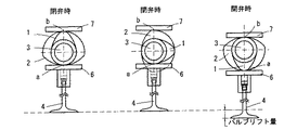
次に作用について説明する。図3は、この発明の請求項1の作動状態を示す直接駆動弁強制開閉装置の概略説明の側面図である。カムシャフト3に形成された開弁用カム1と閉弁用カム2が機関回転に同期して回転することにより、開弁用接触板6と閉弁用接触板7が接触点aで、又閉弁用カム2と閉弁用接触板7が接触点bで常時、摺接連動することでバルブユニット9を動かす、これにより低回転から高回転までバルブ4は常にカム1,2の動きに追動することにより、正確にバルブ4の開閉ができる。
Next, the operation will be described. FIG. 3 is a side view of a schematic explanation of the direct drive valve forced opening / closing device showing the operating state of
さらに、図4のAは請求項2の閉弁用カム2を複数にした実施形態の直接駆動弁強制開閉装置の断面図である。前記請求項1の実施形態のカムシャフト3に軸に形成された開弁用カム1を形成し、その両側に閉弁用カム2を形成する。その開弁用カム1に摺接連動する開弁用接触板6と両側の閉弁用カム2に摺接連動する閉弁用接触板7を設け、開弁用接触板6と閉弁用接触板7を連結部材8で繋ぐ、そして開弁用接触板6の下に前記開弁用接触板6によりバルブ4を押えるような構造でバルブ取り付け部5を設け、そこにバルブ4を取り付ける。
Further, FIG. 4A is a cross-sectional view of a direct drive valve forced opening / closing device of an embodiment in which a plurality of
さらに、図4のBは図4のAの開弁用カム1と閉弁用カム2の位置を逆にした場合の請求項2の実施形態、直接駆動弁強制開閉装置を示す断面図である。どちらの形態もバルブユニット9の駆動時の重心が中心に来るので、効果は同じであるが高速で安定して駆動できる。
FIG. 4B is a cross-sectional view showing the embodiment of
図5は、請求項3の実施形態の直接駆動弁強制開閉装置を示す断面図である。図5のAは請求項1と同じくカムシャフト3に軸に直交するように開弁用カム1と閉弁用カム2を形成する。その開弁用カム1に摺接連動する開弁用接触板6と閉弁用カム2に摺接連動する閉弁用接触板7を設け、開弁用接触板6と閉弁用接触板7を開弁用カム1と閉弁用カム2の間を通るように連結部材8で繋ぐ、そして開弁用接触板6の下に前記開弁用接触板6によりバルブ4を押えるような構造でバルブ取り付け部5を設け、そこにバルブ4を取り付ける。
FIG. 5 is a cross-sectional view showing a direct drive valve forced opening / closing device of an embodiment of
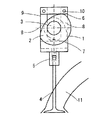
そして図6は請求項2の開弁用カム2を複数にした場合の請求項3の実施形態を示す断面図である、また図7は請求項3の実施形態の側面図である、カムシャフト3の軸に直交するように形成された開弁用カム1を形成し、その両側に閉弁用カム2を形成する。その開弁用カム1に摺接連動する開弁用接触板6と両側の閉弁用カム2に摺接連動する閉弁用接触板7を設け、連結部9を開弁用カム1と両側の閉弁用カム2の間を通し、開弁用接触板6と閉弁用接触板7を繋ぐ、このとき連結部材8と閉弁用接触板7をボルト又は固定ピン10で固定すると分解組み立てがしやすくなる。そして開弁用接触板6の下に前記開弁用接触板6によりバルブ4を押えるような構造でバルブ取り付け部5を設け、そこにバルブ4を取り付ける。また、開弁用カム1と閉弁用カム2の位置を逆にしても効果は同じである。(図示せず)
以上、本発明の実施例を説明したが、本発明は上記実施例に限定されるものではない、またこの発明は吸気弁、排気弁どちらでも使用可能である。
FIG. 6 is a cross-sectional view showing an embodiment of
Although the embodiments of the present invention have been described above, the present invention is not limited to the above embodiments, and the present invention can be used with either an intake valve or an exhaust valve.
本発明の直接駆動弁強制開閉装置は、頭上弁方式のすべての内燃機関に最適である。 The direct drive valve forced opening / closing device of the present invention is most suitable for all overhead valve internal combustion engines.
1 開弁用カム
2 閉弁用カム
3 カムシャフト
4 バルブ
5 バルブ取り付け部
6 開弁用接触板
7 閉弁用接触板
8 連結部材
9 バルブユニット
10固定ピン
11吸気管
1 Cam for
5
9
Claims (3)
Priority Applications (1)
| Application Number | Priority Date | Filing Date | Title |
|---|---|---|---|
| JP2007022918A JP2008190350A (en) | 2007-02-01 | 2007-02-01 | Forced opening/closing device for direct driven valve |
Applications Claiming Priority (1)
| Application Number | Priority Date | Filing Date | Title |
|---|---|---|---|
| JP2007022918A JP2008190350A (en) | 2007-02-01 | 2007-02-01 | Forced opening/closing device for direct driven valve |
Publications (2)
| Publication Number | Publication Date |
|---|---|
| JP2008190350A true JP2008190350A (en) | 2008-08-21 |
| JP2008190350A5 JP2008190350A5 (en) | 2010-03-04 |
Family
ID=39750683
Family Applications (1)
| Application Number | Title | Priority Date | Filing Date |
|---|---|---|---|
| JP2007022918A Abandoned JP2008190350A (en) | 2007-02-01 | 2007-02-01 | Forced opening/closing device for direct driven valve |
Country Status (1)
| Country | Link |
|---|---|
| JP (1) | JP2008190350A (en) |
Cited By (2)
| Publication number | Priority date | Publication date | Assignee | Title |
|---|---|---|---|---|
| JP2016037955A (en) * | 2014-08-10 | 2016-03-22 | 義輝 今村 | Cam shaft running torque reducing system |
| JP2016527433A (en) * | 2013-07-26 | 2016-09-08 | アイボス イノベーションズ ピーティーワイ リミテッド | Piston machine |
-
2007
- 2007-02-01 JP JP2007022918A patent/JP2008190350A/en not_active Abandoned
Cited By (2)
| Publication number | Priority date | Publication date | Assignee | Title |
|---|---|---|---|---|
| JP2016527433A (en) * | 2013-07-26 | 2016-09-08 | アイボス イノベーションズ ピーティーワイ リミテッド | Piston machine |
| JP2016037955A (en) * | 2014-08-10 | 2016-03-22 | 義輝 今村 | Cam shaft running torque reducing system |
Similar Documents
| Publication | Publication Date | Title |
|---|---|---|
| US8375904B2 (en) | Early intake valve closing and variable valve timing assembly and method | |
| KR101209733B1 (en) | Variable valve lift appratus | |
| JP6592325B2 (en) | Cylinder deactivation engine | |
| DE602006009469D1 (en) | Variable valve timing mechanism | |
| US7328680B1 (en) | Cylinder head assembly and spherical valve for internal combustion engines | |
| CA2494217A1 (en) | Valve operating system for internal combustion engine | |
| US8807101B2 (en) | Variable valve lift apparatus | |
| JP4286235B2 (en) | Variable valve mechanism for internal combustion engine | |
| EP1816320A3 (en) | Valve operating apparatus for internal combustion engine | |
| US9222375B2 (en) | Variable valve actuation apparatus, system, and method | |
| JP2008190350A (en) | Forced opening/closing device for direct driven valve | |
| KR100980872B1 (en) | Variable valve lift apparatus | |
| JP3097674U (en) | Piston air engine | |
| JP2008190350A5 (en) | ||
| Khan et al. | Design and development of variable valve timing and lift mechanism for improving the performance of single cylinder two wheeler gasoline engine | |
| JP2009024560A (en) | Control device for internal combustion engine | |
| JP4724009B2 (en) | Engine intake control device | |
| JP4551311B2 (en) | 4-cycle engine with internal EGR system | |
| US20050145212A1 (en) | Intake and exhaust system for engine | |
| JP2007205302A (en) | Intake air control device for engine | |
| JP2004278435A (en) | Positioning structure of rocker arm | |
| JP2007040232A (en) | Engine intake device | |
| CN107420148B (en) | Variable valve structure of motorcycle engine | |
| JP4312137B2 (en) | Valve mechanism with variable valve characteristics device | |
| JP4724008B2 (en) | Engine intake control device |
Legal Events
| Date | Code | Title | Description |
|---|---|---|---|
| A521 | Written amendment |
Free format text: JAPANESE INTERMEDIATE CODE: A523 Effective date: 20100114 |
|
| A621 | Written request for application examination |
Effective date: 20100114 Free format text: JAPANESE INTERMEDIATE CODE: A621 |
|
| A871 | Explanation of circumstances concerning accelerated examination |
Effective date: 20100114 Free format text: JAPANESE INTERMEDIATE CODE: A871 |
|
| RD02 | Notification of acceptance of power of attorney |
Free format text: JAPANESE INTERMEDIATE CODE: A7422 Effective date: 20100119 |
|
| A975 | Report on accelerated examination |
Free format text: JAPANESE INTERMEDIATE CODE: A971005 Effective date: 20100210 |
|
| A131 | Notification of reasons for refusal |
Effective date: 20100215 Free format text: JAPANESE INTERMEDIATE CODE: A131 |
|
| A762 | Written abandonment of application |
Free format text: JAPANESE INTERMEDIATE CODE: A762 Effective date: 20100507 |