EP2821138B1 - Flusszelle mit integrierter Trockensubstanz - Google Patents
Flusszelle mit integrierter Trockensubstanz Download PDFInfo
- Publication number
- EP2821138B1 EP2821138B1 EP13175335.2A EP13175335A EP2821138B1 EP 2821138 B1 EP2821138 B1 EP 2821138B1 EP 13175335 A EP13175335 A EP 13175335A EP 2821138 B1 EP2821138 B1 EP 2821138B1
- Authority
- EP
- European Patent Office
- Prior art keywords
- flow cell
- cavity
- support element
- passage
- support
- Prior art date
- Legal status (The legal status is an assumption and is not a legal conclusion. Google has not performed a legal analysis and makes no representation as to the accuracy of the status listed.)
- Active
Links
Images


Classifications
-
- B—PERFORMING OPERATIONS; TRANSPORTING
- B01—PHYSICAL OR CHEMICAL PROCESSES OR APPARATUS IN GENERAL
- B01L—CHEMICAL OR PHYSICAL LABORATORY APPARATUS FOR GENERAL USE
- B01L3/00—Containers or dishes for laboratory use, e.g. laboratory glassware; Droppers
- B01L3/50—Containers for the purpose of retaining a material to be analysed, e.g. test tubes
- B01L3/502—Containers for the purpose of retaining a material to be analysed, e.g. test tubes with fluid transport, e.g. in multi-compartment structures
- B01L3/5027—Containers for the purpose of retaining a material to be analysed, e.g. test tubes with fluid transport, e.g. in multi-compartment structures by integrated microfluidic structures, i.e. dimensions of channels and chambers are such that surface tension forces are important, e.g. lab-on-a-chip
- B01L3/502707—Containers for the purpose of retaining a material to be analysed, e.g. test tubes with fluid transport, e.g. in multi-compartment structures by integrated microfluidic structures, i.e. dimensions of channels and chambers are such that surface tension forces are important, e.g. lab-on-a-chip characterised by the manufacture of the container or its components
-
- B—PERFORMING OPERATIONS; TRANSPORTING
- B01—PHYSICAL OR CHEMICAL PROCESSES OR APPARATUS IN GENERAL
- B01L—CHEMICAL OR PHYSICAL LABORATORY APPARATUS FOR GENERAL USE
- B01L3/00—Containers or dishes for laboratory use, e.g. laboratory glassware; Droppers
- B01L3/50—Containers for the purpose of retaining a material to be analysed, e.g. test tubes
- B01L3/502—Containers for the purpose of retaining a material to be analysed, e.g. test tubes with fluid transport, e.g. in multi-compartment structures
- B01L3/5027—Containers for the purpose of retaining a material to be analysed, e.g. test tubes with fluid transport, e.g. in multi-compartment structures by integrated microfluidic structures, i.e. dimensions of channels and chambers are such that surface tension forces are important, e.g. lab-on-a-chip
-
- B—PERFORMING OPERATIONS; TRANSPORTING
- B01—PHYSICAL OR CHEMICAL PROCESSES OR APPARATUS IN GENERAL
- B01L—CHEMICAL OR PHYSICAL LABORATORY APPARATUS FOR GENERAL USE
- B01L2200/00—Solutions for specific problems relating to chemical or physical laboratory apparatus
- B01L2200/02—Adapting objects or devices to another
- B01L2200/026—Fluid interfacing between devices or objects, e.g. connectors, inlet details
- B01L2200/027—Fluid interfacing between devices or objects, e.g. connectors, inlet details for microfluidic devices
-
- B—PERFORMING OPERATIONS; TRANSPORTING
- B01—PHYSICAL OR CHEMICAL PROCESSES OR APPARATUS IN GENERAL
- B01L—CHEMICAL OR PHYSICAL LABORATORY APPARATUS FOR GENERAL USE
- B01L2200/00—Solutions for specific problems relating to chemical or physical laboratory apparatus
- B01L2200/04—Exchange or ejection of cartridges, containers or reservoirs
-
- B—PERFORMING OPERATIONS; TRANSPORTING
- B01—PHYSICAL OR CHEMICAL PROCESSES OR APPARATUS IN GENERAL
- B01L—CHEMICAL OR PHYSICAL LABORATORY APPARATUS FOR GENERAL USE
- B01L2200/00—Solutions for specific problems relating to chemical or physical laboratory apparatus
- B01L2200/06—Fluid handling related problems
- B01L2200/0689—Sealing
-
- B—PERFORMING OPERATIONS; TRANSPORTING
- B01—PHYSICAL OR CHEMICAL PROCESSES OR APPARATUS IN GENERAL
- B01L—CHEMICAL OR PHYSICAL LABORATORY APPARATUS FOR GENERAL USE
- B01L2200/00—Solutions for specific problems relating to chemical or physical laboratory apparatus
- B01L2200/10—Integrating sample preparation and analysis in single entity, e.g. lab-on-a-chip concept
-
- B—PERFORMING OPERATIONS; TRANSPORTING
- B01—PHYSICAL OR CHEMICAL PROCESSES OR APPARATUS IN GENERAL
- B01L—CHEMICAL OR PHYSICAL LABORATORY APPARATUS FOR GENERAL USE
- B01L2200/00—Solutions for specific problems relating to chemical or physical laboratory apparatus
- B01L2200/12—Specific details about manufacturing devices
-
- B—PERFORMING OPERATIONS; TRANSPORTING
- B01—PHYSICAL OR CHEMICAL PROCESSES OR APPARATUS IN GENERAL
- B01L—CHEMICAL OR PHYSICAL LABORATORY APPARATUS FOR GENERAL USE
- B01L2200/00—Solutions for specific problems relating to chemical or physical laboratory apparatus
- B01L2200/16—Reagents, handling or storing thereof
-
- B—PERFORMING OPERATIONS; TRANSPORTING
- B01—PHYSICAL OR CHEMICAL PROCESSES OR APPARATUS IN GENERAL
- B01L—CHEMICAL OR PHYSICAL LABORATORY APPARATUS FOR GENERAL USE
- B01L2300/00—Additional constructional details
- B01L2300/04—Closures and closing means
- B01L2300/041—Connecting closures to device or container
- B01L2300/044—Connecting closures to device or container pierceable, e.g. films, membranes
-
- B—PERFORMING OPERATIONS; TRANSPORTING
- B01—PHYSICAL OR CHEMICAL PROCESSES OR APPARATUS IN GENERAL
- B01L—CHEMICAL OR PHYSICAL LABORATORY APPARATUS FOR GENERAL USE
- B01L2300/00—Additional constructional details
- B01L2300/08—Geometry, shape and general structure
- B01L2300/0861—Configuration of multiple channels and/or chambers in a single devices
- B01L2300/0877—Flow chambers
-
- B—PERFORMING OPERATIONS; TRANSPORTING
- B01—PHYSICAL OR CHEMICAL PROCESSES OR APPARATUS IN GENERAL
- B01L—CHEMICAL OR PHYSICAL LABORATORY APPARATUS FOR GENERAL USE
- B01L2300/00—Additional constructional details
- B01L2300/12—Specific details about materials
- B01L2300/123—Flexible; Elastomeric
-
- B—PERFORMING OPERATIONS; TRANSPORTING
- B01—PHYSICAL OR CHEMICAL PROCESSES OR APPARATUS IN GENERAL
- B01L—CHEMICAL OR PHYSICAL LABORATORY APPARATUS FOR GENERAL USE
- B01L2300/00—Additional constructional details
- B01L2300/16—Surface properties and coatings
- B01L2300/161—Control and use of surface tension forces, e.g. hydrophobic, hydrophilic
- B01L2300/163—Biocompatibility
Definitions
- the invention relates to a microfluidic flow cell, comprising a dry substance disposed in a cavity within the flow cell for interaction with a fluid in the cavity, wherein the cavity is bounded by a recess in a substrate and a cover closing the recess and wherein the flow cell is a separate Carrier element comprises a provided for the arrangement adjacent to the cavity support surface for the dry matter.
- Microfluidic flow cells which are increasingly being used as a "mini-laboratory" for the analysis or / and synthesis of fluids, in particular in diagnostics, contain reaction substances in liquid or / and solid form, which are to be introduced into the flow cells during the production of the flow cells.
- a reagent liquid to be dried is brought to the relevant point in an assembly step in which the area provided for receiving the dry reagent within the flow cell, eg a channel or a chamber, is still accessible, ie a carrier liquid having dissolved therein or suspended reagent.
- the entire, only partially wetted with the reagent liquid component of the flow cell prior to further assembly is subjected to a drying process, which is often associated with a heat treatment for the purpose of acceleration or to protect the reagents and in terms of stability and Resuspend istseigenschaften as freeze drying process.
- a drying process which is often associated with a heat treatment for the purpose of acceleration or to protect the reagents and in terms of stability and Resuspend istseigenschaften as freeze drying process.
- the disadvantage is that the component, whose dimensions mostly far exceed those of the area to be dried only, has a large space in a drying chamber. Further, the drying treatment of this component of the flow cell itself affect, especially mounted on sensitive components.
- the dry substance formed may then be impaired by air contact, in particular humidity, and welding heat or the influence of the adhesive used in the assembly, in many cases hermetically closing the corresponding channel regions of a microfluidic flow cell.
- a method for introducing a dry substance into a flow cell, as described above, is for example from the EP 2 198 964 B1 out.
- From the DE 10 2008 021 364 A1 shows a flow cell in which recesses in a substrate are closed by a foil cover.
- the film cover carries on the inside dry reagents, which face the cavities formed by the covered recesses.
- a flow cell of the type mentioned starts from the WO 2012/154 306 A1 out.
- the flow cell has a cavity, which is accessible after opening a hatch or flap and having a recess in a bottom for receiving a cuboid support member. During operation of the flow cell, the hatch or flap must be closed.
- the invention has for its object to provide a new microfluidic flow cell of the type mentioned with an integrated dry matter, which can be more easily produced than in the prior art without affecting the dry matter or other components of the flow cell through the manufacturing environment.
- the problem solved flow cell according to the invention is characterized in that in the cavity leads to an outer surface of the flow cell guided, outwardly open passage and that the separate support member from the outside under closure of the cavity and the arrangement of the support surface adjacent to the cavity in the passage can be used.
- the formation of the dry substance by drying a reagent liquid can be carried out separately from the entire remaining flow cell on a support element, which alone serves to absorb the dry matter and allows the introduction of the dry matter in the flow cell in a final assembly step. Impairment of components of the flow cell by the drying process As well as impairments of the introduced dry reagent by further assembly work on the flow cell accounts.
- the carrier element can have substantially smaller dimensions than the flow cell, wherein the dimensions of the carrier element are based on the size of the area carrying the dry reagent.
- the adhesion of the dry substance on its carrier surface-promoting coatings can be advantageously limited to the carrier surface of the carrier element remain so that impairments of welding or adhesive joints are excluded by such coatings.
- the cavity may form a channel network for the transport, analysis or / and synthesis of a fluid.
- carrier elements possibly with different dry substances, can be used.
- the cavity is defined by a recess in a plate-shaped substrate and a recess closing the recess, limited foil-like cover.
- the passage is formed in the thicker compared to the film-like cover substrate.
- passage is expediently guided to an outer surface of the flow cell, so that the introduction of the dry substance into the flow cell during its production can take place in a final assembly step.
- the carrier element is preferably designed such that it can be detachably and / or permanently connected to the flow cell while closing the cavity.
- the passage is adapted in shape to the shape of the carrier element. Fluid tightness can be achieved in particular by welding or / and gluing, possibly also only by mechanical impressions of the carrier element in the passage.
- the carrier element expediently completely fills the passage, at least in cross-section, wherein the carrier element and the passage in cross-section preferably have a production-advantageous circular shape.
- the carrier element tapers towards the cavity while the passage narrows.
- a tight closure of the cavity in the form of a press fit can be achieved solely by mechanical impressions of the carrier element in the passage.
- the support member has a portion projecting outwardly of the flow cell, which may serve as a handle portion for ease of manual handling or automated assembly.
- the projecting portion may overlap the flow cell in the manner of a collar on the outside, whereby an additional sealing of the cavity can be achieved by the collar.
- the carrier element can be screwed into the passage.
- the support surface of the support member may be flush or recessed to an adjacent wall surface of the cavity. Alternatively, the support member projects from the adjacent wall surface into the cavity.
- the carrier surface expediently has a structuring, coating or / and surface modification promoting the adhesion of the dry substance.
- the carrier element and the carrier surface carrying the dry reagent are preferably made of plastic.
- the support surface may be formed by a separate, connected to the rest of the support member surface member made of glass, silicon, ceramic or metal and applied by welding or gluing. This is advantageous if surface properties that are realizable for the application of the dry reagent other than by a plastic surface or coating are necessary.
- the dry reagents include salts, buffers e.g. for cell lysis, magnetic and non-magnetic beads, enzymes, antibodies, DNA fragments, proteins, PCR reagents or, alternatively, cells into consideration.
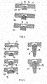
- the flow cell shown in detail comprises a plate-shaped substrate 1 with a recess 2, which is covered to form a cavity 3 by a film 4 bonded or / and welded to the substrate.
- the cavity 3 is part of an in Fig. 1 otherwise not shown channel network of the flow cell, in particular it forms a channel region in which a dry reagent 5 having antibodies, for example, adheres to a channel wall 6.
- Thenreagenz 5 comes from a before the cover of the recess 2 through the film 4 in a channel or chamber region of the flow cell forming recess 2 by dispensing reagent introduced 7.
- the entire substrate 1 was a heat treatment or / and lyophilized.
- a cavity 3 in a flow cell which is, for example, a region of an in Fig. 3 shown channel 9, has a passage opening 10, in which the carrier element 8 with a conical, a support surface 13 for the dry reagent 5 having portion 11 is used under fluid-tight closure of the cavity 3.
- the support surface 13 forms a part of the wall surface of the cavity 3 after assembly.
- a fluid transported or processed in the cavity 3 can thus interact with the dry reagent, in particular the dry reagent can be dissolved and resuspended by the fluid.
- constituents of the fluid such as cells or analytes, can interact and / or bind with the dry reagent by the fluid, possibly several times with change of the transport direction, overflowing the carrier surface.
- the support element 8 fitted in the passage opening 10 may be glued or welded to the substrate. A beyond the passage opening 10 on the side facing away from the cavity 3 of the substrate 1 protruding portion 12 of the support member 8 serves as the mounting of the support member 8 facilitating handle part.
- Fig. 1 does not need to form the dry reagent 5 from a reagent liquid 7 as in the example of Fig. 1 to be exposed to drying the entire substrate 1, but only the carrier element 8, which saves space in a drying chamber.
- the main components of the flow cell, the substrate 1 and the film 4 are not subject to any stress caused by the drying process and finally introduced into the flow cell dry matter 5 no impairment by a subsequent completion of the flow cell with welding of substrate 1 and film 4.
- Fig. 3 may be present in the channel 9 a plurality of openings for receiving carrier elements 8 with possibly different dry reagents 5 arranged thereon.
- Fig. 3 serves the meandering channel 9 of the return of the introduced by the support members 8 dry reagents 5 by mutual overflow.
- the substrate 1 and the film 4 of the flow cell are preferably made of a plastic, in particular both of the same plastic, for which purpose e.g. PMMA, PC, PS, PEEK, PP, PE, COC and COP.
- the carrier element 8 is preferably a plastic part, which consists in particular of the same plastic as the substrate. The preparation of the substrate and the carrier elements made of plastic is expediently carried out by injection molding.
- Fig. 4 can remove the dry reagent 5 receiving support surface 13 of the support member 8 to the adjacent wall surface 14 of the cavity 3 is flush or set back to this wall surface.
- the carrier element 8 with the carrier surface 13 can also protrude into the cavity 3. This may be advantageous for locally generating turbulences in a laminar flow normally present in microchannels by abruptly changing the channel cross section and / or increasing the flow velocity of the fluid in the channel region into which the carrier element 8 is introduced by reducing the channel cross section achieve, for example, to accelerate and control a re-dissolution of the dry reagent.
- Fig. 5 shows further embodiments of carrier elements 8, which according to Fig. 5a cylindrical and according to Fig. 5b can be cylindrical with a collar 15 engaging behind the substrate 1.
- Fig. 5c shows an embodiment of a cylindrical, a collar 13 having support member 8 with an external thread 16 which engages in an internal thread in the respective passage opening.
- the carrier element 8 can be detached from the flow cell, if not in addition to Screw connection even a bonding or welding with the substrate 1 takes place.
- the solubility can be advantageous if the dry reagent after interaction with the fluid to be separated again from the flow cell and subjected to further analysis.
- a detachable from the flow cell support member 8 with an extended handle portion 17 shows Fig. 5e ,
- the carrier element 8 can be pressed under fluid-tight closure of the cavity 3 in the respective passage opening in the substrate 1.
- the guidance of the carrier element 8 can be improved.
- Fig. 5d shows a support member 8 with a conical portion and a projecting from a through hole collar 15 which is sealed against the substrate 1 by a ring seal 18.
- the rotationally symmetrical support elements may have a marking which makes it possible to introduce the support elements in a desired rotational position in the passage.
- Fig. 6 go embodiments of support elements 8 with differently shaped support surfaces 13, wherein Fig. 6a a carrier element with a recess 19 for receiving a dry reagent 5 has.
- a support surface 13 is formed with a plurality of receiving recesses in the form of cross-shaped grooves 20 with typical cross-sectional dimensions of 0.01 x 0.01 mm 2 to 1 x 1 mm 2 for a dry reagent.
- the surface of the support surface 13 can thereby be enlarged in a simple manner, so that either a larger amount of dry reagent 5 can be taken up with the same dimensions of the support element 8 and / or the dry substance can dry more homogeneously than a large drop on a smooth support surface.
- Fig. 6c shows a receiving surface with a force applied to the support surface by clamping, gluing or welding porous element 21, in which a Can settle dry substance.
- the porous element 21 forms an enlarged surface for receiving the dry reagent 5.
- Fig. 6d has a carrier element with a treated carrier surface, wherein the treatment may be, for example, a wet-chemical treatment, a plasma treatment or corona treatment.
- the treatment can lead to a coating 22, for example by means of plasma polymerization or by PVD process, for example a glass or metal coating.
- An in Fig. 6e shown carrier component is formed in two parts with a separate surface component 26.
- the surface component 26 forming the carrier surface does not consist of a plastic, for example, but preferably the rest of the carrier component, but of glass, silicon, metal or ceramic.
- functionalization ie application of the dry reagent to the support surface, requires such materials, as is the case for example with protein (eg antibody) or nucleic acid based analysis technologies, the use of these materials, which are often significantly more expensive than plastic, is limited. advantageous only to a surface area, with dimensions of 0.5 x 0.5 mm to 5 x 5 mm and thicknesses between 0.1 and 1 mm into consideration.
- the surface member 26 may be fixed to the remaining support member by means of clamping or by gluing or welding.
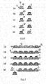
- a multiplicity of carrier elements 8 can be processed simultaneously by arranging the carrier elements 8 on a carrier plate 24 having a row of holes 23 in step 7a.
- a layer 22 which improves the adhesion of a substance is simultaneously produced on all carrier surfaces 13 of the carrier elements 8.
- the coating can also cover other, not provided for applying thezelreagenz 5 surface areas of the support member 8.
- steps 7c and 7d after application of a reagent liquid 7 to the layers 22, a drying treatment takes place so that the dry substance 5 adhering to the layers 22 is deposited on the layers 22.
- step 7e the finished carrier elements 8 provided with a dry substance 5 can be removed for processing.
- FIG. 8 Reference is made, where a further embodiment for a carrier element 8 is shown.
- the carrier element 8 has a carrier surface for a dry substance 5, which is formed by a membrane 27.
- This membrane can be integrally connected to the rest of the carrier element 8 or formed by a separate, connected to the rest of the carrier element component, which preferably consists of the same plastic as the rest of the carrier element.
Landscapes
- Chemical & Material Sciences (AREA)
- Health & Medical Sciences (AREA)
- Dispersion Chemistry (AREA)
- Analytical Chemistry (AREA)
- General Health & Medical Sciences (AREA)
- Hematology (AREA)
- Clinical Laboratory Science (AREA)
- Chemical Kinetics & Catalysis (AREA)
- Apparatus Associated With Microorganisms And Enzymes (AREA)
- Sampling And Sample Adjustment (AREA)
- Secondary Cells (AREA)
- Physical Or Chemical Processes And Apparatus (AREA)
Description
- Die Erfindung betrifft eine mikrofluidische Flusszelle, mit einer innerhalb der Flusszelle in einem Hohlraum angeordneten Trockensubstanz zur Wechselwirkung mit einem in dem Hohlraum befindlichen Fluid, wobei der Hohlraum durch eine Ausnehmung in einem Substrat und eine die Ausnehmung verschließende Abdeckung begrenzt ist und wobei die Flusszelle ein separates Trägerelement mit einer zur Anordnung angrenzend an den Hohlraum vorgesehenen Trägerfläche für die Trockensubstanz umfasst.
- Mikrofluidische Flusszellen, wie sie zunehmend als "Minilabor" zur Analyse oder/und Synthese von Fluiden insbesondere in der Diagnostik zum Einsatz kommen, enthalten Reaktionssubstanzen in flüssiger oder/und fester Form, die während der Herstellung der Flusszellen in die Flusszellen einzubringen sind.
Zur Einbringung einer Trockenreagenz wird in einem Montageschritt, in welchem der für die Aufnahme der Trockenreagenz innerhalb der Flusszelle vorgesehene Bereich, z.B. eines Kanals oder einer Kammer, noch zugänglich ist, an die betreffende Stelle eine zu trocknende Reagenzflüssigkeit gebracht, d.h. eine Trägerflüssigkeit mit darin gelöster oder suspendierter Reagenz. Danach ist das gesamte, mit der Reagenzflüssigkeit nur stellenweise benetzte Bauteil der Flusszelle vor deren weiterer Montage einem Trocknungsprozess zu unterziehen, der zwecks Beschleunigung oftmals mit einer Wärmebehandlung verbunden ist oder zur Schonung der Reagenzien sowie im Hinblick auf Stabilität und Resuspendierungseigenschaften als Gefriertrocknungsprozess erfolgt. Nachteilig belegt das Bauteil, dessen Abmessungen diejenigen des nur zu trocknenden Bereichs zumeist weit überschreiten, in einer Trocknungskammer viel Raum. Ferner kann die Trocknungsbehandlung dieses Bauteil der Flusszelle selbst beeinträchtigen, insbesondere daran montierte empfindliche Komponenten. Vor allem kann die gebildete Trockensubstanz dann im Zuge der Fertigmontage der Flusszelle Beeinträchtigungen durch Luftkontakt, insbesondere Luftfeuchtigkeit, und Schweißwärme oder dem Einfluss bei der Montage verwendeter Klebemittel unterliegen, durch die entsprechende Kanalbereiche einer mikrofluidischen Flusszelle in vielen Fällen hermetisch zu verschließen sind. Ein Verfahren zum Einbringen einer Trockensubstanz in eine Flusszelle, wie es vorangehend beschrieben ist, geht z.B. aus derEP 2 198 964 B1 hervor. - Aus der
DE 10 2008 021 364 A1 geht eine Flusszelle hervor, bei der Ausnehmungen in einem Substrat durch eine Folienabdeckung verschlossen sind. Die Folienabdeckung trägt auf der Innenseite Trockenreagenzien, die den durch die abgedeckten Ausnehmungen gebildeten Hohlräumen zugewandt sind. - Eine Flusszelle der eingangs erwähnten Art geht aus der
WO 2012/154 306 A1 hervor. Die Flusszelle weist einen Hohlraum auf, der nach Öffnung eine Luke oder Klappe zugänglich ist und in einem Boden eine Vertiefung für die Aufnahme eines quaderförmigen Trägerelements aufweist. Im Betrieb der Flusszelle ist die Luke bzw. Klappe zu verschließen. - Der Erfindung liegt die Aufgabe zugrunde, eine neue mikrofluidische Flusszelle der eingangs genannten Art mit einer integrierten Trockensubstanz zu schaffen, die sich leichter als nach dem Stand der Technik ohne Beeinträchtigungen der Trockensubstanz oder anderer Bestandteile der Flusszelle durch die Fertigungsumgebung herstellen lässt.
- Die diese Aufgabe lösende Flusszelle nach der Erfindung ist dadurch gekennzeichnet, dass in dem Hohlraum ein zu einer Außenfläche der Flusszelle geführter, ach außen offener Durchgang mündet und dass das separate Trägerelement von außen unter Verschluss des Hohlraums und unter Anordnung der Trägerfläche angrenzend an den Hohlraum in den Durchgang einsetzbar ist.
- Vorteilhaft kann die Bildung der Trockensubstanz durch Trocknung einer Reagenzflüssigkeit getrennt von der gesamten übrigen Flusszelle an einem Trägerelement erfolgen, das allein der Aufnahme der Trockensubstanz dient und die Einbringung der Trockensubstanz in die Flusszelle in einem abschließenden Montageschritt erlaubt. Beeinträchtigungen von Bauteilen der Flusszelle durch den Trocknungsprozess sowie Beeinträchtigungen der eingebrachten Trockenreagenz durch weitere Montagearbeiten an der Flusszelle entfallen. Das Trägerelement kann wesentlich kleinere Abmessungen als die Flusszelle aufweisen, wobei sich die Abmessungen des Trägerelements an der Größe des die Trockenreagenz tragenden Bereichs orientieren. Die Anhaftung der Trockensubstanz an ihrer Trägerfläche fördernde Beschichtungen können vorteilhaft auf die Trägerfläche des Trägerelements beschränkt bleiben, sodass Beeinträchtigungen von Schweiß- oder Klebeverbindungen durch solche Beschichtungen auszuschließen sind.
- Es versteht sich, dass der Hohlraum ein Kanalnetzwerk zum Transport, zur Analyse oder/und Synthese eines Fluids bilden kann. In die Flusszelle können mehrere Trägerelemente, ggf. mit unterschiedlichen Trockensubstanzen, einsetzbar sein.
- In einer Ausführungsform der Erfindung ist der Hohlraum durch eine Ausnehmung in einem plattenförmigen Substrat und eine die Ausnehmung verschließende, folienartig ausgebildete Abdeckung begrenzt. Der Durchgang ist in dem im Vergleich zur folienartigen Abdeckung dickeren Substrat gebildet.
- Es versteht sich, dass der Durchgang zweckmäßig zu einer Außenfläche der Flusszelle geführt ist, sodass die Einbringung der Trockensubstanz in die Flusszelle bei deren Herstellung in einem letzten Montageschritt erfolgen kann.
- Das Trägerelement ist vorzugsweise so gestaltet, dass es sich unter Verschluss des Hohlraums mit der Flusszelle lösbar und/oder unlösbar verbinden lässt. Vorzugsweise ist der Durchgang in seiner Form an die Form des Trägerelements angepasst. Fluiddichtheit kann insbesondere durch Einschweißen oder/und Einkleben erreicht werden, ggf. auch nur durch mechanisches Eindrücken des Trägerelements in den Durchgang.
- Entsprechend füllt zweckmäßig das Trägerelement den Durchgang zumindest im Querschnitt vollständig aus, wobei das Trägerelement und der Durchgang im Querschnitt vorzugsweise eine fertigungstechnisch vorteilhafte Kreisform aufweisen.
- In weiterer Ausgestaltung der Erfindung verjüngt sich das Trägerelement zu dem Hohlraum hin, während sich der Durchgang verengt. Insbesondere kann so allein durch mechanisches Eindrücken des Trägerelements in den Durchgang ein dichter Verschluss des Hohlraums in Form einer Presspassung erreicht werden.
- Vorzugsweise weist das Trägerelement einen von der Flusszelle nach außen vorstehenden Abschnitt auf, der als Griffteil zur Vereinfachung einer manuellen Handhabung oder automatisierten Montage dienen kann.
- Der vorstehende Abschnitt kann die Flusszelle in der Art eines Kragens außenseitig übergreifen, wobei durch den Kragen eine zusätzliche Abdichtung des Hohlraums erreicht werden kann.
- In einer weiteren Ausführungsform ist das Trägerelement in den Durchgang einschraubbar.
- Die Trägerfläche des Trägerelements kann bündig oder zurückversetzt zu einer angrenzenden Wandoberfläche des Hohlraums angeordnet sein. Alternativ steht das Trägerelement von der angrenzenden Wandoberfläche in den Hohlraum hinein vor.
- Zweckmäßig weist die Trägerfläche eine die Anhaftung der Trockensubstanz fördernde Strukturierung, Beschichtung oder/und Oberflächenmodifizierung auf.
- Das Trägerelement und die die Trockenreagenz tragende Trägerfläche besteht bevorzugt aus Kunststoff. Alternativ kann die Trägerfläche durch ein separates, mit dem übrigen Trägerelement verbundenes Oberflächenbauteil aus Glas, Silizium, Keramik oder Metall gebildet sein und mittels Schweißen oder Kleben aufgebracht werden. Dies ist vorteilhaft, wenn andere als durch eine Kunststoffoberfläche oder Beschichtung realisierbare Oberflächeneigenschaften für das Aufbringen der Trockenreagenz notwendig sind.
- Als Trockenreagenzien kommen unter anderem Salze, Puffer z.B. für die Zelllyse, magnetische und nicht magnetische Beads, Enzyme, Antikörper, DNA-Fragmente, Proteine, PCR-Reagenzien oder alternativ auch Zellen in Betracht.
- Die Erfindung wird nachfolgend anhand von Ausführungsbeispielen und der beiliegenden, sich auf diese Ausführungsbeispiele beziehenden Zeichnungen weiter erläutert. Es zeigen:
- Fig. 1
- eine die Herstellung von Flusszellen mit integrierter Trockensubstanz nach dem Stand der Technik erläuternde Darstellung,
- Fig. 2
- eine die Herstellung einer erfindungsgemäßen Flusszelle erläuternde Darstellung,
- Fig. 3
- eine Detaildarstellung der in
Fig. 2 gezeigten Flusszelle, - Fig. 4
- Ausführungsbeispiele für die Anordnung einer Trägerfläche eines Träger-elements innerhalb eines Hohlraums einer Flusszelle,
- Fig. 5
- weitere Ausführungsbeispiele für erfindungsgemäße Trägerelemente,
- Fig. 6
- Ausführungsbeispiele für Trägeroberflächen von Trägerelementen,
- Fig. 7
- eine die Aufbringung einer Trockensubstanz auf Trägerelemente erläuternde Darstellung, und
- Fig. 8
- ein weiteres Ausführungsbeispiel für ein erfindungsgemäßes Trägerelement.
- Eine in
Fig. 1 ausschnittsweise gezeigte Flusszelle umfasst ein plattenförmiges Substrat 1 mit einer Ausnehmung 2, die unter Bildung eines Hohlraums 3 durch eine mit dem Substrat verklebte oder/und verschweißte Folie 4 abgedeckt ist. Der Hohlraum 3 ist Teil eines inFig. 1 im Übrigen nicht dargestellten Kanalnetzwerks der Flusszelle, insbesondere bildet er einen Kanalbereich, in dem eine z.B. Antikörper aufweisende Trockenreagenz 5 an einer Kanalwand 6 anhaftet. - Die Trockenreagenz 5 entstammt einer vor der Abdeckung der Ausnehmung 2 durch die Folie 4 in die einen Kanal- oder Kammerbereich der Flusszelle bildende Ausnehmung 2 durch Dispensierung eingebrachten Reagenzflüssigkeit 7. Zur Bildung der Trockenreagenz 5 aus der Reagenzflüssigkeit 7 wurde das gesamte Substrat 1 einer Wärmebehandlung oder/und Gefriertrocknung unterzogen.
- Aus
Fig. 2 geht ein Verfahren zur Einbringung einer Trockensubstanz, insbesondere einer Trockenreagenz 5, in eine Flusszelle hervor, bei welchem die Trockenreagenz 5 auf ein separates Trägerteil 8 aufgebracht wird. Ein Hohlraum 3 in einer Flusszelle, bei dem es sich z.B. um einen Bereich eines inFig. 3 gezeigten Kanals 9 handeln kann, weist eine Durchgangsöffnung 10 auf, in welche das Trägerelement 8 mit einem konischen, eine Trägerfläche 13 für die Trockenreagenz 5 aufweisenden Abschnitt 11 unter fluiddichtem Verschluss des Hohlraums 3 einsetzbar ist. Die Trägerfläche 13 bildet nach der Montage einen Teil der Wandfläche des Hohlraums 3. Ein im Hohlraum 3 transportiertes oder verarbeitetes Fluid kann so in Wechselwirkung mit der Trockenreagenz treten, insbesondere kann die Trockenreagenz von dem Fluid aufgelöst und resuspendiert werden. Andererseits können Bestandteile des Fluids wie Zellen oder Analyten mit der Trockenreagenz interagieren und/oder daran binden, indem das Fluid, ggf. mehrmals unter Wechsel der Transportrichtung, die Trägerfläche überströmt. - Das in die Durchgangsöffnung 10 eingepasste Trägerelement 8 kann mit dem Substrat verklebt oder verschweißt sein. Ein über die Durchgangsöffnung 10 hinaus auf der dem Hohlraum 3 abgewandten Seite des Substrats 1 vorstehender Abschnitt 12 des Trägerelements 8 dient als die Montage des Trägerelements 8 erleichternder Griffteil.
- Im Unterschied zu dem den Stand der Technik betreffenden Beispiel von
Fig. 1 braucht zur Bildung der Trockenreagenz 5 aus einer Reagenzflüssigkeit 7 nicht wie bei dem Beispiel vonFig. 1 das gesamte Substrat 1 einer Trocknung ausgesetzt zu werden, sondern lediglich das Trägerelement 8, was Platz in einer Trockenkammer spart. Die Hauptbauteile der Flusszelle, das Substrat 1 und die Folie 4 unterliegen keiner Beanspruchung durch den Trocknungsvorgang und die abschließend in die Flusszelle eingebrachte Trockensubstanz 5 keiner Beeinträchtigung durch eine nachträglich erfolgende Fertigstellung der Flusszelle unter Verschweißung von Substrat 1 und Folie 4. - Wie
Fig. 3 erkennen lässt, können in dem Kanal 9 mehrere Öffnungen für die Aufnahme von Trägerelementen 8 mit ggf. unterschiedlichen darauf angeordneten Trockenreagenzien 5 vorhanden sein. In dem Beispiel vonFig. 3 dient der mäanderförmige Kanal 9 der Rücklösung der durch die Trägerelemente 8 eingebrachten Trockenreagenzien 5 durch wechselseitiges Überspülen. - Das Substrat 1 und die Folie 4 der Flusszelle bestehen vorzugsweise aus einem Kunststoff, insbesondere beide aus dem gleichen Kunststoff, wobei hierfür z.B. PMMA, PC, PS, PEEK, PP, PE, COC und COP in Betracht kommen. Auch bei dem Trägerelement 8 handelt es sich vorzugsweise um ein Kunststoffteil, das insbesondere aus dem gleichen Kunststoff wie das Substrat besteht. Die Herstellung des Substrats und der Trägerelemente aus Kunststoff erfolgt zweckmäßig durch Spritzgießen.
- Wie sich
Fig. 4 entnehmen lässt, kann die die Trockenreagenz 5 aufnehmende Trägerfläche 13 des Trägerelements 8 zu der angrenzenden Wandfläche 14 des Hohlraums 3 bündig oder zu dieser Wandfläche zurückversetzt sein. GemäßFig. 4b kann das Trägerelement 8 mit der Trägerfläche 13 auch in den Hohlraum 3 hinein vorstehen. Dies kann vorteilhaft sein, um in einer in Mikrokanälen normalerweise vorliegenden laminaren Strömung lokal durch abrupte Änderung des Kanalquerschnitts Turbulenzen zu erzeugen und/oder um in dem Kanalbereich, in den das Trägerelement 8 eingebracht ist, durch Verkleinerung des Kanalquerschnitts eine Vergrößerung der Fließgeschwindigkeit des Fluids zu erreichen, z.B. zur Beschleunigung und Steuerung einer Rücklösung der Trockenreagenz. Ferner ergibt sich der Vorteil, dass bei einer automatisierten Montage des Trägerelements 8 Montage- und/oder Bauteiltoleranzen ausgleichbar sind. -
Fig. 5 zeigt weitere Ausführungsformen für Trägerelemente 8, die gemäßFig. 5a zylindrisch und gemäßFig. 5b zylindrisch mit einem das Substrat 1 hintergreifenden Kragen 15 ausgebildet sein können. -
Fig. 5c zeigt eine Ausführungsform eines zylindrischen, einen Kragen 13 aufweisenden Trägerelements 8 mit einem Außengewinde 16, das in ein Innengewinde in der betreffenden Durchgangsöffnung eingreift. Vorteilhaft lässt sich bei letzterer Ausführungsform das Trägerelement 8 von der Flusszelle lösen, sofern nicht zusätzlich zur Schraubverbindung auch noch eine Verklebung oder Verschweißung mit dem Substrat 1 erfolgt. Die Lösbarkeit kann vorteilhaft sein, wenn die Trockenreagenz nach Wechselwirkung mit dem Fluid wieder von der Flusszelle getrennt und einer weiteren Analyse unterzogen werden soll. - Ein von der Flusszelle lösbares Trägerelement 8 mit einem verlängerten Griffteil 17 zeigt
Fig. 5e . Das Trägerelement 8 lässt sich unter fluiddichtem Verschluss des Hohlraums 3 in die betreffende Durchgangsöffnung in dem Substrat 1 eindrücken. - Durch einen erhabenen Rand 25 gemäß
Fig. 5f am Substrat 1, dessen Dicke typischerweise zwischen 0,5 und 3 mm beträgt, lässt sich die Führung des Trägerelements 8 verbessern. -
Fig. 5d zeigt ein Trägerelement 8 mit einem konischen Abschnitt und einem aus einer Durchgangsöffnung vorstehenden Kragen 15, der gegen das Substrat 1 durch eine Ringdichtung 18 abgedichtet ist. - Die rotationssymmetrischen Trägerelemente können eine Markierung aufweisen, die es ermöglicht, die Trägerelemente in einer gewünschten Drehposition in den Durchgang einzuführen.
- Aus
Fig. 6 gehen Ausführungsbeispiele von Trägerelementen 8 mit unterschiedlich gestalteten Trägerflächen 13 hervor, wobeiFig. 6a ein Trägerelement mit einer Vertiefung 19 für die Aufnahme einer Trockenreagenz 5 aufweist. Bei dem Ausführungsbeispiel vonFig. 6b ist eine Trägerfläche 13 mit einer Vielzahl von Aufnahmevertiefungen in Form von kreuzartig angeordneten Rillen 20 mit typischen Querschnittsabmessungen von 0,01 x 0,01 mm2 bis 1 x 1 mm2 für eine Trockenreagenz gebildet. Vorteilhaft lässt sich dadurch die Oberfläche der Trägerfläche 13 auf einfache Art und Weise vergrößern, sodass entweder eine größere Menge an Trockenreagenz 5 bei gleichen Abmessungen des Trägerelements 8 aufgenommen werden oder/und die Trockensubstanz homogener als ein großer Tropfen auf einer glatten Trägerfläche eintrocknen kann und/oder die durch die Aufnahmevertiefungen 20 gebildete Mikrostruktur der Trägerfläche 13 beim Überströmen durch das Fluid Turbulenzen erzeugen kann, welche das Rücklöseverhalten positiv beeinflussen. Die Rillen könnten alternativ auch die Form konzentrischer Kreise aufweisen.Fig. 6c zeigt eine Aufnahmefläche mit einem auf die Trägerfläche durch Klemmen, Kleben oder Schweißen aufgebrachten porösen Element 21, in dem sich eine Trockensubstanz absetzen kann. Vorteilhaft bildet das poröse Element 21 eine vergrößerte Oberfläche für die Aufnahme der Trockenreagenz 5. -
Fig. 6d weist ein Trägerelement mit einer behandelten Trägerfläche auf, wobei es sich bei der Behandlung z.B. um eine nasschemische Behandlung, eine Plasmabehandlung oder Koronabehandlung handeln kann. Alternativ kann die Behandlung z.B. mittels Plasmapolymerisation oder mittels PVD-Prozess zu einer Beschichtung 22 führen, z.B. einer Glas- oder Metallbeschichtung. - Ein in
Fig. 6e gezeigtes Trägerbauteil ist zweiteilig mit einem gesonderten Oberflächenbauteil 26 ausgebildet. Das die Trägeroberfläche bildende Oberflächenbauteil 26 besteht z.B. nicht wie vorzugsweise das übrige Trägerbauteil aus einem Kunststoff, sondern aus Glas, Silizium, Metall oder Keramik. Wenn die Funktionalisierung, d.h. die Aufbringung der Trockenreagenz auf die Trägerfläche, solche Materialien erfordert, wie das z.B. bei Protein- (z.B. Antikörper) oder Nukleinsäurebasierten Analysetechnologien der Fall ist, so beschränkt sich die Verwendung dieser Materialien, die oft deutlich teurer als Kunststoff sind, vorteilhaft nur auf einen Oberflächenbereich, wobei Abmessungen von 0,5 x 0,5 mm bis 5 x 5 mm und Dicken zwischen 0,1 und 1 mm in Betracht kommen. Das Oberflächenbauteil 26 kann auf dem übrigen Trägerbauteil mittels Klemmen oder durch Kleben oder Schweißen befestigt werden. - Zum Aufbringen der Trockensubstanz 5 lässt sich eine Vielzahl von Trägerelementen 8 gleichzeitig bearbeiten, indem die Trägerelemente 8 im Schritt 7a auf einem Reihen von Löchern 23 aufweisenden Trägertablet 24 angeordnet werden. Im nächstfolgenden Verfahrensschritt 7b wird gleichzeitig auf allen Trägerflächen 13 der Trägerelemente 8 eine die Haftung einer Substanz verbessernde Schicht 22 erzeugt. Die Beschichtung kann dabei auch andere, nicht zum Aufbringen der Trockenreagenz 5 vorgesehene Oberflächenbereiche des Trägerelements 8 bedecken. In den Verfahrensschritten 7c und 7d erfolgt nach Auftragen einer Reagenzflüssigkeit 7 auf die Schichten 22 eine Trocknungsbehandlung, sodass sich auf den Schichten 22 die daran anhaftende Trockensubstanz 5 absetzt. Schließlich können im Schritt 7e die fertiggestellten, mit einer Trockensubstanz 5 versehenen Trägerelemente 8 zur Verarbeitung entnommen werden.
- Es wird nun auf
Fig. 8 Bezug genommen, wo ein weiteres Ausführungsbeispiel für ein Trägerelement 8 gezeigt ist. - Das Trägerelement 8 weist eine Trägerfläche für eine Trockensubstanz 5 auf, die durch eine Membran 27 gebildet ist. Diese Membran kann einstückig mit dem übrigen Trägerelement 8 verbunden oder durch ein separates, mit dem übrigen Trägerelement verbundenes Bauteil gebildet sein, das vorzugsweise aus dem gleichen Kunststoff wie das übrige Trägerelement besteht.
- Bei Transparenz der Membran 27, die eine in dem Trägerelement 8 gebildete Durchgangsöffnung 28 an einem Ende abschließt, besteht die Möglichkeit, durch optische Detektion die Wechselwirkung des Fluids mit der Trockensubstanz 5 gemäß
Fig. 8b zu kontrollieren.
Ferner besteht gemäßFig. 8c die Möglichkeit, durch pneumatische oder mechanische Druckbeaufschlagung die Membran 27 konvex oder konkav zu formen. Insbesondere durch alternierende Aus- und Einwölbung der Membran 27 lässt sich die Wechselwirkung zwischen der Trockensubstanz und dem Fluid stimulieren und sowohl eine verbesserte Resuspendierung von Trockensubstanzen als auch verbesserte Anlagerung von Bestandteilen des Fluids auf Trockensubstanzen, z.B. im Fall von Antikörpern, erreichen.
Claims (13)
- Mikrofluidische Flusszelle, mit einer innerhalb der Flusszelle in einem Hohlraum (3) angeordneten Trockensubstanz (5) zur Wechselwirkung mit einem in dem Hohlraum (3) befindlichen Fluid, wobei der Hohlraum (3) durch eine Ausnehmung (2) in einem Substrat (1) und eine die Ausnehmung (2) verschließende Abdeckung (4) begrenzt ist und wobei die Flusszelle ein separates Trägerelement (8) mit einer zur Anordnung angrenzend an den Hohlraum (3) vorgesehenen Trägerfläche (13) für die Trockensubstanz (5) umfasst,
dadurch gekennzeichnet,
dass in den Hohlraum (3) ein zu einer Außenfläche der Flusszelle geführter, nach außen offener Durchgang (10) mündet und dass das separate Trägerelement (8) von außen unter Verschluss des Hohlraums (3) und unter Anordnung der Trägerfläche (13) angrenzend an den Hohlraum (3) in den Durchgang (10) einsetzbar ist. - Flusszelle nach Anspruch 1,
dadurch gekennzeichnet,
dass der Hohlraum (3) ein Kanalnetzwerk (9) zum Transport, zur Analyse oder/und Synthese eines Fluids bildet und dass ggf. mehrere solcher Trägerelemente (8) in mehrere Durchgänge (10) einsetzbar sind. - Flusszelle nach Anspruch 1 oder 2,
dadurch gekennzeichnet,
dass die Ausnehmung (2) in einem plattenförmigen Substrat (1) gebildet und durch eine folienartige Abdeckung (4) verschlossen ist und dass der Durchgang (10) in dem plattenförmigen Substrat gebildet ist. - Flusszelle nach Anspruch 3,
dadurch gekennzeichnet,
dass der Durchgang (10) zu einer Plattenfläche des plattenförmigen Substrats (1) geführt ist. - Flusszelle nach einem der Ansprüche 1 bis 4,
dadurch gekennzeichnet,
dass sich das Trägerelement (8) unter fluiddichtem Verschluss des Hohlraums (3) mit der Flusszelle lösbar oder/und unlösbar verbinden lässt. - Flusszelle nach einem der Ansprüche 1 bis 5,
dadurch gekennzeichnet,
dass das Trägerelement (8) den Durchgang (10) zumindest im Querschnitt vollständig ausfüllt, wobei vorzugsweise das Trägerelement (8) und der Durchgang (10) im Querschnitt kreisförmig sind und sich das Trägerelement (8) zu dem Hohlraum (3) hin verjüngt und der Durchgang (10) zu dem Hohlraum hin verengt. - Flusszelle nach einem der Ansprüche 1 bis 6,
dadurch gekennzeichnet,
dass das Trägerelement (8) einen von der Flusszelle nach außen vorstehenden Abschnitt (12;15;17) aufweist, wobei ggf. der Abschnitt die Flusszelle außenseitig in der Art eines Kragens (15) hintergreift. - Flusszelle nach einem der Ansprüche 1 bis 7,
dadurch gekennzeichnet,
dass die Trägerfläche (13) des Trägerelements (8) bündig oder zurückversetzt zu einer angrenzenden Wandoberfläche (14) des Hohlraums (3) angeordnet ist oder dass das Trägerelement (8) von der angrenzenden Wandfläche (14) des Hohlraums (3) in den Hohlraum (3) hinein vorsteht. - Flusszelle nach einem der Ansprüche 1 bis 8,
dadurch gekennzeichnet,
dass die Trockensubstanz an der Trägerfläche (13) anhaftet und die Trägerfläche (13) vorzugsweise eine die Anhaftung fördernde Strukturierung (19-21), Beschichtung (22) oder/und Oberflächenmodifizierung aufweist. - Flusszelle nach einem der Ansprüche 1 bis 9,
dadurch gekennzeichnet,
dass die Trägerfläche (13) für die Trockensubstanz (5) durch ein separates, mit dem übrigen Trägerelement (8) verbundenes, im Material von dem übrigen Trägerelement (8) verschiedenes Bauteil (21;26) gebildet ist. - Flusszelle nach einem der Ansprüche 1 bis 10,
dadurch gekennzeichnet,
dass die Trägerfläche (13) für die Trockensubstanz (5) durch eine Membran (27) gebildet ist, welche eine Durchgangsöffnung (28) in dem Trägerelement (8) zu dem Hohlraum (3) hin abschließt, wobei vorzugsweise die Membran (27) transparent oder/und durch Beaufschlagung über die Durchgangsöffnung (28) elastisch verformbar ist. - Verfahren zum Einbringen einer zur Wechselwirkung mit einem Fluid vorgesehenen Trockensubstanz (5) in eine mikrofluidische Flusszelle gemäß ein der Ansprüche 1-11 dadurch gekennzeichnet,
dass die Trockensubstanz (5) auf eine Trägerfläche (13) eines separaten Trägerelements (8) aufgebracht und das Trägerelement (8) mit der Trockensubstanz (5) in einen zu dem Hohlraum (3) öffnenden Durchgang (10) eingesetzt wird, wobei die Trägerfläche (13) den Hohlraum (3) begrenzt und der Hohlraum (3) fluiddicht verschlossen wird. - Verfahren nach Anspruch 12 dadurch gekennzeichnet,
dass zur Bildung der Trockensubstanz (5) eine Flüssigkeit (7) auf die Trägerfläche (13) aufgebracht und das Trägerelement (8) mit der Flüssigkeit (7), einer Trockenbehandlung unterzogen wird, wobei vorzugsweise gleichzeitig eine Vielzahl solcher Trägerelemente behandelt wird.
Priority Applications (7)
| Application Number | Priority Date | Filing Date | Title |
|---|---|---|---|
| ES13175335T ES2704424T5 (es) | 2013-07-05 | 2013-07-05 | Célula de flujo con sustancia seca integrada |
| DK13175335.2T DK2821138T4 (da) | 2013-07-05 | 2013-07-05 | Flydecelle med integreret tørstof |
| EP13175335.2A EP2821138B2 (de) | 2013-07-05 | 2013-07-05 | Flusszelle mit integrierter Trockensubstanz |
| CN201480046983.0A CN105517710B (zh) | 2013-07-05 | 2014-07-04 | 具有整合的干燥物质的液流电池 |
| US14/902,787 US10232367B2 (en) | 2013-07-05 | 2014-07-04 | Flow cell with an integrated dry substance |
| PCT/EP2014/064290 WO2015001070A1 (de) | 2013-07-05 | 2014-07-04 | Flusszelle mit integrierter trockensubstanz |
| US16/265,127 US10946376B2 (en) | 2013-07-05 | 2019-02-01 | Carrier element for introducing a dry substance into a flow cell |
Applications Claiming Priority (1)
| Application Number | Priority Date | Filing Date | Title |
|---|---|---|---|
| EP13175335.2A EP2821138B2 (de) | 2013-07-05 | 2013-07-05 | Flusszelle mit integrierter Trockensubstanz |
Publications (4)
| Publication Number | Publication Date |
|---|---|
| EP2821138A1 EP2821138A1 (de) | 2015-01-07 |
| EP2821138B1 true EP2821138B1 (de) | 2018-10-24 |
| EP2821138B8 EP2821138B8 (de) | 2019-03-06 |
| EP2821138B2 EP2821138B2 (de) | 2022-02-09 |
Family
ID=48745809
Family Applications (1)
| Application Number | Title | Priority Date | Filing Date |
|---|---|---|---|
| EP13175335.2A Active EP2821138B2 (de) | 2013-07-05 | 2013-07-05 | Flusszelle mit integrierter Trockensubstanz |
Country Status (6)
| Country | Link |
|---|---|
| US (1) | US10232367B2 (de) |
| EP (1) | EP2821138B2 (de) |
| CN (1) | CN105517710B (de) |
| DK (1) | DK2821138T4 (de) |
| ES (1) | ES2704424T5 (de) |
| WO (1) | WO2015001070A1 (de) |
Families Citing this family (23)
| Publication number | Priority date | Publication date | Assignee | Title |
|---|---|---|---|---|
| GB2516669B (en) | 2013-07-29 | 2015-09-09 | Atlas Genetics Ltd | A method for processing a liquid sample in a fluidic cartridge |
| GB2516672B (en) | 2013-07-29 | 2015-05-20 | Atlas Genetics Ltd | A system and method for expelling liquid from a fluidic cartridge |
| GB2516667A (en) | 2013-07-29 | 2015-02-04 | Atlas Genetics Ltd | An improved cartridge, cartridge reader and method for preventing reuse |
| GB2516666B (en) | 2013-07-29 | 2015-09-09 | Atlas Genetics Ltd | Fluidic cartridge for nucleic acid amplification and detection |
| GB2516675A (en) | 2013-07-29 | 2015-02-04 | Atlas Genetics Ltd | A valve which depressurises, and a valve system |
| CN105980058A (zh) | 2014-01-07 | 2016-09-28 | 达克雷诊断器材有限公司 | 流体输送装置、系统和方法 |
| CA2962861A1 (en) | 2014-09-29 | 2016-04-07 | Chipcare Corporation | Methods and devices for cell detection |
| CN107209095A (zh) | 2014-11-28 | 2017-09-26 | 奇普凯尔公司 | 多重珠阵列测定 |
| EP3108962B1 (de) | 2015-06-22 | 2024-10-16 | thinXXS Microtechnology GmbH | Probenträger |
| EP3199240A1 (de) * | 2016-01-26 | 2017-08-02 | ThinXXS Microtechnology AG | Mikrofluidische flusszelle mit integrierter elektrode und verfahren zu ihrer herstellung |
| EP3263215B1 (de) * | 2016-06-30 | 2021-04-28 | ThinXXS Microtechnology AG | Vorrichtung mit einer flusszelle mit reagenzspeicher |
| WO2018065107A1 (en) | 2016-10-07 | 2018-04-12 | Boehringer Ingelheim Vetmedica Gmbh | Cartridge for testing a sample and method for producing a cartridge of this kind |
| KR20190104041A (ko) | 2016-12-29 | 2019-09-05 | 아도르 디아그노스틱스 에스.알.엘. | 전기 영동 애플리케이션을 위한 전기 영동 칩 |
| EP3342485B1 (de) | 2017-01-02 | 2020-07-08 | Thinxxs Microtechnology Ag | Halterung für reagenzträgerelemente |
| EP3444034A1 (de) * | 2017-08-18 | 2019-02-20 | XanTec bioanalytics GmbH | Fliesszelle für die selektive anreicherung von partikeln oder zellen |
| US10046322B1 (en) | 2018-03-22 | 2018-08-14 | Talis Biomedical Corporation | Reaction well for assay device |
| WO2020008463A2 (en) | 2018-07-04 | 2020-01-09 | Ador Diagnostics Ltd. | System, apparatus and method for computerized automatic diagnosis |
| GB201819415D0 (en) | 2018-11-29 | 2019-01-16 | Quantumdx Group Ltd | Microfluidic apparatus and method |
| US11008627B2 (en) | 2019-08-15 | 2021-05-18 | Talis Biomedical Corporation | Diagnostic system |
| GB201917832D0 (en) | 2019-12-05 | 2020-01-22 | Oxford Nanopore Tech Ltd | Microfluidic device for preparing and analysing a test liquid |
| JP7808851B2 (ja) * | 2020-02-25 | 2026-01-30 | ヘリックスバインド・インコーポレイテッド | 流体システムのための試薬キャリア |
| EP4173708A1 (de) | 2021-10-28 | 2023-05-03 | thinXXS Microtechnology GmbH | Mikrofluidelement, insbesondere flusszelle, mit integriertem trockenreagenz |
| EP4572889A1 (de) * | 2022-08-17 | 2025-06-25 | thinXXS Microtechnology GmbH | Mikrofluidische flusszelle, herstellungsverfahren, verwendung und analyseeinrichtung |
Citations (7)
| Publication number | Priority date | Publication date | Assignee | Title |
|---|---|---|---|---|
| WO2008134462A1 (en) | 2007-04-25 | 2008-11-06 | 3M Innovative Properties Company | Supported reagents, methods, and devices |
| DE102008021364A1 (de) | 2008-04-29 | 2009-06-25 | Siemens Aktiengesellschaft | Verfahren zum Einbringen von Trockenreagenzien in eine Analyseeinheit und Kit |
| US7595871B2 (en) | 2003-08-11 | 2009-09-29 | Thinxxs Microtechnology Ag | Flow cell consisting of layer and connection means |
| WO2010005197A2 (en) | 2008-07-10 | 2010-01-14 | Samsung Electronics Co., Ltd. | Cartridge containing reagent, microfluidic device including the cartridge, method of manufacturing the microfluidic device, and biochemical analysis method using the microfluidic device |
| WO2011051735A2 (en) | 2009-11-02 | 2011-05-05 | The Secretary Of State For Environment, Food & Rural Affairs .. | Device and apparatus |
| US20130130262A1 (en) | 2010-01-29 | 2013-05-23 | C. Frederick Battrell | Sample-to-answer microfluidic cartridge |
| EP2610009A1 (de) | 2011-12-29 | 2013-07-03 | Samsung Electronics Co., Ltd | Festreagenzienauflösungsvorrichtung und Verfahren zur Auflösung von Festreagenzien durch Verwendung davon |
Family Cites Families (12)
| Publication number | Priority date | Publication date | Assignee | Title |
|---|---|---|---|---|
| US5725831A (en) * | 1994-03-14 | 1998-03-10 | Becton Dickinson And Company | Nucleic acid amplification apparatus |
| US6488828B1 (en) * | 2000-07-20 | 2002-12-03 | Roche Diagnostics Corporation | Recloseable biosensor |
| JP4013671B2 (ja) * | 2002-07-05 | 2007-11-28 | 松下電器産業株式会社 | ポリメラーゼ連鎖反応容器及びその製造方法 |
| DE102004021780B4 (de) * | 2004-04-30 | 2008-10-02 | Siemens Ag | Verfahren und Anordnung zur DNA-Isolierung mit Trockenreagenzien |
| EP1796838B1 (de) * | 2004-10-15 | 2014-10-08 | Boehringer Ingelheim Vetmedica GmbH | Verfahren zur durchführung einer elektrochemischen messung an einer flüssigen messprobe in einer über leitungen zugänglichen messkammer |
| MX383382B (es) * | 2005-12-21 | 2025-03-13 | Meso Scale Technologies Llc | Modulos de ensayo que tienen reactivos de ensayo y metodos para hacer y utilizar los mismos |
| EP2198964B8 (de) | 2008-11-06 | 2013-04-24 | F. Hoffmann-La Roche AG | Verfahren zum Bereitstellen eines getrockneten Reagenz in einem mikrofluidischen System |
| GB2483077A (en) * | 2010-08-25 | 2012-02-29 | Concateno Uk Ltd | Sample testing assay apparatus and method |
| EP3425396A3 (de) * | 2011-04-13 | 2019-05-01 | Akonni Biosystems, Inc. | Probendetektionssystem auf mikroarraybasis |
| EP2705374A4 (de) * | 2011-05-02 | 2014-11-12 | Advanced Liquid Logic Inc | Molekulare diagnoseplattform |
| WO2012154306A1 (en) * | 2011-05-12 | 2012-11-15 | William Marsh Rice University | Bio-nano-chips for on-site drug screening |
| CN104937390B (zh) * | 2012-09-26 | 2018-09-21 | 艾比斯生物科学公司 | 用于微流体装置的拭子接口 |
-
2013
- 2013-07-05 DK DK13175335.2T patent/DK2821138T4/da active
- 2013-07-05 ES ES13175335T patent/ES2704424T5/es active Active
- 2013-07-05 EP EP13175335.2A patent/EP2821138B2/de active Active
-
2014
- 2014-07-04 WO PCT/EP2014/064290 patent/WO2015001070A1/de not_active Ceased
- 2014-07-04 US US14/902,787 patent/US10232367B2/en active Active
- 2014-07-04 CN CN201480046983.0A patent/CN105517710B/zh active Active
Patent Citations (7)
| Publication number | Priority date | Publication date | Assignee | Title |
|---|---|---|---|---|
| US7595871B2 (en) | 2003-08-11 | 2009-09-29 | Thinxxs Microtechnology Ag | Flow cell consisting of layer and connection means |
| WO2008134462A1 (en) | 2007-04-25 | 2008-11-06 | 3M Innovative Properties Company | Supported reagents, methods, and devices |
| DE102008021364A1 (de) | 2008-04-29 | 2009-06-25 | Siemens Aktiengesellschaft | Verfahren zum Einbringen von Trockenreagenzien in eine Analyseeinheit und Kit |
| WO2010005197A2 (en) | 2008-07-10 | 2010-01-14 | Samsung Electronics Co., Ltd. | Cartridge containing reagent, microfluidic device including the cartridge, method of manufacturing the microfluidic device, and biochemical analysis method using the microfluidic device |
| WO2011051735A2 (en) | 2009-11-02 | 2011-05-05 | The Secretary Of State For Environment, Food & Rural Affairs .. | Device and apparatus |
| US20130130262A1 (en) | 2010-01-29 | 2013-05-23 | C. Frederick Battrell | Sample-to-answer microfluidic cartridge |
| EP2610009A1 (de) | 2011-12-29 | 2013-07-03 | Samsung Electronics Co., Ltd | Festreagenzienauflösungsvorrichtung und Verfahren zur Auflösung von Festreagenzien durch Verwendung davon |
Also Published As
| Publication number | Publication date |
|---|---|
| US10232367B2 (en) | 2019-03-19 |
| DK2821138T3 (en) | 2019-02-11 |
| DK2821138T4 (da) | 2022-05-16 |
| EP2821138B8 (de) | 2019-03-06 |
| WO2015001070A1 (de) | 2015-01-08 |
| CN105517710B (zh) | 2017-04-05 |
| US20160167047A1 (en) | 2016-06-16 |
| ES2704424T5 (es) | 2022-05-20 |
| ES2704424T3 (es) | 2019-03-18 |
| CN105517710A (zh) | 2016-04-20 |
| EP2821138B2 (de) | 2022-02-09 |
| EP2821138A1 (de) | 2015-01-07 |
Similar Documents
| Publication | Publication Date | Title |
|---|---|---|
| EP2821138B2 (de) | Flusszelle mit integrierter Trockensubstanz | |
| EP2576065B1 (de) | Flusszelle mit hohlraum und diaphragma | |
| EP1846160B1 (de) | Neuartige mikrofluidische probenträger | |
| DE19948087B4 (de) | Verfahren zur Herstellung eines Reaktionssubstrats | |
| EP1194240A1 (de) | Einrichtung zum handhaben von flüssigkeitsproben und herstellungsverfahren sowie system zum handhaben von flüssigkeitsproben | |
| WO2006042838A1 (de) | Anordnung zur integrierten und automatisierten dna- oder protein-analyse in einer einmal verwendbaren cartridge, herstellungsverfahren für eine solche cartridge und betriebsverfahren der dna- oder protein-analyse unter verwendung einer solchen cartridge | |
| DE102009001257A1 (de) | Vorrichtung und Verfahren zur Handhabung von Flüssigkeiten | |
| DE102010002915A1 (de) | Mikrofluidischer Sensor | |
| DE102009023430A1 (de) | Vorrichtung und Verfahren zum Steuern von Fluidströmen in Lab-on-a-Chip-Systemen sowie Verfahren zum Herstellen der Vorrichtung | |
| DE102012206042A1 (de) | Verfahren und Vorrichtung zur gezielten Prozessführung in einem Mikrofluidik-Prozessor mit integrierten aktiven Elementen | |
| US10946376B2 (en) | Carrier element for introducing a dry substance into a flow cell | |
| EP2248588B1 (de) | Montier- und demontierbares Mikrofluidiksystem und Verfahren zur Flutung des Systems | |
| WO2014090225A1 (de) | Verfahren zur verbindung von komponenten einer mikrofluidischen flusszelle | |
| EP1489404A1 (de) | Verfahren zum Herstellen einer 3-D-Mikroskop-Durchflusszelle | |
| DE10152690A1 (de) | Durchflussreaktionskammer für Sensorchips | |
| DE19910392A1 (de) | Mikrosäulenreaktor | |
| DE102021208891B3 (de) | Unterdruckschalten von Flüssigkeit | |
| WO2018011085A1 (de) | Handhabung von flüssigkeiten unter verwendung eines fluidikmoduls mit bezüglich einer rotationsebene geneigter fluidikebene | |
| WO2014060998A1 (de) | Integriertes mikrofluidisches bauteil zur anreicherung und extraktion biologischer zellbestandteile | |
| EP2525225B1 (de) | Vorrichtung und Verfahren zur Untersuchung der Differenzierung von Zellen | |
| DE19851644B4 (de) | Verfahren zum Verbinden von mikrostrukturierten Werkstücken aus Kunststoff sowie Verwendung des Verfahrens zur Herstellung von Bauteilen | |
| DE102009001261A1 (de) | Vorrichtung und Verfahren zur Ausführung mehrerer paralleler PCR-Reaktionen im Durchflussverfahren | |
| EP2739967B1 (de) | Lateral durchströmtes chromatographieelement | |
| EP3070160A1 (de) | Vorrichtung und verfahren zum bearbeiten einer zielzellen enthaltenden probe biologischen materials | |
| EP3094740B1 (de) | Analyseeinheit zum durchführen einer verschachtelten polymerasekettenreaktion, analysevorrichtung, verfahren zum betreiben einer solchen analyseeinheit und verfahren zum herstellen einer solchen analyseeinheit |
Legal Events
| Date | Code | Title | Description |
|---|---|---|---|
| PUAI | Public reference made under article 153(3) epc to a published international application that has entered the european phase |
Free format text: ORIGINAL CODE: 0009012 |
|
| 17P | Request for examination filed |
Effective date: 20130705 |
|
| AK | Designated contracting states |
Kind code of ref document: A1 Designated state(s): AL AT BE BG CH CY CZ DE DK EE ES FI FR GB GR HR HU IE IS IT LI LT LU LV MC MK MT NL NO PL PT RO RS SE SI SK SM TR |
|
| AX | Request for extension of the european patent |
Extension state: BA ME |
|
| RBV | Designated contracting states (corrected) |
Designated state(s): AL AT BE BG CH CY CZ DE DK EE ES FI FR GB GR HR HU IE IS IT LI LT LU LV MC MK MT NL NO PL PT RO RS SE SI SK SM TR |
|
| 17Q | First examination report despatched |
Effective date: 20151026 |
|
| STAA | Information on the status of an ep patent application or granted ep patent |
Free format text: STATUS: EXAMINATION IS IN PROGRESS |
|
| GRAP | Despatch of communication of intention to grant a patent |
Free format text: ORIGINAL CODE: EPIDOSNIGR1 |
|
| STAA | Information on the status of an ep patent application or granted ep patent |
Free format text: STATUS: GRANT OF PATENT IS INTENDED |
|
| INTG | Intention to grant announced |
Effective date: 20171106 |
|
| GRAJ | Information related to disapproval of communication of intention to grant by the applicant or resumption of examination proceedings by the epo deleted |
Free format text: ORIGINAL CODE: EPIDOSDIGR1 |
|
| STAA | Information on the status of an ep patent application or granted ep patent |
Free format text: STATUS: EXAMINATION IS IN PROGRESS |
|
| INTC | Intention to grant announced (deleted) | ||
| GRAP | Despatch of communication of intention to grant a patent |
Free format text: ORIGINAL CODE: EPIDOSNIGR1 |
|
| STAA | Information on the status of an ep patent application or granted ep patent |
Free format text: STATUS: GRANT OF PATENT IS INTENDED |
|
| GRAJ | Information related to disapproval of communication of intention to grant by the applicant or resumption of examination proceedings by the epo deleted |
Free format text: ORIGINAL CODE: EPIDOSDIGR1 |
|
| STAA | Information on the status of an ep patent application or granted ep patent |
Free format text: STATUS: EXAMINATION IS IN PROGRESS |
|
| INTG | Intention to grant announced |
Effective date: 20180125 |
|
| INTC | Intention to grant announced (deleted) | ||
| RIN1 | Information on inventor provided before grant (corrected) |
Inventor name: LUTZ, WERER Inventor name: ROESER, TINA |
|
| GRAP | Despatch of communication of intention to grant a patent |
Free format text: ORIGINAL CODE: EPIDOSNIGR1 |
|
| STAA | Information on the status of an ep patent application or granted ep patent |
Free format text: STATUS: GRANT OF PATENT IS INTENDED |
|
| INTG | Intention to grant announced |
Effective date: 20180605 |
|
| GRAS | Grant fee paid |
Free format text: ORIGINAL CODE: EPIDOSNIGR3 |
|
| GRAA | (expected) grant |
Free format text: ORIGINAL CODE: 0009210 |
|
| STAA | Information on the status of an ep patent application or granted ep patent |
Free format text: STATUS: THE PATENT HAS BEEN GRANTED |
|
| AK | Designated contracting states |
Kind code of ref document: B1 Designated state(s): AL AT BE BG CH CY CZ DE DK EE ES FI FR GB GR HR HU IE IS IT LI LT LU LV MC MK MT NL NO PL PT RO RS SE SI SK SM TR |
|
| REG | Reference to a national code |
Ref country code: CH Ref legal event code: EP |
|
| REG | Reference to a national code |
Ref country code: IE Ref legal event code: FG4D Free format text: LANGUAGE OF EP DOCUMENT: GERMAN |
|
| REG | Reference to a national code |
Ref country code: AT Ref legal event code: REF Ref document number: 1056062 Country of ref document: AT Kind code of ref document: T Effective date: 20181115 Ref country code: DE Ref legal event code: R096 Ref document number: 502013011403 Country of ref document: DE |
|
| REG | Reference to a national code |
Ref country code: CH Ref legal event code: NV Representative=s name: ALDO ROEMPLER PATENTANWALT, CH |
|
| REG | Reference to a national code |
Ref country code: CH Ref legal event code: PK Free format text: BERICHTIGUNGEN |
|
| RIN2 | Information on inventor provided after grant (corrected) |
Inventor name: ROESER, TINA Inventor name: LUTZ, WEBER |
|
| REG | Reference to a national code |
Ref country code: SE Ref legal event code: TRGR |
|
| REG | Reference to a national code |
Ref country code: NL Ref legal event code: FP |
|
| REG | Reference to a national code |
Ref country code: DK Ref legal event code: T3 Effective date: 20190206 |
|
| REG | Reference to a national code |
Ref country code: CH Ref legal event code: PK Free format text: BERICHTIGUNG B8 |
|
| REG | Reference to a national code |
Ref country code: LT Ref legal event code: MG4D |
|
| REG | Reference to a national code |
Ref country code: ES Ref legal event code: FG2A Ref document number: 2704424 Country of ref document: ES Kind code of ref document: T3 Effective date: 20190318 |
|
| REG | Reference to a national code |
Ref country code: CH Ref legal event code: PK Free format text: BERICHTIGUNGEN |
|
| RIN2 | Information on inventor provided after grant (corrected) |
Inventor name: ROESER, TINA Inventor name: WEBER, LUTZ |
|
| PG25 | Lapsed in a contracting state [announced via postgrant information from national office to epo] |
Ref country code: LV Free format text: LAPSE BECAUSE OF FAILURE TO SUBMIT A TRANSLATION OF THE DESCRIPTION OR TO PAY THE FEE WITHIN THE PRESCRIBED TIME-LIMIT Effective date: 20181024 Ref country code: FI Free format text: LAPSE BECAUSE OF FAILURE TO SUBMIT A TRANSLATION OF THE DESCRIPTION OR TO PAY THE FEE WITHIN THE PRESCRIBED TIME-LIMIT Effective date: 20181024 Ref country code: BG Free format text: LAPSE BECAUSE OF FAILURE TO SUBMIT A TRANSLATION OF THE DESCRIPTION OR TO PAY THE FEE WITHIN THE PRESCRIBED TIME-LIMIT Effective date: 20190124 Ref country code: HR Free format text: LAPSE BECAUSE OF FAILURE TO SUBMIT A TRANSLATION OF THE DESCRIPTION OR TO PAY THE FEE WITHIN THE PRESCRIBED TIME-LIMIT Effective date: 20181024 Ref country code: LT Free format text: LAPSE BECAUSE OF FAILURE TO SUBMIT A TRANSLATION OF THE DESCRIPTION OR TO PAY THE FEE WITHIN THE PRESCRIBED TIME-LIMIT Effective date: 20181024 Ref country code: PL Free format text: LAPSE BECAUSE OF FAILURE TO SUBMIT A TRANSLATION OF THE DESCRIPTION OR TO PAY THE FEE WITHIN THE PRESCRIBED TIME-LIMIT Effective date: 20181024 Ref country code: NO Free format text: LAPSE BECAUSE OF FAILURE TO SUBMIT A TRANSLATION OF THE DESCRIPTION OR TO PAY THE FEE WITHIN THE PRESCRIBED TIME-LIMIT Effective date: 20190124 Ref country code: IS Free format text: LAPSE BECAUSE OF FAILURE TO SUBMIT A TRANSLATION OF THE DESCRIPTION OR TO PAY THE FEE WITHIN THE PRESCRIBED TIME-LIMIT Effective date: 20190224 |
|
| PG25 | Lapsed in a contracting state [announced via postgrant information from national office to epo] |
Ref country code: GR Free format text: LAPSE BECAUSE OF FAILURE TO SUBMIT A TRANSLATION OF THE DESCRIPTION OR TO PAY THE FEE WITHIN THE PRESCRIBED TIME-LIMIT Effective date: 20190125 Ref country code: PT Free format text: LAPSE BECAUSE OF FAILURE TO SUBMIT A TRANSLATION OF THE DESCRIPTION OR TO PAY THE FEE WITHIN THE PRESCRIBED TIME-LIMIT Effective date: 20190224 Ref country code: AL Free format text: LAPSE BECAUSE OF FAILURE TO SUBMIT A TRANSLATION OF THE DESCRIPTION OR TO PAY THE FEE WITHIN THE PRESCRIBED TIME-LIMIT Effective date: 20181024 Ref country code: RS Free format text: LAPSE BECAUSE OF FAILURE TO SUBMIT A TRANSLATION OF THE DESCRIPTION OR TO PAY THE FEE WITHIN THE PRESCRIBED TIME-LIMIT Effective date: 20181024 |
|
| REG | Reference to a national code |
Ref country code: DE Ref legal event code: R026 Ref document number: 502013011403 Country of ref document: DE |
|
| PLBI | Opposition filed |
Free format text: ORIGINAL CODE: 0009260 |
|
| PG25 | Lapsed in a contracting state [announced via postgrant information from national office to epo] |
Ref country code: CZ Free format text: LAPSE BECAUSE OF FAILURE TO SUBMIT A TRANSLATION OF THE DESCRIPTION OR TO PAY THE FEE WITHIN THE PRESCRIBED TIME-LIMIT Effective date: 20181024 |
|
| PLAX | Notice of opposition and request to file observation + time limit sent |
Free format text: ORIGINAL CODE: EPIDOSNOBS2 |
|
| 26 | Opposition filed |
Opponent name: MURGITROYD & COMPANY Effective date: 20190723 |
|
| PG25 | Lapsed in a contracting state [announced via postgrant information from national office to epo] |
Ref country code: SK Free format text: LAPSE BECAUSE OF FAILURE TO SUBMIT A TRANSLATION OF THE DESCRIPTION OR TO PAY THE FEE WITHIN THE PRESCRIBED TIME-LIMIT Effective date: 20181024 Ref country code: RO Free format text: LAPSE BECAUSE OF FAILURE TO SUBMIT A TRANSLATION OF THE DESCRIPTION OR TO PAY THE FEE WITHIN THE PRESCRIBED TIME-LIMIT Effective date: 20181024 Ref country code: EE Free format text: LAPSE BECAUSE OF FAILURE TO SUBMIT A TRANSLATION OF THE DESCRIPTION OR TO PAY THE FEE WITHIN THE PRESCRIBED TIME-LIMIT Effective date: 20181024 Ref country code: SM Free format text: LAPSE BECAUSE OF FAILURE TO SUBMIT A TRANSLATION OF THE DESCRIPTION OR TO PAY THE FEE WITHIN THE PRESCRIBED TIME-LIMIT Effective date: 20181024 |
|
| PG25 | Lapsed in a contracting state [announced via postgrant information from national office to epo] |
Ref country code: SI Free format text: LAPSE BECAUSE OF FAILURE TO SUBMIT A TRANSLATION OF THE DESCRIPTION OR TO PAY THE FEE WITHIN THE PRESCRIBED TIME-LIMIT Effective date: 20181024 |
|
| PLAB | Opposition data, opponent's data or that of the opponent's representative modified |
Free format text: ORIGINAL CODE: 0009299OPPO |
|
| R26 | Opposition filed (corrected) |
Opponent name: MURGITROYD & COMPANY Effective date: 20190723 |
|
| PLBB | Reply of patent proprietor to notice(s) of opposition received |
Free format text: ORIGINAL CODE: EPIDOSNOBS3 |
|
| PG25 | Lapsed in a contracting state [announced via postgrant information from national office to epo] |
Ref country code: MC Free format text: LAPSE BECAUSE OF FAILURE TO SUBMIT A TRANSLATION OF THE DESCRIPTION OR TO PAY THE FEE WITHIN THE PRESCRIBED TIME-LIMIT Effective date: 20181024 |
|
| PG25 | Lapsed in a contracting state [announced via postgrant information from national office to epo] |
Ref country code: TR Free format text: LAPSE BECAUSE OF FAILURE TO SUBMIT A TRANSLATION OF THE DESCRIPTION OR TO PAY THE FEE WITHIN THE PRESCRIBED TIME-LIMIT Effective date: 20181024 |
|
| PLAY | Examination report in opposition despatched + time limit |
Free format text: ORIGINAL CODE: EPIDOSNORE2 |
|
| PG25 | Lapsed in a contracting state [announced via postgrant information from national office to epo] |
Ref country code: LU Free format text: LAPSE BECAUSE OF NON-PAYMENT OF DUE FEES Effective date: 20190705 |
|
| PG25 | Lapsed in a contracting state [announced via postgrant information from national office to epo] |
Ref country code: IE Free format text: LAPSE BECAUSE OF NON-PAYMENT OF DUE FEES Effective date: 20190705 |
|
| PLBC | Reply to examination report in opposition received |
Free format text: ORIGINAL CODE: EPIDOSNORE3 |
|
| PG25 | Lapsed in a contracting state [announced via postgrant information from national office to epo] |
Ref country code: CY Free format text: LAPSE BECAUSE OF FAILURE TO SUBMIT A TRANSLATION OF THE DESCRIPTION OR TO PAY THE FEE WITHIN THE PRESCRIBED TIME-LIMIT Effective date: 20181024 |
|
| PG25 | Lapsed in a contracting state [announced via postgrant information from national office to epo] |
Ref country code: HU Free format text: LAPSE BECAUSE OF FAILURE TO SUBMIT A TRANSLATION OF THE DESCRIPTION OR TO PAY THE FEE WITHIN THE PRESCRIBED TIME-LIMIT; INVALID AB INITIO Effective date: 20130705 Ref country code: MT Free format text: LAPSE BECAUSE OF FAILURE TO SUBMIT A TRANSLATION OF THE DESCRIPTION OR TO PAY THE FEE WITHIN THE PRESCRIBED TIME-LIMIT Effective date: 20181024 |
|
| PUAH | Patent maintained in amended form |
Free format text: ORIGINAL CODE: 0009272 |
|
| STAA | Information on the status of an ep patent application or granted ep patent |
Free format text: STATUS: PATENT MAINTAINED AS AMENDED |
|
| 27A | Patent maintained in amended form |
Effective date: 20220209 |
|
| AK | Designated contracting states |
Kind code of ref document: B2 Designated state(s): AL AT BE BG CH CY CZ DE DK EE ES FI FR GB GR HR HU IE IS IT LI LT LU LV MC MK MT NL NO PL PT RO RS SE SI SK SM TR |
|
| REG | Reference to a national code |
Ref country code: DE Ref legal event code: R102 Ref document number: 502013011403 Country of ref document: DE |
|
| REG | Reference to a national code |
Ref country code: NL Ref legal event code: FP |
|
| REG | Reference to a national code |
Ref country code: DE Ref legal event code: R081 Ref document number: 502013011403 Country of ref document: DE Owner name: THINXXS MICROTECHNOLOGY GMBH, DE Free format text: FORMER OWNER: THINXXS MICROTECHNOLOGY AG, 66482 ZWEIBRUECKEN, DE |
|
| REG | Reference to a national code |
Ref country code: NL Ref legal event code: PD Owner name: THINXXS MICROTECHNOLOGY GMBH; DE Free format text: DETAILS ASSIGNMENT: CHANGE OF OWNER(S), CHANGE OF LEGAL ENTITY; FORMER OWNER NAME: THINXXS MICROTECHNOLOGY AG Effective date: 20220428 |
|
| REG | Reference to a national code |
Ref country code: ES Ref legal event code: PC2A Owner name: THINXXS MICROTECHNOLOGY GMBH Effective date: 20220512 |
|
| REG | Reference to a national code |
Ref country code: DK Ref legal event code: T4 Effective date: 20220509 |
|
| REG | Reference to a national code |
Ref country code: SE Ref legal event code: RPEO |
|
| REG | Reference to a national code |
Ref country code: ES Ref legal event code: DC2A Ref document number: 2704424 Country of ref document: ES Kind code of ref document: T5 Effective date: 20220520 |
|
| REG | Reference to a national code |
Ref country code: BE Ref legal event code: PD Owner name: THINXXS MICROTECHNOLOGY GMBH; DE Free format text: DETAILS ASSIGNMENT: CHANGE OF OWNER(S), CHANGE OF LEGAL ENTITY; FORMER OWNER NAME: THINXXS MICROTECHNOLOGY AG Effective date: 20220425 |
|
| PG25 | Lapsed in a contracting state [announced via postgrant information from national office to epo] |
Ref country code: MK Free format text: LAPSE BECAUSE OF FAILURE TO SUBMIT A TRANSLATION OF THE DESCRIPTION OR TO PAY THE FEE WITHIN THE PRESCRIBED TIME-LIMIT Effective date: 20181024 |
|
| REG | Reference to a national code |
Ref country code: AT Ref legal event code: HC Ref document number: 1056062 Country of ref document: AT Kind code of ref document: T Owner name: THINXXS MICROTECHNOLOGY GMBH, DE Effective date: 20220628 |
|
| PGFP | Annual fee paid to national office [announced via postgrant information from national office to epo] |
Ref country code: NL Payment date: 20250721 Year of fee payment: 13 |
|
| PGFP | Annual fee paid to national office [announced via postgrant information from national office to epo] |
Ref country code: ES Payment date: 20250826 Year of fee payment: 13 |
|
| PGFP | Annual fee paid to national office [announced via postgrant information from national office to epo] |
Ref country code: DK Payment date: 20250725 Year of fee payment: 13 Ref country code: DE Payment date: 20250722 Year of fee payment: 13 |
|
| PGFP | Annual fee paid to national office [announced via postgrant information from national office to epo] |
Ref country code: IT Payment date: 20250724 Year of fee payment: 13 |
|
| PGFP | Annual fee paid to national office [announced via postgrant information from national office to epo] |
Ref country code: BE Payment date: 20250718 Year of fee payment: 13 Ref country code: GB Payment date: 20250722 Year of fee payment: 13 |
|
| PGFP | Annual fee paid to national office [announced via postgrant information from national office to epo] |
Ref country code: FR Payment date: 20250725 Year of fee payment: 13 Ref country code: AT Payment date: 20250722 Year of fee payment: 13 |
|
| PGFP | Annual fee paid to national office [announced via postgrant information from national office to epo] |
Ref country code: CH Payment date: 20250801 Year of fee payment: 13 Ref country code: SE Payment date: 20250722 Year of fee payment: 13 |